WO2020178884A1 - Système optique à grand angle et dispositif d'imagerie pourvu de celui-ci - Google Patents
Système optique à grand angle et dispositif d'imagerie pourvu de celui-ci Download PDFInfo
- Publication number
- WO2020178884A1 WO2020178884A1 PCT/JP2019/008032 JP2019008032W WO2020178884A1 WO 2020178884 A1 WO2020178884 A1 WO 2020178884A1 JP 2019008032 W JP2019008032 W JP 2019008032W WO 2020178884 A1 WO2020178884 A1 WO 2020178884A1
- Authority
- WO
- WIPO (PCT)
- Prior art keywords
- lens
- optical system
- wide
- lens group
- image
- Prior art date
- Legal status (The legal status is an assumption and is not a legal conclusion. Google has not performed a legal analysis and makes no representation as to the accuracy of the status listed.)
- Ceased
Links
Images


Classifications
-
- G—PHYSICS
- G02—OPTICS
- G02B—OPTICAL ELEMENTS, SYSTEMS OR APPARATUS
- G02B9/00—Optical objectives characterised both by the number of the components and their arrangements according to their sign, i.e. + or -
- G02B9/64—Optical objectives characterised both by the number of the components and their arrangements according to their sign, i.e. + or - having more than six components
-
- G—PHYSICS
- G02—OPTICS
- G02B—OPTICAL ELEMENTS, SYSTEMS OR APPARATUS
- G02B13/00—Optical objectives specially designed for the purposes specified below
- G02B13/001—Miniaturised objectives for electronic devices, e.g. portable telephones, webcams, PDAs, small digital cameras
- G02B13/0015—Miniaturised objectives for electronic devices, e.g. portable telephones, webcams, PDAs, small digital cameras characterised by the lens design
- G02B13/002—Miniaturised objectives for electronic devices, e.g. portable telephones, webcams, PDAs, small digital cameras characterised by the lens design having at least one aspherical surface
- G02B13/0045—Miniaturised objectives for electronic devices, e.g. portable telephones, webcams, PDAs, small digital cameras characterised by the lens design having at least one aspherical surface having five or more lenses
-
- G—PHYSICS
- G02—OPTICS
- G02B—OPTICAL ELEMENTS, SYSTEMS OR APPARATUS
- G02B13/00—Optical objectives specially designed for the purposes specified below
- G02B13/06—Panoramic objectives; So-called "sky lenses" including panoramic objectives having reflecting surfaces
-
- G—PHYSICS
- G02—OPTICS
- G02B—OPTICAL ELEMENTS, SYSTEMS OR APPARATUS
- G02B15/00—Optical objectives with means for varying the magnification
- G02B15/14—Optical objectives with means for varying the magnification by axial movement of one or more lenses or groups of lenses relative to the image plane for continuously varying the equivalent focal length of the objective
- G02B15/143—Optical objectives with means for varying the magnification by axial movement of one or more lenses or groups of lenses relative to the image plane for continuously varying the equivalent focal length of the objective having three groups only
- G02B15/1435—Optical objectives with means for varying the magnification by axial movement of one or more lenses or groups of lenses relative to the image plane for continuously varying the equivalent focal length of the objective having three groups only the first group being negative
- G02B15/143507—Optical objectives with means for varying the magnification by axial movement of one or more lenses or groups of lenses relative to the image plane for continuously varying the equivalent focal length of the objective having three groups only the first group being negative arranged -++
Definitions
- the present invention relates to a wide-angle optical system and an imaging device including the wide-angle optical system.
- the objective optical system for endoscopes is known as an optical system with a wide angle of view.
- a wide-angle optical system having an angle of view of more than 100 degrees is used as an objective optical system for an endoscope.
- the optical system has high resolution, the depth of field will be narrower than the required observation depth. Therefore, it becomes difficult to observe the necessary observation depth in a focused state. For this reason, it has become necessary to provide the optical system with a function of adjusting the focal position.
- An objective optical system for endoscopes whose focal position can be adjusted is known.
- an inner focus is used for adjusting the focus position.
- Actuators are provided around the optical system to perform inner focus.
- the optical unit includes, for example, an optical system and an actuator.
- the optical unit needs to be sealed. Further, the angle of view is 140° or more, and the size and output of the actuator are limited. Therefore, it is difficult to move the optical system by adjusting the focus position. A lightweight and space-saving inner focus is required.
- Patent Document 1 An objective optical system for an endoscope using an inner focus is disclosed in Patent Document 1 and Patent Document 2.
- the present invention has been made in view of such problems, and various aberrations are well corrected, and the outer diameter of a moving lens and the outer diameter of a lens located near the moving lens group are sufficiently small. It is an object of the present invention to provide a small wide-angle optical system and an imaging device using the same.
- a wide-angle optical system comprises: A wide-angle optical system with a lens component,
- the lens component has multiple optical surfaces and In the lens component, two optical surfaces are in contact with air, and at least one optical surface is a curved surface,
- the second lens group moves from the first position to the second position, and the first position is the first lens group and the second lens group.
- the third lens group has three or more lens components,
- the three or more lens components include a first lens component and a second lens component, and the first lens component is the lens component located closest to the object side in the third lens group, and the second lens component
- the component is a lens component located second from the object side in the third lens group
- the first lens component is a single lens
- the second lens component is a cemented lens
- n2C is the refractive index of the medium located on the object side of the cemented surface of the second lens component with respect to the d-line
- n2C' is the refractive index of the medium located on the image side of the cemented surface of the second lens component with respect to the d-line
- r2C is the radius of curvature of the joint surface, Is.
- the imaging device of the present invention An optical system and an image pickup device arranged on the image plane,
- the imaging device has an imaging surface, and converts an image formed on the imaging surface by the optical system into an electric signal,
- the optical system is the wide-angle optical system described above.
- a wide-angle optical system in which various aberrations are satisfactorily corrected and the outer diameter of a moving lens and the outer diameter of a lens located near a moving lens group are sufficiently small, and an imaging device using the same are provided. Can be provided.
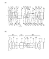
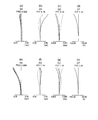
- FIG. 3 is a lens cross-sectional view of the wide-angle optical system of Example 1.
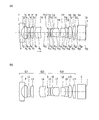
- FIG. 7 is a lens cross-sectional view of the wide-angle optical system of Example 2.
- FIG. 9 is a lens cross-sectional view of the wide-angle optical system of Example 3.
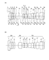
- 9 is a lens cross-sectional view of the wide-angle optical system of Example 4.
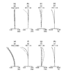
- FIG. 16 is a lens cross-sectional view of the wide-angle optical system of Example 5.
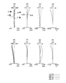
- FIG. 16 is a lens cross-sectional view of the wide-angle optical system of Example 6.
- FIG. 16 is a lens cross-sectional view of the wide-angle optical system of Example 7.
- 16 is a lens cross-sectional view of the wide-angle optical system of Example 8.
- FIG. 16 is a lens cross-sectional view of the wide-angle optical system of Example 9.
- FIG. 20 is a lens cross-sectional view of the wide-angle optical system of Example 10.
- FIG. 16 is a lens cross-sectional view of the wide-angle optical system of Example 11.
- FIG. 16 is a lens cross-sectional view of the wide-angle optical system of Example 12.
- FIG. 16 is a lens cross-sectional view of the wide-angle optical system of Example 13.
- FIG. 16 is a lens cross-sectional view of the wide-angle optical system of Example 14.
- FIG. 7 is an aberration diagram of a wide-angle optical system of Example 1.
- FIG. 9 is an aberration diagram of a wide-angle optical system of Example 2.
- FIG. 9 is an aberration diagram of a wide-angle optical system of Example 3.
- FIG. 7 is an aberration diagram of a wide-angle optical system of Example 1.
- FIG. 9 is an aberration diagram of a wide-angle optical system of Example 2.
- FIG. 9 is an
- FIG. 10 is an aberration diagram of a wide-angle optical system of Example 4.
- FIG. 16 is an aberration diagram of a wide-angle optical system of Example 5.
- FIG. 13 is an aberration diagram of a wide-angle optical system of Example 6.
- FIG. 19 is an aberration diagram of a wide-angle optical system of Example 7.
- FIG. 19 is an aberration diagram of a wide-angle optical system of Example 8.
- FIG. 16 is an aberration diagram of a wide-angle optical system of Example 9.
- FIG. 19 is an aberration diagram of a wide-angle optical system of Example 10.
- FIG. 19 is an aberration diagram of a wide-angle optical system of Example 11.
- 19 is an aberration diagram of a wide-angle optical system of Example 12.
- FIG. 16 is an aberration diagram of a wide-angle optical system of Example 13.
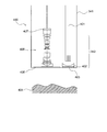
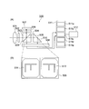
- 19 is an aberration diagram of a wide-angle optical system of Example 14. It is a figure which shows the schematic structure of an endoscope system. It is a figure which shows the structure of the optical system of an endoscope. It is a figure which shows the structure of the optical system of an image pickup apparatus. It is a figure which shows the schematic structure of the image pickup apparatus. It is a figure which shows the positional relationship of an object, an objective optical system, and an optical path dividing element.
- the wide-angle optical system of this embodiment is a wide-angle optical system having a lens component, and the lens component has a plurality of optical surfaces, and in the lens component, two optical surfaces are in contact with air and at least 1
- One optical surface is a curved surface, and in order from the object side, a first lens group having a negative refractive power, a second lens group having a positive refractive power, and a third lens group having a positive refractive power are provided.
- the second lens group moves from the first position toward the second position when the focal position is adjusted from the far point to the near point, and the first position includes the first lens group and the second lens.
- the second position is the position where the distance between the second lens group and the third lens group is the minimum, and the third lens group has three or more lens components.
- the three or more lens components have a first lens component and a second lens component, and the first lens component is the lens component located closest to the object side in the third lens group,
- the second lens component is a lens component located second from the object side in the third lens group, the first lens component is a single lens, the second lens component is a cemented lens, and the following conditional expression ( It is characterized by satisfying 1).
- n2C is the refractive index of the medium located on the object side of the cemented surface of the second lens component with respect to the d-line
- n2C' is the refractive index of the medium located on the image side of the cemented surface of the second lens component with respect to the d-line
- r2C is the radius of curvature of the joint surface, Is.
- the wide-angle optical system of the present embodiment relates to, for example, a wide-angle optical system having an angle of view of more than 100 degrees.
- a wide-angle optical system having an angle of view of more than 100 degrees In recent years, with the advent of high-resolution monitors and the like, high image quality has been required for image quality during observation.
- the wide-angle optical system of this embodiment is a wide-angle optical system that can meet such requirements.
- the wide-angle optical system of this embodiment is an optical system that uses an inner focus. Therefore, the actuator is arranged around the inner focus lens.
- the outer diameter of the entire optical system is small even if the actuator is arranged around the optical system.
- the wide-angle optical system of the present embodiment is an optical system having a wide angle of view, but the light beam height is suppressed to a low value in a long range in the central portion of the optical system.
- the wide-angle optical system of this embodiment is a wide-angle optical system having a lens component.
- the lens component has a plurality of optical surfaces. In the lens component, two optical surfaces are in contact with air and at least one optical surface is a curved surface.
- the lens component includes, for example, a single lens and a junction lens.
- the lens and the parallel flat plate may be joined.
- the optical surface in contact with one air is the lens surface
- the optical surface in contact with the other air is a flat surface.
- a lens component in which a single lens and a parallel flat plate are joined is regarded as a single lens.
- the lens component in which the bonded lens and the parallel flat plate are bonded is regarded as a bonded lens.
- plano-convex lens and the plano-concave lens may be joined.
- the joint surface is a curved surface
- the optical surface in contact with air is a flat surface.
- the surface of the lens component on the object side is the optical surface located on the object side of the two optical surfaces that come into contact with air.
- the image-side surface of the lens component is the optical surface located on the image-side of the two optical surfaces that come into contact with air.
- the cemented surface is located between the object-side surface and the image-side surface.
- the wide-angle optical system of the present embodiment includes a first lens group having a negative refractive power, a second lens group having a positive refractive power, and a third lens group having a positive refractive power in order from the object side. Be prepared.
- the second lens group moves from the first position toward the second position. This movement is a movement in the direction in which the distance between the first lens group and the second lens group increases, and a movement in the direction in which the distance between the second lens group and the third lens group decreases.
- the first position is the position where the distance between the first lens group and the second lens group is minimized.
- the second lens group is located closest to the object in the moving range. In the first position, it is possible to focus on an object located at a distant point.
- the second position is the position where the distance between the second lens group and the third lens group is minimized. At the second position, the second lens group is located closest to the image side in the moving range. At the second position, the object located at the perigee can be focused.
- the third lens group has three or more lens components.
- the three or more lens components include a first lens component and a second lens component.
- the first lens component is the lens component located closest to the object side in the third lens group.
- the second lens component is a lens component located second from the object side in the third lens group.
- the first lens component is a single lens and the second lens component is a cemented lens.
- the optical system has a high resolution, it is possible to obtain a clear image according to the number of pixels even when an image pickup device having a large number of pixels is used.
- the second lens group moves to adjust the focus position.
- An actuator is used to move the second lens group.
- the actuator is arranged near the second lens group or near the third lens group. Therefore, it is necessary to provide a space for arranging the actuator near the second lens group or near the third lens group.
- the ray height can be lowered in a wide range (hereinafter referred to as “predetermined range”) from the object side of the second lens group to the vicinity of the center of the third lens group. be able to.
- conditional expression (1) it is possible to reduce the ray height within a predetermined range. Therefore, the outer diameter of the second lens group and the outer diameter of a part of the third lens group can be reduced. As a result, even if the actuator is arranged, the increase in the outer diameter of the optical unit can be suppressed.
- the field curvature can be corrected at the cemented surface of the second lens component. If it is desired to correct the field curvature satisfactorily, the divergence tends to become stronger at the cemented surface of the second lens component.
- conditional expression (1′) is satisfied instead of conditional expression (1).
- conditional expression (1) -0.50 ⁇ (n2C'-n2C) / r2C ⁇ -0.08 (1')
- conditional expression (1′′) is satisfied instead of conditional expression (1).
- n2C and n2C' represent the refractive index. More specifically, n2C is the refractive index for the d-line of the medium located on the object side of the cemented surface of the second lens component and adjacent to the cemented surface, and n2C' is the image of the cemented surface of the second lens component. It is the refractive index for the d-line of the medium located on the side and adjacent to the joint surface.
- the first lens component have a positive refractive power.
- is preferably 0.25 or more.
- the third lens group has four or more lens components, and has two or more cemented surfaces having a refractive index difference value of 0.25 or more.
- the refractive index difference is the difference between the object side refractive index and the image side refractive index
- the object-side refractive index is a refractive index for a d-line of a medium located on the object side of the cemented surface of the lens component and adjacent to the cemented surface
- the image-side refractive index is the refractive index of the medium located on the image side of the cemented surface of the lens component and adjacent to the cemented surface to the d-line, Is.
- the third lens group include three, four, or five lens components having a positive refractive power.
- the cemented lens located closest to the image side in the third lens group has a positive lens and a negative lens in order from the object side.
- the single lens group is disposed on the most image side of the third lens group, and the single lens group includes two single lenses or three single lenses. It is preferable that the cemented lens is disposed adjacent to the single lens group on the object side of, and the cemented lens has a positive lens and a negative lens in order from the object side.
- one single lens is arranged on the most image side of the third lens group, the cemented lens is arranged adjacent to the single lens on the object side of the single lens, and the cemented lens is It is preferable to have a positive lens and a negative lens in order from the object side.
- the wide-angle optical system of the present embodiment preferably satisfies the following conditional expression (2). 0.05 ⁇ fL / R31F ⁇ 1.2 (2) here, R31F is the radius of curvature of the surface of the first lens component on the object side, fL is the focal length of the wide-angle optical system at the first position, Is.
- Conditional expression (2) is a conditional expression that regulates the convergence of the most object-side surface of the third lens group.
- the first lens component is located closest to the object in the third lens group. Therefore, the conditional expression (2) is a conditional expression that defines the convergence of the object-side surface of the first lens component.
- the object side surface of the first lens component is located closest to the object side in the third lens group.
- conditional expression (2) If the value exceeds the upper limit of conditional expression (2), spherical aberration and coma are likely to occur or the manufacturing error sensitivity is likely to increase. Even if an image sensor having a large number of pixels is used, it becomes difficult to obtain a clear image corresponding to the number of pixels. In addition, it becomes difficult to secure a desired back focus. If the value is less than the lower limit value of the conditional expression (2), the ray height becomes high. Therefore, when the wide-angle optical system of the present embodiment is used for the optical system of the endoscope, the diameter of the insertion portion becomes large.
- conditional expression (2) is satisfied instead of conditional expression (2). 0.10 ⁇ fL / R31F ⁇ 0.90 (2') Further, it is more preferable that the following conditional expression (2′′) is satisfied instead of conditional expression (2). 0.15 ⁇ fL/R31F ⁇ 0.70 (2”)
- An optical system that satisfies the conditional expression (2) has a value smaller than the upper limit value. The smaller the value in the optical system, the easier it is to correct aberrations in the optical system or the easier it is to secure a desired back focus.
- a preferable upper limit value can be set.
- the upper limit is preferably 0.59729, 0.55, or 0.50. By doing so, good aberration correction can be performed.
- 0.20 to 0.45 can be said to be the best range of conditional expression (2).
- 0.40 to 0.65 can be said to be the best range of conditional expression (2).
- P SNi is the refracting power of the joint surface S Ni and is represented by the following equation (4)
- P SNi (n SNi'- n SNi )/r SNi (4)
- n SNi is the refractive index for the d-line of the medium located on the object side of the joint surface S Ni
- n SNi' is the refractive index for the d-line of the medium located on the image side of the junction surface S Ni
- r SNi is the radius of curvature of the joint surface S Ni near the optical axis
- fL is the focal length of the wide-angle optical system at the first position, Is.
- Conditional expression (3) is a conditional expression that defines the refractive power of the cemented surface included in the third lens group. In the predetermined range, it is necessary to keep the light beam diameter small. On the other hand, it is also important to secure a paraxial amount, for example, a focal length or a back focus.
- the lens component located on the object side in the third lens group has strong convergence.
- the third lens group includes N bonding surfaces S Ni .
- the N joint surfaces S Ni are mainly used for correcting curvature of field.
- As the cemented surface S Ni a cemented surface formed by cementing a positive lens having a low refractive power and a negative lens having a high refractive index is used. Therefore, the joint surface S Ni has strong divergence.
- the cemented surface S Ni is preferably arranged on the image side in a predetermined range, for example, at the center of the third lens group.
- conditional expression (3) is satisfied instead of conditional expression (3).
- conditional expression (3) -0.9 ⁇ fL x ⁇ P SNi ⁇ -0.1 (3')
- conditional expression (3 ") instead of the conditional expression (3).
- conditional expression (3) -0.8 ⁇ fL x ⁇ P SNi ⁇ -0.15 (3 ")
- a preferable lower limit value can be set.
- the lower limit value is preferably -0.71747, -0.65, -0.60 or -0.55. By doing so, good aberration correction can be performed.
- conditional expression (3) If priority is given to good aberration correction, -0.50 to -0.20 can be said to be the best range of conditional expression (3). When it is desired to give priority to securing a low light beam height in a predetermined range, it can be said that -0.75 to -0.45 is the best range of the conditional expression (3).
- conditional expression (2) or conditional expression (3) it is possible to easily secure a low ray height in a predetermined range or a desired paraxial amount. It is better if both conditional expression (2) and conditional expression (3) are satisfied.
- conditional expression (2) and conditional expression (3) are satisfied, it becomes difficult to correct astigmatism. Therefore, in the third lens group, it is also necessary to satisfactorily correct astigmatism.
- n SNi and n SNi' represent the refractive index. More specifically, n SNi is located on the object side of the cemented surface S Ni, a and the refractive index at the d-line of the adjacent medium and the joining surface S Ni, n SNi 'is on the image side of the cemented surface S Ni The refractive index for the d-line of the medium located and adjacent to the bonding surface S Ni .
- the third lens group includes the cemented lens closest to the image side among the cemented lenses and the lens component closest to the image side, and is located closest to the image side.
- the cemented lens has a positive refracting power
- the lens component located closest to the image side is a positive single lens, and preferably satisfies the following conditional expression (5).
- R 3R1 is the radius of curvature of the object-side surface of the positive single lens
- R 3R2 is the radius of curvature of the image-side surface of the positive single lens, Is.
- the third lens group has a cemented lens located closest to the image side (hereinafter, referred to as “combined lens A”).
- the cemented lens corresponds to the cemented lens A.
- the cemented lens A When the optical system is divided into two parts, the object side and the image side, with the center of the optical system as the boundary, the cemented lens A is located on the image side. When it is important to secure an appropriate back focus, it is preferable that the cemented lens A has a positive refractive power.
- the lens component closest to the image side be a positive single lens and that conditional expression (5) be satisfied. By doing so, the generation of astigmatism can be suppressed.
- conditional expression (5) If the value exceeds the upper limit of conditional expression (5), or if the value falls below the lower limit of conditional expression (5), it becomes difficult to satisfactorily correct astigmatism.
- conditional expression (5′) is satisfied instead of conditional expression (5).
- conditional expression (5′′) is satisfied instead of conditional expression (5).
- the third lens group includes the cemented lens that is positioned closest to the image side among the cemented lenses and the lens component that is positioned closest to the image side, and is positioned closest to the image side. It is preferable that the cemented lens has a negative refractive power, the lens component located closest to the image side is a positive single lens, and satisfies the following conditional expression (6).
- 'R 3R1 is the radius of curvature of the object-side surface of the positive single lens
- 'R 3R2 is the radius of curvature of the image-side surface of the positive single lens
- shortening the total length of the optical system is more important than securing an appropriate back focus.
- a large positive refractive power is required on the object side of the optical system, and thus a large negative refractive power is required on the image side.
- the cemented lens A is located closest to the image side among the cemented lenses. Therefore, by making the refractive power of the cemented lens A negative, it is possible to obtain a large negative refractive power on the image side. However, in this case, astigmatism is likely to occur or the exit angle of off-axis rays is likely to be large.
- the lens component located closest to the image side be a positive single lens and that conditional expression (6) be satisfied.
- the positive single lens is arranged behind the cemented lens having the negative refractive power. Therefore, the increase in astigmatism can be offset, or the increase in the exit angle of off-axis rays can be offset.
- the off-axis ray height is high in the lens component of the third lens group that is located closest to the image side. Therefore, if a cemented lens is used for this lens component, the thickness of the lens component tends to increase. As a result, it becomes difficult to secure a sufficient back focus or reduce the total length of the optical system.
- conditional expression (6′) may be satisfied. -4.7 ⁇ ( 'R 3R1 +' R 3R2) / ( 'R 3R1 -'R 3R2) ⁇ 0.8 (6') Further, it is more preferable that the following conditional expression (6′′) is satisfied instead of conditional expression (6). -4.5 ⁇ ( 'R 3R1 +' R 3R2) / ( 'R 3R1 -'R 3R2) ⁇ 0.6 (6 ")
- the cemented surface of the third lens group which is located closest to the image side, satisfies the following conditional expression (7).
- r SNr is the radius of curvature of the cemented surface closest to the image side near the optical axis
- fL is the focal length of the wide-angle optical system at the first position, Is.
- Off-axis high-order aberrations are, for example, astigmatism and lateral chromatic aberration.
- conditional expression (7′) is satisfied instead of conditional expression (7).
- conditional expression (7) -0.9 ⁇ fL/r SNr ⁇ 0.0 (7')
- conditional expression (7′′) is satisfied instead of conditional expression (7).
- conditional expression (7) -0.8 ⁇ fL/r SNr ⁇ -0.3 (7”)
- the positive lens is located on the object side of the cemented surface and the negative lens is located on the image side of the cemented surface.
- an appropriate medium may be used as the medium used for the lens.
- spherical aberration, coma, and astigmatism can be satisfactorily corrected, and chromatic aberration can be satisfactorily corrected by selecting an appropriate glass material for the lens.
- the thickness of each lens is larger than the focal length of the optical system.
- the medium of the lens component located on the object side and the medium of the lens component located on the image side can be appropriately set. As a result, it is possible to achieve both the correction of axial chromatic aberration and the correction of lateral chromatic aberration.
- the third lens group has a plurality of positive lenses
- the plurality of positive lenses has a first positive lens and a second positive lens
- the first positive lens is Of the plurality of positive lenses
- the second positive lens is the second positive lens positioned from the object side among the plurality of positive lenses. It is preferable to satisfy the expression (8). -70 ⁇ 31P - ⁇ 32P ⁇ 20 (8) here, ⁇ 31P is the Abbe number of the first positive lens, ⁇ 32P is the Abbe number of the second positive lens, Is.
- Conditional expression (8) defines the relationship between the Abbe number of the first positive lens and the Abbe number of the second positive lens. When the conditional expression (8) is satisfied, it becomes easy to satisfy the design conditions of various optical systems in a state where the correction of the axial chromatic aberration and the correction of the lateral chromatic aberration are made compatible.
- conditional expression (8′) is satisfied instead of conditional expression (8).
- conditional expression (8′′) is satisfied instead of conditional expression (8).
- the third lens group has a plurality of positive lenses, and the plurality of positive lenses include a first positive lens, a second positive lens, and a third positive lens.
- the first positive lens is the positive lens located closest to the object side among the plurality of positive lenses
- the second positive lens is the positive lens located second from the object side among the plurality of positive lenses.
- the third positive lens is a positive lens located third from the object side among the plurality of positive lenses, and preferably satisfies the following conditional expression (9).
- ⁇ 31P is the Abbe number of the first positive lens
- ⁇ 32P is the Abbe number of the second positive lens
- ⁇ 33P is the Abbe number of the third positive lens, Is.
- Conditional expression (9) is a conditional expression that defines the relationship between the average value of the Abbe numbers of the first positive lens and the second positive lens, and the Abbe number of the third positive lens.
- conditional expression (9′) is satisfied instead of conditional expression (9).
- conditional expression (9′′) is satisfied instead of conditional expression (9).
- the third lens group has a plurality of negative lenses
- the plurality of negative lenses has a first negative lens and a second negative lens
- the first negative lens is Of the plurality of negative lenses
- the second negative lens is the second negative lens located from the object side among the plurality of negative lenses. It is preferable to satisfy the formula (10). -30 ⁇ 31N ⁇ 32N ⁇ 40 (10) here, ⁇ 31N is the Abbe number of the first negative lens, ⁇ 32N is the Abbe number of the second negative lens, Is.
- Conditional expression (10) defines the relationship between the Abbe number of the first negative lens and the Abbe number of the second negative lens. When the conditional expression (10) is satisfied, it becomes easy to satisfy the design conditions of various optical systems in a state where the correction of the axial chromatic aberration and the correction of the lateral chromatic aberration are compatible with each other.
- conditional expression (10′) is satisfied instead of conditional expression (10).
- conditional expression (10′′) is satisfied instead of conditional expression (10).
- the third lens group is fixed when adjusting the focal position.
- the manufacturing error sensitivity tends to be high with respect to aberration variation. If the manufacturing error sensitivity is high, the aberration varies greatly even if the manufacturing error is small. Therefore, it is preferable that the third lens group is fixed when adjusting the focal position.
- the wide-angle optical system of the present embodiment preferably satisfies the following conditional expression (11). -50 ⁇ (R21F+R21R)/(R21F-R21R) ⁇ 10 (11) here, R21F is the radius of curvature of the object-side surface of the given lens component, R21R is the radius of curvature of the image-side surface of the given lens component,
- the predetermined lens component is a lens component located closest to the object side in the second lens group, Is.
- the value exceeds the upper limit value of the conditional expression (11)
- the fluctuation of spherical aberration or the fluctuation of astigmatism during focus position adjustment tends to be large.
- the value is less than the lower limit value of the conditional expression (11)
- deterioration of coma aberration and deterioration of astigmatism due to decentering are likely to occur.
- the eccentricity is generated by the movement of the second lens group.
- conditional expression (11) the following conditional expression (11′) may be satisfied.
- conditional expression (11′′) is satisfied instead of conditional expression (11).
- An optical system that satisfies the conditional expression (11) has a value smaller than the upper limit value.
- a preferable upper limit value can be set.
- the upper limit is preferably 5.33106, 1.0, 0.0, or -1.0. Further, it can be said that ⁇ 30.0 to ⁇ 2.0 is the best range of the conditional expression (11).
- the wide-angle optical system of the present embodiment preferably satisfies the following conditional expression (12). 0.2 ⁇ D21/fL ⁇ 3.0 (12) here, D21 is the distance on the optical axis between the most object-side surface and the most image-side surface of the second lens group, fL is the focal length of the wide-angle optical system at the first position, Is.
- One of the controls is to suppress the fluctuation of spherical aberration or the fluctuation of astigmatism when adjusting the focus position.
- the other control is suppression of deterioration of coma due to eccentricity or suppression of deterioration of astigmatism. Eccentricity is caused by the movement of the moving group when adjusting the focal position.
- conditional expression (12) instead of conditional expression (12), the following conditional expression (12′) may be satisfied. 0.2 ⁇ D21/fL ⁇ 2.5 (12') Further, it is better to satisfy the following conditional expression (12 ") instead of the conditional expression (12). 0.4 ⁇ D21/fL ⁇ 2.0 (12”)
- An optical system that satisfies the conditional expression (12) has a value larger than the lower limit value. The larger the value in the optical system, the easier it is for the optical system to achieve both of the above two suppressions.
- a preferable lower limit value can be set.
- the lower limit value is preferably 0.41626, 0.42, 0.43, or 0.44. Further, it can be said that 0.45 to 2.0 is the best range of the conditional expression (12).
- the wide-angle optical system of the present embodiment preferably satisfies the following conditional expression (13). 1.01 ⁇ 2F ⁇ 1.50 (13) here, ⁇ 2F is the magnification of the second lens group at the first position, Is.
- focus sensitivity the focus movement amount with respect to the movement amount of the second lens group becomes too high.
- stop accuracy the accuracy when stopping the second lens group
- the focus sensitivity tends to be low. In this case, since the amount of movement of the second lens group increases, it is necessary to widen the space for movement. Therefore, the optical unit becomes large.
- conditional expression (13′) is satisfied instead of conditional expression (13). 1.00 ⁇ 2F ⁇ 1.40 (13') Further, it is more preferable that the following conditional expression (13′′) is satisfied instead of conditional expression (13). 1.00 ⁇ 2F ⁇ 1.30 (13”)
- the wide-angle optical system of the present embodiment preferably satisfies the following conditional expression (14). 1.01 ⁇ 2N/ ⁇ 2F ⁇ 1.30 (14) here, ⁇ 2F is the magnification of the second lens group at the first position, ⁇ 2N is the magnification of the second lens group at the second position, Is.
- the focal length at the far point becomes short, so a wide angle of view can be secured at the far point. Also, since the focal length at the near point becomes long, a high magnification can be obtained at the near point.
- An optical system that has a wide angle of view at the far point and high magnification at the near point is suitable for the optical system of an endoscope. Therefore, the wide-angle optical system of this embodiment can be used as an optical system of an endoscope.
- the optical system of the endoscope has a wide angle of view in the far point observation and a high magnification in the near point observation.
- the optical system of the endoscope can be focused with high accuracy.
- conditional expression (14) If the value exceeds the upper limit of conditional expression (14), the focus sensitivity on the near point side becomes high. In this case, the stopping accuracy on the near point side is high. Therefore, it becomes difficult to focus with high accuracy.
- the value is less than the lower limit value of the conditional expression (14), it becomes difficult to secure a wide angle of view in the far point observation and a high magnification in the near point observation. Therefore, it is not suitable for the optical system of an endoscope.
- conditional expression (14) instead of the conditional expression (14), the following conditional expression (14') may be satisfied. 1.00 ⁇ 2N/ ⁇ 2F ⁇ 1.20 (14') Further, it is better to satisfy the following conditional expression (14 ") instead of the conditional expression (14). 1.00 ⁇ 2N/ ⁇ 2F ⁇ 1.10 (14”)
- the wide-angle optical system of the present embodiment preferably satisfies the following conditional expression (15). 0.10 ⁇ (1- ⁇ 2F 2 ) ⁇ ⁇ 3F 2 ⁇ 0.55 (15) here, ⁇ 2F is the magnification of the second lens group at the first position, ⁇ 3F is the magnification of the third lens group at the first position, Is.
- the optical unit becomes large.
- conditional expression (15′) may be satisfied. 0.10 ⁇ (1- ⁇ 2F 2 ) ⁇ 3F 2 ⁇ 0.45 (15') Further, it is more preferable that the following conditional expression (15′′) is satisfied instead of conditional expression (15). 0.10 ⁇ (1- ⁇ 2F 2 ) ⁇ 3F 2 ⁇ 0.35 (15”)
- the wide-angle optical system of the present embodiment preferably satisfies the following conditional expression (16). 0.20 ⁇ (1- ⁇ 2N 2 ) ⁇ 3N 2 ⁇ 0.65 (16) here, ⁇ 2N is the magnification of the second lens group at the second position, ⁇ 3N is the magnification of the third lens group at the second position, Is.
- the focus sensitivity on the near point side becomes too high. In this case, the stopping accuracy on the near point side is high. If the value is less than the lower limit value of the conditional expression (16), the focus sensitivity on the near point side tends to be low. In this case, since the amount of movement of the second lens group increases, it is necessary to widen the space for movement.
- conditional expression (16) may be satisfied. 0.20 ⁇ (1- ⁇ 2N 2 ) ⁇ 3N ⁇ 0.50 (16') Further, it is more preferable that the following conditional expression (16′′) is satisfied instead of conditional expression (16). 0.22 ⁇ (1- ⁇ 2N 2 ) ⁇ 3N ⁇ 0.42 (16”)
- the second lens group has only a positive lens.
- the first lens group has only a plurality of negative single lenses, and each of the plurality of negative single lenses is larger than the most object-side positive lens of the third lens group. It preferably has an Abbe number.
- the outer diameter of the first lens group tends to be large.
- the negative refractive power of the first lens group should be increased. If the negative refracting power is increased, off-axis aberrations, particularly astigmatism, are likely to occur.
- the negative refracting power of the first lens group can be shared by the plurality of negative lenses.
- the negative refractive power of the first lens group is increased, it is possible to excellently correct off-axis aberrations, especially astigmatism.
- the first lens group is not intentionally provided with a lens for correcting chromatic aberration.
- the first lens group has only a single lens.
- lateral chromatic aberration is likely to occur in the first lens group.
- lateral chromatic aberration generated in the first lens group can be corrected by the third lens group.
- the Abbe number of the negative single lens of the first lens group is made larger than the Abbe number of the positive lens on the most object side of the third lens group.
- the positive lens closest to the object in the third lens group is located at the closest distance to the negative single lens in the first lens group. Therefore, it becomes possible to correct the lateral chromatic aberration without deteriorating the axial chromatic aberration.
- the Abbe number of the negative single lens in the first lens group is smaller than the Abbe number of the positive lens closest to the object in the third lens group, it becomes difficult to simultaneously correct axial chromatic aberration and lateral chromatic aberration. ..
- the wide-angle optical system of the present embodiment preferably satisfies the following conditional expression (17). 0.2 ⁇ SD1 / fL ⁇ 6.0 (17) here, SD1 is the distance from the most object-side surface of the first lens group to the most image-side surface of the first lens group, fL is the focal length of the wide-angle optical system at the first position, Is.
- the back focus can be secured without increasing the outer diameter of the first lens group, in particular, the outer diameter of the lens closest to the object side, and the angle of view is wide. Also, off-axis aberration, for example, astigmatism can be corrected well.
- conditional expression (17) instead of the conditional expression (17), the following conditional expression (17') may be satisfied. 0.25 ⁇ SD1/fL ⁇ 5.0 (17') Further, it is better to satisfy the following conditional expression (17 ") instead of the conditional expression (17). 0.30 ⁇ SD1/fL ⁇ 4.0 (17”)
- the first lens group has the fourth lens component and the fifth lens component, and the fourth lens component is the lens located closest to the object side in the first lens group.
- the fifth lens component is a lens component located second from the object side in the first lens group, the fourth lens component is a negative lens component, and the fifth lens component is a cemented lens. Therefore, it is preferable that the following conditional expression (18) is satisfied. -1.0 ⁇ fL/R12F a ⁇ 0.5 (18) here, R12F a is the radius of curvature of the surface of the fifth lens component on the object side, fL is the focal length of the wide-angle optical system at the first position, Is.
- the wide-angle optical system of this embodiment has a wide angle of view, it can be used as an endoscope optical system.
- the surface located closest to the object side is a flat surface or a surface convex toward the object side due to the securing of the viewing angle, the restriction of aberration correction, and the restriction of cleaning. Therefore, in the second negative lens from the object side, it is preferable that the object side surface has a strong divergent surface.
- conditional expression (18) If the value exceeds the upper limit of conditional expression (18), the ray height in the first lens group tends to be high. If the value is less than the lower limit of conditional expression (18), astigmatism is likely to occur.
- the fifth lens component is, for example, a negative single lens located second from the object side or a negative junction lens located second from the object side.
- the cemented lens may be formed of a positive lens and a negative lens.
- the positive lens may be located on the object side or the negative lens may be located on the object side.
- conditional expression (18') may be satisfied. -0.7 ⁇ fL / R12F a ⁇ 0.3 (18') Further, it is better to satisfy the following conditional expression (18 ") instead of the conditional expression (18). -0.4 ⁇ fL / R12F a ⁇ 0.2 (18 ")
- the first lens group has a fourth lens component, a fifth lens component, and a sixth lens component
- the fourth lens component is the most in the first lens group. It is a lens component located on the object side
- the fifth lens component is the lens component located second from the object side in the first lens group
- the sixth lens component is the lens component located second from the object side in the first lens group from the object side.
- the third lens component the fourth lens component consists of a negative lens component
- the fifth lens component consists of a lens component having a smaller absolute value of refractive power than the fourth lens component
- the sixth lens component Preferably consists of a cemented lens and satisfies the following conditional expression (19).
- R12F b is the radius of curvature of the object-side surface of the sixth lens component
- fL is the focal length of the wide-angle optical system at the first position, Is.
- the surface closest to the object side is a flat surface or a convex surface on the object side. Therefore, in the third negative lens from the object side, it is preferable that the object side surface has a strong divergent surface.
- conditional expression (19) If the value exceeds the upper limit of conditional expression (19), the ray height in the first lens group tends to be high. If the value is less than the lower limit of conditional expression (19), astigmatism is likely to occur.
- conditional expression (19) the following conditional expression (19′) may be satisfied. -0.7 ⁇ fL/R12F b ⁇ 0.3 (19') Further, it is more preferable that the following conditional expression (19′′) is satisfied instead of conditional expression (19). -0.4 ⁇ fL / R12F b ⁇ 0.2 (19 ")
- the first lens group has the fourth lens component, the fifth lens component, and the sixth lens component, and the fourth lens component is the most in the first lens group.
- the fifth lens component is a lens component located on the object side
- the fifth lens component is a lens component located second from the object side in the first lens group
- the sixth lens component is a lens component located from the object side in the first lens group.
- the fourth lens component is the third lens component
- the fourth lens component is the negative lens component
- the fifth lens component is the negative lens component
- the sixth lens component is the positive lens component. It is preferable to satisfy (20).
- R12F c is the radius of curvature of the object-side surface of the fifth lens component
- fL is the focal length of the wide-angle optical system at the first position, Is.
- the surface closest to the object side is a flat surface or a convex surface on the object side. Therefore, in the second negative lens from the object side, it is preferable that the object side surface has a strong divergent surface.
- conditional expression (20) If the value exceeds the upper limit of conditional expression (20), the ray height in the first lens group tends to be high. If the value is less than the lower limit of conditional expression (20), astigmatism is likely to occur.
- conditional expression (20′) is satisfied instead of conditional expression (20).
- conditional expression (20′′) is satisfied instead of conditional expression (20).
- the first lens group has a negative lens component and a positive lens component and satisfies the following conditional expression (21). -0.4 ⁇ fL / R12R ⁇ 0.02 (21) here, R12R is the radius of curvature of the image side surface of the positive lens component, fL is the focal length of the wide-angle optical system at the first position, Is.
- Using the negative lens component and the positive lens component in the first lens group is slightly disadvantageous in terms of reducing the outer diameter.
- conditional expression (21) If the value exceeds the upper limit of conditional expression (21), the effect of correcting astigmatism is reduced. If the value is less than the lower limit value of the conditional expression (21), the distortion becomes large.
- conditional expression (21′) is satisfied instead of conditional expression (21). -0.3 ⁇ fL/R12R ⁇ 0.0 (21') Further, it is more preferable that the following conditional expression (21′′) is satisfied instead of conditional expression (21). -0.2 ⁇ fL/R12R ⁇ -0.02 (21")
- the first lens group has the fourth lens component and the fifth lens component
- the fourth lens component is the lens located closest to the object side in the first lens group.
- the fifth lens component is a lens component which is the second lens component from the object side in the first lens group and preferably satisfies the following conditional expression (22). -1.0 ⁇ fL/fL12 ⁇ 0.4 (22) here, fL12 is the focal length of the fifth lens component, fL is the focal length of the wide-angle optical system at the first position, Is.
- conditional expression (22′) is satisfied instead of conditional expression (22). -0.7 ⁇ fL/fL12 ⁇ 0.2 (22') Further, it is more preferable that the following conditional expression (22′′) is satisfied instead of conditional expression (22). -0.5 ⁇ fL/fL12 ⁇ 0.05 (22”)
- the wide-angle optical system of the present embodiment preferably satisfies the following conditional expression (23).
- f fin is the focal length of the image-side lens component
- R fin is the radius of curvature of the image-side surface of the image-side lens component
- the image-side lens component is the lens component located closest to the image side among the plurality of lens components, Is.
- an optical element with zero refracting power is often placed between the image-side lens component and the image plane.
- the optical element having zero refractive power is, for example, an optical filter or a prism.
- conditional expressions (5) and (6) the radius of curvature of the surface is defined for the lens component located closest to the image side.
- Conditional expression (23) defines the radius of curvature of the surface of the image-side lens component.
- the image side lens component is a lens component located closest to the image side. Therefore, it can be said that the conditional expression (23) is substantially a conditional expression that limits the conditional expressions (5) and (6).
- the wide-angle optical system of the present embodiment has an image-side lens component and an optical element having a refractive power of zero, and the image-side lens component is located at the most image-side position among a plurality of lens components.
- the element is preferably located on the image side of the image-side lens component, and the image-side lens component and the optical element are preferably cemented together.
- an optical element with zero refracting power is often placed between the image-side lens component and the image plane.
- the optical element having zero refractive power is, for example, an optical filter or a prism.
- the wide-angle optical system of the present embodiment preferably satisfies the following conditional expression (24).
- y max is the maximum image height
- ⁇ max is the angle of view corresponding to the maximum image height
- fL is the focal length of the wide-angle optical system at the first position, Is.
- the wide-angle optical system of this embodiment is an optical system having a high resolution and a small outer diameter by arranging an actuator required for focus position adjustment. Therefore, the wide-angle optical system of this embodiment can be used for an optical system of an endoscope.
- the wide-angle optical system of this embodiment satisfies the conditional expression (24).
- conditional expression (24) it is possible to reduce the outer diameter of the optical unit while ensuring a wide angle of view. Therefore, the wide-angle optical system of this embodiment can be used as an optical system of an endoscope.
- the wide-angle optical system of the present embodiment preferably satisfies the following conditional expression (25).
- ER2 ⁇ 4 ⁇ fL / F EX (25) here, ER2 is the effective radius of the most image-side surface of the second lens component, F EX is the effective F value at the first position, fL is the focal length of the wide-angle optical system at the first position, Is.
- Conditional expression (25) is a conditional expression regarding the ray height. If the conditional expression (25) is satisfied, the wide-angle optical system of this embodiment can be used as an optical system of an endoscope. The effective radius is determined by the height of the outermost ray on the surface.
- the image pickup apparatus of the present embodiment has an optical system and an image pickup element arranged on an image plane, the image pickup element has an image pickup plane, and an image formed on the image pickup plane by the optical system is converted into an electrical signal.
- the optical system is the wide-angle optical system described above.
- the image pickup apparatus of the embodiment even if an image pickup device having a large number of pixels is used, a clear image corresponding to the number of pixels can be obtained.
- (A) is a sectional view at a far point
- (b) is a sectional view at a near point.
- the first lens group is G1, the second lens group is G2, the third lens group is G3, the aperture stop is S, the filter is F, the cover glass is C, C1, C2, the prism is P, and the image surface (imaging surface). Is indicated by I.
- the aberration diagram of each embodiment shows the aberration diagram at the far point and the aberration diagram at the near point in this order.
- (a) shows spherical aberration (SA)
- (b) shows astigmatism (AS)
- (c) shows chromatic aberration of magnification (CC)
- (d) shows distortion (DT).
- SA spherical aberration
- AS astigmatism
- CC chromatic aberration of magnification
- DT distortion
- DT distortion aberration
- the wide-angle optical system of Example 1 includes, in order from the object side, a first lens group G1 having a negative refractive power, a second lens group G2 having a positive refractive power, and a third lens group having a positive refractive power. G3 and.
- the first lens group G1 includes a plano-concave negative lens L1, a biconcave negative lens L2, and a positive meniscus lens L3 having a convex surface directed toward the object side.
- the second lens group G2 has a positive meniscus lens L4 having a convex surface directed toward the object side.
- the third lens group G3 includes a positive meniscus lens L5 having a convex surface directed toward the object side, a negative meniscus lens L6 having a convex surface directed toward the object side, a biconvex positive lens L7, and a positive meniscus lens having a convex surface directed toward the image side. It has an L8, a biconcave negative lens L9, a positive meniscus lens L10 with a convex surface facing the image side, and a biconvex positive lens L11.
- the negative meniscus lens L6 and the biconvex positive lens L7 are joined.
- the positive meniscus lens L8 and the biconcave negative lens L9 are joined.
- the filter F is arranged in the first lens group G1.
- An aperture stop S is arranged between the second lens group G2 and the third lens group G3.
- the cover glass C is arranged on the image side of the third lens group G3.
- the second lens group G2 moves when adjusting the focus position. During the adjustment from the far point to the near point, the second lens group G2 moves to the image side.
- the wide-angle optical system of Example 2 includes, in order from the object side, a first lens group G1 having a negative refractive power, a second lens group G2 having a positive refractive power, and a third lens group having a positive refractive power. G3 and.
- the first lens group G1 includes a negative meniscus lens L1 having a convex surface directed toward the object side, a biconcave negative lens L2, and a positive meniscus lens L3 having a convex surface directed toward the object side.
- the second lens group G2 has a positive meniscus lens L4 having a convex surface directed toward the object side.
- the third lens group G3 includes a positive meniscus lens L5 having a convex surface directed toward the object side, a negative meniscus lens L6 having a convex surface directed toward the object side, a biconvex positive lens L7, and a positive meniscus lens having a convex surface directed toward the image side.
- L8 a biconcave negative lens L9, a biconvex positive lens L10, and a biconvex positive lens L11.
- the negative meniscus lens L6 and the biconvex positive lens L7 are joined.
- the positive meniscus lens L8 and the biconcave negative lens L9 are joined.
- the filter F is arranged in the first lens group G1.
- An aperture stop S is arranged between the second lens group G2 and the third lens group G3.
- the cover glass C is arranged on the image side of the third lens group G3.
- the second lens group G2 moves when adjusting the focus position. During the adjustment from the far point to the near point, the second lens group G2 moves to the image side.
- the wide-angle optical system of Example 3 includes, in order from the object side, a first lens group G1 having a negative refractive power, a second lens group G2 having a positive refractive power, and a third lens group having a positive refractive power. G3 and.
- the first lens group G1 includes a negative meniscus lens L1 having a convex surface directed toward the object side, a biconcave negative lens L2, and a positive meniscus lens L3 having a convex surface directed toward the object side.
- the second lens group G2 has a positive meniscus lens L4 having a convex surface directed toward the object side.
- the third lens group G3 includes a positive meniscus lens L5 having a convex surface directed toward the object side, a positive meniscus lens L6 having a convex surface directed toward the object side, a biconvex positive lens L7, and a positive meniscus lens having a convex surface directed toward the image side. It has an L8, a biconcave negative lens L9, a positive meniscus lens L10 with a convex surface facing the image side, and a biconvex positive lens L11.
- the positive meniscus lens L6 and the biconvex positive lens L7 are cemented together.
- the positive meniscus lens L8 and the biconcave negative lens L9 are joined.
- the filter F is arranged in the first lens group G1.
- An aperture stop S is arranged between the second lens group G2 and the third lens group G3.
- the cover glass C is arranged on the image side of the third lens group G3.
- the second lens group G2 moves when adjusting the focus position. During the adjustment from the far point to the near point, the second lens group G2 moves to the image side.
- the wide-angle optical system of Example 4 includes, in order from the object side, a first lens group G1 having a negative refractive power, a second lens group G2 having a positive refractive power, and a third lens group having a positive refractive power. It has G3 and.
- the first lens group G1 includes a negative meniscus lens L1 having a convex surface directed toward the object side, a biconcave negative lens L2, and a positive meniscus lens L3 having a convex surface directed toward the object side.
- the second lens group G2 has a positive meniscus lens L4 having a convex surface directed toward the object side.
- the third lens group G3 includes a positive meniscus lens L5 having a convex surface directed toward the object side, a biconcave negative lens L6, a biconvex positive lens L7, a positive meniscus lens L8 having a convex surface directed toward the image side, and a biconcave negative lens. It has a lens L9, a biconvex positive lens L10, and a positive meniscus lens L11 having a convex surface facing the object side.
- the biconcave negative lens L6 and the biconvex positive lens L7 are cemented together.
- the positive meniscus lens L8 and the biconcave negative lens L9 are joined.
- the filter F is arranged in the first lens group G1.
- An aperture stop S is arranged between the second lens group G2 and the third lens group G3.
- the cover glass C is arranged on the image side of the third lens group G3.
- the second lens group G2 moves when adjusting the focus position. During the adjustment from the far point to the near point, the second lens group G2 moves to the image side.
- the wide-angle optical system of Example 5 includes, in order from the object side, a first lens group G1 having a negative refractive power, a second lens group G2 having a positive refractive power, and a third lens group having a positive refractive power. G3 and.
- the first lens group G1 includes a negative meniscus lens L1 having a convex surface directed toward the object side, a biconcave negative lens L2, and a positive meniscus lens L3 having a convex surface directed toward the object side.
- the second lens group G2 has a positive meniscus lens L4 having a convex surface directed toward the object side.
- the third lens group G3 includes a positive meniscus lens L5 having a convex surface directed toward the object side, a negative meniscus lens L6 having a convex surface directed toward the object side, a biconvex positive lens L7, a biconvex positive lens L8, and a biconcave negative lens. It has a lens L9, a biconvex positive lens L10, and a positive meniscus lens L11 with a convex surface facing the object side.
- the negative meniscus lens L6 and the biconvex positive lens L7 are joined.
- the biconvex positive lens L8 and the biconcave negative lens L9 are joined.
- the filter F is arranged in the first lens group G1.
- An aperture stop S is arranged between the second lens group G2 and the third lens group G3.
- the cover glass C is arranged on the image side of the third lens group G3.
- the second lens group G2 moves when adjusting the focus position. During the adjustment from the far point to the near point, the second lens group G2 moves to the image side.
- the wide-angle optical system of Example 6 includes, in order from the object side, a first lens group G1 having a negative refractive power, a second lens group G2 having a positive refractive power, and a third lens group having a positive refractive power. G3 and.
- the first lens group G1 includes a plano-concave negative lens L1, a biconcave negative lens L2, and a positive meniscus lens L3 with a convex surface facing the image side.
- the second lens group G2 has a positive meniscus lens L4 having a convex surface directed toward the object side.
- the third lens group G3 includes a positive meniscus lens L5 with a convex surface facing the object side, a biconvex positive lens L6, a negative meniscus lens L7 with a convex surface facing the image side, a biconvex positive lens L8, and both concave and negative. It has a lens L9, a biconvex positive lens L10, a biconvex positive lens L11, and a plano-convex positive lens L12.
- the biconvex positive lens L6 and the negative meniscus lens L7 are joined.
- the biconvex positive lens L8 and the biconcave negative lens L9 are joined.
- the filter F is arranged in the first lens group G1.
- the aperture stop S is arranged in the third lens group G3.
- the cover glass C is arranged on the image side of the third lens group G3.
- the plano-convex positive lens L12 and the cover glass C are cemented together.
- the second lens group G2 moves when adjusting the focus position. During the adjustment from the far point to the near point, the second lens group G2 moves to the image side.
- the wide-angle optical system of Example 7 includes, in order from the object side, a first lens group G1 having a negative refractive power, a second lens group G2 having a positive refractive power, and a third lens group having a positive refractive power. G3 and.
- the first lens group G1 includes a plano-concave negative lens L1, a biconcave negative lens L2, and a negative meniscus lens L3 having a convex surface directed toward the image side.
- the second lens group G2 has a positive meniscus lens L4 having a convex surface directed toward the object side.
- the third lens group G3 includes a positive meniscus lens L5 with a convex surface facing the object side, a biconvex positive lens L6, a negative meniscus lens L7 with a convex surface facing the image side, a biconvex positive lens L8, and both concave and negative. It has a lens L9, a biconvex positive lens L10, a biconvex positive lens L11, and a plano-convex positive lens L12.
- the biconvex positive lens L6 and the negative meniscus lens L7 are joined.
- the biconvex positive lens L8 and the biconcave negative lens L9 are joined.
- the filter F is arranged in the first lens group G1.
- the aperture stop S is arranged in the third lens group G3.
- the cover glass C is arranged on the image side of the third lens group G3.
- the plano-convex positive lens L12 and the cover glass C are cemented together.
- the second lens group G2 moves when adjusting the focus position. During the adjustment from the far point to the near point, the second lens group G2 moves to the image side.
- the wide-angle optical system of Example 8 includes, in order from the object side, a first lens group G1 having a negative refractive power, a second lens group G2 having a positive refractive power, and a third lens group having a positive refractive power. G3 and.
- the first lens group G1 includes a plano-concave negative lens L1, a biconcave negative lens L2, and a biconvex positive lens L3.
- the biconcave negative lens L2 and the biconvex positive lens L3 are cemented together.
- the second lens group G2 has a positive meniscus lens L4 having a convex surface directed toward the object side.
- the third lens group G3 includes a biconvex positive lens L5, a biconcave negative lens L6, a biconvex positive lens L7, a positive meniscus lens L8 having a convex surface facing the image side, and a negative meniscus having a convex surface facing the image side. It has a lens L9 and a biconvex positive lens L10.
- the biconcave negative lens L6 and the biconvex positive lens L7 are cemented together.
- the positive meniscus lens L8 and the negative meniscus lens L9 are cemented.
- the filter F is arranged in the first lens group G1.
- the aperture stop S is arranged in the third lens group G3.
- a cover glass C1, a prism P, and a cover glass C2 are arranged on the image side of the third lens group G3.
- the second lens group G2 moves when adjusting the focus position. During the adjustment from the far point to the near point, the second lens group G2 moves to the image side.
- the wide-angle optical system of Example 9 includes, in order from the object side, a first lens group G1 having a negative refractive power, a second lens group G2 having a positive refractive power, and a third lens group having a positive refractive power. G3 and.
- the first lens group G1 has a plano-concave negative lens L1.
- the second lens group G2 has a positive meniscus lens L2 having a convex surface directed toward the image side.
- the third lens group G3 includes a biconvex positive lens L3, a biconcave negative lens L4, a biconvex positive lens L5, a positive meniscus lens L6 having a convex surface facing the image side, and a negative meniscus having a convex surface facing the image side. It has a lens L7 and a biconvex positive lens L8.
- the biconcave negative lens L4 and the biconvex positive lens L5 are cemented together.
- the positive meniscus lens L6 and the negative meniscus lens L7 are cemented.
- a filter F is arranged between the first lens group G1 and the second lens group G2.
- the aperture stop S is arranged in the third lens group G3.
- a cover glass C1, a prism P, and a cover glass C2 are arranged on the image side of the third lens group G3.
- the second lens group G2 moves when adjusting the focus position. During the adjustment from the far point to the near point, the second lens group G2 moves to the image side.
- the wide-angle optical system of Example 10 includes, in order from the object side, a first lens group G1 having a negative refractive power, a second lens group G2 having a positive refractive power, and a third lens group having a positive refractive power. G3 and.
- the first lens group G1 has a plano-concave negative lens L1 and a negative meniscus lens L2 with a convex surface facing the object side.
- the second lens group G2 has a positive meniscus lens L3 having a convex surface directed toward the object side.
- the third lens group G3 includes a biconvex positive lens L4, a biconcave negative lens L5, a biconvex positive lens L6, a positive meniscus lens L7 having a convex surface facing the image side, and a negative meniscus having a convex surface facing the image side. It has a lens L8 and a biconvex positive lens L9.
- the biconcave negative lens L5 and the biconvex positive lens L6 are cemented together.
- the positive meniscus lens L7 and the negative meniscus lens L8 are cemented together.
- a filter F is arranged between the first lens group G1 and the second lens group G2.
- the aperture stop S is arranged in the third lens group G3.
- a cover glass C1, a prism P, and a cover glass C2 are arranged on the image side of the third lens group G3.
- the second lens group G2 moves when adjusting the focus position. During the adjustment from the far point to the near point, the second lens group G2 moves to the image side. The filter F moves together with the second lens group G2.
- the wide-angle optical system of Example 11 includes, in order from the object side, a first lens group G1 having a negative refractive power, a second lens group G2 having a positive refractive power, and a third lens group having a positive refractive power. G3 and.
- the first lens group G1 includes a plano-concave negative lens L1, a biconcave negative lens L2, and a positive meniscus lens L3 having a convex surface directed toward the object side. Both concave negative lenses L2 and positive meniscus lens L3 are joined.
- the second lens group G2 has a positive meniscus lens L4 having a convex surface directed toward the object side.
- the third lens group G3 includes a positive meniscus lens L5 having a convex surface directed toward the object side, a negative meniscus lens L6 having a convex surface directed toward the object side, a biconvex positive lens L7, and a negative meniscus lens having a convex surface directed toward the object side. It has L8, a biconvex positive lens L9, and a plano-convex positive lens L10.
- the negative meniscus lens L6 and the biconvex positive lens L7 are joined.
- the negative meniscus lens L8 and the biconvex positive lens L9 are cemented together.
- the filter F is arranged in the first lens group G1.
- the aperture stop S is arranged in the third lens group G3.
- the cover glass C is arranged on the image side of the third lens group G3.
- the plano-convex positive lens L10 and the cover glass C are cemented together.
- the second lens group G2 moves when adjusting the focus position. During the adjustment from the far point to the near point, the second lens group G2 moves to the image side.
- the wide-angle optical system of Example 12 includes, in order from the object side, a first lens group G1 having a negative refractive power, a second lens group G2 having a positive refractive power, and a third lens group having a positive refractive power. G3 and.
- the first lens group G1 includes a plano-concave negative lens L1, a biconcave negative lens L2, and a biconvex positive lens L3.
- the biconcave negative lens L2 and the biconvex positive lens L3 are cemented together.
- the second lens group G2 has a positive meniscus lens L4 having a convex surface directed toward the object side.
- the third lens group G3 includes a biconvex positive lens L5, a biconvex positive lens L6, a negative meniscus lens L7 having a convex surface directed toward the image side, and a plano-convex positive lens L8.
- the biconvex positive lens L6 and the negative meniscus lens L7 are cemented together.
- An aperture stop S is arranged between the second lens group G2 and the third lens group G3.
- the filter F is arranged in the third lens group G3.
- the cover glass C is arranged on the image side of the third lens group G3.
- the plano-convex positive lens L8 and the cover glass C are cemented together.
- the second lens group G2 moves when adjusting the focus position. During the adjustment from the far point to the near point, the second lens group G2 moves to the image side.
- the wide-angle optical system of Example 13 includes, in order from the object side, a first lens group G1 having a negative refractive power, a second lens group G2 having a positive refractive power, and a third lens group having a positive refractive power. G3 and.
- the first lens group G1 has a plano-concave negative lens L1 and a positive meniscus lens L2 with a convex surface facing the image side.
- the second lens group G2 has a biconvex positive lens L3.
- the third lens group G3 includes a positive meniscus lens L4 having a convex surface directed toward the object side, a negative meniscus lens L5 having a convex surface directed toward the object side, a biconvex positive lens L6, a biconvex positive lens L7, and an image side. It has a negative meniscus lens L8 having a convex surface and a plano-convex positive lens L9.
- the negative meniscus lens L5 and the biconvex positive lens L6 are joined.
- the biconvex positive lens L7 and the negative meniscus lens L8 are cemented
- An aperture stop S and a filter F are arranged in the third lens group G3.
- the cover glass C is arranged on the image side of the third lens group G3.
- the plano-convex positive lens L9 and the cover glass C are cemented together.
- the second lens group G2 moves when adjusting the focus position. During the adjustment from the far point to the near point, the second lens group G2 moves to the image side.
- the wide-angle optical system of Example 14 includes, in order from the object side, a first lens group G1 having a negative refractive power, a second lens group G2 having a positive refractive power, and a third lens group having a positive refractive power. G3 and.
- the first lens group G1 includes a plano-concave negative lens L1, a biconcave negative lens L2, and a biconvex positive lens L3.
- the biconcave negative lens L2 and the biconvex positive lens L3 are cemented together.
- the second lens group G2 has a positive meniscus lens L4 having a convex surface directed toward the object side.
- the third lens group G3 includes a plano-convex positive lens L5, a negative meniscus lens L6 having a convex surface directed toward the object side, a plano-convex positive lens L7, a biconvex positive lens L8, and a negative meniscus surface convex on the image side. It has a lens L9 and a plano-convex regular lens L10.
- the negative meniscus lens L6 and the plano-convex positive lens L7 are cemented together.
- the biconvex positive lens L8 and the negative meniscus lens L9 are cemented together.
- An aperture stop S and a filter F are arranged in the third lens group G3.
- the cover glass C is arranged on the image side of the third lens group G3.
- the plano-convex positive lens L10 and the cover glass C are cemented together.
- the second lens group G2 moves when adjusting the focus position. During the adjustment from the far point to the near point, the second lens group G2 moves to the image side.
- the numerical data of each of the above examples are shown below.
- r is the radius of curvature of each lens surface
- d is the distance between the lens surfaces
- nd is the d-line refractive index of each lens
- ⁇ d is the Abbe number of each lens
- * mark is an aspherical surface.
- the diaphragm is a brightness diaphragm.
- OBJ is the object distance
- FL is the focal length of the entire system
- MG is the magnification of the entire system
- FNO is the F number
- FIY and FIM are the image heights
- LTL is the total length of the optical system
- FB is the back focus. is there.
- the back focus is the distance from the most image-side lens surface to the paraxial image surface, which is expressed in air.
- the total length is the distance from the lens surface on the most object side to the lens surface on the image side with back focus added.
- ⁇ 1 is the magnification of the first lens group
- ⁇ 2 is the magnification of the second lens group
- ⁇ 3 is the magnification of the third lens group.
- f1, f2 are focal lengths of each lens group.
- the aspherical shape has the following equation when the optical axis direction is z, the direction orthogonal to the optical axis is y, the conical coefficient is k, and the aspherical coefficient is A4, A6, A8, A10, A12, and so on. expressed.
- z (y 2 /r)/[1+ ⁇ 1-(1+k)(y/r) 2 ⁇ 1/2 ] +A4y 4 +A6y 6 +A8y 8 +A10y 10 +A12y 12 +...
- E ⁇ n (n is an integer) indicates 10 to the n-th power.
- Numerical Example 1 Unit mm Surface data Surface number r d nd ⁇ d ER Object ⁇ 21.0000 1. 1 ⁇ 0.3700 1.88300 40.76 1.881 2 1.8089 0.6000 1. 1.306 3 ⁇ 0.4000 1.51633 64.14 1.293 4 ⁇ 0.1633 1. 1.209 5 -7.7140 0.2984 1.88300 40.76 1.185 6 3.9041 0.0965 1. 1.135 7 2.4546 0.8446 1.92286 18.90 1.157 8 3.1566 d8 1. 1.013 9 2.2403 1.5268 1.49700 81.54 0.981 10 3.3915 d10 1.0.697 11 (Aperture) ⁇ 0.0783 1.
- Numerical Example 2 Unit mm Surface data Surface number r d nd ⁇ d ER Object ⁇ 17.0000 1. 1 20.0000 0.3700 1.88300 40.76 1.562 2 1.2067 0.6000 1. 0.977 3 ⁇ 0.4000 1.51633 64.14 0.943 4 ⁇ 0.1010 1. 0.858 5 -5.0015 0.2886 1.88300 40.76 0.848 6 2.9519 0.0923 1. 0.809 7 1.8550 0.3815 1.92286 18.90 0.826 8 2.6141 d8 1.
- Numerical Example 3 Unit mm Surface data Surface number r d nd ⁇ d ER Object ⁇ 17.0000 1. 1 20.0000 0.3700 1.88300 40.76 1.565 2 1.1942 0.6000 1. 0.975 3 ⁇ 0.3600 1.51633 64.14 0.945 4 ⁇ 0.0180 1. 0.872 5 -39.2627 0.2712 1.88300 40.76 0.869 6 2.1856 0.0689 1. 0.804 7 1.5 180 0.3499 1.92286 18.90 0.813 8 1.8920 d8 1. 0.744 9 1.3113 0.3642 1.49700 81.54 0.700 10 1.5503 d10 1.0.619 11 (Aperture) ⁇ 0.0540 1.
- Numerical Example 4 Unit mm Surface data Surface number r d nd ⁇ d ER Object ⁇ 17.0000 1. 1 20.0000 0.3700 1.88300 40.76 2.170 2 1.8355 0.6000 1. 1.438 3 ⁇ 0.4000 1.51633 64.14 1.482 4 ⁇ 0.3651 1. 1.367 5 -6.0073 0.7484 1.88300 40.76 1.260 6 3.8110 0.5388 1. 1.141 7 2.9102 0.4410 1.92286 18.90 1.179 8 4.0476 d8 1. 1.118 9 2.4287 1.7001 1.49700 81.54 1.088 10 3.4681 d10 1.0.763 11 (Aperture) ⁇ 0.0944 1.
- Numerical Example 6 Unit mm Surface data Surface number r d nd ⁇ d ER Object ⁇ 23.0000 1. 1 ⁇ 0.3000 1.88300 40.76 1.571 2 1.7470 0.6621 1. 1.132 3* -4.2685 0.3000 1.72916 54.68 1.063 4* 3.7770 0.2160 1.
- Numerical Example 7 Unit mm Surface data Surface number r d nd ⁇ d ER Object ⁇ 23.0000 1. 1 ⁇ 0.3000 1.88300 40.76 1.583 2 1.7269 0.6987 1. 1.137 3 -4.9307 0.3000 1.72916 54.68 1.072 4 4.3840 0.2021 1. 1.007 5 ⁇ 0.4000 1.51633 64.14 1.003 6 ⁇ 0.0980 1. 0.992 7 -26.4786 0.4796 1.92286 18.90 0.989 8 -45.6102 d8 1.
- Numerical Example 8 Unit mm Surface data Surface number r d nd ⁇ d ER Object ⁇ 16.0000 1. 1 ⁇ 0.2500 1.88300 40.76 1.282 2* 0.9612 0.6709 1. 0.877 3 ⁇ 0.4000 1.49400 75.01 0.833 4 ⁇ 0.1500 1. 0.782 5 -5.5346 0.2500 1.77250 49.60 0.764 6 2.4020 0.4500 1.95906 17.47 0.745 7 -15.4746 d7 1.0.724 8* 8.6565 0.5000 1.74320 49.34 0.659 9* 51.2636 d9 1.0.628 10 2.9556 0.4161 1.65160 58.55 0.560 11 -8.3048 0.1000 1.
- Numerical Example 9 Unit mm Surface data Surface number r d nd ⁇ d ER Object ⁇ 16.0000 1. 1 ⁇ 0.2500 1.88300 40.76 1.264 2* 0.9272 1.1000 1. 0.857 3 ⁇ 0.4000 1.49400 75.01 0.751 4 ⁇ d4 1. 0.708 5* -9.5539 0.6179 1.88300 40.76 0.626 6* -6.5358 d6 1.0.620 7 4.3878 0.4161 1.95906 17.47 0.560 8 -3.3352 0.1000 1.0.439 9 (Aperture) ⁇ 0.1000 1.
- Numerical Example 10 Unit mm Surface data Surface number r d nd ⁇ d ER Paraboloid ⁇ 15.8000 1. 1 ⁇ 0.2500 1.88300 40.76 1.298 2 * 1.1014 0.7055 1. 0.910 3 4.9262 0.2500 1.88300 40.76 0.812 4 2.2000 d4 1. 0.743 5 ⁇ 0.4000 1.49400 75.01 0.690 6 ⁇ 0.1000 1. 0.674 7* 1.8277 0.5170 1.51633 64.14 0.660 8 * 2.3331 d8 1. 0.590 9 4.0162 0.4161 1.95906 17.47 0.560 10 -3.2257 0.1000 1. 0.448 11 (Aperture) ⁇ 0.1000 1.
- Numerical Example 11 Unit mm Surface data Surface number r d nd ⁇ d ER Object ⁇ 12.5000 1. 1 ⁇ 0.2500 1.88300 40.76 1.337 2* 0.8692 0.5880 1. 0.900 3 ⁇ 0.4000 1.49400 75.01 0.887 4 ⁇ 0.0878 1. 0.848 5 -9.0618 0.2500 1.81600 46.62 0.841 6 1.0427 0.7558 1.80518 25.42 0.815 7 17.0221 d7 1. 0.801 8* 3.0758 0.4338 1.80610 40.92 0.798 9 3.6580 d9 1. 0.740 10* 2.1247 0.6051 1.72916 54.68 0.650 11* 9.8770 0.1000 1.
- Numerical Example 12 Unit mm Surface data Surface number r d nd ⁇ d ER Object ⁇ 12.0000 1. 1 ⁇ 0.2500 1.88300 40.76 0.959 2* 0.5867 0.7292 1. 0.604 3 -2.9628 0.2500 1.77250 49.60 0.580 4 1.8141 0.6400 1.84666 23.78 0.598 5 -3.6936 d5 1.0.611 6 1.4089 0.5984 1.65160 58.55 0.568 7 1.5806 d7 1.0.446 8 (Aperture) ⁇ 0.1000 1.
- Numerical Example 13 Unit mm Surface data Surface number r d nd ⁇ d ER Object ⁇ 12.0000 1. 1 ⁇ 0.2500 1.88300 40.76 0.893 2 * 0.6145 0.5000 1. 0.568 3 -4.0000 0.3000 1.84666 23.78 0.553 4-3.4224 d4 1. 0.560 5* 31.9001 0.5000 1.88300 40.76 0.515 6 * -17.3823 d6 1. 0.495 7 1.8552 0.3300 1.84666 23.78 0.350 8 46.7757 0.1000 1. 0.326 9 (Aperture) ⁇ 0.1000 1.
- Numerical Example 14 Unit mm Surface data Surface number r d nd ⁇ d ER Object ⁇ 12.0000 1. 1 ⁇ 0.3000 1.88300 40.76 0.956 2 * 0.6059 0.5726 1. 0.590 3 -2.2791 0.3000 1.77250 49.60 0.568 4 2.2000 0.6000 1.84666 23.78 0.588 5 -5.1712 d5 1. 0.611 6 * 1.1177 0.5146 1.51633 64.14 0.582 7 * 1.2614 d7 1. 0.492 8 2.4878 0.3800 1.72916 54.68 0.408 9 ⁇ 0.1000 1. 0.378 10 (Aperture) ⁇ 0.1000 1.
- Example 1 Example 2
- Example 3 (1)(n2C'-n2C) /r2C -0.242749 -0.4375015 -0.1993855 (2) fL / R31F 0.23622396 0.4082845 0.3589840 (3) fL ⁇ P SNi -0.4654942 -0.6185885 -0.3890205 (5) (R 3R1 +R 3R2 ) / (R 3R1 -R 3R2 ) ---- (6) ('R 3R1 +'R 3R2 ) / ( 'R 3R1 -'R 3R2) -0.918874 -0.9152799 -0.7843584 (7)fL/r SNr -0.7041468 -0.6722869 -0.6495990 (8) ⁇ 31P - ⁇ 32P -11.67 -23.38 -23.
- FIG. 29 is an example of an imaging device.
- the imaging device is an endoscope system.
- FIG. 29 is a diagram showing a schematic configuration of the endoscope system.
- the endoscope system 300 is an observation system using an electronic endoscope.
- the endoscope system 300 includes an electronic endoscope 310 and an image processing device 320.
- the electronic endoscope 310 includes a scope unit 310a and a connection cord unit 310b.
- a display unit 330 is connected to the image processing device 320.
- the scope unit 310a is roughly divided into an operation unit 340 and an insertion unit 341.
- the insertion portion 341 is elongated and can be inserted into the body cavity of the patient. Further, the insertion portion 341 is made of a flexible member. The observer can perform various operations using an angle knob or the like provided on the operation unit 340.
- connection cord unit 310b extends from the operation unit 340.
- the connection cord portion 310b includes a universal cord 350.
- the universal cord 350 is connected to the image processing device 320 via the connector 360.
- the universal code 350 is used to send and receive various signals.
- Various signals include a power supply voltage signal and a CCD drive signal. These signals are transmitted from the power supply device or the video processor to the scope unit 310a. Further, there are video signals as various signals. This signal is transmitted from the scope unit 310a to the video processor.
- Peripheral devices such as a VTR deck and a video printer (not shown) can be connected to the video processor in the image processing device 320.
- the video processor performs signal processing on the video signal from the scope unit 310a.
- An endoscopic image is displayed on the display screen of the display unit 330 based on the video signal.
- FIG. 30 is a diagram showing the configuration of the optical system of the endoscope.
- the optical system 400 has an illumination unit and an observation unit.
- the illumination unit has a light guide 401 and an illumination lens 402.
- the light guide 401 transmits the illumination light to the tip portion 342 of the insertion portion 341.
- the transmitted illumination light is emitted from the tip surface of the light guide 401.
- the illumination lens 402 is arranged at the tip portion 342.
- the illumination lens 402 is arranged at a position facing the tip surface of the light guide 401.
- the illumination light passes through the illumination lens 402 and exits from the illumination window 403.
- observation region 404 the observation target region inside the subject
- An observation window 405 is provided on the tip portion 342 next to the illumination window 403.
- the light from the observation site 404 passes through the observation window 405 and enters the tip portion 342.
- An observation unit is provided behind the observation window 405.
- the observation unit has a wide-angle optical system 406 and an image sensor 407.
- the wide-angle optical system 406 for example, the wide-angle optical system of Example 1 is used.
- the reflected light from the observation region 404 passes through the wide-angle optical system 406 and enters the image sensor 407.
- An image (optical image) of the observation site 404 is formed on the imaging surface of the imaging element 407.
- the image of the observation region 404 is photoelectrically converted by the image sensor 407, and the image of the observation region 404 is obtained.
- the image of the observed region 404 is displayed on the display unit 330. In this way, the observer can observe the image of the observation region 404.
- the image plane has a curved shape.
- the image sensor 407 has a curved light-receiving surface (imaging surface) that is the same as the shape of the image surface. By using the image pickup element 407, the image quality of a captured image can be improved.
- FIG. 31 is a diagram showing the configuration of the optical system of the imaging device.
- the optical system has an objective optical system OBJ, a cover glass C, and a prism P.
- the cover glass C is arranged between the objective optical system OBJ and the prism P.
- An optical filter may be arranged instead of the cover glass C. Alternatively, the cover glass C may not be arranged.
- the wide-angle optical system of Example 8 is used for the objective optical system OBJ. Further, in FIG. 31, the cover glass C'is arranged between the prism P and the image plane I.
- the prism P has a prism P1 and a prism P2.
- the prisms P1 and P2 are both triangular prisms.
- An optical path splitting element is formed by the prism P1 and the prism P2.
- the prism P1 has an optical surface S1, an optical surface S2, and an optical surface S3.
- the prism P2 has an optical surface S3, an optical surface S4, and an optical surface S5.
- the prism P1 is joined to the prism P2.
- a joint surface is formed by the prism P1 and the prism P2.
- the optical surface S3 is a cemented surface.
- imaging light The light emitted from the objective optical system OBJ (hereinafter referred to as "imaging light") passes through the cover glass C and is incident on the optical surface S1. Since the optical surface S1 is a transmitting surface, the imaging light is transmitted through the optical surface S1.
- the imaging light is incident on the optical surface S3.
- the optical surface S3 is arranged so that the normal to the surface is 45 degrees with respect to the optical axis.
- the imaging light incident on the optical surface S3 is the light transmitted through the optical surface S3 (hereinafter referred to as "imaging light 1") and the light reflected by the optical surface S3 (hereinafter referred to as "imaging light 2").
- imaging light 1 the light transmitted through the optical surface S3
- imaging light 2 the light reflected by the optical surface S3
- the image-forming light 1 and the image-forming light 2 travel in mutually different directions.
- the optical surface S3 forms the first optical path and the second optical path. In this way, the optical surface S3 functions as an optical path dividing surface.
- the first optical path is formed on the extension of the optical path of the objective optical system OBJ.
- the second optical path is formed so as to intersect with the first optical path. In FIG. 31, the second optical path is orthogonal to the first optical path.
- the optical surface S3, the optical surface S4, and the optical surface S5 are located in the first optical path.
- the imaging light 1 that has passed through the optical surface S3 enters the optical surface S4.
- the optical surface S4 is a reflecting surface.
- the imaging light 1 is reflected by the optical surface S4 and enters the optical surface S5.
- the optical surface S5 is a transmission surface.
- the imaging light 1 passes through the optical surface S5 and is focused on the image plane I near the optical surface S5. An optical image is formed on the image plane I by the imaging light 1.
- the optical surface S3, the optical surface S2, the optical surface S3, and the optical surface S5 are located in the second optical path.
- the imaging light 2 reflected by the optical surface S3 is incident on the optical surface S2.
- the optical surface S2 is a reflecting surface.
- the imaging light 2 is reflected by the optical surface S2 and is incident on the optical surface S3.
- On the optical surface S3, the imaging light 2 is divided into light that passes through the optical surface S3 and light that is reflected by the optical surface S3.
- the imaging light 2 transmitted through the optical surface S3 is incident on the optical surface S5.
- the imaging light 2 passes through the optical surface S5 and is focused on the image plane I near the optical surface S5.
- An optical image formed by the imaging light 2 is formed on the image plane I.
- optical path length in the first optical path and the optical path length in the second optical path are equal, two in-focus optical images are formed at different positions in the same plane.
- the two optical images are optical images when the same object is in focus. Therefore, the position of the object plane in one optical image is the same as the position of the object plane in the other optical image.
- the optical path length in the first optical path and the optical path length in the second optical path are different, two in-focus optical images are formed at different positions in the same plane.
- the two optical images are optical images when different objects are in focus. Therefore, the position of the object plane in one optical image is different from the position of the object plane in the other optical image.
- the optical path length in the first optical path is shorter than the optical path length in the second optical path.
- the object surface of the optical image formed by the imaging light 1 is located farther than the object surface formed by the imaging light 2.
- object distance two object surfaces having different distances from the objective optical system OBJ (hereinafter referred to as "object distance") are focused on each other. Even if the two object planes have different object distances, two optical images are formed at different positions in the same plane.
- the objective optical system OBJ has a section in focus (hereinafter referred to as “focus section”).
- the focus section is a section represented by the object distance, and corresponds to the depth of field of the objective optical system OBJ. In the focus section, a focused optical image is formed regardless of where the object plane is located.
- optical surface S3 for example, a half mirror surface or a polarized beam splitter surface can be used.
- the optical surface S3 is a half mirror surface
- half of the amount of imaged light is reflected by the optical surface S3, and the other half is transmitted through the optical surface S3. Therefore, the amount of light of the imaging light 2 is half the amount of the imaging light.
- the imaging light 2 is reflected by the optical surface S2.
- the imaging light 2 reflected by the optical surface S2 passes through the optical surface S3. On the optical surface S3, only half of the light amount of the imaging light 2 can be transmitted.
- the optical surface S3 is a polarized beam splitter surface
- a depolarizing plate or a wave plate may be used instead of the cover glass C.
- the optical surface S2 is not a reflecting surface but a transmitting surface. Then, the reflecting surface is arranged at a position away from the optical surface S2. Further, a ⁇ /4 wave plate is arranged between the optical surface S2 and the reflecting surface.
- P-polarized light is polarized light with the amplitude of light in the plane of the paper
- S-polarized light is polarized light with the amplitude in the plane orthogonal to the paper. If the P-polarized light passes through the optical surface S3 and the S-polarized light is reflected by the optical surface S3, the P-polarized light corresponds to the imaging light 1 and the S-polarized light corresponds to the imaging light 2.
- the imaging light passes through the depolarizing plate. Therefore, in the image-forming light emitted from the depolarizer, the ratio of the P-polarized light and the S-polarized light contained in the image-forming light is approximately half.
- the imaging light that has entered the optical surface S3 is split into P-polarized light and S-polarized light on the optical surface S3. Therefore, the amount of light of the imaging light 2 is half the amount of the imaging light.
- the image-forming light 2 traveling from the optical surface S3 to the optical surface S2 is S-polarized light.
- the optical surface S2 is a reflecting surface
- the image-forming light 2 is reflected toward the optical surface S3 while being S-polarized. Since the image-forming light 2 traveling from the optical surface S2 to the optical surface S3 is S-polarized, the image-forming light 2 cannot pass through the optical surface S3.
- the optical surface S2 is a transmission surface
- the image formation light 2 is reflected by the reflection surface.
- a ⁇ /4 wave plate is arranged between the optical surface S2 and the reflecting surface. Since the imaging light 2 reciprocates between the optical surface S2 and the reflecting surface, the polarization direction of the imaging light 2 is rotated by 90 degrees. Therefore, S polarized light can be converted into P polarized light. As a result, the imaged light traveling from the optical surface S2 to the optical surface S3 becomes P-polarized light.
- the imaging light 2 converted into P-polarized light reaches the optical surface S3. Therefore, the imaging light 2 is not reflected by the optical surface S3. That is, almost all of the light amount of the imaging light 2 can be transmitted through the optical surface S3.
- FIG. 32 is a diagram showing a schematic configuration of the imaging device.
- (A) is a figure which shows the whole structure
- (B) is a figure which shows the direction of an object.
- the imaging device 500 includes an objective optical system 501, a depolarizing plate 502, a first prism 503, a second prism 504, a third prism 505, and a wave plate 506. It has a mirror 507, an image sensor 508, an image processing unit 511, and an image display device 512.
- the first prism 503, the second prism 504, and the third prism 505 form an optical path splitting element.
- the objective optical system 501 forms an image of an object.
- a depolarizer 502 is arranged between the objective optical system 501 and the first prism 503.
- the first prism 503 and the second prism 504 are joined.
- a joint surface 509 is formed by the first prism 503 and the second prism 504. Light incident on the joint surface 509 is divided into light reflected by the joint surface 509 and light transmitted through the joint surface 509.
- a polarization beam splitter surface can be used as the bonding surface 509.
- P-polarized light is transmitted and S-polarized light is reflected at the joint surface 509.
- the P-polarized light that has passed through the cemented surface 509 is emitted from the second prism 504.
- the P-polarized light enters the third prism 505 and reaches the optical surface 510.
- the optical surface 510 is, for example, a mirror surface. Therefore, the P-polarized light is reflected by the optical surface 510.
- the P-polarized light reflected by the optical surface 510 is emitted from the third prism 505 and enters the image sensor 508.
- the imaging element 508 has a first region 513 and a second region 514.
- the P-polarized light reflected by the optical surface 510 enters the first region 513. Therefore, an optical image is formed in the first region 513.
- the S-polarized light reflected by the cemented surface 509 is emitted from the first prism 503.
- the S-polarized light enters the wave plate 506.
- a ⁇ /4 wave plate is used as the wave plate 506. Therefore, the S-polarized light is converted into circularly polarized light by the wave plate 506. As a result, circularly polarized light is emitted from the wave plate 506.
- Circularly polarized light is reflected by the mirror 507 and is incident on the wave plate 506 again.
- the light emitted from the wave plate 506 enters the first prism 503 and reaches the bonding surface 509.
- the circularly polarized light incident on the wave plate 506 is converted into P polarized light by the wave plate 506. Since the light reaching the joint surface 509 is P-polarized light, it passes through the joint surface 509.
- the P-polarized light that has passed through the cemented surface 509 exits from the second prism 504 and enters the image sensor 508.
- the image sensor 508 has the first region 513 and the second region 514.
- the P-polarized light that has passed through the bonding surface 509 enters the second region 514. As a result, an optical image is formed in the second area 514.
- a rolling shutter system is adopted for the image sensor 508, for example.
- image information is read line by line.
- the image sensor 508 is connected to the image processing unit 511.
- the read image information is input to the image processing unit 511.
- the image processing unit 511 has a second image processing unit 511b.
- the second image processing unit 511b can select an in-focus image as a display image by using the image information read line by line.
- the images of each line selected by the second image processing unit 511b are combined and displayed on the image display device 512.
- the image processing unit 511 will be described.
- the image processing unit 511 is provided in, for example, a central processing unit (not shown).
- the image processing unit 511 includes a first image processing unit 511a, a second image processing unit 511b, a third image processing unit 511c, a fourth image processing unit 511d, and a fifth image processing unit 511e. There is.
- first image the orientation of the image acquired from the first region 513
- second image the orientation of the image acquired from the second region 514
- the orientation of the first image and the orientation of the second image are the orientation of the optical image formed in the first region 513 (hereinafter referred to as “first optical image”) and the orientation of the optical image formed in the second region 514, respectively. It is determined by the orientation (hereinafter referred to as "second optical image”).
- FIG. 33 is a diagram showing the positional relationship between the object, the objective optical system, and the optical path splitting element. For example, the case of observing the letter "F" as shown in FIG. 33 will be described. The orientation of the first optical image and the orientation of the second optical image are as shown in FIG. 32(B).
- the first optical image and the second optical image have a mirror image relationship with each other. Further, assuming that the up-down direction of the paper surface is the upright direction, the first optical image and the second optical image are rotated by 90 degrees from the upright direction.
- the first image processing unit 511a rotates the first image by 90 degrees around the center point of the first region 513.
- the second image is also rotated 90 degrees around the center point of the region 514. Then, for the second image, the image is inverted to correct the mirror image.
- the processing by the first image processing unit 511a ends, the processing by the second image processing unit 511b is executed. However, if necessary, at least one of the third image processing unit 511c, the fourth image processing unit 511d, and the fifth image processing unit 511e is processed before the processing by the second image processing unit 511b is executed. You can run it.
- the third image processing unit 511c is configured so that the white balance of the first image and the white balance of the second image can be adjusted.
- the fourth image processing unit 511d is configured such that the center position of the first image and the center position of the second image are movable or selectable.
- the fifth image processing unit 511e is configured such that the display range of the first image and the display range of the second image can be adjusted. Further, in the fifth image processing unit 511e, the display magnification may be adjustable instead of the display range.
- the second image processing unit 511b is configured to compare the first image and the second image and select the image in the focused area as the display image.
- the second image processing unit 511b includes, for example, a high pass filter, a comparator, and a switch.
- a high pass filter is connected to each of the first region 513 and the second region 514.
- the high-pass filter extracts high-pass components from each of the first image and the second image.
- the outputs of the two high pass filters are input to the comparator.
- the high-pass components extracted by the two high-pass filters are compared by the comparator.
- the comparison result is input to the switch.
- a first area 513 and a second area 514 are further connected to the switch. Therefore, the comparison result, the signal of the first image, and the signal of the second image are input to the switch.
- the switch selects a region in the first image with many high frequency components and a region in the second image with many high frequency components.
- the image display device 512 has a display area.
- the image selected by the second image processing unit 511b is displayed in the display area.
- the image display device 512 may have a display area for displaying the first image and the second image.
- the invention according to the present invention is a wide-angle optical system in which various aberrations are satisfactorily corrected and the outer diameter of the moving lens and the outer diameter of the lens located near the moving lens group are sufficiently small. It is suitable for the imaging device used.
- Endoscope system 310 Electronic endoscope 310a Scope part 310b Connection cord part 320 Image processing device 330 Display unit 340 Operation part 341 Insertion part 342 Tip part 350 Universal code 360 Connector 400
- Optical system 401 Light guide 402 Lighting lens 403 Illumination window 404 Observation part 405 Observation window 406 Wide-angle optical system 407 Image sensor 500 Imaging device 501 Objective optical system 502 Depolarizer 503 First prism 504 Second prism 505 Third prism 506 Wave plate 507 Mirror 508 Image sensor 509 Bonding surface 510, S1, S2, S3, S4, S5 Optical surface 511 Image processing unit 511a 1st image processing unit 511b 2nd image processing unit 511c 3rd image processing unit 511d 4th image processing unit 511e
Landscapes
- Physics & Mathematics (AREA)
- General Physics & Mathematics (AREA)
- Optics & Photonics (AREA)
- Lenses (AREA)
Abstract
L'invention concerne : un système optique à grand angle dans lequel toutes les aberrations sont corrigées de manière satisfaisante, et le diamètre externe d'une lentille mobile et le diamètre externe d'une lentille située à proximité d'un groupe de lentilles mobiles sont suffisamment petits ; et un dispositif d'imagerie l'utilisant. Le système optique à grand angle est pourvu, dans l'ordre à partir d'un côté objet : d'un premier groupe de lentilles G1 ayant une réfringence négative ; d'un deuxième groupe de lentilles G2 ayant une réfringence positive ; et d'un troisième groupe de lentilles G3 ayant une réfringence positive. Lors du réglage d'une position de point focal d'un point distant à un point proche, le second groupe de lentilles G2 se déplace d'une première position vers une seconde position. Le troisième groupe de lentilles G3 a trois composants de lentille ou plus, et les trois composants de lentille ou plus comprennent un premier composant de lentille et un second composant de lentille. Le premier composant de lentille est une lentille unique et le second composant de lentille est une lentille collée, et la formule conditionnelle (1) ci-dessous est satisfaite. -0,60 < (n2C'-n2C) / r2C < -0,05 (1)
Priority Applications (4)
| Application Number | Priority Date | Filing Date | Title |
|---|---|---|---|
| CN201980056959.8A CN112639567B (zh) | 2019-03-01 | 2019-03-01 | 广角光学系统及具备该广角光学系统的摄像装置 |
| PCT/JP2019/008032 WO2020178884A1 (fr) | 2019-03-01 | 2019-03-01 | Système optique à grand angle et dispositif d'imagerie pourvu de celui-ci |
| JP2021503241A JP7132424B2 (ja) | 2019-03-01 | 2019-03-01 | 広角光学系及びそれを備えた撮像装置 |
| US17/184,784 US12066603B2 (en) | 2019-03-01 | 2021-02-25 | Wide-angle optical system including three lens units of −++ refractive powers, and image pickup apparatus using the same |
Applications Claiming Priority (1)
| Application Number | Priority Date | Filing Date | Title |
|---|---|---|---|
| PCT/JP2019/008032 WO2020178884A1 (fr) | 2019-03-01 | 2019-03-01 | Système optique à grand angle et dispositif d'imagerie pourvu de celui-ci |
Related Child Applications (1)
| Application Number | Title | Priority Date | Filing Date |
|---|---|---|---|
| US17/184,784 Continuation US12066603B2 (en) | 2019-03-01 | 2021-02-25 | Wide-angle optical system including three lens units of −++ refractive powers, and image pickup apparatus using the same |
Publications (1)
| Publication Number | Publication Date |
|---|---|
| WO2020178884A1 true WO2020178884A1 (fr) | 2020-09-10 |
Family
ID=72338232
Family Applications (1)
| Application Number | Title | Priority Date | Filing Date |
|---|---|---|---|
| PCT/JP2019/008032 Ceased WO2020178884A1 (fr) | 2019-03-01 | 2019-03-01 | Système optique à grand angle et dispositif d'imagerie pourvu de celui-ci |
Country Status (4)
| Country | Link |
|---|---|
| US (1) | US12066603B2 (fr) |
| JP (1) | JP7132424B2 (fr) |
| CN (1) | CN112639567B (fr) |
| WO (1) | WO2020178884A1 (fr) |
Cited By (5)
| Publication number | Priority date | Publication date | Assignee | Title |
|---|---|---|---|---|
| WO2023100350A1 (fr) * | 2021-12-03 | 2023-06-08 | オリンパス株式会社 | Système optique d'objectif d'endoscope et endoscope doté de ce dernier |
| WO2024166167A1 (fr) * | 2023-02-06 | 2024-08-15 | オリンパスメディカルシステムズ株式会社 | Système optique d'objectif, endoscope et dispositif d'imagerie |
| US12066603B2 (en) | 2019-03-01 | 2024-08-20 | Olympus Corporation | Wide-angle optical system including three lens units of −++ refractive powers, and image pickup apparatus using the same |
| US12085707B2 (en) | 2019-03-01 | 2024-09-10 | Olympus Corporation | Wide-angle optical system and image pickup apparatus using the same |
| US12117602B2 (en) | 2019-03-01 | 2024-10-15 | Olympus Corporation | Wide-angle optical system and image pickup apparatus using the same |
Families Citing this family (2)
| Publication number | Priority date | Publication date | Assignee | Title |
|---|---|---|---|---|
| CN114035306B (zh) * | 2021-11-26 | 2022-05-27 | 东莞市融光光学有限公司 | 一种水下广角透镜成像系统 |
| JP7805830B2 (ja) * | 2022-03-17 | 2026-01-26 | キヤノン株式会社 | 光学系及びそれを備える撮像装置 |
Citations (7)
| Publication number | Priority date | Publication date | Assignee | Title |
|---|---|---|---|---|
| JPH10260346A (ja) * | 1997-03-18 | 1998-09-29 | Fuji Photo Optical Co Ltd | レトロフォーカス型レンズ |
| JP2010266577A (ja) * | 2009-05-13 | 2010-11-25 | Canon Inc | 光学系及びそれを有する光学機器 |
| JP2011013469A (ja) * | 2009-07-02 | 2011-01-20 | Canon Inc | 光学系及びそれを有する光学機器 |
| JP2011053663A (ja) * | 2009-08-04 | 2011-03-17 | Konica Minolta Opto Inc | 光学系及びそれを備えた画像投影装置及び撮像装置 |
| JP2011107267A (ja) * | 2009-11-13 | 2011-06-02 | Nikon Corp | レンズ系、光学機器、レンズ系の製造方法 |
| JP2012068303A (ja) * | 2010-09-21 | 2012-04-05 | Nikon Corp | 撮影レンズ、この撮影レンズを備えた光学機器、及び、撮影レンズの製造方法 |
| JP2012247689A (ja) * | 2011-05-30 | 2012-12-13 | Pentax Ricoh Imaging Co Ltd | ズームレンズ系及びこれを用いた光学機器 |
Family Cites Families (53)
| Publication number | Priority date | Publication date | Assignee | Title |
|---|---|---|---|---|
| JPH10333034A (ja) | 1997-06-03 | 1998-12-18 | Olympus Optical Co Ltd | 光学系 |
| JP4339430B2 (ja) | 1998-10-22 | 2009-10-07 | オリンパス株式会社 | バックフォーカスの長い広角レンズ |
| JP2000131611A (ja) * | 1998-10-26 | 2000-05-12 | Asahi Optical Co Ltd | 広角ズームレンズ系 |
| DE10215434B4 (de) | 2002-04-08 | 2015-01-15 | Carl Zeiss | Objektiv und Objektivserie |
| JP2004233797A (ja) | 2003-01-31 | 2004-08-19 | Tamron Co Ltd | 投射レンズ |
| US8934176B2 (en) | 2009-11-13 | 2015-01-13 | Nikon Corporation | Optical system, optical apparatus and method for manufacturing optical system |
| JP5691855B2 (ja) | 2010-06-23 | 2015-04-01 | 株式会社ニコン | 撮影レンズ、この撮影レンズを有する光学機器、及び、撮影レンズの製造方法 |
| US20110317282A1 (en) | 2010-06-23 | 2011-12-29 | Nikon Corporation | Imaging lens, optical apparatus equipped therewith and method for manufacturing imaging lens |
| JP5110127B2 (ja) | 2010-07-26 | 2012-12-26 | 株式会社ニコン | ズームレンズ、光学装置、ズームレンズの製造方法 |
| US9097881B2 (en) | 2010-07-26 | 2015-08-04 | Nikon Corporation | Zoom lens system, optical apparatus and method for manufacturing zoom lens system |
| US8908273B2 (en) * | 2010-09-21 | 2014-12-09 | Nikon Corporation | Imaging lens, optical apparatus equipped therewith and method for manufacturing imaging lens |
| JP5833357B2 (ja) | 2011-07-01 | 2015-12-16 | 株式会社シグマ | 超広角レンズ系 |
| DE102012105707B3 (de) | 2012-06-28 | 2013-03-21 | Leica Camera Ag | Weitwinkelobjektiv vom modifizierten Retrofokustyp |
| JP6108733B2 (ja) | 2012-09-13 | 2017-04-05 | キヤノン株式会社 | ズームレンズ及びそれを有する撮像装置 |
| JP5777592B2 (ja) | 2012-11-06 | 2015-09-09 | キヤノン株式会社 | ズームレンズ及びそれを有する撮像装置 |
| WO2014088104A1 (fr) | 2012-12-07 | 2014-06-12 | オリンパス株式会社 | Lentille d'objectif et dispositif d'observation équipé de cette dernière |
| WO2014129089A1 (fr) | 2013-02-22 | 2014-08-28 | オリンパスメディカルシステムズ株式会社 | Système optique d'objectif d'endoscope et dispositif d'imagerie |
| JP6207374B2 (ja) | 2013-12-12 | 2017-10-04 | キヤノン株式会社 | 光学系及びそれを有する撮像装置 |
| TWI490591B (zh) | 2014-04-11 | 2015-07-01 | Silicon Touch Tech Inc | 液晶透鏡結構 |
| WO2015178095A1 (fr) | 2014-05-19 | 2015-11-26 | オリンパス株式会社 | Objectif à focale variable et dispositif de capture d'images comportant ce dernier |
| JP6518039B2 (ja) | 2014-05-19 | 2019-05-22 | オリンパス株式会社 | ズームレンズ及びそれを有する撮像装置 |
| JP6400104B2 (ja) | 2014-08-05 | 2018-10-03 | オリンパス株式会社 | 結像光学系及びそれを備えた光学装置 |
| WO2016021222A1 (fr) | 2014-08-05 | 2016-02-11 | オリンパス株式会社 | Système optique de formation d'image et dispositif optique équipé de celui-ci |
| JP6383214B2 (ja) | 2014-08-05 | 2018-08-29 | オリンパス株式会社 | 結像光学系及びそれを備えた光学装置 |
| WO2016067838A1 (fr) | 2014-10-30 | 2016-05-06 | オリンパス株式会社 | Système optique d'objectif pour endoscope |
| CN107209352B (zh) | 2014-12-26 | 2019-10-25 | 株式会社尼康 | 变倍光学系统以及光学装置 |
| JP6540052B2 (ja) | 2015-01-29 | 2019-07-10 | 株式会社シグマ | 結像光学系 |
| JP6609956B2 (ja) | 2015-03-27 | 2019-11-27 | 株式会社シグマ | 魚眼レンズ |
| WO2016194112A1 (fr) | 2015-06-01 | 2016-12-08 | オリンパス株式会社 | Système optique simple foyer et dispositif optique équipé de ce dernier |
| JP6558838B2 (ja) | 2015-06-01 | 2019-08-14 | オリンパス株式会社 | 単焦点光学系及びそれを備えた光学装置 |
| JP6546656B2 (ja) | 2015-06-01 | 2019-07-17 | オリンパス株式会社 | 単焦点光学系及びそれを備えた光学装置 |
| WO2016194110A1 (fr) | 2015-06-01 | 2016-12-08 | オリンパス株式会社 | Système optique de focalisation unique et dispositif optique le comprenant |
| JPWO2016194111A1 (ja) | 2015-06-01 | 2018-03-22 | オリンパス株式会社 | 単焦点光学系及びそれを備えた光学装置 |
| JP6623651B2 (ja) | 2015-09-30 | 2019-12-25 | 株式会社ニコン | 魚眼ズームレンズ及び光学機器 |
| JP6548261B2 (ja) | 2015-12-15 | 2019-07-24 | オリンパス株式会社 | 顕微鏡対物レンズ |
| WO2017130265A1 (fr) | 2016-01-25 | 2017-08-03 | オリンパス株式会社 | Système optique à foyer unique, et dispositif optique muni de ce système |
| WO2017168603A1 (fr) | 2016-03-30 | 2017-10-05 | オリンパス株式会社 | Système optique à foyer unique et dispositif optique équipé de ce dernier |
| JP6266189B1 (ja) | 2016-05-16 | 2018-01-24 | オリンパス株式会社 | 対物光学系 |
| JP2018004726A (ja) | 2016-06-28 | 2018-01-11 | キヤノン株式会社 | 光学系及びそれを有する撮像装置 |
| JP6758640B2 (ja) | 2016-09-07 | 2020-09-23 | 株式会社シグマ | ズームレンズ |
| JP6797401B2 (ja) | 2016-09-14 | 2020-12-09 | 株式会社シグマ | ズームレンズ |
| JP2018155818A (ja) | 2017-03-15 | 2018-10-04 | オリンパス株式会社 | 変倍光学系及びそれを備えた撮像装置 |
| WO2018173412A1 (fr) | 2017-03-24 | 2018-09-27 | オリンパス株式会社 | Système d'endoscope |
| JP6837658B2 (ja) | 2017-04-28 | 2021-03-03 | 株式会社シグマ | 広角レンズ系 |
| JP2018189839A (ja) | 2017-05-09 | 2018-11-29 | オリンパス株式会社 | 変倍光学系及びそれを備えた撮像装置 |
| CN109212727B (zh) | 2017-07-07 | 2021-04-06 | 中强光电股份有限公司 | 投影机与投影镜头 |
| JP7046535B2 (ja) | 2017-09-11 | 2022-04-04 | キヤノン株式会社 | ズームレンズ及びそれを有する撮像装置 |
| JP7245606B2 (ja) | 2018-03-30 | 2023-03-24 | 株式会社タムロン | ズームレンズ及び撮像装置 |
| JP2019184733A (ja) | 2018-04-05 | 2019-10-24 | キヤノン株式会社 | ズームレンズ及びそれを有する撮像装置 |
| WO2020178884A1 (fr) | 2019-03-01 | 2020-09-10 | オリンパス株式会社 | Système optique à grand angle et dispositif d'imagerie pourvu de celui-ci |
| CN112639568B (zh) | 2019-03-01 | 2022-09-13 | 奥林巴斯株式会社 | 广角光学系统及具备该广角光学系统的摄像装置 |
| CN112639566B (zh) | 2019-03-01 | 2022-09-27 | 奥林巴斯株式会社 | 广角光学系统及具备该广角光学系统的摄像装置 |
| JP7061226B2 (ja) | 2019-03-01 | 2022-04-27 | オリンパス株式会社 | 広角光学系及びそれを備えた撮像装置 |
-
2019
- 2019-03-01 WO PCT/JP2019/008032 patent/WO2020178884A1/fr not_active Ceased
- 2019-03-01 CN CN201980056959.8A patent/CN112639567B/zh active Active
- 2019-03-01 JP JP2021503241A patent/JP7132424B2/ja active Active
-
2021
- 2021-02-25 US US17/184,784 patent/US12066603B2/en active Active
Patent Citations (7)
| Publication number | Priority date | Publication date | Assignee | Title |
|---|---|---|---|---|
| JPH10260346A (ja) * | 1997-03-18 | 1998-09-29 | Fuji Photo Optical Co Ltd | レトロフォーカス型レンズ |
| JP2010266577A (ja) * | 2009-05-13 | 2010-11-25 | Canon Inc | 光学系及びそれを有する光学機器 |
| JP2011013469A (ja) * | 2009-07-02 | 2011-01-20 | Canon Inc | 光学系及びそれを有する光学機器 |
| JP2011053663A (ja) * | 2009-08-04 | 2011-03-17 | Konica Minolta Opto Inc | 光学系及びそれを備えた画像投影装置及び撮像装置 |
| JP2011107267A (ja) * | 2009-11-13 | 2011-06-02 | Nikon Corp | レンズ系、光学機器、レンズ系の製造方法 |
| JP2012068303A (ja) * | 2010-09-21 | 2012-04-05 | Nikon Corp | 撮影レンズ、この撮影レンズを備えた光学機器、及び、撮影レンズの製造方法 |
| JP2012247689A (ja) * | 2011-05-30 | 2012-12-13 | Pentax Ricoh Imaging Co Ltd | ズームレンズ系及びこれを用いた光学機器 |
Cited By (5)
| Publication number | Priority date | Publication date | Assignee | Title |
|---|---|---|---|---|
| US12066603B2 (en) | 2019-03-01 | 2024-08-20 | Olympus Corporation | Wide-angle optical system including three lens units of −++ refractive powers, and image pickup apparatus using the same |
| US12085707B2 (en) | 2019-03-01 | 2024-09-10 | Olympus Corporation | Wide-angle optical system and image pickup apparatus using the same |
| US12117602B2 (en) | 2019-03-01 | 2024-10-15 | Olympus Corporation | Wide-angle optical system and image pickup apparatus using the same |
| WO2023100350A1 (fr) * | 2021-12-03 | 2023-06-08 | オリンパス株式会社 | Système optique d'objectif d'endoscope et endoscope doté de ce dernier |
| WO2024166167A1 (fr) * | 2023-02-06 | 2024-08-15 | オリンパスメディカルシステムズ株式会社 | Système optique d'objectif, endoscope et dispositif d'imagerie |
Also Published As
| Publication number | Publication date |
|---|---|
| CN112639567B (zh) | 2022-09-27 |
| JPWO2020178884A1 (ja) | 2021-09-30 |
| CN112639567A (zh) | 2021-04-09 |
| US20210239950A1 (en) | 2021-08-05 |
| JP7132424B2 (ja) | 2022-09-06 |
| US12066603B2 (en) | 2024-08-20 |
Similar Documents
| Publication | Publication Date | Title |
|---|---|---|
| JP7132424B2 (ja) | 広角光学系及びそれを備えた撮像装置 | |
| JP7061226B2 (ja) | 広角光学系及びそれを備えた撮像装置 | |
| JP4138324B2 (ja) | ズームレンズ及びそれを用いたビデオカメラ | |
| JP6197147B1 (ja) | 対物光学系 | |
| JP6405150B2 (ja) | ズームレンズ及びそれを有する撮像装置 | |
| US20200348495A1 (en) | Zoom lens and image pickup apparatus having the same | |
| JP2017068164A (ja) | 広角光学系及びそれを備えた撮像装置 | |
| WO2015025802A1 (fr) | Système optique d'endoscope à agrandissement | |
| US12085707B2 (en) | Wide-angle optical system and image pickup apparatus using the same | |
| JP2017207647A (ja) | 光学系およびそれを有する撮像装置 | |
| CN112639566B (zh) | 广角光学系统及具备该广角光学系统的摄像装置 | |
| JP7109686B2 (ja) | 変倍光学系および撮像装置 | |
| JP2018180422A (ja) | 撮像装置 | |
| JP4944436B2 (ja) | ズームレンズ及びそれを有する撮像装置 | |
| JP2018072367A (ja) | ズームレンズ及びそれを有する撮像装置 | |
| JP2016080877A (ja) | ズームレンズ及びそれを有する光学機器 | |
| JP2008191672A (ja) | マクロレンズ及びそれを備えたカメラ | |
| JP6437017B2 (ja) | ズーム撮像装置 | |
| JP2026002990A (ja) | 光学系及びそれを有する撮像装置 | |
| JP2013054191A (ja) | ズームレンズ | |
| JP2017156431A (ja) | 光学系、光学機器および光学系の製造方法 | |
| JP2023046217A (ja) | 観察光学系および光学装置 | |
| JPWO2019163744A1 (ja) | 内視鏡用変倍光学系及び内視鏡 | |
| JP2005172926A (ja) | 接眼レンズ及びそれを用いた望遠鏡及び双眼鏡 | |
| US6807007B2 (en) | Image-blur correcting viewing-optical system |
Legal Events
| Date | Code | Title | Description |
|---|---|---|---|
| 121 | Ep: the epo has been informed by wipo that ep was designated in this application |
Ref document number: 19918052 Country of ref document: EP Kind code of ref document: A1 |
|
| ENP | Entry into the national phase |
Ref document number: 2021503241 Country of ref document: JP Kind code of ref document: A |
|
| NENP | Non-entry into the national phase |
Ref country code: DE |
|
| 122 | Ep: pct application non-entry in european phase |
Ref document number: 19918052 Country of ref document: EP Kind code of ref document: A1 |