WO2016194485A1 - Connecteur pour endoscope - Google Patents
Connecteur pour endoscope Download PDFInfo
- Publication number
- WO2016194485A1 WO2016194485A1 PCT/JP2016/061814 JP2016061814W WO2016194485A1 WO 2016194485 A1 WO2016194485 A1 WO 2016194485A1 JP 2016061814 W JP2016061814 W JP 2016061814W WO 2016194485 A1 WO2016194485 A1 WO 2016194485A1
- Authority
- WO
- WIPO (PCT)
- Prior art keywords
- connector
- endoscope
- contact
- electrical contacts
- board
- Prior art date
- Legal status (The legal status is an assumption and is not a legal conclusion. Google has not performed a legal analysis and makes no representation as to the accuracy of the status listed.)
- Ceased
Links
Images


Classifications
-
- G—PHYSICS
- G02—OPTICS
- G02B—OPTICAL ELEMENTS, SYSTEMS OR APPARATUS
- G02B23/00—Telescopes, e.g. binoculars; Periscopes; Instruments for viewing the inside of hollow bodies; Viewfinders; Optical aiming or sighting devices
- G02B23/24—Instruments or systems for viewing the inside of hollow bodies, e.g. fibrescopes
- G02B23/26—Instruments or systems for viewing the inside of hollow bodies, e.g. fibrescopes using light guides
-
- A—HUMAN NECESSITIES
- A61—MEDICAL OR VETERINARY SCIENCE; HYGIENE
- A61B—DIAGNOSIS; SURGERY; IDENTIFICATION
- A61B1/00—Instruments for performing medical examinations of the interior of cavities or tubes of the body by visual or photographical inspection, e.g. endoscopes; Illuminating arrangements therefor
- A61B1/00112—Connection or coupling means
- A61B1/00121—Connectors, fasteners and adapters, e.g. on the endoscope handle
- A61B1/00124—Connectors, fasteners and adapters, e.g. on the endoscope handle electrical, e.g. electrical plug-and-socket connection
-
- A—HUMAN NECESSITIES
- A61—MEDICAL OR VETERINARY SCIENCE; HYGIENE
- A61B—DIAGNOSIS; SURGERY; IDENTIFICATION
- A61B1/00—Instruments for performing medical examinations of the interior of cavities or tubes of the body by visual or photographical inspection, e.g. endoscopes; Illuminating arrangements therefor
- A61B1/00002—Operational features of endoscopes
- A61B1/00011—Operational features of endoscopes characterised by signal transmission
- A61B1/00018—Operational features of endoscopes characterised by signal transmission using electrical cables
-
- A—HUMAN NECESSITIES
- A61—MEDICAL OR VETERINARY SCIENCE; HYGIENE
- A61B—DIAGNOSIS; SURGERY; IDENTIFICATION
- A61B1/00—Instruments for performing medical examinations of the interior of cavities or tubes of the body by visual or photographical inspection, e.g. endoscopes; Illuminating arrangements therefor
- A61B1/00112—Connection or coupling means
- A61B1/00121—Connectors, fasteners and adapters, e.g. on the endoscope handle
-
- A—HUMAN NECESSITIES
- A61—MEDICAL OR VETERINARY SCIENCE; HYGIENE
- A61B—DIAGNOSIS; SURGERY; IDENTIFICATION
- A61B1/00—Instruments for performing medical examinations of the interior of cavities or tubes of the body by visual or photographical inspection, e.g. endoscopes; Illuminating arrangements therefor
- A61B1/005—Flexible endoscopes
- A61B1/0051—Flexible endoscopes with controlled bending of insertion part
-
- A—HUMAN NECESSITIES
- A61—MEDICAL OR VETERINARY SCIENCE; HYGIENE
- A61B—DIAGNOSIS; SURGERY; IDENTIFICATION
- A61B1/00—Instruments for performing medical examinations of the interior of cavities or tubes of the body by visual or photographical inspection, e.g. endoscopes; Illuminating arrangements therefor
- A61B1/04—Instruments for performing medical examinations of the interior of cavities or tubes of the body by visual or photographical inspection, e.g. endoscopes; Illuminating arrangements therefor combined with photographic or television appliances
- A61B1/05—Instruments for performing medical examinations of the interior of cavities or tubes of the body by visual or photographical inspection, e.g. endoscopes; Illuminating arrangements therefor combined with photographic or television appliances characterised by the image sensor, e.g. camera, being in the distal end portion
-
- A—HUMAN NECESSITIES
- A61—MEDICAL OR VETERINARY SCIENCE; HYGIENE
- A61B—DIAGNOSIS; SURGERY; IDENTIFICATION
- A61B1/00—Instruments for performing medical examinations of the interior of cavities or tubes of the body by visual or photographical inspection, e.g. endoscopes; Illuminating arrangements therefor
- A61B1/06—Instruments for performing medical examinations of the interior of cavities or tubes of the body by visual or photographical inspection, e.g. endoscopes; Illuminating arrangements therefor with illuminating arrangements
-
- G—PHYSICS
- G02—OPTICS
- G02B—OPTICAL ELEMENTS, SYSTEMS OR APPARATUS
- G02B23/00—Telescopes, e.g. binoculars; Periscopes; Instruments for viewing the inside of hollow bodies; Viewfinders; Optical aiming or sighting devices
- G02B23/24—Instruments or systems for viewing the inside of hollow bodies, e.g. fibrescopes
- G02B23/2476—Non-optical details, e.g. housings, mountings, supports
-
- A—HUMAN NECESSITIES
- A61—MEDICAL OR VETERINARY SCIENCE; HYGIENE
- A61B—DIAGNOSIS; SURGERY; IDENTIFICATION
- A61B1/00—Instruments for performing medical examinations of the interior of cavities or tubes of the body by visual or photographical inspection, e.g. endoscopes; Illuminating arrangements therefor
- A61B1/005—Flexible endoscopes
- A61B1/0051—Flexible endoscopes with controlled bending of insertion part
- A61B1/0052—Constructional details of control elements, e.g. handles
Definitions
- the present invention relates to an endoscope connector suitable for high-speed transmission.
- endoscopes that can observe organs and the like in a body cavity by inserting an elongated insertion portion into the body cavity are widely used.
- an electronic endoscope in which a solid-state imaging device such as a charge coupled device (CCD) is arranged at the imaging unit at the distal end or the rear end of the endoscope insertion unit,
- CCD charge coupled device
- An optical endoscope having an external camera attached to the eyepiece of an optical endoscope that can be observed with the naked eye is used.
- the signal output from the image pickup device provided in the electronic endoscope and the external camera is converted into a video signal by an image processing apparatus separate from the electronic endoscope and the external camera and output to the monitor.
- An electronic endoscope, an external camera, and the like that are separately configured and the image processing apparatus are connected via an endoscope connector.
- various treatment tools used in medical treatment or surgery are connected to a control device that is also an energy supply source by an endoscope connector.
- an endoscope connector is disclosed in WO2011-52408.
- an endoscope connector employed in an endoscope is often formed in a cylindrical shape in consideration of ease of holding.
- the connection portion (fitting portion) between the endoscope connector and the receptacle of the external device has a cylindrical shape that matches the exterior shape of the endoscope connector, that is, the cylindrical shape, considering watertightness. Is good.
- the electrical contact is provided on the front surface or the side surface of the cylindrical fitting portion. When the electrical contact is provided on the front surface of the fitting portion, the electrical contact is electrically conducted by simply contacting the electrical contact of the receptacle.
- the electrical contact of the endoscope connector and the electrical contact of the receptacle are in contact with each other while being rubbed with each other at the time of fitting. In this case, it is removed during sliding, and the electrical connection becomes good.
- the apparatus of WO2011-52408 has an electrical contact on the cylindrical peripheral surface of the fitting portion, and has excellent characteristics in terms of ease of gripping, a watertight structure, and electrical connection.
- the resolution of an image transmitted by an endoscope has increased, and the data communication speed required for an endoscope connector has increased.
- the circuit board Due to limitations on the external size of the endoscope connector, the circuit board cannot be placed so that the board surface is parallel to the radial direction of the endoscope connector. Placed in.
- the terminal on the circuit board hereinafter referred to as the board terminal
- the electrical contact of the endoscope connector hereinafter referred to as the connector contact
- the connector contact cannot be brought into direct contact, and the board terminal and the connector contact are wired. Need to be connected by.
- a method is adopted in which the connector contact is directly connected to a terminal of a relay board whose board surface is arranged parallel to the radial direction of the endoscope connector, and the relay board and the board terminal are connected by wiring.
- the present invention can improve the transmission characteristics by providing a flat part in the fitting part with the receptacle and arranging the connector contact on the flat part, thereby enabling the direct connection between the connector contact and the board terminal.
- An object of the present invention is to provide an endoscope connector that can be used.
- An endoscope connector has a cylindrical shape, and electrically connects an endoscope for observing a subject and an external device that processes the observed information.
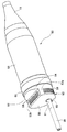
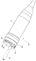
- the perspective view which shows the connector for endoscopes which concerns on the 1st Embodiment of this invention The perspective view which shows the structure of the connector for endoscopes seen from the angle different from FIG.
- the perspective view which shows the whole structure of an endoscope apparatus The perspective view which shows the external appearance of a processor.
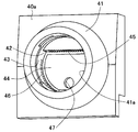
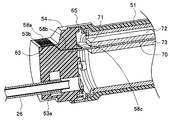
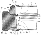
- the perspective view which shows the receptacle part 41 in FIG. The perspective view which shows the cross-sectional shape of an endoscope connector. Sectional drawing which shows the structure of an endoscope connector.
- FIG. 1 is a perspective view showing an endoscope connector according to a first embodiment of the present invention.
- FIG. 2 is a perspective view showing the configuration of the endoscope connector as viewed from an angle different from that in FIG.
- FIG. 3 is a perspective view showing the overall configuration of the endoscope apparatus.
- FIG. 4 is a perspective view showing the external appearance of the processor.
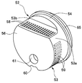
- FIG. 5 is a perspective view showing the configuration of the endoscope connector.
- FIG. 6 is a perspective view showing the receptacle 41 in FIG.
- FIG. 7 is a perspective view showing the cross-sectional shape of the endoscope connector
- FIG. 8 is a cross-sectional view showing the configuration of the endoscope connector.
- the endoscope apparatus 1 includes an insertion portion 2 as an elongated member to be inserted into a site to be observed, for example, a lumen such as the large intestine, and a base end portion of the insertion portion 2.
- the operation unit 3 provided, the universal cable 4 which is a composite cable extending from the side surface of the operation unit 3, and the external device which is provided at the end of the universal cable 4 and which is the light source device and the processor 40
- an endoscope connector hereinafter simply referred to as a connector
- the light source device and the processor may be integrated (see FIG. 4).
- the insertion portion 2 of the endoscope apparatus 1 has a distal end portion 6 in which an imaging portion using a CCD, a CMOS sensor, or the like is built in on the distal end side, and a bending portion as a movable portion that can be bent at the rear portion of the distal end portion 6.
- the part 7 is continuously provided.
- a long and flexible flexible tube portion 8 formed of a soft tubular member is connected to the rear portion of the curved portion 7.
- the proximal end portion of the flexible tube portion 8 of the insertion portion 2 is connected to the bend preventing portion 9 of the operation portion 3.
- the operation unit 3 includes a gripping unit 10 that a user grips when in use, and a treatment instrument insertion port 11 that constitutes a proximal end opening of a treatment instrument channel (not shown) disposed in the insertion unit 2. It is provided in the connecting part of the bend preventing part 9 and the grip part 10.
- the grip portion 10 of the operation portion 3 performs a bending operation of the bending portion 7 of the insertion portion 2.
- a bending operation unit 17 having a fixing lever 16 is disposed.
- the grip unit 10 is provided with switches 13 and 14 for operating various endoscope functions.
- the universal cable 4 of the endoscope apparatus 1 is folded to prevent damage due to twisting while maintaining the connection strength so as to cover the outer peripheral portion of the operation unit 3 or both ends connected to the connector 50. Stop members 18 and 19 are provided. A connector 50 is attached to the terminal member 19 of the universal cable 4.
- the connector 50 is connected to the receptacle 41 of the processor 40 of FIG. 4.
- the universal cable 4 side is the base end side (or the connector 50 side). The description will be made assuming that the side connected to the processor 40 is the front end side (or the rear side).
- the connector 50 includes a plug portion 52 provided on the distal end side and a connector case 51 provided on the proximal end side.
- the connector case 51 is formed in a substantially cylindrical shape having a diameter and size that can be easily grasped by an operator's hand, but the proximal end has a diameter toward the front so as to match the outer shape of the anti-bending member 19.
- the case body is slightly thinner.
- the receptacle portion 41 of the processor 40 is electrically connected by inserting the plug portion 52 of the connector 50.
- the outer shape of the plug portion 52 and the inner shape of the receptacle portion 41 are provided. Is configured to substantially match.
- the direction of the cylindrical central axis of the connector case 51 (the central axis of the connector 50) is the direction in which the connector 50 is inserted into the receptacle 41.
- the plug portion 52 has a fitting portion 53 provided with electrical contacts (connector contacts) 58 and 59 constituting a conductive portion on the distal end side, and a connecting portion 54 connected to the connector case 51 on the proximal end side.
- the fitting portion 53 and the connection portion 54 are integrally formed, and a flange portion 65 is formed at the distal end side end portion of the connector case 51 and the proximal end side end portion of the connection portion 54. The fitting state with the receptacle part 41 is maintained by the flange part 65.
- connection portion 54 is formed so that the proximal end side has substantially the same outer peripheral shape as the outer peripheral shape of the distal end side of the connector case 51.
- the case 51 is fixed to each other.
- connection portion 54 and the connector case 51 may be configured to be fixed to each other with a screw or the like at a predetermined position inside with an O-ring 64 (see FIG. 8) for maintaining watertightness interposed therebetween. .
- a pressure member such as a screw attached to the base end portion of the frame protruding from the base end side opening of the connector case 51 by attaching the tip of a frame (not shown) housed in the connector case 51 to the connection portion 54 with a screw or the like.
- the connector case 51 and the connection portion 54 may be connected in a watertight manner by pressing the connector case 51 toward the connection portion 54 via the O-ring 64.
- the method for watertightly connecting the connector case 51 and the connection portion 54 is not particularly limited.
- the fitting portion 53 has a shape in which a part of a columnar shape similar to that of the connection portion 54 is cut out, and a portion having a peripheral surface shape similar to that of the connection portion 54 (hereinafter, A circumferential portion 53a and a planar portion 53b parallel to the cylindrical central axis (hereinafter simply referred to as the central axis) direction of the connector case 51;
- the rear end surface of the fitting portion 53 is a flat surface (hereinafter, referred to as a front end surface) 56 orthogonal to the central axis, and the front end surface 56 forms a flat surface portion 53b so that a circle is partially cut off. It has a shape.
- an electrical contact (connector contact) 59 is provided on the circumferential portion 53a of the fitting portion 53, and an electrical contact (connector contact) 58 is provided on the flat portion 53b.
- a plurality of connector contacts 59 are arranged in parallel on a part of the circumferential surface of the circumferential portion 53 a so as to have a predetermined length in the central axis direction of the connector case 51.
- the connector contact 58 has a predetermined length in a short direction of the flat surface portion 53b that is the central axis direction of the connector case 51 on a part of the surface of the flat surface portion 53b, and extends in the longitudinal direction of the flat surface portion 53b.
- a plurality are arranged side by side.
- a notch 60 is formed on the edge of the circumferential portion 53 a of the fitting portion 53 so that the processor 40 recognizes the endoscope apparatus 1.
- an opening 61 is provided in the distal end surface 56 of the fitting portion 53 that is the distal end surface of the plug portion 52, and the light guide 26 is inserted into the opening 61.
- the connector 50 is connected to the receptacle 41 provided on the front surface 40a of the processor 40 shown in FIG.
- the connector 50 is inserted and inserted into the hole 41 a of the receptacle 41 of the processor 40, thereby connecting the connector 50 and the receptacle 41.
- a panel unit 49 for operating the processor 40 and displaying the status of the processor 40 is provided on the front surface 40a of the processor 40.
- the receptacle 41 of the processor 40 is provided with a metal mounting portion (not shown) at a predetermined position of the hole 41a.
- the flange portion 65 of the connector 50 is fitted and fixed to the mounting portion.
- the flange portion 65 and the mounting portion made of metal are connected to each other so that the endoscope device 1 and the ground of the processor 40 are connected to each other.
- the mounting portion only needs to have a metal portion for connection to the ground, and may be fitted and fixed by a non-metallic member.
- a movable shutter may be provided to prevent the user from contacting each receptacle contact.
- the inside of the hole portion 41 a has a shape that substantially matches the outer shape of the fitting portion 53 of the connector 50. That is, in the hole portion 41a, a flat surface 44 that is a surface perpendicular to the insertion direction of the connector 50 and has substantially the same shape and size as the distal end surface 56 of the fitting portion 53, and a circumferential portion of the fitting portion 53
- the inner peripheral surface portion 43 has substantially the same shape and size as 53a
- the flat portion 42 is a flat surface perpendicular to the flat surface portion 44 and has substantially the same shape and size as the flat surface portion 53b of the fitting portion 53.
- the fitting portion 53 of the connector 50 By inserting the fitting portion 53 of the connector 50 into the hole 41a, the circumferential portion 53a and the flat portion 53b of the fitting portion 53 face the inner peripheral surface portion 43 and the flat portion 42, respectively, and the fitting portion 53 is inserted. And the hole 41a are fitted.
- the planar portion 42 is provided with a plurality of electrical contacts (hereinafter referred to as receptacle contacts) 45 at positions corresponding to the plurality of connector contacts 58 provided on the planar portion 53b.
- a plurality of electrical contacts (receptacle contacts) 46 are provided at positions corresponding to the plurality of connector contacts 59 provided on the circumferential portion 53a.
- each connector contact 58 and each receptacle contact 45 are brought into contact with each other and are electrically connected. Connection is made, and each connector contact 59 and each receptacle contact 46 come into contact with each other to make electrical connection.
- the endoscope apparatus 1 and the processor 40 can exchange various signals.
- the light guide 26 protruding from the opening 61 of the connector 50 is inserted into the opening 47 provided in the flat portion 44.
- the illumination light transmitted from the illumination light source such as a halogen lamp in the processor 40 can be guided into the endoscope apparatus 1 through the light guide 26.
- the connector contacts 58 and 59 and the light guide 26 are disposed inside the fitting portion 53.
- the inside of the fitting part 53 is filled with resin 63 in most parts except for the part through which the connector contacts 58 and 59 and the light guide 26 are inserted.
- the arrangement of the connector contacts 58 and 59 is fixed by the resin 63, and the connector contacts 58 and 59 are insulated from each other.
- a circuit board 70 is arranged along a central axis and supported by a support member (not shown). At a predetermined position of the resin 63, a recess having an opposing surface parallel to the flat portion 53b is provided at an interval corresponding to the thickness of the circuit board 70, and the front end side of the circuit board 70 is fitted into the recess. ing. That is, the substrate surface of the circuit board 70 is parallel to the flat portion 53b. A board terminal 71 corresponding to each connector contact 58 is provided on the front surface of the circuit board 70.
- a circuit portion 72 made up of a plurality of circuit components is disposed on the surface of the circuit board 70 on the side where the board terminals 71 are formed.
- a circuit portion 73 made up of a plurality of circuit components is disposed on the surface of the circuit board 70 opposite to the board terminal 71 formation side.
- the circuit unit 72 is a circuit unit for high-speed transmission suitable for transmission of, for example, a video signal
- the circuit unit 73 is a circuit unit other than for high-speed transmission.
- the circuit unit for high-speed transmission and the circuit unit other than for high-speed transmission may be arranged on the substrate and may be arranged other than the above arrangement.
- the connector contact 58 is formed by bending, for example, a metal plate-like member having a long and constant width into a predetermined shape in the longitudinal direction, and a linear contact portion 58a exposed to the outside in the plane portion 53b.
- the conductive portion 58b is bent according to the position of the circuit board 70 (the distance between the flat portion 53b and the plane of the substrate 70), and the contact portion 58c is in contact with the board terminal 71 of the circuit board 70.
- the connector contacts 58 have the same shape, and the connector contacts 58 are arranged in parallel and at the same interval. Further, the longitudinal direction of each connector contact 58 coincides with the central axis direction.
- the substrate terminals 71 are arranged in a direction parallel to the arrangement direction of the contact portions 58a on the flat surface portion 53b in a state where the circuit board 70 is fitted in the resin 63. Is the same as the interval between the connector contacts 58.
- the contact portions 58c of the connector contacts 58 can be configured to contact the board terminals 71, respectively.
- the distance between the contact portion 58a of each connector contact 58 and the corresponding board terminal 71 is the same for any connector contact 58, and the shape and size of each connector contact 58 are the same. Therefore, the impedance between each contact portion 58 a and the corresponding board terminal 71 is the same for any connector contact 58.
- each connector contact 58 is formed of a material having excellent electrical characteristics and is directly connected to the board terminal 71, and other wiring material or the like is used for connection between each connector contact 58 and each board terminal 71. Since there is no need to use it, signal transmission through the connector contact 58 is extremely excellent in transmission characteristics, and high-speed transmission is possible.
- the connector contact 58 is used for transmitting a video signal.
- the video signal obtained by the imaging unit at the tip of the insertion unit 2 is transmitted to the circuit unit 72 mounted on the circuit board 70 in the connector case 51 of the connector 50 via the insertion unit 2, the operation unit 3, and the universal cable 4.
- the circuit part 72 transmits the video signal from the board terminal 71 to the circuit of the processor 40 via the connector contact 58 and the receptacle contact 45. Transmitted to the department. Since the transmission characteristics between the board terminal 71 and the connector contact 58 are good, the circuit unit 72 can perform high-speed transmission with the processor 40, which is an external device, and can transmit a high-resolution video signal or the like without transmission errors. It is possible to transmit.
- the connector contact 59 is used for purposes other than high-speed transmission.
- the connector contact 59 is used for power transmission, control, and information transmission.
- the connector contact 59 is formed by bending, for example, a thin plate-like member made of metal, for example, into a predetermined shape in the longitudinal direction, and a linear contact portion 59a exposed to the outside at the circumferential portion 53a.
- the conductive portion 59b is bent according to the position of the terminal 75a of the transmission board 75, and the contact portion 59c is in contact with the terminal 75a of the transmission board 75.
- a connector 75 b connected to each terminal 75 a is provided on the substrate 75, and this connector 75 b is connected to a connector 73 a provided on the circuit substrate 70 via a cable 77. In this way, conduction between each circuit of the circuit unit 73 mounted on the circuit board 70 and each connector contact 59 is achieved.
- FIG. 8 shows an example in which the connector contact 59 is connected to the connector 73a of the circuit board 70 via the board 75, but each connector contact 59 is directly connected to a terminal on the circuit board 70. You may do it. 8 shows an example in which all connector contacts 59 are connected to the connector 73a of the circuit board 70. However, part or all of the connector contacts 59 may be connected to the circuit board 70 in the endoscope apparatus 1. You may make it connect to other circuit parts other than.
- the fitting portion is provided with a flat portion formed in a shape obtained by cutting out a part of the cylindrical shape, and the connector contact is provided on the flat portion in a direction perpendicular to the central axis of the connector.
- the board provided with the board terminals in the direction parallel to the connector contact arrangement direction is arranged in the direction parallel to the central axis, and the distance from the contact part of the connector contact with the external device to the board terminal is determined for all connectors.
- the connector contact can be directly connected to the board terminal, and the impedance from the contact portion to the board terminal is made the same for all connector contacts, thereby improving the transmission characteristics and enabling high-speed transmission. .
- the connector contact that cannot be arranged only by the plane portion is arranged using the circumferential portion of the fitting portion, and by using this connector contact for transmission that does not require high-speed transmission, It is possible to arrange a sufficient number of connector contacts by effectively using the peripheral surface of the fitting portion.
- each connector contact is directly connected to the board terminal of the circuit board, and the impedance from the contact portion of each connector contact with the external device to the board terminal is set for all connectors. What is necessary is just to make it common in a contact. Considering that the circuit board is flat, it is considered that the arrangement direction of the connector contacts and the arrangement direction of the board terminals may be parallel. Therefore, in the above-described embodiment, the planar portion has been described as having a surface parallel to the central axis, but may be slightly inclined from the central axis. Furthermore, it is only necessary to match the impedances of the respective connector contacts. Therefore, by changing the wiring pattern, there may be cases where the arrangement of the connector contacts does not have to be somewhat parallel or the intervals need not be uniform. .
- the described requirements can be deleted if the stated problem can be solved and the stated effect can be obtained.
- the configuration can be extracted as an invention.
- the present invention by providing a flat portion in the fitting portion with the receptacle and arranging the connector contact on the flat portion, it is possible to directly connect the connector contact and the board terminal, thereby improving the transmission characteristics. It has the effect of being able to.
Landscapes
- Health & Medical Sciences (AREA)
- Life Sciences & Earth Sciences (AREA)
- Physics & Mathematics (AREA)
- Surgery (AREA)
- Optics & Photonics (AREA)
- Biomedical Technology (AREA)
- Animal Behavior & Ethology (AREA)
- Radiology & Medical Imaging (AREA)
- Nuclear Medicine, Radiotherapy & Molecular Imaging (AREA)
- Engineering & Computer Science (AREA)
- Biophysics (AREA)
- Heart & Thoracic Surgery (AREA)
- Medical Informatics (AREA)
- Molecular Biology (AREA)
- Pathology (AREA)
- General Health & Medical Sciences (AREA)
- Public Health (AREA)
- Veterinary Medicine (AREA)
- Astronomy & Astrophysics (AREA)
- General Physics & Mathematics (AREA)
- Endoscopes (AREA)
- Instruments For Viewing The Inside Of Hollow Bodies (AREA)
- Details Of Connecting Devices For Male And Female Coupling (AREA)
Abstract
Priority Applications (4)
| Application Number | Priority Date | Filing Date | Title |
|---|---|---|---|
| JP2016554751A JP6072389B1 (ja) | 2015-06-03 | 2016-04-12 | 内視鏡用コネクタ |
| EP16802922.1A EP3184028A4 (fr) | 2015-06-03 | 2016-04-12 | Connecteur pour endoscope |
| CN201680002655.XA CN107072519A (zh) | 2015-06-03 | 2016-04-12 | 内窥镜用连接器 |
| US15/485,463 US10624528B2 (en) | 2015-06-03 | 2017-04-12 | Connector |
Applications Claiming Priority (2)
| Application Number | Priority Date | Filing Date | Title |
|---|---|---|---|
| JP2015-113344 | 2015-06-03 | ||
| JP2015113344 | 2015-06-03 |
Related Child Applications (1)
| Application Number | Title | Priority Date | Filing Date |
|---|---|---|---|
| US15/485,463 Continuation US10624528B2 (en) | 2015-06-03 | 2017-04-12 | Connector |
Publications (1)
| Publication Number | Publication Date |
|---|---|
| WO2016194485A1 true WO2016194485A1 (fr) | 2016-12-08 |
Family
ID=57440870
Family Applications (1)
| Application Number | Title | Priority Date | Filing Date |
|---|---|---|---|
| PCT/JP2016/061814 Ceased WO2016194485A1 (fr) | 2015-06-03 | 2016-04-12 | Connecteur pour endoscope |
Country Status (5)
| Country | Link |
|---|---|
| US (1) | US10624528B2 (fr) |
| EP (1) | EP3184028A4 (fr) |
| JP (1) | JP6072389B1 (fr) |
| CN (1) | CN107072519A (fr) |
| WO (1) | WO2016194485A1 (fr) |
Families Citing this family (7)
| Publication number | Priority date | Publication date | Assignee | Title |
|---|---|---|---|---|
| US10916903B2 (en) * | 2018-02-04 | 2021-02-09 | Creganna Unlimited Company | System having a cable assembly and plug and receptacle connectors |
| CH715757A2 (de) * | 2019-01-17 | 2020-07-31 | Tecpharma Licensing Ag | Modulares Verabreichungsgerät für fluide Medikamentenformulierung. |
| CN110367910A (zh) * | 2019-08-23 | 2019-10-25 | 重庆金山科技(集团)有限公司 | 内窥镜接头、内窥镜镜体、内窥镜冷光源及内窥镜系统 |
| US11883002B2 (en) | 2021-09-09 | 2024-01-30 | Karl Storz Se & Co. Kg | Endoscope connector and endoscope adapter |
| DE102021123315B4 (de) | 2021-09-09 | 2026-01-29 | Karl Storz Se & Co. Kg | Anschlussadapteraufnahme für eine Lichtquelle zum Übertragen von Videosignalen von einem Videoendoskop zu einem mit der Lichtquelle verbindbaren Videoprozessor, Anschlussadapter für ein Videoendoskop, Lichtquelle, Videoendoskop, Videoprozessor und Videoendoskopsystem |
| CN115998223B (zh) * | 2023-01-31 | 2025-02-11 | 湖南省华芯医疗器械有限公司 | 一种内窥镜插入部用连接器及插入部的固定结构 |
| WO2025117855A1 (fr) * | 2023-11-29 | 2025-06-05 | Resnent, Llc | Ensemble endoscope modulaire |
Citations (2)
| Publication number | Priority date | Publication date | Assignee | Title |
|---|---|---|---|---|
| JPH06251829A (ja) * | 1993-02-24 | 1994-09-09 | Olympus Optical Co Ltd | コネクタ装置 |
| JPH06250103A (ja) * | 1993-02-24 | 1994-09-09 | Olympus Optical Co Ltd | コネクタ装置 |
Family Cites Families (25)
| Publication number | Priority date | Publication date | Assignee | Title |
|---|---|---|---|---|
| JPS5578932A (en) * | 1978-12-08 | 1980-06-14 | Olympus Optical Co | Connector for light guide cable of endoscope |
| JPS5670747A (en) * | 1979-11-15 | 1981-06-12 | Olympus Optical Co | Eyepiece apparatus of endoscope |
| JP2572394B2 (ja) * | 1987-03-19 | 1997-01-16 | オリンパス光学工業株式会社 | 電子内視鏡 |
| US5810620A (en) * | 1992-10-29 | 1998-09-22 | Olympus Optical Co., Ltd. | Electric connector provided with a shielding part for electrical contacts at the distal end of the plug |
| US5469841A (en) * | 1992-10-29 | 1995-11-28 | Olympus Optical Co., Ltd. | Endoscope apparatus provided with liquid removing mechanism for the electric connector |
| JP3245461B2 (ja) * | 1992-10-29 | 2002-01-15 | オリンパス光学工業株式会社 | 内視鏡装置 |
| JPH07184857A (ja) * | 1993-12-28 | 1995-07-25 | Olympus Optical Co Ltd | 内視鏡システム |
| US5564951A (en) * | 1994-02-23 | 1996-10-15 | Baxter International Inc. | Electrical cable connector and method of making |
| US5865726A (en) * | 1996-03-27 | 1999-02-02 | Asahi Kogaku Kogyo Kabushiki Kaisha | Front end structure of side-view type endoscope |
| US6211904B1 (en) * | 1997-09-11 | 2001-04-03 | Edwin L. Adair | Surgical devices incorporating reduced area imaging devices |
| US6043839A (en) * | 1997-10-06 | 2000-03-28 | Adair; Edwin L. | Reduced area imaging devices |
| US6982740B2 (en) * | 1997-11-24 | 2006-01-03 | Micro-Medical Devices, Inc. | Reduced area imaging devices utilizing selected charge integration periods |
| US20020098732A1 (en) * | 2001-01-19 | 2002-07-25 | Olympus Optical Co., Ltd. | Connector device for an endoscope |
| US7549958B2 (en) * | 2004-02-09 | 2009-06-23 | Olympus Corporation | Endoscope apparatus |
| JP4987257B2 (ja) * | 2005-06-29 | 2012-07-25 | オリンパス株式会社 | 内視鏡 |
| JP4762828B2 (ja) * | 2006-08-22 | 2011-08-31 | モレックス インコーポレイテド | 水密コネクタ及びその製造方法 |
| JP5178239B2 (ja) * | 2008-02-27 | 2013-04-10 | オリンパスメディカルシステムズ株式会社 | 医療用システム |
| US7632126B1 (en) * | 2008-05-23 | 2009-12-15 | Tyco Electronics Corporation | High density circular interconnect with bayonet action |
| US9642513B2 (en) * | 2009-06-18 | 2017-05-09 | Endochoice Inc. | Compact multi-viewing element endoscope system |
| WO2011052408A1 (fr) | 2009-10-28 | 2011-05-05 | オリンパスメディカルシステムズ株式会社 | Connecteur pour appareil médical |
| JPWO2011114771A1 (ja) * | 2010-03-16 | 2013-06-27 | オリンパスメディカルシステムズ株式会社 | コネクタ接続システム |
| WO2011114957A1 (fr) * | 2010-03-16 | 2011-09-22 | オリンパスメディカルシステムズ株式会社 | Système connecteur |
| TW201201641A (en) * | 2010-06-18 | 2012-01-01 | Sun Wei Ren | Micro sensor |
| JP2015181096A (ja) * | 2014-03-04 | 2015-10-15 | ソニー・オリンパスメディカルソリューションズ株式会社 | 配線接続装置、カメラヘッド、及び内視鏡装置 |
| EP3257431A4 (fr) * | 2015-11-19 | 2018-12-12 | Olympus Corporation | Dispositif d'endoscope |
-
2016
- 2016-04-12 JP JP2016554751A patent/JP6072389B1/ja active Active
- 2016-04-12 WO PCT/JP2016/061814 patent/WO2016194485A1/fr not_active Ceased
- 2016-04-12 CN CN201680002655.XA patent/CN107072519A/zh active Pending
- 2016-04-12 EP EP16802922.1A patent/EP3184028A4/fr not_active Withdrawn
-
2017
- 2017-04-12 US US15/485,463 patent/US10624528B2/en active Active
Patent Citations (2)
| Publication number | Priority date | Publication date | Assignee | Title |
|---|---|---|---|---|
| JPH06251829A (ja) * | 1993-02-24 | 1994-09-09 | Olympus Optical Co Ltd | コネクタ装置 |
| JPH06250103A (ja) * | 1993-02-24 | 1994-09-09 | Olympus Optical Co Ltd | コネクタ装置 |
Non-Patent Citations (1)
| Title |
|---|
| See also references of EP3184028A4 * |
Also Published As
| Publication number | Publication date |
|---|---|
| US10624528B2 (en) | 2020-04-21 |
| JPWO2016194485A1 (ja) | 2017-06-22 |
| CN107072519A (zh) | 2017-08-18 |
| EP3184028A1 (fr) | 2017-06-28 |
| EP3184028A4 (fr) | 2018-05-16 |
| JP6072389B1 (ja) | 2017-02-01 |
| US20170215702A1 (en) | 2017-08-03 |
Similar Documents
| Publication | Publication Date | Title |
|---|---|---|
| JP6072389B1 (ja) | 内視鏡用コネクタ | |
| JP4916595B2 (ja) | 撮像ユニット | |
| JP5469867B2 (ja) | 撮像カテーテルアセンブリを有する内視鏡および内視鏡を構成する方法 | |
| JP5435957B2 (ja) | 内視鏡 | |
| US20180092512A1 (en) | Endoscope | |
| US20160331214A1 (en) | Endoscope | |
| JP2010012079A (ja) | 内視鏡 | |
| US20210290041A1 (en) | Distal end portion of endoscope and endoscope | |
| CN107405063A (zh) | 内窥镜装置 | |
| JP2017113417A (ja) | 内視鏡 | |
| CN107115088B (zh) | 内窥镜 | |
| US20130253271A1 (en) | Endoscope | |
| US20250134355A1 (en) | Endoscopy device having an electrical control system | |
| JP2000139927A (ja) | 超音波内視鏡装置 | |
| EP4728964A1 (fr) | Unité modulaire d'imagerie et endoscope | |
| US12453464B2 (en) | Endoscope processor and endoscope system including a connector for receiving a first or second type connector | |
| JP3902267B2 (ja) | 内視鏡 | |
| US12303108B2 (en) | Endoscope, distal end portion of endoscope, and insertion portion of endoscope | |
| US11690503B2 (en) | Endoscopic instrument | |
| JP5090044B2 (ja) | 超音波医療装置用コネクタ | |
| JP2001161642A (ja) | 内視鏡用コネクタ | |
| JP2020500617A (ja) | 携帯型内視鏡 | |
| US11076744B2 (en) | Method of manufacturing endoscope and endoscope | |
| JP4197796B2 (ja) | 電子内視鏡 | |
| WO2026004467A1 (fr) | Connecteur ultrasonore, endoscope et système d'endoscope |
Legal Events
| Date | Code | Title | Description |
|---|---|---|---|
| ENP | Entry into the national phase |
Ref document number: 2016554751 Country of ref document: JP Kind code of ref document: A |
|
| 121 | Ep: the epo has been informed by wipo that ep was designated in this application |
Ref document number: 16802922 Country of ref document: EP Kind code of ref document: A1 |
|
| REEP | Request for entry into the european phase |
Ref document number: 2016802922 Country of ref document: EP |
|
| WWE | Wipo information: entry into national phase |
Ref document number: 2016802922 Country of ref document: EP |
|
| NENP | Non-entry into the national phase |
Ref country code: DE |