WO2016194703A1 - 被処理物の処理装置 - Google Patents
被処理物の処理装置 Download PDFInfo
- Publication number
- WO2016194703A1 WO2016194703A1 PCT/JP2016/065302 JP2016065302W WO2016194703A1 WO 2016194703 A1 WO2016194703 A1 WO 2016194703A1 JP 2016065302 W JP2016065302 W JP 2016065302W WO 2016194703 A1 WO2016194703 A1 WO 2016194703A1
- Authority
- WO
- WIPO (PCT)
- Prior art keywords
- workpiece
- holding
- processed
- shirt
- mounting plate
- Prior art date
- Legal status (The legal status is an assumption and is not a legal conclusion. Google has not performed a legal analysis and makes no representation as to the accuracy of the status listed.)
- Ceased
Links
Images


Classifications
-
- D—TEXTILES; PAPER
- D06—TREATMENT OF TEXTILES OR THE LIKE; LAUNDERING; FLEXIBLE MATERIALS NOT OTHERWISE PROVIDED FOR
- D06F—LAUNDERING, DRYING, IRONING, PRESSING OR FOLDING TEXTILE ARTICLES
- D06F89/00—Apparatus for folding textile articles with or without stapling
Definitions
- the present invention relates to a processing apparatus for processing an object to be processed such as a deformable thin object.
- Patent Document 1 a device for unfolding and folding deformable thin objects such as clothing.
- the present invention has been made in view of the above background, and an object of the present invention is to provide a processing apparatus capable of shortening the operation for holding and changing the workpiece and shortening the time for the folding process. To do.
- a processing apparatus that expands or folds an object to be processed, and has a movable area in a first area and is capable of holding the object to be processed.
- a third holding device having a movable range in the region and capable of holding the object to be processed below the placing device.
- the workpiece can be held by the third holding device while the workpiece is held by the first holding device and / or the second holding device.
- a part (for example, an end portion) of the object to be processed positioned below the placement device is moved to the third without moving the first holding device and / or the second holding device below the placement device.
- the third holding device holds the object to be processed in a state where the object to be processed is held by the first holding device and / or the second holding device and is hung from the placing device. You may make it hold
- the workpiece When the workpiece is hung from the mounting device, the workpiece is pulled and displaced in the horizontal direction (including cases where it has a horizontal component such as an oblique direction), so the overall height of the workpiece is vertical. Compared to the case of just lifting it, it becomes shorter (lowered). Accordingly, a larger object to be processed can be lifted (that is, the lowermost end of the object to be processed is separated from the bottom surface of the processing apparatus) by the first holding device and / or the second holding device. Or the height of the whole processing apparatus can be made small compared with the case where only the object to be processed is lifted in the vertical direction.
- the first holding device and / or the second holding device is moved below the mounting device for a part (for example, an end portion) of the object to be processed positioned below the mounting device. And can be held by the third holding device. As a result, the time required for holding can be shortened.
- the third holding device may deliver the held object to be processed to the first holding device or the second holding device below the placement device.
- first holding device or the second holding device may lift the delivered object to be moved upward along the placement device.
- the object to be processed is lifted upward along the mounting apparatus, and at this time, wrinkles, tangles, etc. of the object to be processed can be loosened.
- the first holding device has a pair of first gripping portions on its central axis
- the second holding device has a pair of second gripping portions on its central axis
- the third holding device has a pair of third gripping portions and a pair of fourth gripping portions, and the third gripping portion and the fourth gripping portion are arranged at equal intervals from the central axis of the third holding device. You may be made to do.
- the first holding device (second holding device) and the third holding device are arranged on the central axis in a state where the central axes are opposed to each other when the workpiece is delivered.
- a pair of first gripping portions (second gripping portions) of the first holding device (second holding device), a pair of third gripping portions and a pair of third holding devices arranged apart from the central axis And the fourth gripping portion are located at different positions. Accordingly, the delivery can be performed in a state in which the central axes of the first holding device (second holding device) and the third holding device are aligned with each other, so that drive control of each holding device is facilitated.
- the object to be processed is gripped at two points by the pair of third gripping portions and the pair of fourth gripping portions of the third holding device, and the center of these two gripping locations is first. Since it can hold
- the first holding device and / or the second holding device that holds the object to be processed is a stage in which the third holding device holds the object to be processed below the placing device. You may make it cancel
- the object to be processed T falls below the placement device, so that if the object to be processed is entangled, it can be loosened.
- the placing apparatus may be configured such that when the first holding device and / or the second holding device cancels the holding of the object to be processed, the object to be processed that has been rotated and dropped is dropped.
- the washing tub that is rotatably provided, a detection unit that detects an object to be processed in the laundry tub, and the laundry that holds the object to be processed detected by the detection unit.
- a holding device for taking out from the tub and a control device are provided, and the control device constitutes a processing device for rotating the washing tub before the holding device takes out the workpiece from the washing tub.
- the object to be processed rotates together with the washing tub, and the position, shape, etc. in the washing tub are caused by the rotational force and the weight of the object to be processed. Change.
- the object to be processed can be moved into the detectable range of the detection unit.
- the holding device exposes the parts that are easy to hold and the workpieces that are easy to hold, and holds the workpiece It can also be changed to a shape that is easy to do.
- the to-be-processed object in a washing tub can be detected and taken out correctly, and it can suppress that a to-be-processed object is left in a washing tub.
- the “laundry tub” is a container that accommodates an object to be washed, dehydrated or dried (hereinafter also referred to as “drying”). Or a device having at least one function of drying, for example, a device having only a washing / dehydrating function and a device having only a drying function, and not necessarily having all functions. Also provided).
- the “object to be processed” typically includes an object to be dried and the like, and the material, shape, size, and the like are not particularly limited.
- a deformable thin object represented by a cloth such as clothing and towels, a net (for example, a washing net) for housing these, and the like are included.
- the “holding device” may have a holding mechanism and can hold the workpiece.
- the holding mechanism includes a pair of finger members, and the pair of finger members are configured to approach or separate from each other.
- a hook on which an object to be processed is hung can be considered.
- the moving mechanism for making the holding mechanism movable includes a belt slider mechanism, a ball screw mechanism, an air cylinder mechanism, a motor cylinder mechanism, an electric slider mechanism, a linear slider mechanism, a rack and pinion mechanism, and the like.
- Mechanism. These mechanisms are mainly composed of a driving force source, a feed member, and a guide member.
- the belt slider mechanism is a slide moving mechanism using a motor as a driving force source, a belt or a wire as a feed member, and an LM guide material or the like as a guide member, and transmits the rotation of the motor to the belt or the wire to be moved. Is a mechanism that slides along a guide member such as an LM guide material.
- the ball screw mechanism is a slide moving mechanism that uses a motor as a driving force source, a ball screw or a trapezoidal screw as a feed member, and an LM guide material or the like as a guide member, and transmits the rotation of the motor to the ball screw or the trapezoidal screw.
- This is a mechanism for sliding a moving object along a guide member such as an LM guide.
- the air cylinder mechanism is a slide moving mechanism that uses an air compressor as a driving force source and a piston rod as a feeding member and a guide member, and is a moving object attached to the piston rod using the direct movement of the piston rod. Is a mechanism for moving the slide.
- the motor cylinder mechanism is a slide moving mechanism that uses a motor as a driving force source and a piston rod as a feeding member and a guide member, and transmits the rotation of the motor to a ball screw to move a moving object attached to the piston rod.
- This is a sliding mechanism.
- the electric slider mechanism is a slide moving mechanism that uses a motor as a driving force source, a ball screw or the like as a feed member, and an LM guide material or the like as a guide member, and transmits the rotation of the motor to the ball screw to move the moving object. This is a mechanism for sliding along a guide member such as an LM guide material.
- the linear slider mechanism is a slide moving mechanism that uses a magnet as a driving force source, the feed member as a magnet, and an LM guide material or the like as a guide member, and slides a moving object using the principle of a linear motor. It is a mechanism to move.
- the rack and pinion mechanism is a sliding mechanism that uses a motor as a driving force source, a rack and pinion as a feed member, and an LM guide material or the like as a guide member. The pinion is rotated by the rotation of the motor and attached to the rack. This is a mechanism for sliding the moved object along a guide member such as an LM guide material.
- control device may rotate the washing tub when the workpiece is not detected.
- the workpiece If the workpiece is not detected, it can be detected for the reason that the workpiece is not actually left in the washing tub, or that the workpiece remains but is in the blind spot of the detector. There was a case that it did not.
- the latter case can be detected by rotating the washing tub and shifting the position and shape of the object to be processed. Thereby, it can suppress that a to-be-processed object cannot be detected but leaves in a washing tub.
- control device may rotate the washing tub when the holding device cannot hold the workpiece.
- the laundry tub is rotated to change the position and shape of the object to be processed, and the positional relationship with other objects to be processed. It can be made easy to grasp by the holding device. Thereby, it can suppress that a to-be-processed object cannot be hold
- a folding device for unfolding and / or folding the taken-out workpiece may be provided.
- the object to be processed taken out from the washing tub is expanded (expands the object to be processed), recognized (recognizes the type and attribute of the object to be processed), folded (by the series of operations) by the folding device.
- Processing hereinafter also referred to as “folding” such as folding (according to the type and attribute of the object to be processed) and / or transporting (which may include sorting according to the attribute, type, etc. of the object to be processed). be able to.
- the object to be processed, which has been dried in the washing tub has a high temperature and a lot of air, and is in a soft state.
- the object to be processed can be accurately recognized and can be folded neatly.
- it may be removed from the washing tub after dehydration and folded, for example, without being dried.
- the “folding device” only needs to perform one or more processes such as folding, and includes, for example, a device that only unfolds the workpiece.
- the folding device and a washing / drying machine having the washing tub may be provided in a housing.
- the overall configuration can be made more compact.
- the washing and drying machine has a drying function, it is possible to raise the temperature inside the case by using heat discharged by drying, so that the temperature inside the case is kept higher even during folding, It is possible to continue drying the object to be processed during folding and the like, to reduce wrinkles of the object to be processed, and to fold the object cleanly.
- the folding device may be arranged above the washing / drying machine.
- the processing such as folding can be started by lifting the processing object taken out from the washing tub upward, and the processing object can be more easily transported. Further, when the washing / drying machine has a drying function, the heat discharged by drying rises upward, so that the folding device above the housing can easily use the heat.
- the casing may be provided with a ventilation device arranged above the washing and drying machine.
- the heat discharged from the washing / drying machine can be discharged to the outside, or air can be taken in from the outside, and the temperature in the housing can be kept in a suitable state.
- the ventilation device may perform natural ventilation in which air supply and / or exhaust is performed through a vent, or mechanical ventilation using a fan or the like for air supply and / or exhaust.
- the ventilation may be continuous operation or intermittent operation.
- the folding device may include the holding device or another holding device that holds the taken-out workpiece, and a placement device that can place the workpiece. .
- the object to be processed can be folded using the holding device or another holding device and the mounting plate.
- the folding device may further include a pair of clamping devices that move relative to the placement device and sandwich the placement device on which the workpiece is placed.
- the object to be processed can be creased by sandwiching the object to be processed placed on the placement device by the pair of clamping devices.
- the holding device or the other holding device, the placing device, or the clamping device may be provided with a plurality of vent holes for ejecting steam.
- the steam can be applied to the object to be processed by ejecting the steam from the vent during or before folding.
- the holding device, other holding device, mounting device, or holding device can be provided with the iron steam function.
- a heat transfer body may be provided inside the holding device or the other holding device, the mounting device, or the clamping device.
- the ironing function can be provided by raising the surface temperature of the holding device or other holding device, the mounting device or the clamping device by the heat transfer body. Thereby, the wrinkles of the object to be processed can be reduced, and a beautiful crease can be given to the object to be processed.
- the “heat transfer body” may be anything that transfers heat to the mounting device or the clamping device.
- it may be a heating wire that generates heat, or it may be constituted by a pipe or the like through which a fluid whose temperature is adjusted.
- the folding device may include a storage unit that stores the object to be processed and is movable up and down in the housing.
- the storage unit can be moved up and down in the housing, so that the storage unit can be moved to an optimal position according to processing. For example, during folding, the storage unit is moved to the uppermost or lowermost part of the housing so as not to obstruct the movement of the holding device, the mounting plate, etc. For example, it is possible to move the upper body of the user to the height of the waist and to easily take out the workpiece.
- the washing / drying machine may be a drum type.
- the drum-type washing and drying machine lifts the object to be processed and drops it down when drying, etc., so that air enters the object and feels soft (the object to be processed does not shrink). Also, it is difficult to wrinkle. Therefore, it becomes easy to take out the object to be processed from the washing tub, and the processing such as folding is easy, so that it can be suitably used with the folding device.
- the door of the washing tub may be provided on the upper surface of the washing / drying machine.
- the object to be processed can be taken out from the washing tub by lifting the object to be processed from above by the holding device. Therefore, it is possible to prevent the object to be processed from being caught on other structures of the washing / drying machine at the time of taking out, and it becomes easier to take out the object to be processed and the structure of the holding device is also simpler. be able to.
- the door of the washing tub may be provided on a side surface of the washing / drying machine and configured to slide downward and open.
- the door of the washing tub is provided on the side surface of the dryer, the object to be processed can be put into the washing tub from the side surface of the housing. Moreover, since it is comprised so that a door may slide and open below, the magnitude
- the detection unit may include a digital still camera, an infrared camera, an infrared sensor, an ultrasonic sensor, or a projector.
- the shape, size, arrangement between the objects to be processed, and the like can be detected by the digital still camera, the infrared camera, the infrared sensor, the ultrasonic sensor, or the projector.
- the detection unit may be provided on the holding device.
- the detection unit can move to the inside of the washing tub together with the holding device, for example, even when the object to be processed is stuck on one corner of the washing tub, It is possible to detect the workpiece and more accurately detect the workpiece.
- the present invention it is possible to provide a processing apparatus capable of shortening the operation required for holding and changing the object to be processed and reducing the time required for the folding process.
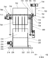
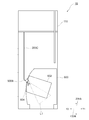
- FIG. 1 is a perspective view of a processing apparatus 1.
- FIG. 3 is a perspective view of a receiving and conveying device in the processing apparatus 1. It is a perspective view of the receiving conveyance apparatus, the clamping apparatus, and the conveyance apparatus in the processing apparatus.
- 3 is a perspective view of a holding device in the processing apparatus 1.
- FIG. It is a perspective view of the holding mechanism. It is a perspective view of the holding mechanism.
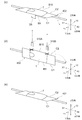
- 2 is a perspective view of a mounting device in the processing apparatus 1.
- FIG. (A) It is the figure which looked at the front from the inside of a processing apparatus which shows the conveying apparatus in the processing apparatus 1.
- FIG. (B) It is a side view which shows a supporting member.
- 3 is a functional block diagram of a control device in the processing device 1.
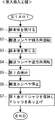
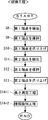
- FIG. It is a figure explaining "folding information" about T-shirts as an example of a processed object. It is the flowchart which showed the acceptance delivery process of the T-shirt by the processing apparatus 1 shown in FIG. It is the flowchart which showed the recognition process of the T-shirt. It is the flowchart which showed the folding process of the T-shirt. It is the flowchart which showed the conveyance process of the T-shirt. It is a figure for demonstrating the processing operation of the T-shirt. It is a figure for demonstrating the processing operation of the T-shirt. It is a figure for demonstrating the processing operation of the T-shirt. It is a figure for demonstrating the processing operation of the T-shirt.
- FIG. It is a schematic diagram for demonstrating the structure of the processing apparatus 1B. It is a functional block diagram about the control apparatus in the processing apparatus 1B. It is a figure for demonstrating the taking-out process of to-be-processed object T.
- FIG. It is a figure for demonstrating the steam function of the mounting apparatus which concerns on a modification (AA). It is a figure for demonstrating the steam function of the clamping apparatus which concerns on a modification (AA). It is a figure for demonstrating the steam function of the holding
- the processing apparatus 1 is an apparatus for holding, recognizing, folding, and transporting the workpiece T as a deformable thin object. As shown in FIG. 1, the processing apparatus 1 is roughly a frame 100, a receiving transport apparatus 200, Holding devices 300A and 300B, a mounting device 400, an imaging device 500, a clamping device 700, a transport device 800, and a control device 900 (FIG. 10) are provided.
- the to-be-processed object T is a deformation
- the shape may be a rectangle like towels. However, it may be substantially rectangular like a T-shirt or a running shirt.
- the frame 100 includes four frame frames 102 and a frame base 104 provided at the lower part of the frame frame 102. Further, the upper ends of the frame frames 102 adjacent in the front-rear direction (arrow Y direction) are connected by a horizontal frame frame 105. Further, wall surfaces are provided between the frame frames 102, respectively. As a result, a closed internal space is formed in the processing apparatus 1.
- the wall surface to which the door body 210 is attached is referred to as the front surface 106A
- the wall surface facing this is referred to as the back surface 106B
- the right wall surface is referred to as the right side surface 106C
- the left wall surface is referred to as the left side surface 106D.
- the frame and the wall surface are also referred to as a “casing”.
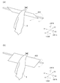
- the receiving and conveying apparatus 200 is an apparatus for receiving the workpiece T from the outside, and includes a door 202 (FIG. 2) and a conveying conveyor 204 (FIG. 3) as shown in FIGS. Yes.
- the receiving / conveying device 200 is connected to a control device 900 described later so as to be communicable by wire or wirelessly.
- the operation of the conveyor 204 is controlled by the control device 900.
- the door 202 is disposed slightly below the center of the front surface 106A of the processing apparatus 1 that is easily accessible by the user. As shown in FIG. 2, the door 202 includes a door main body 210, a door shaft 212, a pair of door shaft holding members 214, a door opening / closing motor 216, a door opening / closing motor power transmission means 218, The object receiving member 220 and the obstacle member 222 are provided.
- the door main body 210 is a rectangular plate material for opening and closing the opening O (FIG. 1) formed in the front surface 106 ⁇ / b> A of the processing apparatus 1.
- the door shaft 212 is attached to the lower end portion of the door main body 210 so that the rotation axis thereof is along the width direction (arrow X direction).
- the pair of door shaft holding members 214 rotatably hold both ends of the door shaft 212.
- Each door shaft holding member 214 is attached to the back side of the front surface 106A.
- the door opening / closing motor 216 is a motor capable of normal rotation and reverse rotation, and is attached in the vicinity of the opening O on the back surface of the front surface 106A.
- the door opening / closing motor power transmission means 218 includes a driving pulley 224, a driven pulley 226, and a belt 228.
- the driving pulley 224 is attached to the output shaft end of the door opening / closing motor 216.
- the driven pulley 226 is attached in the vicinity of the door opening / closing motor 216 on the door shaft 212.
- the belt 228 is stretched between the driving pulley 224 and the driven pulley 226.
- the turning force of the door opening / closing motor 216 is transmitted to the door shaft 212 via the door opening / closing motor power transmission means 218.
- the door shaft 212 rotates about the rotation shaft
- the door main body 210 rotates about the door shaft 212.
- the opening O is opened and closed.
- the workpiece receiving member 220 includes a pair of side plates 230, a bottom plate 232, and a back plate 234.
- the workpiece receiving member 220 is attached to the inner surface of the door main body 210.
- a space for receiving the workpiece T to be processed is formed on the back side of the door main body 210.
- an object receiving box R is arranged.
- a basket may be used, or the processed workpiece T may be placed directly on the bottom plate 232.
- the obstruction member 222 is a long member having an arc-shaped cross section and extending in the width direction (arrow X direction).
- the height (in the arrow Z direction) of the obstruction member 222 can be set as appropriate. For example, it is approximately the same as or slightly larger than the diameter (for example, 10 to 20 mm) of the grip member 328 (see FIG. 6) of the substantially disk of the holding mechanism 322. It is preferable to be provided. As a result, the object to be processed that has climbed over the obstacle member 222 can be gripped by the entire surface of the gripping member 328 of the holding mechanism 322. Also, one end of a pair of support members 236 is connected to the back surface of the obstacle member 222 (a convex surface facing the door body 210).
- the other ends of the support members 236 are connected to the lower ends of the side plates 230 that constitute the workpiece receiving member 220, respectively.
- the obstacle member 222 is disposed substantially parallel to the door main body 210 at a position deeper than the workpiece receiving member 220.
- the transport conveyor 204 is disposed directly below the workpiece receiving member 220 in a state where the door body 210 is closed.
- the conveyor 204 includes four support frames 238 erected substantially vertically from the frame base 104, a pair of rollers 240, a conveyor belt 242, a conveyor drive motor 244, and a conveyor drive motor power transmission means 246. I have.
- the pair of rollers 240 is rotatably installed between the pair of support frames 238 so that the rotation axis thereof is along the width direction (arrow X direction).
- the position of each roller 240 in the height direction is such that the line connecting the upper ends of the surfaces of both rollers 240 is slightly separated from the lower end of the obstacle member 222 in a state where the door body 210 is closed, rather than the thickness of the conveyor belt 242. It is set to be. Therefore, the lower end of the obstruction member 222 is located in the vicinity of the upper surface of the conveyor belt 242 with the door body 210 closed.
- the conveyor belt 242 is stretched between a pair of rollers 240.
- the conveyor drive motor 244 is a motor capable of normal rotation and reverse rotation, and is attached to the upper surface of the frame base 104 as shown in FIG.
- the conveyor drive motor power transmission means 246 includes a drive pulley 248, a driven pulley 250, and a belt 252.
- the drive pulley 248 is attached to the output shaft end of the conveyor drive motor 244.
- the driven pulley 250 is attached to one roller 240.
- the belt 252 is bridged between the driving pulley 248 and the driven pulley 250.
- the rotational force of the conveyor drive motor 244 is transmitted to one of the rollers 240 (the roller 240 disposed immediately below the door 202) via the conveyor drive motor power transmission means 246.
- the conveyor belt 242 also rotates in the same direction.
- the rotation direction (forward / reverse direction) of the conveyor drive motor 244 is controlled by the control device 900.
- the rotation that causes the conveyor belt 242 to move away from the door body 210 is referred to as “forward rotation”
- the rotation that approaches the door body 210 is referred to as “reverse rotation”.
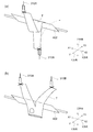
- the holding device 300 is a device that recognizes and folds the workpiece T in cooperation with the mounting device 400 while holding and pulling up the workpiece T placed on the transport conveyor 204 of the receiving transport device 200. is there. (At least the conveyance conveyor 204, the obstacle member 222, and the holding device 300 described above constitute a holding system for the workpiece T).
- the processing apparatus 1 includes a pair of holding devices 300A and 300B, and each holding device 300A and 300B includes holding mechanisms 310A and 310B and moving mechanisms 320A and 320B, respectively. .
- maintenance apparatus 300A, 300B is arrange
- the branch device “A” is assigned to the holding device and its components closer to the door 202, and the branch device “B” is attached to the holding device and its components far from the door 202 for distinction. To do.
- the pair of holding devices 300 ⁇ / b> A and 300 ⁇ / b> B can move relative to the mounting device 400 in the vertical direction (Z direction), the width direction (X direction), and the front-rear direction (Y direction).
- the holding devices 300 ⁇ / b> A and 300 ⁇ / b> B can be aligned so that they are aligned on the same line (the same height) as the edge of the mounting plate 402 of the mounting device 400, and one holding device 300 ⁇ / b> A is arranged from the mounting plate 402.
- the other holding device 300B can be moved freely within the movable range, for example, so that the other holding device 300B is located behind the mounting plate 402.
- the mounting device 400 is disposed within the movable range of the holding device 300.
- the holding device 300B will be described with reference to FIG. Note that the configuration of the holding device 300A is basically the same as the configuration of the holding device 300B, and therefore, the description thereof is omitted by using a reference numeral in which “B” is replaced with “A” in the reference numeral of the holding device 300A.
- the holding mechanism 310B holds a part of the workpiece T. Further, the moving mechanism 320B moves the holding mechanism 310B.
- the holding device 300B is connected to a control device 900, which will be described later, in a communicable manner by wire or wirelessly.
- the control device 900 controls operations of the holding mechanism 310B and the moving mechanism 320B.
- the holding mechanism 310B As the holding mechanism 310B, a holding mechanism that positively holds the workpiece T and a locking mechanism that simply holds the workpiece T are conceivable. In the processing apparatus 1 of the present embodiment, a holding mechanism is used as the holding mechanism 310B in the holding apparatus 300B. Therefore, in the following description, a case where the holding mechanism is a holding mechanism will be described.
- the holding mechanism 310B includes a pair of finger members 322B, a linear actuator 324B, and a rotary actuator 326B, as shown in FIGS. 6 shows a state in which the pair of finger members 322B are separated from each other, and FIG. 7 shows a state in which the pair of finger members 322B are in contact with each other. Furthermore, a substantially disc-shaped gripping member 328B is rotatably attached to the distal end portion of each finger member 322B.
- the linear actuator 324B is connected to the rotary actuator 326B via a connecting plate member 330B having an L-shaped cross section.
- the pair of finger members 322B have a role of gripping the workpiece T. More specifically, the gripping member 328B attached to the tip of each finger member 322B directly contacts the workpiece T and grips the workpiece T.
- the linear actuator 324B brings the pair of finger members 322B close to or away from each other.
- one finger member 322B is fixed to the linear actuator 324B, and the other finger member 322B moves in accordance with the operation of the linear actuator 324B.
- the maximum width (opening / closing stroke) between the pair of finger members 322B can be set as appropriate.
- the rotary actuator 326B rotates the linear actuator 324B in the arrow R1 direction via the connecting plate member 330B, with the horizontal direction (arrow X direction) as the rotation axis.
- the moving mechanism 320B includes a width direction moving mechanism 332B, a pair of vertical direction moving mechanisms 334B, and a longitudinal direction moving mechanism 336B.
- the width direction moving mechanism 332B moves the holding mechanism 310B in the width direction (arrow X direction).
- the vertical movement mechanism 334B moves the holding mechanism 310B in the vertical direction (arrow Z direction) together with the width direction movement mechanism 332B.
- the front-rear direction moving mechanism 336B moves the up-down direction moving mechanism 334B, the width-direction moving mechanism 332B, and the holding mechanism 310B in the front-rear direction (arrow Y direction).
- the width direction moving mechanism 332B is provided to move the holding mechanism 310B in the width direction (arrow X direction).
- the width direction moving mechanism 332B includes a width direction moving motor 338B serving as a driving force source and a linear guide 340B.
- the linear guide 340B is inserted into the width direction moving motor 338B.
- the linear guide 340B has a round bar shape and is installed between a pair of left and right vertical movement plates 344BR and 344BL in the vertical movement mechanism 334B. That is, the linear guide 340B is arranged such that the longitudinal direction thereof is along the width direction (arrow X direction).
- the width-direction moving motor 338B slides along the linear guide 340B when energized.
- the rotary actuator 326B of the holding mechanism 310B is fixed to the width direction moving motor 338B. When the width direction moving motor 338B moves in the width direction (arrow X direction) along the linear guide 340B, the holding mechanism 310B fixed to the width direction moving motor 338B also moves in the width direction (arrow X direction).
- the vertical movement mechanism 334B moves the above-described width direction movement mechanism 332B in the vertical direction (arrow Z direction).
- the vertical movement mechanism 334B includes a pair of left and right vertical movement plates 344BR and 344BL and a pair of left and right lifting units 346BR and 346BL.
- a branch number “R” is attached to the vertical movement plate, the lifting unit and its components on the right side in front view
- a branch number “R” is assigned to the vertical movement plate, the lifting unit and its components on the left side in front view.
- L is distinguished.
- the configurations of the vertical movement plate 344BL and the lifting unit 346BL are basically the same as those of the vertical movement plate 344BR and the lifting unit 346BR. The description is omitted by using the reference numerals replaced with ".”
- the above-described width direction moving mechanism 332B is attached to the vertical movement plate 344BR.
- a vertical movement plate 344BR is attached to the lifting unit 346BR.
- the elevating unit 346BR is attached to a frame body 348BR, which will be described later, in the longitudinal movement mechanism 336B.
- the elevating unit 346BR has a vertical driving motor 350BR, a ball screw 352BR, and a nut 354BR as a driving force source.
- the vertical drive motor 350BR is a motor capable of normal rotation and reverse rotation.
- the vertical driving motor 350BR is fixed to the lower part of the frame 348BR of the front-rear direction moving mechanism 336B.
- the ball screw 352BR is disposed along the vertical direction (arrow Z direction) so as to receive the driving force from the vertical driving motor 350BR.
- the nut 354BR is screwed to the ball screw 352BR, and moves in the vertical direction (arrow Z direction) as the ball screw 352BR rotates. Further, the vertical movement plate 344BR is fixed to the nut 354BR.
- the vertical drive motor 350BR of the elevating unit 346BR When the vertical drive motor 350BR of the elevating unit 346BR is driven, the ball screw 352BR rotates. Then, when the nut 354BR screwed to the ball screw 352BR moves in the rotation axis direction (arrow Z direction) of the ball screw 352BR, the vertical movement plate 344BR attached to the nut 354BR moves in the rotation axis direction (arrow Z direction). To do. When the vertical driving motors 350BR and 350RL operate in synchronization, the width direction moving mechanism 332B moves along the vertical direction (arrow Z direction).
- the front-rear direction moving mechanism 336B is a pair of left and right mechanisms that move the above-described vertical direction moving mechanism 334B in the front-rear direction (arrow Y direction).
- the front-rear direction moving mechanism 336B includes a frame 348B, a plurality of slide guides 356B, a front-rear direction driving motor 358B, and a linear guide 360B.
- the vertical movement mechanism 334B described above is attached to the frame 348B.
- a branch number “R” is attached to the front-rear direction moving mechanism 336B and its components on the right side when viewed from the front
- a branch number “L” is assigned to the front-rear direction moving mechanism 336B and its components on the left side when viewed from the front.
- the configuration of the longitudinal movement mechanism 336BL is basically the same as the configuration of the longitudinal movement mechanism 336BR, and therefore, by using a symbol in which “R” is replaced with “L” in the symbol of the longitudinal movement mechanism 336BR, The description is omitted.
- the slide guide 356BR guides the longitudinal movement of the longitudinal movement mechanism 336BR. Two sets of slide guides 356BR are used for one longitudinal movement mechanism 336BR.
- the slide guide 356BR has an LM guide 362BR and a slider 364BR.
- the LM guide 362BR is disposed on the inner surface of the right side surface 106C so that the longitudinal direction thereof is the front-rear direction (the arrow Y direction).
- Each of the sliders 364BR is attached to the frame body 348BR.
- the LM guide 362BR is also used for the slide guide 356AR in the moving mechanism 320A of the holding device 300A. That is, the LM guide 362AR and the LM guide 362BR are the same member.
- the linear guide 360BR is inserted into the front-rear direction drive motor 358BR.
- Two sets of longitudinal drive motors 358BR and linear guides 360BR are used for one longitudinal movement mechanism 336BR.
- One longitudinal driving motor 358BR is attached to the upper end of the frame 348BR.
- the other longitudinal driving motor 358BR is attached to the lower end of the frame 348BR.
- Each linear guide 360BR is arranged on the inner surface of the right side surface 106C so that the longitudinal direction thereof is the front-rear direction (arrow Y direction).
- the front-rear driving motor 358BR moves along the linear guide 360BR, the frame body 348BR also moves.
- the width direction moving mechanism 332BR and the holding mechanism 310B also move in the same manner.
- the linear guide 360BR is also used for the moving mechanism 320A of the holding device 300A. That is, the linear guide 360AR and the linear guide 360BR are the same member.
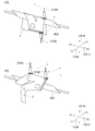
- the placement device 400 is a device that rotates and moves a placement plate 402 on which the workpiece T is placed during recognition processing and folding processing.
- the mounting device 400 generally includes a mounting plate 402, a pair of left and right frames 404R and 404L, a rotating mechanism 406, a front-rear direction moving mechanism 408, and a workpiece sensor 409.
- the mounting device 400 operates in conjunction with the movement of the holding device 300.
- the placement device 400 places, for example, the workpiece T that is held by the holding device 300 and hangs downward (arrow Z direction) on the placement plate 402 during the recognition process (the main surface of the placement plate 402). Or by hooking it on the edge), by pulling a part of the workpiece T in the horizontal direction and displacing it, the workpiece T is moved away from the bottom surface of the processing apparatus 1 in the vertical direction (arrow Z direction). Reduce the length (reduce the height). Thereby, the larger workpiece T can be lifted by the holding device 300 (that is, the lowermost end of the workpiece T is separated from the bottom surface of the processing device) and held.
- the mounting plate 400 folds the workpiece T by hooking the workpiece T on the edge of the mounting plate 402 during the folding process.
- the mounting plate 402 includes a mounting plate body 410 that is a substantially rectangular plate material and a rotating shaft 412.
- the rotating shaft 412 is fixed to the mounting plate main body 410 in a state of being eccentric from the center in the front-rear direction (Y direction) of the mounting plate main body 410 to either one of the long sides. Since the mounting plate main body 410 is arranged eccentrically with respect to the rotating shaft 412, the distance from the rotating shaft 412 to the long side of the mounting plate main body 410 is different for each long side. Thereby, for example, by bringing the workpiece T into contact with the long side on the longer distance side from the rotating shaft 412, the same inclination angle (for example, 60 degrees) can be obtained as compared with the case where the object T is not eccentric.
- the to-be-processed object T can be lifted highly, and the limited space in the processing apparatus 1 can be utilized more effectively.
- the rotation shaft 412 is formed longer than the mounting plate main body 410 and protrudes from both short sides of the mounting plate main body 410.
- the right end (in the arrow X1 direction) of the rotation shaft 412 is connected to the rotation center of the upper pulley 426 in the rotation mechanism 406 described later.
- the rotation shaft 412 is arranged so that the central axis thereof is in the left-right direction (arrow X direction). Further, the rotation of the rotating shaft 412 counterclockwise when viewed from the left side surface 106D is referred to as “forward rotation”. Conversely, the rotation of the rotating shaft 412 in the clockwise direction is referred to as “reverse rotation”.
- the pair of left and right frames 404R and 404L are members for holding the rotating shaft 412 so as to be rotatable at a predetermined height.
- the right frame 404R includes a rectangular parallelepiped hollow member 418 having a space inside and a bracket 420 (in FIG. 8, for convenience, the left side (arrow X2 direction) bracket 420 is removed. Is shown.)
- the bracket 420 is a substantially rhombus plate.
- a hollow member 418 is attached along the long axis of the bracket 420.
- a moving plate 416R is attached along the short axis of the bracket 420. Thereby, the hollow member 418 is erected from the moving plate 416R.
- a bearing 421 that rotatably holds the left end (in the direction of the arrow X2) of the rotation shaft 412 is provided at the upper end portion of the support column 419.
- the rotation mechanism 406 is a mechanism that rotates the mounting plate 402.
- the rotation mechanism 406 generally includes a rotation motor 422, a lower pulley 424, an upper pulley 426, and a belt 428.
- Rotating motor 422 generates a driving force that rotates mounting plate 402.
- the rotation motor 422 is fixed to the moving plate 416R.
- a rotating disk 430 is attached to the output shaft end of the rotation motor 422.
- the lower pulley 424 receives a driving force from the rotation motor 422.
- the lower pulley 424 is rotatably held by a substantially pulley-shaped lower pulley holding member 432.
- the output shaft of the rotation motor 422 and the rotation shaft of the lower pulley 424 are set to be orthogonal to each other.
- the rotation motor 422 and the lower pulley 424 are positioned so that the outer edge of the rotating disk 430 is in contact with the peripheral surface of the lower pulley 424. As a result, the driving force from the rotation motor 422 is transmitted to the lower pulley 424 while being shifted by 90 °.
- the tip of the rotating shaft 412 of the mounting plate 402 is attached to the center of the upper pulley 426.
- a belt 428 is bridged between the upper pulley 426 and the lower pulley 424.
- the driving force received from the rotation motor 422 is transmitted from the lower pulley 424 to the upper pulley 426 via the belt 428.
- the upper pulley 426 receiving the driving force rotates.
- the mounting plate 402 also rotates.
- the front-rear direction moving mechanism 408 includes a pair of left and right moving plates 416R, 416L, a connecting member 434 that connects the pair of left and right frames 404R, 404L to each other, a front-rear direction driving motor 436, and a linear guide 438. Yes.
- the front-rear direction moving mechanism 408 is disposed below the transfer conveyor 204 in the receiving transfer apparatus 200.
- the connecting member 434 connects the lower ends of the two frames 404R and 404L to each other on the lower side of the transport conveyor 204. That is, the connecting member 434 is a member that extends in the width direction (arrow X direction).
- a linear guide 438 is inserted into the front-rear direction drive motor 436.
- the front-rear direction drive motor 436 is attached to the lower side of the connecting member 434 described above via a bracket 440.
- the linear guide 438 is arranged such that its longitudinal direction is the front-rear direction (arrow Y direction).
- the front-rear direction driving motor 436 is attached to the lower side of the central portion of the connecting member 434.
- the connecting member 434 When the longitudinal driving motor 436 moves along the linear guide 438, the connecting member 434 also moves in the same direction. When the connecting member 434 moves, the frames 404R and 404L and the mounting plate 402 also move in the same direction.
- the workpiece sensor 409 is attached to the moving plate 416L on the surface of the moving plate 416R. That is, the workpiece sensor 409 is attached in a direction substantially orthogonal to the conveyor belt 242 in the transport conveyor 204. Thus, since the workpiece sensor 409 is attached to the moving plate 416R, when the mounting device 400 is moved in the front-rear direction by the front-rear direction moving mechanism 408, the object sensor 409 is also moved in the front-rear direction at the same time. .
- the workpiece sensor 409 is an obstacle detection sensor.
- an obstacle for example, the workpiece T
- the workpiece sensor 409 detects the obstacle and transmits an obstacle detection signal.
- the obstacle detection signal transmitted from the object sensor 409 is sent to the control device 900 via the signal line.
- the imaging device 500 is a device for detecting an end point or the like of the object to be processed T when receiving the object to be processed T, performing a conveying process, a recognition process, and a folding process, and at least the holding device 300 and the mounting device 400.
- the entire moving range of the camera can be imaged.
- the imaging device 500 includes a first imaging unit 502 and a second imaging unit 504. Digital still cameras are used as the imaging units 502 and 504, respectively.
- a wide-angle lens or a variable focus lens may be used as the digital still camera lens of the first imaging unit 502 and the second imaging unit 504.
- a larger object T can be imaged with one imaging unit.
- the material of the workpiece T may be detected from the texture of the workpiece T by the imaging units 502 and 504. If the material of the workpiece T can be grasped, gripping or folding suitable for the material can be performed.
- the imaging range of the imaging apparatus 500 includes at least the lower part of the processing apparatus 1 including the obstacle member 222 and can detect the first point P immediately above the obstacle member 222 (see FIG. 17F). ).
- a monochrome or color CCD can be used as an image sensor of a digital still camera.
- the “color” of the object to be processed T can be used as an element for determining recognition in the process of recognizing the object to be processed T.
- the first imaging unit 502 is attached toward the inside of the door main body 210 on the inner wall surface in the back (in the direction of arrow Y1) of the processing device 1.
- the first imaging unit 502 is positioned in front of the workpiece T when the workpiece T is unfolded.
- the second imaging unit 504 is attached on the inner wall surface of one side surface (arrow X1 direction) of the processing apparatus 1 toward the other side surface (arrow X2 direction).
- the second imaging unit 504 is positioned on the side surface of the workpiece T when the workpiece T is deployed.
- the imaging direction by the first imaging unit 502 and the imaging direction by the second imaging unit 504 are substantially orthogonal to each other, whereby the workpiece T can be recognized three-dimensionally by trigonometry, so that the holding mechanism 310A 310B can hold the workpiece T more accurately (note that even if the second imaging unit 504 is not provided, the first imaging unit 502 alone can move the workpiece T by a predetermined distance so that it can be triangulated. Since the processed object T can be recognized three-dimensionally, the second imaging unit 504 is not essential in this sense, but it is preferable to provide a plurality of imaging units from the viewpoint of speeding up and accuracy of processing).
- the height positions (Z direction) of the first imaging unit 502 and the second imaging unit 504 may be different from each other. In this case, it is possible to suppress both the first imaging unit 502 and the second imaging unit 504 from entering the blind spot at the same time due to the movement of the structure (for example, the holding devices 300A and 300B) in the processing apparatus 1. Also, the higher one of the first imaging unit 502 and the second imaging unit 504 may be configured such that the viewing angle is expanded downward with the camera lens facing downward. As described above, the first imaging unit 502 and the second imaging unit 504 are installed in consideration of the structure in the processing apparatus 1 and its movement trajectory so that both the imaging units do not enter the blind spot at the same time. It is preferred that
- the lenses of both the first imaging unit 502 and the second imaging unit 504 may be directed downward. In this case, dust or the like flying in the housing of the processing apparatus 1 can be prevented from adhering to the lens and being stacked.
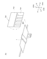
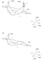
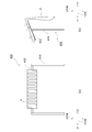
- the sandwiching device 700 is a device that sandwiches the workpiece T that has been carried while being placed on the placement plate 402 of the placement device 400 and receives the workpiece T from the placement device 400.
- the clamping device 700 is roughly composed of an upper clamping plate 702, a lower clamping plate 704, an upper clamping plate rotation shaft 706, a lower clamping plate rotation shaft 708, An upper bearing 710, a lower bearing 712, a clamping plate rotating motor 714, and a driving force transmission means 716 are provided.
- the upper clamping plate 702 is a rectangular plate material and is arranged so that the longitudinal direction is the width direction (arrow X direction).
- An upper clamping plate rotation shaft 706 is attached to the lower edge of the upper clamping plate 702.
- the upper clamping plate rotation shaft 706 is arranged so that the rotation axis thereof is in the width direction (arrow X direction).
- a pair of upper bearings 710 are provided at both ends of the upper clamping plate rotation shaft 706. These upper bearings 710 are attached to the inside of the front surface 106 ⁇ / b> A of the processing apparatus 1 where the door body 210 is provided.
- the lower holding plate 704 is a rectangular plate material having a larger area than the upper holding plate 702 described above. Further, the lower clamping plate 704 is arranged so that the longitudinal direction is the width direction (arrow X direction). Further, the lower clamping plate 704 is disposed directly below the upper clamping plate 702. A lower clamping plate rotation shaft 708 is attached to the upper edge of the lower clamping plate 704. The lower clamping plate rotation shaft 708 is arranged so that its rotation axis is in the width direction (arrow X direction). A pair of lower bearings 712 are attached to both ends of the lower clamping plate rotation shaft 708. These lower bearings 712 are attached to the front face 106A.
- the lower clamping plate rotation shaft 708 is disposed so that the rotation axis is in the width direction (arrow X direction) and parallel to the upper clamping plate rotation shaft 706.
- the lower holding plate 704 is formed with a plurality of linear slits 730 extending from one long side to which the lower holding plate rotating shaft 708 is attached to the other long side edge.
- the widths of the slits 730 are formed to be slightly wider than the width of the support member 808 of the transport device 800, and the support member 808 can be inserted into the slit 730 as described later.
- the clamping plate rotation motor 714 is a motor that can rotate forward and backward, and generates a driving force that rotates the upper clamping plate 702 and the lower clamping plate 704. Similarly to the bearings 710 and 712, the clamping plate rotating motor 714 is also attached to the inside of the front face 106A.
- the driving force transmission means 716 has a driving pulley 718, a driven pulley 720, a belt 722, and an interlocking means 724.
- the driving pulley 718 is attached to the output shaft end of the clamping plate rotating motor 714.
- the driven pulley 720 is attached to an end of the lower clamping plate rotation shaft 708 that is closer to the clamping plate rotation motor 714.
- the belt 722 is stretched between the driving pulley 718 and the driven pulley 720.
- the interlocking means 724 includes a first gear 726 attached to the upper clamping plate rotation shaft 706 and a second gear 728 attached to the lower clamping plate rotation shaft 708.
- the driving force of the clamping plate rotating motor 714 is transmitted to the lower clamping plate rotating shaft 708 via the driving pulley 718, the belt 722, and the driven pulley 720.
- the lower clamping plate rotation shaft 708 to which the driving force is transmitted rotates in a predetermined direction.
- the driving force transmitted to the lower clamping plate rotation shaft 708 is also transmitted to the upper clamping plate rotation shaft 706 via the interlocking means 724. Since the gears 726 and 728 are used as the interlocking means 724, the rotation direction of the upper clamping plate rotation shaft 706 and the rotation direction of the lower clamping plate rotation shaft 708 are opposite to each other.
- the upper clamping plate rotation shaft 706 rotates clockwise
- the lower clamping plate rotation shaft 708 rotates counterclockwise.
- the upper clamping plate 702 and the lower clamping plate 704 can be brought close to and away from each other, and the clamping device 700 can perform a clamping / opening operation.
- the transport apparatus 800 receives the processed object T from the clamping apparatus 700 and transports it.
- the transfer device 800 is disposed on the downstream side of the workpiece processing apparatus including at least one of the receiving transfer device 200 to the clamping device 700, and the workpiece processing apparatus and the transfer device 800 are disposed.
- a workpiece processing system is configured.
- the transfer device 800 generally includes a support 802, a support rotation mechanism (rotation mechanism) 804, and a support vertical movement mechanism 806.
- FIG. 9 shows a state in which the lower clamping plate 704 of the clamping device 700 is removed for convenience.
- the support tool 802 supports the workpiece T received from the clamping device 700.
- the support 802 has a plurality (four in this embodiment) of support members 808 and a support tool shaft 810. One end of each support member 808 is attached to the side periphery of the support tool shaft 810 so that the support members 808 are separated from each other and arranged in a line. Each support member 808 is attached in a direction orthogonal to the longitudinal direction of the support tool shaft 810. Thereby, the comb-shaped support 802 is formed.
- Each support member 808 includes a receiving portion 832 and a bent portion 834 as shown in FIG. 9B.
- the receiving portion 832 is a linear portion having one end attached to the support shaft 810.
- the bent portion 834 is an arc-shaped portion that extends obliquely upward from the other end of the receiving portion 832 (not limited to the arc shape, but may be any shape that extends obliquely upward).
- the support rotation mechanism 804 has a frame 812 and a rotation motor 814.
- the frame 812 is attached to the inside of the front surface 106A (the wall surface in the arrow Y2 direction) of the processing apparatus 1 where the door main body 210 is provided, and below the lower clamping plate rotation shaft 708 of the clamping apparatus 700.
- the frame 812 is a long member extending in the width direction (arrow X direction), and holds the support shaft 810 in a rotatable manner.
- Rotating motor 814 is a motor that can rotate forward and backward, and generates a driving force that rotates support shaft 810.
- the rotation motor 814 is fixed to the right end (direction of arrow X1) of the frame 812.
- the output shaft of the rotation motor 814 is connected to the right (arrow X1 direction) end of the support shaft 810. Accordingly, the support shaft 810 can be rotated by the driving force of the rotation motor 814.
- the support member shaft 810 allows the support member 808 to be in a desired position, such as a position that hangs downward or a position that is substantially horizontal.
- the support tool vertical movement mechanism 806 is a mechanism for moving the support tool rotation mechanism 804 and the support tool 802 up and down.
- This support vertical movement mechanism 806 generally has a pair of ball screws 816, a pair of nuts 817, a vertical movement motor 818, and a driving force transmission means 820.
- the pair of ball screws 816 are attached to the inside of the front surface 106A. Also, these ball screws 816 are arranged in the vertical direction (arrow Z direction) with an interval slightly narrower than the horizontal length of the frame 812. Each ball screw 816 is screwed with a nut 817. Each of the nuts 817 is attached to the end of the frame 812.
- the vertical movement motor 818 is a motor capable of normal rotation and reverse rotation, and generates a driving force for moving the support rotating mechanism 804 and the support 802 up and down.
- the vertical movement motor 818 is attached to the inside of the front face 106A. Further, the mounting height of the vertical movement motor 818 is set in the vicinity of the lowermost end to which the support 802 can move.
- the driving force transmission means 820 transmits the driving force from the vertical movement motor 818 to the pair of ball screws 816.
- the driving force transmission means 820 includes a driving pulley 822, a driven pulley 824, a pair of interlocking pulleys 826, a driving belt 828, and an interlocking belt 830.
- the drive pulley 822 is attached to the output shaft end of the vertical movement motor 818.
- the driven pulley 824 is attached to the lower end of the ball screw 816 close to the vertical movement motor 818.
- the pair of interlocking pulleys 826 are attached to the upper ends of the pair of ball screws 816, respectively.
- the driving belt 828 is bridged between the driving pulley 822 and the driven pulley 824.
- the interlocking belt 830 is bridged between a pair of interlocking pulleys 826.
- the driving force of the vertical movement motor 818 is transmitted to the ball screw 816 close to the vertical movement motor 818 via the driving pulley 822 and the driving belt 828.
- the ball screw 816 to which the driving force is transmitted rotates in a predetermined direction.
- This rotational force is transmitted to another ball screw 816 via a pair of interlocking pulleys 826 and an interlocking belt 830.
- the pair of ball screws 816 receive the driving force of the vertical movement motor 818 and rotate in the same direction at the same rotational speed.
- the pair of nuts 817 move up and down at the same speed, so that the frame 812 moves up and down while maintaining a horizontal state.
- the support 802 and the support rotation mechanism 804 also move up and down.
- the control device 900 supervises control of each unit in the processing device 1.
- the control device 900 mainly includes a ROM, a CPU, a RAM, and an input / output interface.
- the ROM stores an operating system, a control program for controlling each part of the processing device 1, and data necessary for executing the control program.
- the CPU is provided to load a control program stored in the ROM into the RAM or to execute it directly from the ROM. That is, the CPU can control the processing device 1 by executing the control program.
- the data processed by the CPU is transmitted to each part of the processing apparatus 1 (the receiving and conveying apparatus 200, the holding apparatuses 300A, 300B, etc.) via the input / output interface, and the data necessary for the processing of the CPU is processed by the processing apparatus. 1 from each unit (such as the imaging apparatus 500) via the input / output interface.
- control device 900 is roughly configured to receive and transport device control unit 902, holding device control unit 904, placement device control unit 906, imaging device control unit 908, and clamping device control unit.
- 910, transport device control unit 912, type recognition unit 914, length detection unit 915, sagging length detection unit 916, first point detection unit 920, first endpoint detection unit 922, second endpoint detection unit 924, third endpoint A detection unit 926, a fourth end point detection unit 928, a fifth end point detection unit 930, a sixth end point detection unit 932, a seventh end point detection unit 934, and an eighth end point detection unit 936 are provided.
- the receiving and conveying apparatus control unit 902 controls the operation of the receiving and conveying apparatus 200. That is, the receiving and conveying apparatus control unit 902 controls the operation of the door 202 and the conveying conveyor 204.
- the door main body 210 is opened and closed by the receiving and conveying apparatus control unit 902 controlling the operation of the door 202.
- the user can input the object to be processed T into the processing apparatus 1 and can extract the processed object T from the processing apparatus 1.
- the receiving and conveying apparatus control unit 902 controls the operation of the conveying conveyor 204, whereby the conveying conveyor 204 can be rotated in the forward direction or the reverse direction.
- the holding device control unit 904 controls operations of the holding mechanisms 310A and 310B and the moving mechanisms 320A and 320B in the holding devices 300A and 300B.
- the holding device control unit 904 controls the operation of the linear actuators 324A and 324B in the holding mechanisms 310A and 310B, thereby bringing the pair of finger members 322A and 322B close to or away from each other, and holding attached to the finger members 322A and 322B.
- the members 328A and 328B hold the workpiece T or release it.
- the holding device control unit 904 controls the operation of the rotary actuators 326A and 326B in the holding mechanisms 310A and 310B, so that the linear actuators 324A and 324B rotate through the connecting plate members 330A and 330B. Rotate around.
- the holding device control unit 904 controls the operation of the width direction moving mechanisms 332A and 332B in the moving mechanisms 320A and 320B, so that the holding mechanisms 310A and 310B move in the width direction (arrow X direction).
- the holding mechanism control unit 904 controls the operation of the vertical movement mechanisms 334A and 334B in the movement mechanisms 320A and 320B, so that the holding mechanisms 310A and 310B move in the vertical direction (arrow Z direction).
- the holding mechanism control unit 904 controls the operation of the front-rear direction moving mechanisms 336A, 336B in the moving mechanisms 320A, 320B, so that the holding mechanisms 310A, 310B move in the front-rear direction (arrow Y direction).
- the placement device control unit 906 controls the operations of the rotation mechanism 406 and the longitudinal movement mechanism 408 in the placement device 400.
- the placement device control unit 906 controls the operation of the rotation mechanism 406, whereby the placement plate 402 rotates and maintains a predetermined angle.
- the placement device control unit 906 controls the operation of the front-rear direction moving mechanism 408, whereby the placement plate 402 moves in the front-rear direction (arrow Y direction).
- the imaging device control unit 908 controls operations of the first imaging unit 502 and the second imaging unit 504 in the imaging device 500. By controlling the first imaging unit 502 and the second imaging unit 504, a digital image can be acquired at a desired timing.
- the clamping device control unit 910 controls the operation of the clamping plate rotating motor 714 in the clamping device 700.
- the clamping device controller 910 rotates the clamping plate rotating motor 714 in the forward direction, the upper clamping plate 702 and the lower clamping plate 704 are rotated in a direction close to each other (that is, the clamping device 700 is closed).
- the clamping plate rotating motor 714 rotates the clamping plate rotating motor 714 in the reverse direction, the upper clamping plate 702 and the lower clamping plate 704 are rotated in a direction away from each other (that is, the clamping device 700 is opened). Thereby, the opening / closing state of the clamping apparatus 700 can be controlled.
- the transport device control unit 912 controls operations of the support tool rotation mechanism 804 and the support tool vertical movement mechanism 806 in the transport device 800.
- the conveyance device control unit 912 controls the support member rotation mechanism 804 of the conveyance device 800, whereby the rotation angle of the support device 802 changes or maintains a predetermined angle.
- the transport device control unit 912 controls the support tool vertical movement mechanism 806 of the transport device 800, so that the support tool 802 moves in the vertical direction (arrow Z direction).
- the type recognition unit 914 recognizes the type of the workpiece T based on the image data obtained by the first imaging unit 502 and the second imaging unit 504 in the imaging apparatus 500.
- the type recognizing unit 914 previously stores image data (learning image data) of a wide variety of workpieces T such as T-shirts, running shirts, skirts, towels, handkerchiefs, films, papers, or sheets.
- image data learning image data
- Randmaiz forest is a machine learning algorithm that forms a forest using a plurality of decision trees and performs identification and the like.
- the “feature amount” here is not limited to the outer shape of the object to be processed T (for example, the presence or absence of a “collar”), but includes all elements on the appearance of the object to be processed T.
- the character pattern printed on the T-shirt is also an element for calculating the “feature amount”.
- the learning image data can be added by the user via a tablet PC having a camera function, a digital camera having a data transmission function, or the like.
- a person using “pixel value”, “HoG (Histogram oriented Gradients) feature”, or “Haar-like feature” is used. It is conceivable to apply the existing technology used for recognizing a person's face.
- the type recognizing unit 914 calculates the feature amount of the workpiece T currently being processed, which is copied to the image data obtained by the first imaging unit 502 and the second imaging unit 504, using the above-described method. . Then, the type recognizing unit 914 uses the Randmaiz forest discriminator for each calculated feature amount, and calculates the probability corresponding to a certain type (for example, T-shirt, running shirt, skirt, towel, etc.) for each type. Calculate as a percentage. Thereafter, the one with the highest probability (ie, the percentage) is recognized as the type of the workpiece T.
- a certain type for example, T-shirt, running shirt, skirt, towel, etc.
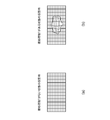
- the folding method is predetermined for each type of the workpiece T, and each type of folding method is stored as “folding information”.
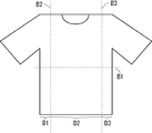
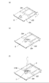
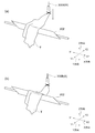
- folding information information about the position at which a certain type of workpiece T is folded is described. For example, when the workpiece T is a T-shirt and the T-shirt is folded in two in the length direction and is folded in three in the width direction, as shown in FIG. “Position information of horizontal fold line B1” necessary for folding in the length direction and “position information of first fold line B2” and “second fold line B3” required for folding in the width direction.
- Position information ”.
- the “lateral fold line B1” may be determined by a ratio to the length of the entire length, such as “position of half the length of the entire length”, instead of the specific “position information”. Good. Further, in the T-shirt, the end side from the first fold line B2 is referred to as a first end portion D1, and conversely, the end side from the second fold line B3 is referred to as a second end portion D3, and the first end portion D1. And the second end portion D3 is referred to as a central portion D2.
- the length detection unit 915 Based on the image data obtained by the first imaging unit 502 and the second imaging unit 504 in the imaging apparatus 500, the length detection unit 915 determines the length in the vertical direction of the workpiece T (the workpiece T is If it is a T-shirt, the length dimension of the T-shirt) and the length in the lateral direction (if the workpiece T is a T-shirt, the width dimension of the T-shirt) are obtained.
- ⁇ Drip length detection unit 916 The sagging length detection unit 916 sags from the edge line (first edge line) of the mounting plate 402 based on the image data obtained by the first imaging unit 502 and the second imaging unit 504 in the imaging apparatus 500. The lower end of the lowered workpiece T is detected, and the sagging length from the first edge line to the lower end is obtained.
- the first point detection unit 920 detects the first point P at the highest position of the workpiece T placed on the upper surface of the transport conveyor 204 in the receiving transport device 200. Specifically, the first point detection unit 920 is based on the image data from the first imaging unit 502 and the second imaging unit 504, or just above or near the obstacle member 222 in the receiving and conveying apparatus 200. Then, a part of the object T to be processed having a height higher than a predetermined level from the upper surface of the transfer conveyor 204 (for example, the highest portion from the upper surface of the transfer conveyor 204 when there are a plurality of objects) is detected as the first point P (FIG. 17 ( f)).
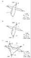
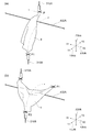
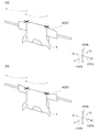
- the first end point detection unit 922 detects the first end point P1 farthest from the first point P in the workpiece T held by the holding mechanism 310A at the first point P. Specifically, the first end point detection unit 922 uses the first imaging unit 502 as the lowest point (the point at the lowest position) of the workpiece T that is held and lifted by the holding mechanism 310A at the first point P. And it detects based on the image data from the 2nd imaging part 504, and makes the said lowest point the 1st end point P1 (refer FIG.18 (h)).
- the second end point detection unit 924 detects the second end point P2 farthest from the straight line L1 connecting the first point P and the first end point P1. Specifically, the second end point detection unit 924 sets the lowest point in the workpiece T in a state where the holding mechanisms 310A and 310B hold both the first point P and the first end point P1 at the same height. Detection is performed based on image data from the first imaging unit 502 and the second imaging unit 504, and the lowest point is set as a second end point P2 (see FIG. 18 (i)).
- the third end point detection unit 926 detects a third end point P3 that is a corner of the workpiece T. Specifically, the third end point detection unit 926 converts the lower corner of the object T to be processed from the first imaging unit 502 and the second imaging unit 504 in a state where the third endpoint detection unit 926 is hung from the mounting plate 402. Based on this detection, the corner is set as the third end point P3 (see FIG. 19L).
- the fourth end point detection unit 928 detects the corner of the workpiece T facing the third end point P3 as the fourth end point P4. Specifically, the fourth end point detection unit 928 uses the image data from the first imaging unit 502 and the second imaging unit 504 as the corners facing the corners of the workpiece T corresponding to the third end point P3. And the corner is set as the fourth end point P4 (see FIG. 19L).
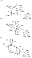
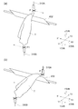
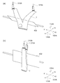
- the fifth end point detection unit 930 detects one end of the horizontal fold line B1 when the workpiece T is folded in the direction orthogonal to the longitudinal direction (lateral direction) as the fifth end point P5. Specifically, the fifth end point detection unit 930 has a lateral fold line B1 of the workpiece T on the upper edge line (first edge line C1) of the mounting plate 402 in a state where a predetermined angle is given from the horizontal state. In the state where the object to be processed T is hung down on the mounting plate 402 so as to follow, the upper corner of the object to be processed T is based on the image data from the first imaging unit 502 and the second imaging unit 504. The corner is detected as the fifth end point P5 (see FIG. 21 (p)).
- the sixth end point detection unit 932 detects the other end of the horizontal fold line B1 when the workpiece T is folded in the direction orthogonal to the longitudinal direction (lateral direction) as the sixth end point P6. Specifically, when the fifth end point detection unit 930 detects the fifth end point P5, the sixth end point detection unit 932 sets the corner facing the corner of the workpiece T corresponding to the fifth end point P5 to the first end. Detection is performed based on image data from the first imaging unit 502 and the second imaging unit 504, and the corner is set as a sixth end point P6 (see FIG. 21 (p)).
- the seventh end point detection unit 934 detects one end of the first fold line B2 when the workpiece T is folded in the longitudinal direction (vertical direction) as the seventh end point P7. Specifically, the seventh end point detection unit 934 sets the first fold line of the workpiece T to the upper edge line (first edge line C1) of the mounting plate 402 in a state where a predetermined angle is given from the horizontal state. Based on the image data from the first imaging unit 502 and the second imaging unit 504, the upper corner of the workpiece T is hung on the mounting plate 402 so as to be along B2. And the corner is set as the seventh end point P7 (see FIG. 22 (s)).
- the eighth end point detection unit 936 detects the other end of the first fold line B2 when the workpiece T is folded in the longitudinal direction (longitudinal direction) as the eighth end point P8. Specifically, when the seventh end point detection unit 934 detects the seventh end point P7, the eighth end point detection unit 936 sets the corner opposite the corner of the workpiece T corresponding to the seventh end point P7 to the first end. Detection is performed based on image data from the first imaging unit 502 and the second imaging unit 504, and the corner is set as an eighth end point P8 (see FIG. 22 (s)).
- the receiving and conveying apparatus control unit 902 accepts the object T to be processed in a messy state in the processing apparatus 1, and then makes the object T easy to lift by the holding apparatus 300A.
- the operations of the door 202 and the transfer conveyor 204 are controlled so as to perform the first control to the fifth control.
- the receiving / conveying device control unit 902 controls the door opening / closing motor 216 so that the door body 210 is opened (first control).
- the receiving and conveying apparatus control unit 902 controls the conveyor driving motor 244 so that the conveying conveyor 204 rotates in the forward direction (second control).
- the receiving and conveying apparatus control unit 902 controls the door opening / closing motor 216 so that the door main body 210 is closed (third state). control).
- the front-rear direction moving mechanism 408 in the placement device 400 is positioned in advance so that the workpiece sensor 409 is positioned at the position of the obstacle member 222 when the door body 210 is closed.
- the receiving and conveying device control unit 902 controls the conveyor drive motor 244 so that the conveying conveyor 204 rotates in the reverse direction (fourth control).
- the receiving and conveying apparatus control unit 902 recognizes that the workpiece T has climbed on the obstacle member 222, that is, the control apparatus 900 receives an obstacle from the workpiece sensor 409.
- the conveyor drive motor 244 is controlled so that the transport conveyor 204 stops (fifth control).
- the holding device control unit 904 and the placement device control unit 906 lift the workpiece T on the transport conveyor 204, identify the workpiece T, and further fold the workpiece T in the following manner.
- the sixth control to the twenty-first control are performed.
- the holding device control unit 904 controls the holding device 300A so that the workpiece T is lifted after the one holding mechanism 310A holds the workpiece T on the transport conveyor 204 at the first point P (sixth). Control).
- the holding device control unit 904 controls the holding device 300B after the sixth control so that the other holding mechanism 310B holds the first end point of the workpiece T (seventh control).
- the holding device control unit 904 moves horizontally while holding the first point P while the one holding mechanism 310A holds the first point P, and the other holding mechanism 310B has the first end point.
- the holding device 300B is controlled to lift P1 to the same height as the first point P (eighth control).
- the holding device control unit 904 controls the holding device 300B so that the other holding mechanism 310B opens the first end point P1, and then holds the second end point P2 (9th). Control).
- the holding device control unit 904 and the mounting device control unit 906 lift the second end point P2 to the same height as the first point P while the other holding mechanism 310B lifts the mounting plate 402 in the forward direction.
- the holding device 300B and the mounting device 400 are controlled to rotate (tenth control).
- the holding device control unit 904 causes the one holding mechanism 310A and the other holding mechanism 310B to set the horizontal fold line B1 of the workpiece T to the upper edge line (first edge) of the mounting plate 402.
- the workpiece T is placed on the mounting plate 402 along the line C1), after which one holding mechanism 310A releases the first point P and the other holding mechanism 310B releases the second end point P2.
- the holding devices 300A and 300B are controlled (11th control).
- the holding device control unit 904 controls the holding device 300A so that one holding mechanism 310A holds the third end point P3 (a twelfth control).
- the holding device control unit 904 controls the holding device 300A so that one holding mechanism 310A moves the third end point P3 directly above the fourth end point P4 (13th control).
- the holding device control unit 904 controls the holding device 300B so that the other holding mechanism 310B holds the fourth end point P4 (fourteenth control).
- the holding device control unit 904 and the mounting device control unit 906 are configured such that the other holding mechanism 310B has the fourth end point P4 on the right side of the third end point P3 (arrow X1 direction) and the third After lifting up to the same height as the end point, the mounting plate 402 is rotated in the forward direction (the rotating shaft 412 rotates counterclockwise when viewed from the left side surface 102D) to reverse the front and back of the workpiece T.
- the holding device 300 ⁇ / b> B is configured so that the horizontal fold line B ⁇ b> 1 of the workpiece T is set along the upper edge line (first edge line C ⁇ b> 1) of the mounting plate 402 and the workpiece T is hung on the mounting plate 402. And the mounting apparatus 400 is controlled (15th control).
- the holding device control unit 904 and the mounting device control unit 906 hold the mounting plate 402 vertically, one holding mechanism 310A holds the fifth end point, and the other holding mechanism 310B. Controls the holding devices 300A and 300B and the mounting device 400 so as to hold the sixth end point (sixteenth control).
- the holding device control unit 904 and the placement device control unit 906 hold the workpiece T while holding the fifth end point P5 and the sixth end point P6 by both the holding mechanisms 310A and 310B.
- the mounting plate 402 is held horizontally.
- the fifth end point P5 and the sixth end point P6 are arranged in the front-rear direction outside the placement plate 402 by the one holding mechanism 310A and the other holding mechanism 310B.
- the holding devices 300A and 300B and the mounting device 400 are controlled so that the one holding mechanism 310A and the other holding mechanism 310B place the lower end portion of the object to be processed T on the upper surface of the mounting plate 402 (17th embodiment). Control).
- the holding device control unit 904 causes the one holding mechanism 310A and the other holding mechanism 310B to open the fifth end point P5 and the sixth end point P6 (18th control).
- the mounting device control unit 906 mounts the mounting plate 402 so that the mounting plate 402 rotates in the reverse direction (the rotation shaft 412 rotates clockwise as viewed from the left side surface 102D) and becomes vertical.
- the holding device control unit 904 and the mounting device control unit 906 hold the seventh end point P7 with one holding mechanism 310A and hold the eighth end point P8 with the other holding mechanism 310B.
- the holding devices 300A and 300B and the mounting device 400 are controlled so that the mounting plate 402 is horizontal (20th control).
- the holding device control unit 904 places the workpiece T on the horizontal placement plate 402 while holding the seventh end point P7 and the eighth end point P8 with both holding mechanisms 310A and 310B.
- the holding devices 300A and 300B are controlled (21st control).
- the placement device control unit 906 and the holding device control unit 910 fold the workpiece T and hold the folded workpiece T in a folded state from the twenty-second control to the twenty-third control described below. Control.
- the placing device control unit 906 and the sandwiching device control unit 910 bring the placing plate 402 on which the treatment object T is placed closer to the sandwiching device 700 while approaching the workpiece T to be processed.
- the mounting device 400 and the clamping device 700 are controlled so as to be clamped by the upper clamping plate 702 and the lower clamping plate 704 together with the mounting plate 402 (22nd control).
- the mounting device control unit 906 controls the mounting device 400 so that the mounting plate 402 is separated from the clamping device 700 (23rd control).
- the clamping device control unit 910 and the conveyance device control unit 912 prevent the collapse of the folded workpiece T from being stored in the workpiece receiving member 220 while preventing the collapse of the workpiece T from the 24th control described below. 26 is controlled.
- the holding device control unit 910 and the conveyance device control unit 912 raise the support tool 802 to the upper limit and rotate the support tool shaft 810 until the support member 808 is in a horizontal state. Thereafter, the conveying device 800 and the clamping device 700 are controlled so as to release the workpiece T (24th control).
- the transfer device control unit 912 controls the transfer device 800 so that the support 802 is lowered while maintaining the horizontal state of the support member 808 (25th control).
- the clamping device control unit 910 and the conveyance device control unit 912 stop the lowering of the support 802 after the 25th control, and then control the conveyance device 800 so that the support member 808 rotates vertically downward. (26th control).
- FIG. 16A when the processing operation of the T-shirt T by the processing device 1 is started, the door body 210 is opened (first control, step S1). Then, as shown in FIG. 16B, the transport conveyor 204 rotates in the forward direction (the direction in which the T-shirt T is separated from the door body 210) (second control, step S2). In this state, the laundered and dried T-shirt T is put into the processing apparatus 1.
- the door main body 210 When the door main body 210 is open, the door main body 210 rotates about the door shaft 212 as shown in FIG. Similarly, the workpiece receiving member 220 and the obstacle member 222 attached to the door main body 210 are also rotated about the door shaft 212. That is, the workpiece receiving member 220 and the obstacle member 222 are in a state of being separated from the upper surface of the transport conveyor 204.
- the inserted T-shirt T is transported by the transport conveyor 204 rotating in the forward direction (the direction in which the T-shirt T is separated from the door main body 210), and the obstacle member 222 is disposed when the door main body 210 is closed.
- the door main body 210 is closed as shown in FIG. 16C (third control, Step S3). Note that the fact that the T-shirt T has been transported to the far side from the position where the obstacle member 222 is disposed uses the workpiece sensor 409 attached to the moving plate 416R of the front-rear direction moving mechanism 408 in the transporting device 400. Is confirmed.
- the volume of the workpiece T can be estimated by adjusting the front and rear position of the workpiece sensor 409. Can do. Further, instead of this, it may be determined that the T-shirt has been transported to the far side when the transport conveyor 204 has continued to rotate in the forward direction for a predetermined time (control by a timer). When the door main body 210 is closed, the obstruction member 222 is disposed immediately above the transport conveyor 204 (near the surface).
- the transfer conveyor 204 rotates in the reverse direction (the direction in which the T-shirt T approaches the door body 210) (fourth control, step S4). Thereby, the T-shirt T moves toward the concave surface of the obstacle member 222. Then, the T-shirt T that is moved by the transfer conveyor 204 rides on the obstacle member 222 (the fact that the T-shirt T rides on the obstacle member 222 is, for example, a workpiece sensor arranged above the obstacle member 222. 409 or the image pickup apparatus 500.) When the T-shirt T rides on the obstacle member 222, the first point detection unit 920 detects a part of the T-shirt T immediately above the obstacle member 222 as the first point P (first point detection step, step S5).
- the transfer conveyor 204 stops as shown in FIG. 17E (fifth control, step S6).
- the transport conveyor 204 may be stopped immediately upon detecting that the T-shirt T has exceeded the top of the obstacle member 222. In this way, the T-shirt T tends to extend obliquely upward from the top of the obstruction member 222, so that the holding mechanisms 310A and 310B are the first in the holding mechanisms 310A and 310B as compared to after the T-shirt T has completely overcome the obstruction member. It becomes easier to hold the point P.
- one holding mechanism 310A holds the detected first point P. More specifically, the pair of finger members 322A come close to each other when the linear actuator 324 provided in one holding mechanism 310A moves (at this time, the finger member 322A is held substantially horizontally by the rotary actuator 326A. ing.). When the pair of finger members 322A come close to each other, the gripping members 328A attached to the distal ends of the finger members 322A come close to each other and hold (hold) the first point P of the T-shirt T. After one holding mechanism 310A holds the first point P, the holding mechanism 310A lifts the T-shirt T until the first point P reaches a position higher than the mounting plate 402 slightly inclined from the horizontal state.
- the state shown in FIG. 18G is obtained (sixth control, step S7).
- the reason why the mounting plate 402 is slightly inclined from the horizontal state is to prevent the T-shirt T from sliding down.
- the inclination of the mounting plate 402 is preferably, for example, 0 to 80 degrees with respect to the vertical direction.
- the holding mechanism (310A, 310B) and the mounting plate 402 In order not to interfere, 30 to 80 degrees with respect to the vertical direction is more preferable.
- the finger member 322A is vertically lowered by the rotary actuator 326A.
- the transfer conveyor 204 rotates again in the forward direction, and the remaining objects to be processed are processed.
- the object T is conveyed in the forward direction.
- the process returns to step S4 to lift the workpiece T to be folded next, the transport conveyor 204 rotates in the reverse direction, and the workpiece T becomes an obstacle member. It moves toward the concave surface of 222.
- ⁇ Recognition process (FIG. 13)> Next, the recognition process will be described. At this stage, the control device 900 has not identified that the workpiece is a T-shirt.
- a type identification step (FIG. 13: step S14-2), which will be described later, the type of the object to be processed is identified based on the feature quantity that the type recognition unit 914 can visually grasp from the T-shirt T (T-shirt T is, for example, "T-shirt” instead of "trousers"""towels""skirt”).
- the suspended T-shirt T (FIG. 19G) is developed. It is necessary to (expand).
- the object to be processed is the T-shirt T only when both ends of the cuffs of the T-shirt T are expanded to the state held by the holding mechanisms 310A and 310B. It has come to be. This unfolding operation will be described with reference to FIGS. 18 (h) to 19 (j).
- the imaging device 500 acquires image data of the T-shirt T suspended at the first point P, and sends the image data to the control device 900.
- the first endpoint detection unit 922 Based on the image data sent to the control device 900, the first endpoint detection unit 922 detects the first endpoint P1 (first endpoint detection step, step S8). More specifically, the first end point detection unit 922 detects the lowest point (the point at the lowest position) in the T-shirt T suspended at the first point P, and uses this lowest point as the first end point. Let P1.
- the length (length) of the T-shirt T is long, the position of the lowest point may be too low and the lowest point may not enter the image data.
- the holding device control unit 904 moves the one holding mechanism 310A holding the first point P closer to the door 202. Move horizontally in the direction of arrow Y2.
- one holding mechanism 310A is moved in this way, the length of the T-shirt T hanging from the mounting plate 402 is shortened. Thereby, even when the length (length) of the T-shirt T is long, the lowest point of the T-shirt T can be included in the image data.
- the other holding mechanism 310B holds the detected first end point P1 (seventh control, step S9).
- the finger member 322B of the other holding mechanism 310B is held vertically upward by the rotary actuator B.
- one holding mechanism 310A horizontally moves in the right direction (arrow X1 direction) while holding the first point P, and the other holding mechanism 310B moves the first end point P1 to the same height as the first point P.
- the finger member 322B is vertically downward by the rotary actuator 326B while the other holding mechanism 310B is lifting the first end point P1.
- the imaging apparatus 500 acquires image data of the T-shirt T in which the first end point P1 and the first point P are lifted at the same height, and the image data Is sent to the control device 900.
- the second endpoint detection unit 924 Based on the image data sent to the control device 900, the second endpoint detection unit 924 detects the second endpoint P2 (second endpoint detection step, step S11). More specifically, the second end point detection unit 924 has the lowest point in the workpiece T in which the holding mechanisms 310A and 310B hold both the first point P and the first end point P1 at the same height. Is the second end point P2. That is, the second end point P2 farthest from the straight line L1 connecting the first point P and the first end point P1 is detected.
- the holding device control unit 904 includes one holding mechanism 310A that holds the first point P, and the first end point P1. Is moved horizontally in the direction approaching the door 202 (arrow Y2 direction).
- the both holding mechanisms 310A and 310B are moved in this way, the length of the T-shirt T that hangs down from the mounting plate 402 is shortened. Thereby, even if the width of the T-shirt T is wide, the lowest point of the T-shirt T can be entered in the image data.
- the other holding mechanism 310B that has held the first end point P1 opens the first end point P1, and then, the second end point P2 is set. Hold (9th control, step S12). At this time, the finger member 322B of the other holding mechanism 310B is held vertically upward by the rotary actuator B.
- the other holding mechanism 310B holding the second end point P2 lifts the second end point P2 to the same height as the first point P.
- the finger member 322B is vertically downward by the rotary actuator 326B while the other holding mechanism 310B is lifting the first end point P1.
- the mounting plate 402 rotates in the forward direction (tenth control, step S13).
- the T-shirt T is suspended from the placement plate 402 on the back side (the direction of the arrow Y1, the imaging device 500 side) so that the length of the T-shirt T is in the vertical direction. That is, one holding mechanism 310A and the other holding mechanism 310B each hold the sleeve of the T-shirt T.
- the mounting board 402 does not interfere with length detection or the like of the image data of the imaging apparatus 500 of the T-shirt T. .
- the mounting plate 402 may move in a direction (arrow Y2 direction) approaching the door 202 while pushing the T-shirt T toward the imaging device 500 side.
- the length detection unit 915 measures the length in the vertical direction (length) and the length in the horizontal direction (width) of the T-shirt T based on the image data obtained from the imaging device 500, and the measurement.
- the result is temporarily stored in the RAM or the like of the control device 900 (length measurement step, step S14-1).
- the type recognition unit 914 recognizes the type of the T-shirt T based on the image data obtained from the imaging device 500 (type identification step, step S14-2). Specifically, the feature amount of the T-shirt T is calculated from the image data. This feature amount is applicable to all elements that can be visually recognized from the T-shirt T, such as the shape of the T-shirt T, the overall length, and the surface pattern and color. After calculating the feature amount of the T-shirt T, the type recognizing unit 914 recognizes the type of the workpiece T using a Randmaiz forest classifier created in advance for each feature amount. When the type recognition is completed, the type recognition unit 914 obtains “folding information” corresponding to the type (T-shirt in this embodiment).
- the first point P is the sleeve portion of the T-shirt T is described, so that the both ends of the cuffs of the T-shirt T are developed in the shortest time until they are held by the holding mechanisms 310A and 310B Has been.
- the first point P can be any part of the T-shirt T.
- both ends of the cuffs of the T-shirt T are not held by the holding mechanisms 310A and 310B when the second end point is held.
- the type recognition unit 914 recognizes that the T-shirt T is a “T-shirt”. Can not. Therefore, the processing apparatus 1 is in a state where both ends of the cuffs of the T-shirt T are held by the holding mechanisms 310A and 310B (the type recognition unit 914 recognizes that the T-shirt T is “T-shirt”). Further, the lowest point of the T-shirt T is changed by holding mechanisms 310A and 310B a plurality of times.
- the number of times of change required until the type recognition can be changed depending on the type of the workpiece T and the position of the workpiece T at the first first point P. As an example, if the workpiece T has long sleeves or hems such as long pants or long sleeves, the workpiece T is changed by approximately two times of change, and in the case of a T-shirt or towel, the change of the item T is changed by approximately three times. Can be recognized.
- FIG. 19 (k) Next, as shown in FIG. 19 (k), one holding mechanism 310A holding the first point P and the other holding mechanism 310B holding the second end point P2 are arranged in the door direction (arrows). Y2 direction). Thereafter, one holding mechanism 310A opens the first point P. The other holding mechanism 310B opens the second end point P2 (11th control, sagging length detection step, step S15). If it demonstrates concretely, the position of the horizontal fold line B1 of T-shirt T is contained in the information of T-shirt T acquired previously. In the case of the T-shirt T, the horizontal fold line B1 is set at a position that is exactly half the length.
- the holding mechanisms 310A and 310B are moved in the door direction (until the horizontal fold line B1 is aligned with the upper edge line (first edge line C1) of the mounting plate 402 at an angle from the horizontal. Move horizontally in the direction of arrow Y2.
- the T-shirt T moves so as to rub the first edge line C1 (moves so that the T-shirt T is pressed against the placing plate 402), so that the T-shirt T and the first edge line C1
- the wrinkles at the contact points can be removed.
- This also causes the hem side (lower part) of the T-shirt T to face the first imaging unit 502 attached to the inner surface of the back surface 106B of the processing apparatus 1.
- the sagging length detection unit 916 that has received the image data continuously captured by the first imaging unit 502 in the imaging apparatus 500 sequentially starts from the first edge line C1 of the mounting plate 402 to the lower end of the T-shirt T ( Check the length of sag. As described above, since the position of the horizontal fold line B1 of the T-shirt T is set at a position that is exactly half the length of the T-shirt T, the sagging length is half the length of the T-shirt T.
- the holding device control unit 904 stops the horizontal movement of both the holding mechanisms 310A and 310B based on the signal from the sag length detecting unit 916 that detects this.
- the imaging device 500 acquires image data of the T-shirt T suspended from the mounting plate 402 and sends the image data to the control device 900.
- the third endpoint detection unit 926 detects the third endpoint P3 (third endpoint detection step, step S16).
- the fourth endpoint detection unit 928 detects the fourth endpoint P4 (fourth endpoint detection step, step S17). In addition, you may implement this 4th endpoint detection process in the case of the 13th control mentioned later and step S19.
- the third end point detection step will be described in detail.
- the third end point detection unit 926 is based on the image data, and is below the right side (arrow X1 direction) on the hem side of the T-shirt T in a state of hanging from the placement plate 402. A corner is detected and the corner is defined as a third end point P3.
- the fourth end point detection step will be specifically described.
- the fourth end point detection unit 928 is based on the image data, and is on the left side (in the direction of the arrow X2) on the hem side of the T-shirt T in a state where it hangs down from the mounting plate 402. Is detected as a fourth end point P4.
- the one holding mechanism 310A holds the third end point P3 (a twelfth control, step S18). At this time, the finger member 322A of one holding mechanism 310A is held vertically upward by the rotary actuator 326A.
- the one holding mechanism 310A that holds the third end point P3 moves the third end point P3 directly above the fourth end point P4 (13th control, step). S19). Specifically, one holding mechanism 310A moves to the left (in the direction of the arrow X2) while holding the third end point P3. As a result, the third end point P3 moves right above the fourth end point P4. Note that the finger member 322A is vertically downward by the rotary actuator 326A while one holding mechanism 310A lifts the third end point P3.
- the other holding mechanism 310B holds the fourth end point P4 (14th control, step S20). Specifically, the rotary actuator 326B of the other holding mechanism 310B directs the finger member 322B upward. The other holding mechanism 310B holds the fourth end point P4 from below the T-shirt T with the finger member 322B facing upward.
- the other holding mechanism 310B has the fourth end point P4 on the right side of the third end point P3 (in the direction of the arrow X1) and the same height as the third end point P3. Lift it up.
- the other holding mechanism 310B operates the rotary actuator 326 to direct the finger member 322 downward.
- the mounting plate 402 rotates in the forward direction (the rotation shaft 412 is counterclockwise as viewed from the left side surface 102D). Thereby, the front and back of the T-shirt T are reversed.
- the back surface of the T-shirt T faces the first imaging unit 502, but the front of the T-shirt T is moved to the first imaging unit 502 by the operations so far. It comes to face.
- one holding mechanism 310A that holds the third end point P3 and the other holding mechanism 310B that holds the fourth end point P4 move horizontally in the door direction (the direction of the arrow Y2). .
- one holding mechanism 310A opens the third end point P3.
- the other holding mechanism 310B opens the fourth end point P4 (fifteenth control, sagging length detection step, step S21).
- step S15 both ends until the horizontal fold line B1 is aligned with the upper edge line (first edge line C1) of the mounting plate 402 at an angle from the horizontal.
- the holding mechanisms 310A and 310B move horizontally in the door direction (arrow Y2 direction).
- the collar side (upper part) of the T-shirt T faces the first imaging unit 502 attached to the inner surface of the back surface 106B of the processing apparatus 1.
- Whether or not the lateral fold line B1 is along the first edge line is determined by the sagging length detection unit 916 in the control device 900.
- the sagging length detection unit 916 that has received the image data continuously captured by the first imaging unit 502 in the imaging apparatus 500 sequentially starts from the first edge line of the mounting plate 402 to the lower end (collar) of the T-shirt T.
- the sagging length detection unit 916 that detects this stops the horizontal movement of both the holding mechanisms 310A and 310B.
- the imaging device 500 acquires image data of the T-shirt T suspended from the mounting plate 402 and sends the image data to the control device 900.
- the fifth endpoint detector 930 detects the fifth endpoint P5 (fifth endpoint detection step, step S22).
- the sixth endpoint detection unit 932 detects the sixth endpoint P6 (sixth endpoint detection step, step S23).
- the fifth end point detection unit 930 causes the horizontal fold line B1 to follow the upper edge line (first edge line C1) of the mounting plate 402 in a state where a predetermined angle is given from the horizontal state.
- the upper right corner (in the direction of the arrow X1) of the T-shirt T is based on image data from the first imaging unit 502 and the second imaging unit 504.
- the right upper corner is detected as the fifth end point P5.
- the sixth end point detection unit 932 detects the upper left corner (in the direction of the arrow X2) of the T-shirt T based on the image data from the first imaging unit 502 and the second imaging unit 504, and this upper left side.
- the corner is defined as a sixth end point P6.
- One holding mechanism 310A holds the fifth end point P5.
- the other holding mechanism 310B holds the sixth end point P6 (sixteenth control, step S24).
- one holding mechanism 310A operates the rotary actuator 326A to hold the fifth end point P5 with the finger member 322A facing downward.
- the other holding mechanism 310B operates the rotary actuator 326B to hold the sixth end point P6 with the finger member 322B facing downward.
- both the holding mechanisms 310A and 310B allow a part or all of the T-shirt T to be placed from the mounting plate 402 while holding the fifth end point P5 and the sixth end point P6. Also lift it high. Thereafter, the mounting plate 402 is rotated and held horizontally. After that, both holding mechanisms 310A and 310B move the fifth end point P5 and the sixth end point P6 to the right (arrow X1 direction) from the center of the mounting plate 402 in the width direction (arrow X direction), and the holding mechanism.
- both holding mechanisms 310A and 310B move so that the fifth end point P5 and the sixth end point P6 are aligned in the front-rear direction (arrow Y direction) to the right of the center of the mounting plate 402 in the width direction (X direction).
- the edge line (in the direction of arrow Y1) on the horizontal mounting plate 402 is referred to as a first edge line C1.
- the edge line on the door side (in the arrow Y2 direction) of the mounting plate 402 is referred to as a second edge line C2.
- a part of the T-shirt T is placed on the first plate 402 on the first side It is more preferable to move it along the edge line C1 because wrinkles of the T-shirt T can be suppressed.
- both holding mechanisms 310A, 310B The positions of the fifth end point P5 and the sixth end point P6 are determined so that the vertical plane includes the first fold line B2 of the T-shirt T. In the movement so far, both holding mechanisms 310A and 310B move so that the distance between the fifth end point P5 and the sixth end point P6 is always constant.
- both holding mechanisms 310A and 310B move downward while moving in the left direction (arrow X2 direction).
- the T-shirt T slides on the placement plate 402 along the left direction (arrow X2 direction), and the lower end (collar side) of the T-shirt T is placed on the horizontal upper surface of the placement plate 402. (17th control, step S25).
- the finger members 322A and 322B of both holding mechanisms 310A and 310B are held horizontally and horizontally by the rotary actuators 326A and 326B.
- the first fold line B2 of the T-shirt T includes the first edge line C1 of the placement plate 402.
- the T-shirt T can be positioned such that the first fold line B ⁇ b> 2 of the T-shirt T is the first of the mounting plate 402 when the T-shirt T is mounted on the upper surface of the mounting plate 402. Along the edge line C1. At this time, since the T-shirt T slides along the mounting plate 402 (moves while rubbing against the mounting plate 402), the wrinkles of the T-shirt T can be extended.
- one holding mechanism 310A opens the fifth end point P5.
- the other holding mechanism 310B opens the sixth end point P6 (18th control, step S26).
- the mounting plate 402 rotates in the reverse direction (the rotation shaft 412 rotates clockwise as viewed from the left side surface 102D) and becomes vertical (19th).
- the T-shirt T is hung on the mounting plate 402 with the first folding line B2 along the first edge line C1 of the mounting plate 402.
- the first end portion D1 of the T-shirt T hangs down on the back side (in the direction of the arrow Y1) of the mounting plate 402.
- the central portion D2 and the second end portion D3 of the T-shirt T hang down to the door side (arrow Y2 direction) of the mounting plate 402.
- the imaging device 500 acquires image data of the T-shirt T hung on the mounting plate 402, and sends the image data to the control device 900.
- the seventh endpoint detection unit 934 detects the seventh endpoint P7 (seventh endpoint detection step, step S28).
- the eighth endpoint detection unit 936 detects the eighth endpoint P8 (eight endpoint detection step, step S29). Specifically, the seventh end point detection unit 934 is hung so that the first fold line B2 of the workpiece T is along the upper edge line (first edge line C1) of the placing plate 402 in the vertical state.
- the upper right corner (in the direction of the arrow X1) of the T-shirt T is detected based on image data from the first imaging unit 502 and the second imaging unit 504, and the corner is set as a seventh end point P7.
- the eighth end point detection unit 936 detects the upper left corner (in the direction of the arrow X2) of the T-shirt T based on the image data from the first imaging unit 502 and the second imaging unit 504, and the corner Is an eighth end point P8.
- one holding mechanism 310A holds the seventh end point P7.
- the other holding mechanism 310B holds the eighth end point P8.
- one holding mechanism 310A operates the rotary actuator 326A to hold the seventh end point P7 with the finger member 322A facing downward.
- the other holding mechanism 310B operates the rotary actuator 326B to hold the eighth end point P8 with the finger member 322B facing downward.
- both holding mechanisms 310A, 310B are lifted until the T-shirt T is separated from the mounting plate 402 while holding the seventh end point P7 and the eighth end point P8. Then, the mounting plate 402 rotates in the forward direction and becomes horizontal (20th control, step S30).
- both holding mechanisms 310A and 310B place the T-shirt T on the horizontal placement plate 402 (21st control, step S31). Specifically, both holding mechanisms 310 ⁇ / b> A and 310 ⁇ / b> B move horizontally in the door direction (in the direction of arrow Y ⁇ b> 2) to position the T-shirt T closer to the door than the placement plate 402. Thereafter, the holding mechanisms 310A and 310B move the T-shirt T in the back direction (arrow Y1 direction) while lowering the T-shirt T. As a result, the T-shirt T is placed on the placing plate 402 so that the center portion D2 overlaps the first end portion D1.
- the fold line between the first end portion D1 and the central portion D2 coincides with the first fold line B2 of the T-shirt T. Further, as described above, since the length and width of the T-shirt T are measured by the length detection unit 915, both the holding mechanisms 310A and 310B are based on the positional relationship with the placement plate 402.
- the T-shirt T can be placed so that the second fold line B3 at T is along a second edge line C2 that is an edge line of the placement plate 402 in the door direction (arrow Y2 direction). At this time, the second edge line C ⁇ b> 2 hangs down from the mounting plate 402.
- the placing plate 402 on which the T-shirt T is placed so that the second edge line C2 of the placing plate 402 is along the second fold line B3 is sandwiched. Move horizontally to the vicinity of the device 700.
- the upper clamping plate 702 and the lower clamping plate 704 rotate in a direction approaching each other. Specifically, the upper clamping plate 702 rotates from the vertically upward state to the horizontal state. The lower clamping plate 704 rotates from the vertically downward state to the horizontal state.
- the T-shirt T and the placing plate 402 are held by the upper holding plate 702 and the lower holding plate 704 that have been rotated (22nd control, step S32).
- the second end portion D3 that hangs down from the placement plate 402 in the T-shirt T is lifted by the lower clamping plate 704. As a result, the second end portion D3 is folded along the second fold line B3.
- a placing plate 402 is inserted between the center portion D2 (first end portion D1) and the second end portion D3 of the T-shirt T.
- the mounting plate 402 moves and moves away from the clamping device 700 (23rd control, step S33).
- the clamping apparatus 700 will be in the state which clamped only the T-shirt T.
- FIG. Further, the sandwiched T-shirt T has a length direction folded in two along a horizontal fold line B1, and further, a width direction folded in three along a first fold line B2 and a second fold line B3.
- the support member 808 fits into the slit 730 provided in the lower holding plate 704, the support member 808 and the lower holding plate 704 are mutually connected even when the transport device 800 is provided directly below the holding device 700. There is no interference. As a result, the folded T-shirt T released from the clamping device 700 can be placed on the support member 808 without losing its shape.
- the support 802 descends while maintaining the horizontal state of the support member 808 (25th control, step S35).
- the support tool 802 stops the lowering, and then the support member 808 is rotated vertically downward (26th Control, step S36).
- the T-shirt T sliding down from above the support member 808 is accommodated in the workpiece receiving box R without being deformed (see FIG. 24 (y)).
- the folded T-shirt T is stacked on the workpiece receiving box R by repeating the above-described steps S1 to S36.
- the holding devices 300A and 300B that hold the workpiece T, and the mounting plate 402 that is capable of mounting the workpiece T and is rotatably provided. are controlled in combination with each other (for example, 10th control and 15th control). For this reason, when the workpiece T is moved from one side (for example, door side) to the other side (for example, the back side) of the mounting plate 402, the entire workpiece T is lifted above the mounting plate 402. Or, it is not necessary to move the entire workpiece T greatly in the front-rear direction (arrow Y direction).
- the lower part of the workpiece T is still on the other side of the mounting plate 402.
- the lower part of the workpiece T remaining on the other side can be rolled up and moved to one side.
- the lowest point of the workpiece T is When the image data does not enter, the workpiece T is not lifted further, but the workpiece T is pulled horizontally to the opposite side via the mounting plate 402. Thereby, the position of the lowest point of the to-be-processed object T can be raised. In addition, if this is done, a space is not required to lift the workpiece T further, so that the height of the processing apparatus 1 can be made compact.
- the workpiece T is folded using the two edge lines (the first edge line C1 and the second edge line C2) of the mounting plate 402. Therefore, the workpiece T can be folded into two or three with a beautiful fold.
- the method of folding the workpiece T described above is not particularly limited, and it may be folded in four or in a unique position according to the shape of the workpiece T. .
- the processing apparatus 1 by providing the mounting plate 402, it is possible to work by placing the workpiece T on the mounting plate 402. Thereby, for example, when the other holding mechanism 310B that has held the first end point P1 next holds the second end point P2 (the ninth control), the second end point P1 is released while the second end point P1 is released. It can be moved to hold the end point P2. This is because one holding mechanism 310 ⁇ / b> A holds the first point P and the placing plate 402 supports the workpiece T during the movement.
- the configuration of the holding devices 300A and 300B is simplified.
- the work such as shaking of the workpiece T can be reduced by performing the work by placing the workpiece T on the mounting plate 402.
- the holding mechanism 310A is positioned at a position higher than the mounting plate 402 slightly inclined from the horizontal state.
- the T-shirt T is lifted until the point P arrives.
- the mounting plate 402 is moved in the horizontal direction or the mounting plate 402 is rotated.
- the T-shirt T may be brought into contact with the mounting plate 402. In this case, it is possible to reduce shaking when the T-shirt T is lifted with one point (first point P).
- the subsequent acquisition of image data (FIG. 18 (h)) by the imaging apparatus 500 can be performed more accurately and quickly.
- the mounting plate 402 can move in the front-rear direction, a floor space for recognizing or folding the workpiece T is not necessary. For this reason, the floor area required for installation of the processing apparatus 1 can be made compact.
- the clamping device 700 is configured by “plate materials” such as the upper clamping plate 702 and the lower clamping plate 704, and the entire workpiece T that is folded by these “plate materials”. Is supposed to be pinched. For this reason, compared with the case where the corner part etc. of the folded to-be-processed object T are hold
- the support 802 of the transport apparatus 800 has a plurality of support members 808, and the support members 808 are arranged apart from each other to be folded. A comb-like surface for receiving the processed product T is formed.
- the slits 730 are formed in the lower clamping plate 704 of the clamping device 700 at the same interval as that of the support members 808, so that interference between the lower clamping plate 704 and the support 802 can be avoided.
- slits S on the side surface of the workpiece receiving box R at the same intervals as the intervals between the support members 808 (see FIG. 4), interference between the workpiece receiving box R and the support 802 can be avoided.
- the workpiece T can be gently stored in the workpiece receiving box R from a lower position. Thereby, the possibility that the to-be-processed object T may lose shape can be reduced. Furthermore, by increasing the number of support members 808, the number of contact points with the folded workpiece T can be increased, and the possibility that the workpiece T will lose its shape can be reduced.
- the support 802 of the transport apparatus 800 can move in the vertical direction. Thereby, even if there is an opening between the height of the clamping device 700 and the height of the workpiece receiving box R, the predetermined position where the folded workpiece T is matched with the height of the workpiece receiving box R. And can be gently stored in the workpiece receiving box R. Thereby, the possibility that the workpiece T may lose its shape (the shape of the workpiece T is damaged) can be further reduced.
- the support tool 802 instead of the support tool 802, the workpiece receiving box R may be raised to the height of the support tool 802. That is, it is only necessary that the support 802 and the workpiece receiving box R can be moved relative to each other.
- a plurality of workpiece receiving boxes R may be provided. Then, the support 802 and the workpiece receiving box R may be moved relative to each other so that the workpiece receiving box R corresponding to the type of the workpiece T is disposed below the support 802. .
- the T-shirt may be stored in the first object receiving box R1
- the pants may be stored in the second object receiving box R2
- the towel may be stored in the third object receiving box R3, and the like.
- the processing apparatus 1 recognizes the type of the object to be processed T in the type identification step (FIG. 13: S14-2).
- the additional attribute For example, the owner / user may be recognized. That is, the characteristics (for example, color, size, etc.) of each object to be processed T and additional attributes (for example, owner / user) are associated with each other and input to the type recognition unit in advance, and the type identification process is performed. Additional attributes (eg, owner / user) of the processed object T may also be recognized.
- the workpiece receiving box R according to the additional attribute (for example, owner / user) of the workpiece T among the plurality of workpiece receiving boxes R is arranged below the support 802.
- the support 802 and the workpiece receiving box R may be moved relative to each other.
- the father's workpiece T is in the first workpiece receiving box R1
- the mother's workpiece T is in the second workpiece receiving box R2
- the child's workpiece T is in the third. It is good also as accommodating in the to-be-processed object receiving box R3. Thereby, the sorting after taking out from the processing apparatus 1 becomes unnecessary.
- the support 802 of the transport apparatus 800 can be rotated vertically downward.
- the workpiece T placed on the support 802 is stored in the workpiece receiving box R
- the workpiece T is gently slid by sliding on the support member 808. It can be stored in the receiving box R. Thereby, the possibility that the to-be-processed object T may lose shape can be reduced.
- the transport apparatus 800 is disposed on the downstream side of the clamping apparatus 700. Thereby, the conveyance work of the to-be-processed object T folded by the conveying apparatus 800 and the folding operation
- the obstacle member 222 is disposed on the upper surface of the transport conveyor 204, and the workpiece T transported by the transport conveyor 204 rides on the obstacle member 222. .
- the finger T 322 of the holding mechanisms 310A and 310B can perform the object T. Can be easily retained.
- the obstruction member 222 is a long member extending in the width direction (arrow X direction), so that the workpiece T is mounted at all positions in the width direction (arrow X). Can do.
- the obstacle member 222 is only at a specific position in the width direction (for example, only at the center or at a plurality of spaced positions) In such a case, the first point P cannot be gripped from the beginning of the end point of the workpiece T unless the end point of the workpiece T reaches the specific location).
- the workpiece T input to the upper surface of the transport conveyor 204 is temporarily moved to the back side of the processing apparatus 1, and then the obstacle member 222 is moved to the transport conveyor. It arrange
- the transport conveyor 204 is disposed below the holding devices 300A and 300B and the mounting device 400. Thereby, even when the workpiece T falls on the upper surface of the transport conveyor 204 when the workpiece T is recognized or folded using the holding devices 300A and 300B and the mounting device 400, again, Using the receiving and conveying apparatus 200, it is possible to start over from the receiving and conveying step.
- the gripping member 328 is attached to the distal ends of the pair of finger members 322 in the holding mechanism 310.
- the grip member 328 is rotatably attached to the finger member 322. Accordingly, for example, when the finger member 322 is turned downward by rotating the rotary actuator 326 while holding a part of the workpiece T with the finger member 322 facing upward, the finger member 322 is rotated. Accordingly, the position of the gripping member 328 relative to the workpiece T does not change, but the angle of the gripping member 328 relative to the finger member 322 changes relatively.
- the gripping member 328 is rotated by the weight of the workpiece T so that the workpiece T hangs down from the finger member 322. Thereby, possibility that the to-be-processed object T will get entangled in the front-end
- the imaging directions of the two imaging units 502 and 504 in the imaging apparatus 500 are set so as to be substantially orthogonal to each other. Thereby, the position of the end point to be detected can be detected three-dimensionally.
- processing apparatus 1 was demonstrated based on drawing, a specific structure is not limited to this. Various modifications as illustrated below and combinations thereof are also possible. Furthermore, a modification of the processing apparatus 1B and the processing apparatus 1B and combinations thereof, and a modification of the processing apparatus 1C and the processing apparatus 1C and combinations thereof are also possible. In the following modified examples, the description and illustration are centered on the configuration necessary for the description, and the remaining configuration is omitted.
- ⁇ Modification> (A)
- a digital still camera is used as the imaging units 502 and 504 of the imaging apparatus 500 .
- the present invention is not limited thereto, and the processing object T and / or Alternatively, when detecting the contour (edge), for example, in place of or in addition to the digital still camera, a light source and an invisible light filter (infrared filter or ultraviolet filter) for irradiating the object to be processed with invisible light (infrared ray or ultraviolet ray)
- an optical sensor, a laser, a distance sensor, a matrix-arranged position sensor, or the like may be used as the imaging apparatus 500 instead of or in addition to the digital still camera.
- the shadow of the workpiece T may be detected in addition to or instead of the workpiece T itself.
- the workpiece T can be grasped three-dimensionally by providing a plurality of light sources and detecting changes in position when these light sources are individually turned on and off. By detecting the shadow, detection is possible without being affected by the color of the workpiece T.
- the type recognition unit 914 of the control device 900 tries to recognize the workpiece T having a black portion on the surface (a trainer with a border pattern and a black border portion)
- the black portion is assimilated with the background, and it may be recognized as if it is divided at the black portion even though it is an integral workpiece T.
- a digital still camera in combination with an infrared filter, it is possible to obtain image data in which the entire workpiece T including the black portion on the surface is imaged whitish.
- the background remains black.
- the black portion and the background of the workpiece T are not assimilated, and even the workpiece T having a black portion on the surface can be correctly recognized.
- a dedicated infrared camera having sensitivity to infrared rays may be used as the imaging device 500.
- the processing device 1 may include an illumination device (for example, an LED, particularly an LED that can perform wide-angle irradiation) for assisting image recognition by the imaging device 500.
- the lighting device is controlled to be turned on according to an instruction from the control device 900. For example, when the imaging device 500 recognizes that the amount of light from the imaging device 500 is insufficient or immediately before the imaging device 500 captures an image, Illuminated to irradiate irradiation light within the imaging range.
- the inner surface of the housing of the processing apparatus 1 may be black (for example, formed of a black material or painted black). Since the workpiece T is closer to the illumination device than the background (inner casing inner surface), the brightness is higher than that of the background when irradiated with light. For this reason, even if the workpiece T is black, the brightness is higher than that of the black background (the inner surface of the housing), so that the imaging apparatus 500 can recognize the distinction from the background.
- the inner surface of the housing of the processing apparatus 1 is not black (for example, blue)
- the lightness of the object to be processed T becomes higher due to irradiation light when a darker color object to be processed T (for example, dark blue) is arranged.
- a darker color object to be processed T for example, dark blue
- the apparent color of the object to be processed T dark blue looks close to blue
- the apparent color of the background blue
- the color of the inner surface of the housing of the processing apparatus 1 is preferably black, which cannot cause such a situation.
- the recognizability of the object to be processed T by the imaging apparatus 500 may be improved by matting the surface of the housing of the processing apparatus 1 and increasing the ratio of diffuse reflection of light from the illumination apparatus.
- the color of a specific location on the inner surface of the housing may be used as a reference point for white balance of the imaging apparatus 500.
- the processing apparatus 1 may eliminate external light by eliminating a gap between the casings, and may use only the illumination device inside the casing of the processing apparatus 1 as a light source. Thereby, the influence of external light can be further suppressed.
- the imaging apparatus 500 may be movably disposed inside the processing apparatus 1.
- the imaging device 500 may be directly mounted on the holding device 300, and the workpiece T may be imaged in real time simultaneously with the movement of the holding device 300.
- the imaging apparatus 500 may be used in addition to the process of recognizing the workpiece T described above and the folding process. For example, the number and amount of objects T to be processed inserted into the processing apparatus 1 by the imaging apparatus 500 are monitored, and the predicted time until the folding process is completed is calculated and displayed, or the unprocessed object T is not processed. You may recognize and display that there is nothing (folding completion).
- each moving mechanism is realized by a ball screw mechanism or a linear motor mechanism.
- each moving mechanism is an air cylinder mechanism or motor. You may implement
- control apparatus 900 detects the drive current of each drive mechanism, and monitors whether it is overloaded, and the to-be-processed object T is excessive to a drive mechanism (for example, mounting plate 402). You may make it detect whether the load is given (for example, it is not entangled, it is not too heavy, etc.).
- the additional imaging unit 500 may be attached on the moving plate 416R (FIG. 8) so that the lens faces the moving plate 416L and used as an obstacle detection unit instead of the object sensor 409. Further, for example, an additional imaging unit 500 may be provided in the holding mechanisms 310A and 310B so as to image the holding state of the workpiece T.
- step S9 when the holding mechanism 310B holds the first end point P1 of the workpiece T (seventh control, step S9), the holding device control unit 904 detects the other holding mechanism 310B. Although control is performed so as to hold the first end point P1, whether or not the other holding mechanism 310B can actually hold the workpiece T is unknown due to an error in the detection position of the first end point P1 or the like. If the other holding mechanism 310B cannot hold the workpiece T, the subsequent control / step is not established. The following holding determination process may be applied when holding the workpiece T by the holding mechanisms 310A and 310B.
- the control device 900 includes a holding determination unit 918.
- the imaging apparatus 500 starts from the holding device control unit 904 starting the holding control until the holding mechanisms 310A and 310B that have held the movement slightly. Continuously, peripheral image data including a held position (for example, the first end point P1 and the second end point P2) is obtained.
- the holding determination unit 918 receives the image data from the imaging device 500, and the object to be processed after the holding device control unit 904 starts holding control until the holding mechanisms 310A and 310B that have held the head move slightly. The difference in the outer shape of T is taken.
- the holding determination unit 918 determines that the holding mechanisms 310A and 310B could not hold the workpiece T, and performs the immediately preceding control / step again.
- the control device 900 is prompted to do so.
- the shape / position of the workpiece T may be slightly changed in order to make it easier to grip the workpiece T.
- the transport conveyor 204 is slightly moved back and forth, or the first end point P1 of the workpiece T is set by the holding mechanism 310B, for example.
- the shape / position of the workpiece T is changed by moving the holding mechanism 310A / mounting plate 402 or the like.
- the holding determination unit 918 can hold the workpiece T by the holding mechanisms 310A and 310B.
- the control device 900 is prompted to proceed with the control / step.
- the holding determination unit 918 receives the image data from the imaging device 500 and performs holding determination. Depending on the position of the workpiece T (for example, when it is on the transport conveyor 204), the holding mechanisms 310A and 310B. / The frames of the moving mechanisms 320A and 320B may be in the way, and the imaging apparatus 500 may not be able to image the processing target T well.
- the holding mechanisms 310A, 310B are small digital.
- a still camera may be additionally provided, and image data may be acquired using the additional camera.
- weight sensors are provided in the holding mechanisms 310A and 310B, and the holding determination unit 918 is held based on a difference in weight after the holding device control unit 904 starts holding control. It may be determined whether or not there is.
- the processing apparatus 1 capable of reliably proceeding with each control / step is provided. Can be provided.
- the imaging position of the imaging device 500 may be shifted due to vibration of the processing device 1 or the like.
- the holding mechanisms 310A and 310B fail to hold the workpiece T many times. Become.
- the holding determination unit 900 indicates that the position of the imaging device 500 is misaligned. It may be determined and the imaging device 500 and the holding mechanisms 310A and 310B may be calibrated.
- the holding mechanisms 310A and 310B are moved to the movable limits, and the coordinate positions obtained from the image data by the imaging device 500 at that time are Calibration is performed by checking the coordinate position of the movable limit.
- the obstruction member 222 in the receiving and conveying apparatus 200 is supported from the door main body 210 so that the obstruction member 222 also rotates as the door main body 210 rotates. It was.
- an obstacle member vertical movement mechanism (not shown) that moves the obstacle member 222 close to and away from the upper surface of the transport conveyor 204 may be further provided.
- disposing the obstructing member 222 on the upper surface of the transfer conveyor 204 and opening / closing of the door main body 210 can be controlled separately.
- the door body 210 can be moved immediately after the loading without waiting for the workpiece T to be moved to the back side of the processing apparatus 1 by the transfer conveyor 204. Can be closed.
- the detection accuracy can be improved by calculating the position in the pixel using the density of the image data.
- the origin positions of the holding mechanisms 310A and 310B may be set in the holding device control unit 904.
- the holding mechanisms 310A and 310B can be returned to the origin as needed from any stage of control / step.
- the holding device control unit 904 sets a maximum distance between the finger member 322A of the holding mechanism 310A and the finger member 322B of the holding mechanism 310B during a specific step, and the finger member 322A and the finger member exceed the distance.
- the movement of the holding mechanisms 310A and 310B may be controlled so that the distance to the 322B does not increase. For example, when the holding mechanism 310A holds the first point P and the holding mechanism 310B holds the first end point P1 in the recognition step (FIG.
- the distance between the first point P and the first end point P1 is set.
- the distance is calculated and set in the holding device control unit 904 as the maximum distance.
- this maximum is reached. Control is performed so that the holding mechanisms 310A and 310B do not move beyond the distance. Thereby, it can prevent that the to-be-processed object T is pulled by the finger member 322A and the finger member 322B more than the length (length extended by dead weight). Therefore, it can suppress that the to-be-processed object T stretches or is damaged.
- a part of the holding mechanisms 310A and / or 310B (for example, between the linear actuator 324 and the connecting member 330).
- a buffer member such as a spring may be provided. Accordingly, when the holding mechanisms 310A and 310B move in a direction away from each other while holding the workpiece T, the tensile force applied to the workpiece T is reduced by the buffer members provided in the holding mechanisms 310A and 310B. Therefore, the elongation and damage of the workpiece T can be suppressed.
- a tension sensor is provided in the holding mechanism 310A and / or 310B, and the force applied to the holding mechanisms 310A and 310B is monitored, and the distance between the holding mechanisms 310A and 310B is set so that an excessive force is not applied to the workpiece T. You may control.
- the finger member 322A and the finger member 322B may be provided with a non-slip function.
- the anti-slip function may be provided by using a member having a large frictional resistance such as rubber as the finger member 322A and the finger member 322B, or by increasing the surface roughness of the contact surface with the workpiece T.
- the finger member 322A and the finger member 322B may be provided with a concave portion or a tapered convex portion (burr), or may be provided by appropriately combining them.
- one or both of the holding devices 300A and 300B may be fixed hooks.
- a part of the holding mechanism 310A and / or 310B (for example, between the linear actuator 324 and the connecting member 330, etc.) A buffer member may be provided.
- the holding device 300A and / or 300B may have a needle-like end portion, and may have a function of holding the object to be processed T with the needle-like end portion, or sucking like a vacuum cleaner. May have a function of sucking and holding the object to be processed T, or having an adhesive part such as a magic tape or an adhesive part, and a function of holding the object to be processed T by adhesion or the like.
- a pair of tires may be provided at the end, and the function of holding the workpiece T between the tires may be provided.
- a humidity sensor or a temperature sensor is provided in the holding device 300A and / or the holding device 300B to detect a dry state of the gripped workpiece T, and the workpiece T is sufficiently dried and suitable for folding. May be detected.
- a weight sensor is provided in the holding device 300A and / or the holding device 300B, and the weight of the workpiece T is detected so that the workpiece is rich in moisture and is not dried. You may make it detect.
- the holding force (gripping force) of the holding device 300A and / or the holding device 300B may be appropriately adjusted according to the thickness or material of the workpiece T.
- the thickness and material of the object to be processed T may be detected based on the image data of the object to be processed T obtained from the imaging device 500, or may be applied to the drive motor of the linear actuator of the holding device 300A and / or the holding device 300B. It may be detected by a load current, or may be detected by providing a pressure sensor in the holding device 300A and / or the holding device 300B.
- the holding device 300A and / or the holding device 300B may be used for operations other than holding the workpiece T.
- the holding device 300 ⁇ / b> A and / or the holding device 300 ⁇ / b> B may be used for self-restoration (removal of dust and cloudiness of the camera of the imaging device 500, repair of the belt of the driving mechanism, etc.) when an error occurs in the processing device 1. .
- two sets of holding apparatuses 300 ⁇ / b> A and 300 ⁇ / b> B having finger members 322 that can move in the front-back, up-down, left-right directions, and can hold the workpiece T are used.
- the present invention is not limited to this.
- one holding device 300A may be movable only in the left-right direction.
- the structure of the processing apparatus 1 can be simplified.
- an example in which one holding device 300A is movable only in the left-right direction will be described.
- one holding apparatus 300A is provided in the upper part of the processing apparatus 1 near the front face 106A.
- the moving mechanism 320A of the holding device 300A has only the width direction moving mechanism 332A described in the previous embodiment, and the vertical direction moving mechanism and the front / rear direction moving mechanism are omitted.
- the operation of the holding devices 300A and 300B can be broadly classified as follows: (1) The holding mechanism 310A of the holding device 300A independently moves the workpiece T. A holding case (for example, the sixth control in which the holding mechanism 310A holds the first point P, step 7), and (2) the holding mechanism 310A of the holding device 300A and the holding mechanism 310B of the holding device 300B are covered simultaneously. There is a case for holding the workpiece T (for example, the eighth control in which the holding mechanism 310A holds the first point P and the holding mechanism 310B holds the first end point P1, step S10).
- the holding mechanism 310B of the other holding device 300B that can move in the front-rear, up-down, left-right direction is the workpiece.
- the predetermined position at T is held, and then the holding mechanism 310B moves to the vicinity of the holding mechanism 310A to cause the holding mechanism 310A to hold the predetermined position.
- the other holding mechanism 310B holds the position to be held by one holding mechanism 310A first, and the predetermined holding mechanism 310A has the predetermined position as in the case (1). Hold position. Thereafter, the other holding mechanism 310B holds the position to be held by the holding mechanism 310B.
- each holding device 300A, 300B in the embodiment in which one holding device 300A can be moved only in the left-right direction will be described by taking some controls / steps as an example.
- the twelfth to fifteenth controls / steps S18 to S21 will be described.
- the third end point P3 detected in step S16 is held by the other holding mechanism 310B.
- the other holding mechanism 310B moves to the vicinity of the one holding mechanism 310A waiting just above the fourth end point P4, and causes the one holding mechanism 310A to hold the third end point P3.
- the other holding mechanism 310B holds the fourth end point P4 (fourteenth control, step S20), and sets the fourth end point P4 to be higher than the third end point. It is lifted to the right side (in the direction of arrow X1) and to the same height as the third end point P3 (fifteenth control, step S21).
- the 16th to 17th controls / steps S24 to S25 will be described.
- the fifth end point P5 is held by the other holding mechanism 310B.
- the other holding mechanism 310B moves to the vicinity of the one holding mechanism 310A, and causes the one holding mechanism 310A to hold the fifth end point P5.
- the other holding mechanism 310B holds the sixth end point P6 (sixteenth control, step S24).
- both holding mechanisms 310A and 310B move the fifth end point P5 and the sixth end point P6 to the right of the mounting plate 402 (in the direction of the arrow X1).
- both holding mechanisms 310A and 310B move so that the fifth end point P5 and the sixth end point P6 are aligned in the front-rear direction (arrow Y direction) on the right side of the mounting plate 402. Thereafter, the holding mechanism 310A moves in the left direction (arrow X2 direction), and accordingly, the holding mechanism 310B moves down while moving in the left direction (arrow X2 direction). Further, in conjunction with the movement of both holding mechanisms 310A and 310B, the mounting plate 402 rotates in the forward direction from the horizontal state (the rotation shaft 412 rotates counterclockwise as viewed from the left side surface 102D).
- the holding mechanism 310A moves, the door side (arrow Y2 side) edge of the mounting plate 402 approaches the holding mechanism 310A, and waits in a horizontal state as in the previous embodiment.
- the T-shirt T can be placed on the upper surface of the placement plate 402 as in the case where the holding mechanism 310A descends and approaches the placement plate 402 (17th control, step S25).
- the back side (arrow Y1 side) edge part of the mounting plate 402 to which the holding mechanism 310B corresponds moves downward, the distance by which the holding mechanism 310B descends is made longer than in the previous embodiment. There is a need.
- the twentieth to twenty-first controls / steps S30 to S31 will be described.
- the seventh end point P7 is held by the other holding mechanism 310B.
- the other holding mechanism 310B moves to the vicinity of the one holding mechanism 310A, and causes the one holding mechanism 310A to hold the seventh end point P7.
- the other holding mechanism 310B holds the eighth end point P8 and lifts the eighth end point P8 (20th control, step S30).
- both holding mechanisms 310A and 310B place the T-shirt T on the placement plate 402 (21st control, step S31). Specifically, in a state where the T-shirt T is lifted while holding the seventh end point P7 and the eighth end point P8 with both the holding mechanisms 310A and 310B (FIG. 29A), the mounting plate 402 is slightly moved from the vertical direction. Rotate in the forward direction (rotation shaft 412 rotates counterclockwise when viewed from the left side surface 102D) (FIG. 29B). Thereafter, the holding of the seventh end point P7 by the holding mechanism 310A is released, and the holding mechanism 310B is lowered while holding the eighth end point P8 (FIG. 29 (c)). Further, the mounting plate 402 is further rotated in the forward direction as the holding mechanism 310B is lowered. Accordingly, the T-shirt T can be placed on the placement plate 402 while maintaining the folded shape of the T-shirt T (FIG. 29D).
- the holding mechanism 300A may be omitted from the one holding device 300A, and the one holding device 300A may be configured only by a fixed hook without opening / closing operation, instead of the finger member 322A having opening / closing operation. .
- the structure of the processing apparatus 1 can further be simplified.
- the folded shape of the workpiece T placed on the placement plate 402 may be slightly disturbed, but the degree of freedom in movement is large.
- the other holding mechanism 310 ⁇ / b> B having a movement moves so as to correct this disturbance, whereby the workpiece T can be recognized / folded.
- the holding mechanisms 310A and 310B rotate in the direction of the arrow R1, and the finger members 322A and 322B approach each other in parallel in the short direction.
- a rotary actuator may be added between the linear actuators 324A and 324B and the connecting plate member 330 shown in FIG. 6 so that the finger members 322A and 322B rotate around the longitudinal direction.
- the finger members 322A and 322B are rotated forward or backward about the longitudinal direction as an axis.
- the twist can be eliminated (if the twist has not been eliminated, the rotation direction is reversed and the rotation is reversed).
- the to-be-processed object T held by the finger members 322A and 322B is twisted / untwisted is, for example, the state of the object to be processed T in the vicinity of the finger members 322A and 322B by the imaging device 500. Can be identified by detecting the edge and detecting the edge.
- the rotation of the finger members 322A and 322B described in (K) above is effective when the end of the workpiece T held by the finger members 322A or 322B is twisted.
- the workpiece T may be entangled or overlapped between the members 322A and 322B.
- the holding device control unit 904 controls the movement of the holding mechanisms 310A and 310B during the recognition process (during development of the workpiece T), and performs the following entanglement elimination operation. May be performed.
- one holding mechanism 310A is moved. While horizontally moving in the left direction (arrow X2 direction), the other holding mechanism 310B is horizontally moved in the right direction (arrow X1 direction) to widen the workpiece T in the width direction (arrow X direction). When a part of the workpiece T is entangled or overlapped between the holding mechanisms 310A and 310B, the overlap / entanglement can be eliminated or improved by this operation.
- the other holding mechanism 310B lifts the first end point P1 to the same height as the first point P (FIGS. 30B and 31C). While the other holding mechanism 310B is lifting the first end point P1, the finger member 322B is vertically directed by the rotary actuator 326B.
- one holding mechanism 310A holds the first point P while the other holding mechanism 310B holds the first end point P1.
- the position of the holding mechanism 310A, 310B in the width direction is determined by moving 310A horizontally in the right direction (arrow X1 direction) and horizontally moving the other holding mechanism 310B leftward (arrow X2 direction) Replace each other. Since the workpiece T is inverted in the width direction (arrow X direction), the overlap / entanglement of the workpieces T can be eliminated thereby. Subsequent operations are the same as those described in the previous embodiment.
- the second end point detection unit 924 detects the second end point P2 farthest from the straight line L1 connecting the first point P and the first end point P1.
- the other holding mechanism 310B that has held the first end point P1 opens the first end point P1, and then holds the second end point P2 (FIG. 31 (d)). )).
- the holding mechanisms 310A and 310B are expanded in the width direction, By exchanging the positions, entanglement and overlap of the workpiece T can be eliminated or improved.
- the workpiece sensor 409 that detects that the workpiece T has entered the obstacle member 222 is moved in the front-rear direction moving mechanism 408 of the placement device 400. Is attached to the moving plate 416.
- the present invention is not limited to this, and the workpiece sensor 409 may be fixed at the position of the obstacle member 222 when the door body 210 is closed.
- the obstacle member 222 is a long member extending in the width direction (arrow X direction) as shown in FIG. 4, but is not limited thereto.
- the obstruction member 222 may be provided only at a specific position in the width direction (for example, only at the center or at a plurality of spaced positions).
- the obstacle member 222 is connected to the side plate 230 of the non-processed object receiving member 220, but the obstacle member 222 is independent of the non-processed object receiving member 220. It may be provided.
- one or more thread-like members are suspended on the upper surface of the conveyor 204 in the entire width direction (arrow X direction).
- the thread-like member may be configured to be movable up and down (arrow Z direction) and used as an obstacle member.
- the conveyance conveyor 204 rotates in the forward direction (the direction in which the workpiece T is separated from the door main body 210)
- the thread-like member is moved to a height position substantially the same as that of the conveyance conveyor 204. Therefore, the movement of the workpiece T on the conveyor 204 is not hindered by the thread member.
- each height position may be gradually increased in a direction approaching the door main body 210 (arrow Y2). Since the workpiece T transported to the thread-like member rides on the thread-like member, the thread-like member functions as an obstacle member.
- the timing for moving the thread-like member upward may be after the workpiece T has passed over the thread-like member. Thereafter, when the thread-like member is moved upward, the workpiece T is lifted by the thread-like member, so that the thread-like member also functions as an obstacle member in this case.
- the conveyor 204 forms a horizontal plane (XY plane), but a fixed or movable structure is provided on the lower surface of the conveyor 204, and the conveyor 204 A part of the surface of 204 may be configured to rise permanently or temporarily in the vertical direction (Z direction) and may be used as an obstacle member.
- a first conveyor 204A and a second conveyor 204B divided into two in the traveling direction of the workpiece T are used, and the workpiece T is transferred to the conveyor 204A.
- the first conveyor 204A is tilted to substantially place the workpiece T on the initial placement surface (horizontal with the second conveyor 204B). It may be lifted higher than the upper surface. Accordingly, even when a thin object T (for example, a handkerchief) is placed flat on the second conveyor 204B, the object T is lifted by the first conveyor 204A, so the holding mechanism 310A.
- the workpiece T can be easily held by the finger member 322 of 310B.
- the workpiece T input to the processing apparatus 1 in the receiving and transporting process is placed on the transport conveyor 204.
- FIG. 4 an auxiliary receiving member 260 is provided on the back side (in the direction of the arrow Y1) of the transport conveyor 204 to be slightly separated from the transport conveyor 204, and the transport conveyor 204 is rotated in the forward direction to transport the workpiece T to the back side. In doing so, a part of the workpiece T may be ridden on the auxiliary member 260.
- the auxiliary receiving member 260 is a long plate material having substantially the same width as the width direction (the arrow X direction in FIG.
- the auxiliary receiving member 260 is inclined upward (in the arrow Z direction). It has an arcuate cross-sectional shape that increases.
- the workpiece T that rides on the auxiliary member 206 due to the forward rotation of the transfer conveyor 204 is subjected to an action such as rotation, and then moves toward the obstacle member 222 due to the reverse rotation of the transfer conveyor 204. That is, the placement state / shape of the workpiece T on the transport conveyor 204 can be changed each time the transport conveyor 204 moves (in the directions of arrows Y1 / Y2). For example, when a plurality of objects to be processed T are put into the processing apparatus 1 at once, the tangling between the objects to be processed T is eliminated, or the relative positions of the plurality of objects to be processed T in the Y direction are changed. can do.
- the mounting plate 402 is configured by the mounting plate main body 410 and the rotation shaft 412 that are substantially rectangular plate materials. It is not something that can be done.
- a plurality of plate members may be slidably connected to the mounting plate 402 so that the sizes of the long sides and the short pieces can be changed.
- the width of the mounting plate 402 is reduced to, for example, about half or 1 /, and then returned to the original size in the subsequent folding step (FIG. 14). May be.
- the folding process may be performed by reducing the size of the long side or the short side of the mounting plate 402 to, for example, about half or 1/3 in the folding process. (See FIG. 63 (a)).
- the folding process may be performed by expanding the size of the long side or the short side of the mounting plate 402 from 1.5 times to about 3 in the folding process. Good (see FIG. 63 (b)).
- Examples of the material of the mounting plate 402 include metal.
- the metal has high rigidity and can make the mounting plate 402 thin, and since the dielectric constant is low, static electricity generated when the workpiece T is clothes can be suppressed. Thereby, it is possible to prevent the lint of the object to be processed T from adhering to the mounting plate 402.
- a resin may be used as the mounting plate 402.
- the mounting plate 402 is rusted. Such a situation can be prevented.
- a part of the mounting plate 402 may be made of a material (for example, metal) having a dielectric constant lower than that of the resin, and a part thereof may be made of the resin.
- an ion ejection device is provided in the processing apparatus 1, and air containing ions is appropriately supplied from the ion ejection device to the mounting plate 402 (for example, the workpiece T (E.g., until the next folding of the workpiece T starts and the recognition operation of the next workpiece T is started).
- the mounting plate main body 410 has a horizontally long shape along the direction of the rotation axis 412 (arrow X direction).
- the thickness of the mounting plate 402 can be set as appropriate.
- the workpiece T in a state of being caught by the edge portion is held by the holding mechanisms 310A and 310B.
- it is preferably 3 mm or less, more preferably 2 mm or less.
- the edge of the mounting plate 402 may be tapered so that the thickness decreases as it goes to the tip.
- the mounting plate 402 has a rigidity that is not deformed by holding by the holding mechanisms 310A and 310B, in other words, a material whose thickness does not change when the holding plate 402 is held by the holding mechanisms 310A and 310B.
- the amount of change in the thickness of the workpiece T when the workpiece T is held by the holding mechanisms 310 ⁇ / b> A and 310 ⁇ / b> B is larger than the amount of change in the mounting plate 402.
- an R process may be applied to the edge of the mounting plate 402, particularly the corner, so as not to damage the workpiece T.
- Such R processing is likely to catch on the corner of the mounting plate 402 when the workpiece T is not sufficiently developed at the initial stage of the recognition process or when the workpiece T is large in the first place. is important.
- R processing may be performed only on the corner portion of the edge of the mounting plate 402 where the workpiece T is easily caught, and R processing may not be performed on portions other than the corner portion.
- plate-like members made of different materials may be used for the front surface, back surface, and side surfaces of the mounting plate 402.
- the surface and one side surface of the mounting plate 402 are formed using or coating a material having a large friction coefficient
- the other side surface and back surface are formed using or coating a material having a small friction coefficient.
- the “slidability” when the workpiece T is mounted on the mounting plate 402 can be freely changed by selecting the contact surface (front surface, side surface, back surface) of the mounting plate 402. Good.
- the holding mechanism 310A, 310B is released by being hooked on the surface of the mounting plate 402
- the surface of the mounting plate 402 having a large friction coefficient may contact the workpiece T.
- the surface of the mounting plate 402 having a small friction coefficient may be brought into contact with the workpiece T so that the folded workpiece T is not wrinkled.
- one or a plurality of through holes penetrating the mounting plate 402 from the front surface toward the back surface may be provided.
- means for adsorbing and releasing the non-processed material T may be provided on the mounting plate 402.
- one or a plurality of air supply holes and exhaust holes are provided in the mounting plate 402 so as to communicate with the air supply pipe and the exhaust pipe provided in the mounting apparatus 400, respectively. It connects with the supply / discharge pump provided in the processing apparatus 1 inside.
- the supply / discharge pump By driving the supply / discharge pump, air is discharged or sucked from the air supply hole and the exhaust hole of the mounting plate 402. Accordingly, for example, when the workpiece T placed on the placement plate 402 is taken out, air can be discharged from the air supply holes to easily remove the workpiece T from the placement plate 402. Further, for example, when the workpiece T placed on the placement plate 402 is held on the placement plate 402, air is sucked from the exhaust holes so that the workpiece T is sucked by the placement plate 402. It may be.
- (R) Features of processing apparatus 1> according to the previous embodiment
- the processing apparatus 1 moves the upper part of the workpiece T on one side of the mounting plate 402, and then When the lower part of the processing object T is still on the other side of the mounting plate 402, the lower part of the processing object T remaining on the other side is rolled up and mounted by rotating the mounting plate 402 toward the one side.
- the mounting plate 402 can be moved to one side.
- the processing apparatus 1 controls the holding device control unit 904 and the placement device control unit 906 to shift the position where the workpiece T hangs down to the placement plate 402 to the lower side of the workpiece T. The following operations may be performed.
- the workpiece T is lifted along the mounting table 402 to a specified position by a holding mechanism 310A or 310B (not shown).
- the image data of the object to be processed T is acquired by the imaging apparatus 500, and the length of the object to be processed T (for example, the distance from the holding position of the holding mechanism 310A or 310B to the lowest point of the object to be processed T). Is calculated.
- the mounting plate 402 is processed while the workpiece T is hooked / wound up by alternately rotating the mounting plate 402 in the forward direction and the reverse direction. It moves toward the back direction (arrow Y1 direction) of the apparatus 1 (FIG.
- the position of the holding mechanism 310A or 310B is fixed. That is, by this operation, the position where the workpiece T hangs down to the mounting plate 402 can be shifted to the lower side of the workpiece T without moving the holding mechanism 310A or 310B.
- This operation is particularly effective when a long workpiece T is developed while the movable range of the holding mechanism 310A or 310B is limited.
- the holding mechanisms 310 ⁇ / b> A and 310 ⁇ / b> B are in a state of holding both hems of the pants T.
- the type recognizing unit 914 receives image data of the object to be processed T from the imaging apparatus 500 every time the object to be processed T is transferred. When the image data in this state is input, the type recognizing unit 914 It recognizes that the type of trousers T is “trousers”, and acquires folding information corresponding to “trousers”.
- the length detection unit 915 measures the size of each part such as the width of the waist portion of the trousers T and the length from the waist to the hem based on the image data obtained from the imaging device 500, and the measurement result Is temporarily stored in the RAM or the like of the control device 900.
- the folding process is started.
- the trousers T are hung on the mounting plate 402 at a substantially central position in the longitudinal direction, and in this state, one end on the mounting plate 402 is held by the holding mechanism 310A.
- one end of the waist of the trousers T hanging from the mounting plate 402 is held and lifted by the holding mechanism 310B.
- the holding mechanisms 310 ⁇ / b> A and 310 ⁇ / b> B are moved based on the width of the waist portion of the trouser T so that the straight line connecting the center portion of the waist portion of the trouser T and the crotch portion is disposed on the edge line of the placing plate 402. (FIG. 38 (d) and FIG. 39 (e)).
- the remaining crotch part is retained by one holding mechanism 310A. Is removed from the mounting plate 402 (FIG. 39 (e)).
- the crotch part of the trousers T and the central part of the waist part on the mounting plate 402 are respectively held by the holding mechanisms 310A and 310B and lifted off from the mounting plate 402 (FIG. 39 (f)).
- the other holding mechanism 310B is rotated around the holding mechanism 310A (FIG. 40 (g)), and the trouser T hangs vertically from the waist portion toward the hem (FIG. 40 (h)). From this state, the other holding mechanism 310B is moved to the opposite side (in the direction of arrow Y2) of the mounting plate 402, and the pants T are temporarily hung on the mounting plate 402 (FIG. 41 (i)).
- both ends of the trouser T temporarily placed on the placing plate 402 are held by the holding mechanisms 310A and 310B and moved to the opposite side (arrow Y2 direction) of the placing plate 402, and the longitudinal direction of the trouser T
- the center (half of the length from the waist to the hem) is placed on the mounting plate 402 (FIG. 41 (j)).
- the placement device control unit 906 rotates the placement plate 402 in the horizontal direction and moves it horizontally to the vicinity of the clamping device 700 (FIG. 42 (k)).
- the upper clamping plate 702 and the lower clamping plate 704 of the clamping device 700 rotate in a direction approaching each other (FIG. 42 (k)).
- the waist part of the trousers T which hung down from the mounting board 402 is lifted by the lower side clamping board 704, and folding is complete
- the placing plate 402 is used to fold the trousers T in half along the straight line connecting the central part of the waist part and the crotch part (the hems of the trousers T are overlapped) (FIG. 38 ( c) thru
- FIG. 75 when the holding mechanisms 310A and 310B hold both hems of the trousers T (FIG. 75 (a)), the holding mechanisms 310A and 310B come close to each other (the width direction of both (X direction)). And the position of the height direction (Z direction) coincides with each other so that the position is slightly separated in the front-rear direction (Y direction). It may also be set (FIG. 75 (b)). This can greatly simplify the folding process.
- the recognition is performed on the assumption that the type of the workpiece T recognized in the recognition step (FIG. 13) is correct.
- the folding operation according to the type of the processed object T is continued.
- the workpiece T may be erroneously recognized in the recognition step (FIG. 13), and the folding operation may be performed under this erroneous recognition (for example, the workpiece T is actually pants). And mistakenly recognize that it is a T-shirt and apply the T-shirt folding method to the pants).
- the image data of the workpiece T is acquired in the imaging apparatus 500 during or after the folding process, and whether or not the workpiece T is deviated from the specified folding shape of that type based on the image data. May be detected.
- the folding operation is interrupted, and the object T is held again by the holding mechanisms 310A and 310B to recognize the object.
- the workpiece T is determined to be “unfoldable”, the folding process is interrupted, and the workpiece T is moved to a predetermined location in the processing apparatus 1 by the holding mechanisms 310A and 310B.
- you may make it accommodate in an exclusive storage box (For the example of the said storage box, please refer to "the to-be-processed object storage part H2" explained in full detail below by "(Y)").
- the folding process (FIG. 14). It is also conceivable that the folding of the workpiece T becomes insufficient, or that a part of the workpiece T is displaced from the mounting plate 402 during the folding. Therefore, the image data of the workpiece T is acquired in the imaging device 500 during or after the folding process, and whether or not the workpiece T is folded according to the specified folding shape by the control device 900 based on the image data. It may be detected.
- the control device 900 has a desired contour shape (for example, a rectangle) to be taken by the workpiece T when folding is completed, and an actual contour shape of the workpiece T (for example, a portion protruding from the rectangle (for example, a sleeve portion). ) Is detected) and whether or not the folding is completed is detected. If it is determined that the folding has not been completed, an additional folding operation (for example, hooking the protruding sleeve to the edge of the mounting plate 402) may be performed, and the folding process is restarted from the beginning. You may do it.
- a desired contour shape for example, a rectangle
- an actual contour shape of the workpiece T for example, a portion protruding from the rectangle (for example, a sleeve portion).
- the type recognizing unit 914 operates the workpiece T with both ends of the cuffs of the T-shirt T held by the holding mechanisms 310A and 310B (FIG. 19 (j)). It is recognized that the type of “T-shirt”. In other words, when the type of the object to be processed T is “T-shirt”, the end point changing operation is repeated until both ends of the cuffs of the T-shirt T are held by the holding mechanisms 310A and 310B. However, depending on the holding state, it is impossible to bring both ends of the cuffs of the T-shirt T into the state of being held by the holding mechanisms 310A and 310B even if the holding is repeated many times, or very many even if possible.
- the holding device control unit 904 removes the workpiece T from both the holding mechanisms 310A and 310B and drops or places it on the conveyor 204. After placing on the plate 402, the operation of grasping the lowest point by the holding mechanism 310A (310B) may be started again.
- the object to be processed T is “undeployable”, and the recognition process is interrupted, and the object to be processed T is held by the holding mechanisms 310A and 310B in a predetermined place in the processing apparatus 1, for example, a dedicated storage box
- the storage box may be stored in the “processing object storage unit H2” described in detail in “(Y)” below.
- the holding device control unit 904 determines that the deadlock state has been established (as it is).
- the holding device control unit 904 moves the holding mechanisms 310A and 310B toward the placement plate 402 in the horizontal direction (Y2 direction), then releases the T-shirt T and places the T-shirt T. It hangs down on the mounting plate 402 (FIG. 44 (d)). In this state, the holding device control unit 904 selects the end portion (one cuff of the T-shirt T in this example) that is the lowest point in the Z direction of the T-shirt T based on the image data input from the imaging device 500. Detecting and holding the end by one holding mechanism 310A.
- the T-shirt T can be obtained by going directly to the other cuff of the T-shirt T (in this case, by one operation thereafter). Both ends of the cuff are held by the holding mechanisms 310A and 310B. Thereby, the deadlock state can be eliminated, and the process up to the folding process can be accelerated.
- the both ends of the cuffs of the T-shirt T are held by the holding mechanisms 310A and 310B (FIG. 19 (j)), so that the type recognition unit 914 is processed.
- the T-shirt folding process (FIG. 14, FIG. 19 (k)) is started continuously.
- the recognition timing of the type of the workpiece T and the shape of the workpiece T for recognition are not limited to this.
- the type recognition unit 914 recognizes the type of the object to be processed T before the object to be processed T is unfolded (for example, during the receiving and conveying process) or during unfolding (before the folding process is started).
- the processed product T has a shape for starting a folding operation (in the example of the T-shirt T, the state shown in FIG. 19J in which both ends of the cuffs of the T-shirt T are held by the holding mechanisms 310A and 310B).
- the unfolding operation may be performed according to the recognized type of the workpiece T.
- the appearance characteristics specifically color (for example, “yellow”)
- the type recognizing unit 914 stores in advance data that associates a character (such as “ABC”, etc.), a specific pattern or mark (eg, “border pattern”), and the type thereof, and detects the feature on the appearance.
- the type recognition unit 914 may recognize the type of the object to be processed. Since the type of the object to be processed T is determined at the start of the expansion of the object to be processed T or during the expansion, and the optimum expansion operation according to the type of the object to be processed T is performed, the process up to the folding process can be accelerated. . Even if the type is not specified, the type is recognized when an appearance characteristic (for example, a long sleeve or a long hem) of the workpiece T is detected before or during the deployment of the workpiece T. The unit 914 may narrow down the types of objects to be processed to those having such characteristics.
- an appearance characteristic for example, a long sleeve or a long hem
- FIG. 1 When the type of the object to be processed T is “towel”, when the change of the lowest point (the end point farthest from the straight line connecting the holding portions of the object to be processed T by the holding mechanisms 310A and 310B) is repeated, FIG. As shown in a), a characteristic shape appears that hangs downward (Z direction) from both ends in the width direction (X direction) of the workpiece T toward the central portion.
- the type recognition unit 914 recognizes that the workpiece T is a “towel” at this stage based on the image data obtained from the imaging device 500. Then, the holding device control unit 904 determines in advance for the “towel” so that the workpiece T has an optimum shape (in this example, the state of FIG. 46D) for starting the folding operation. The following expansion operation is performed.
- the folding process in case the to-be-processed object T is a "towel" is as follows.
- the control device 900 calculates the length (size in the longitudinal direction) of the towel, which is the workpiece T, based on the image data obtained from the imaging device 500, and how many times. It is calculated whether or not folding is necessary (in this example, it is calculated twice, for example).
- the mounting device control unit 906 rotates the mounting plate 402 to make it a vertical state.
- the holding device control unit 904 moves the holding mechanisms 310A and 310B toward the mounting plate so that the center in the longitudinal direction of the object T to be hung is placed on the upper edge of the mounting plate 402.
- the clamping device control unit 910 rotates the upper clamping plate 702 and the lower clamping plate 704 of the clamping device 700 so as to approach each other (FIG. 47 (g)).
- the end of the workpiece T that hangs down from the mounting plate 402 is lifted by the lower clamping plate 704, and the folding is completed.
- the processing device 1 unfolds the workpiece T that has been placed inside, recognizes the type, and performs folding according to the recognized type. It is also assumed that the type cannot be recognized and cannot be folded. In such a case, the control device 900 determines that these objects T are “unrecognizable” and “unfoldable”, interrupts the recognition process and the folding process, and causes the objects T to be processed by the holding mechanisms 310A and 310B. Is stored in a predetermined place in the processing apparatus 1, for example, a dedicated storage box (for an example of the storage box, refer to “processing object storage part H2” described in detail in “(Y)” below). Thus, it may be separated from other objects to be processed T.
- a dedicated storage box for an example of the storage box, refer to “processing object storage part H2” described in detail in “(Y)” below.
- the control device 900 “cannot recognize the workpiece T” if the workpiece T cannot be recognized even if the change of the lowest point of the workpiece T exceeds a predetermined threshold. May be determined. For example, when only the patterns “T-shirt”, “trousers”, “towel”, and “skirt” are stored in the control device 900 as the type of the object to be processed T, “sock” is set as the object to be processed T. If it is thrown in, it will not match the pre-stored features of “T-shirt”, “trousers”, “towel” and “skirt” even if the lowest point unfolding operation is repeated several times in the recognition process. Even if the predetermined threshold value is exceeded, the workpiece T is not recognized. In such a case, the workpiece T (sock) is stored in a dedicated storage box as “unrecognizable”.
- the processing apparatus 1 cannot fold regardless of whether the type of the workpiece T can be recognized or not (for example, a predetermined foldable range (length, (For example, when a large sheet or laundry net is inserted, etc.), it is not possible to recognize before moving to the next folding process. ", It is stored in a dedicated storage box.
- control device 900 cannot recognize the end point of the workpiece T necessary for folding in the folding process, or determines that the workpiece T cannot be stably held on the mounting plate 402 (for example, If the size of the object to be processed T is larger than a predetermined folding allowable size in the type, the object to be processed T is determined as “unfoldable” and may be stored in a dedicated storage box.
- the mounting apparatus 400 including the mounting plate 402 has been described.
- the mounting apparatus has a plurality of points, one line, or a plurality of straight lines for mounting the workpiece T.
- a mounting body for example, one or a plurality of thread-like members (strings, wires, etc.), one or a plurality of rod-like members or cylindrical members (for example, the mounting plate 402 in FIG. 8 is removed and rotated.
- the shaft 412 is used in place of the mounting plate 402, etc.), a comb-like member (a plurality of comb teeth constitute a plurality of mounting points), a sphere or a hemisphere (a spherical surface is used as a mounting surface) And the like can be used to stretch the wrinkles of the object T).
- a comb-like member a plurality of comb teeth constitute a plurality of mounting points
- a sphere or a hemisphere a spherical surface is used as a mounting surface
- the like can be used to stretch the wrinkles of the object T).
- the configuration (material, frictional resistance, R processing, opening, etc.) of the mounting plate 402 described in (Q) above can be applied to the mounting body as appropriate.
- a mounting body 402A made of a single string may be used as the mounting body.
- the mounting body 402A is suspended in the width direction (arrow X direction) of the processing apparatus 1 by a mounting device (not shown), and vertically (arrow Z direction) and front and rear (arrows). Y direction) is held movably.
- the mounting body 402A can be used for recognition processing, folding processing, and the like instead of the mounting plate 402.
- 48 (a) and 48 (b) are diagrams showing a part of the recognition process using the mounting body 402A.
- the object T and the mounting body 402A are in contact with each other on a straight line, so that a process using the mounting plate 402 shown in FIGS. And the side edge of the mounting plate 402 abut on a straight line in the same manner), and the recognition process can be performed.
- the mounting plate 402 is used. That is, the mounting body 402A is a single string, and both ends thereof are held and suspended by the mounting apparatus, so that the string can be loosened by loosening the holding of the mounting apparatus. Thereby, for example, the position of the workpiece T to be placed can be shifted downward, and the lowest point of the workpiece T can be shifted.
- 49 (a) to 49 (c) are diagrams showing a part of the folding process using the mounting body 402A.
- the mounting body 402A composed of a single string, since there is no “plane” as in the mounting plate 402, a folding process (for example, using the “plane” of the mounting plate 402 described in the previous embodiment)
- a different folding method from that described in FIG. 22 (t) is required.
- the following folding method can be considered.
- FIG. 49A shows a subsequent process of folding the T-shirt T in half at the first fold line B1 (this process is the same as that shown in FIG. 21P).
- the holding mechanisms 310A and 310B hold the workpiece T on the mounting body 402A so that the third fold line B4 of the processing object T is positioned on the mounting body 402A.
- the third fold line B4 is located closer to the center of the T-shirt T than the first fold line B2 and the second fold line B3 (see FIG. 21 (q)) described in the previous embodiment.
- FIG. 21 (q) shows a subsequent process of folding the T-shirt T in half at the first fold line B1 (this process is the same as that shown in FIG. 21P).
- the third fold line B4 is such that the edge B5 of one sleeve of the T-shirt T and the edge of the T-shirt T in the state where the workpiece T is suspended from the mounting body 402A.
- the body part is positioned so as to be substantially collinear with the other edge B7 of the body part.
- the holding mechanisms 310A and 310B are placed on one end edge B6 of the body portion of the T-shirt T while holding the workpiece T at the third fold line B4. Lift up until the mounting body 402A is almost the same height.
- the holding mechanisms 310A, 310B and / or the mounting body 402A are moved in the front-rear direction (arrow Y direction), and the mounting body 402A is positioned in front of the object T (arrow Y1 direction). Let At this stage, the holding mechanisms 310A and 310B are moved in the front lower direction of the mounting body 402A.
- the fourth fold line B8 is made on the workpiece T while the one sleeve is hooked on the mounting body 402A (FIG. 49C).
- the processing after the folding step may be performed in the same manner as described in the previous embodiment. That is, the holding body 402A is separated from the clamping device 700 while the workpiece T is clamped by the clamping device 700, and the carrying process is performed.
- the fact that the mounting body 402A is a string is used as follows. Is also possible. That is, one end of the mounting body 402A, which is a single string, is detachably attached to the mounting apparatus, and after folding is completed, the other end of the mounting body 402A is removed from the mounting apparatus and the other end is pulled.
- the mounting body 402A may be “pulled out” from the clamping device 700 (one end of the pulled mounting body 402A is then mounted on the mounting apparatus again).
- the holding device 700 may not be used for the processing after the folding step.
- the mounting body 402A is "pulled out” from the workpiece T as described above, and then the holding mechanisms 310A and 310B
- the processing object T may be directly conveyed to the processing object receiving box R.
- a mounting body 402B composed of two strings may be used as the mounting body.
- the mounting body 402B is suspended in the width direction (arrow X direction) of the processing apparatus 1 by a mounting device (not shown), and is vertically moved (arrow Z direction) and front and rear (respectively). It is held movably in the direction of arrow Y).
- the mounting body 402B can be used for recognition processing, folding processing, and the like in place of the mounting plate 402.
- the two strings constituting the mounting body 402B can move relative to each other while maintaining a parallel state.
- the mounting surface of the mounting body 402B (a plane including two strings, the one string and the other string The plane formed between them can be changed vertically (FIG. 64 (a)), inclined (FIG. 64 (b)) or horizontally (FIG. 64 (c)). That is, the mounting body 402 ⁇ / b> B can form a mounting surface that is substantially similar to the mounting plate 402.
- the mounting body 402B can change the area of a mounting surface by changing the space
- mounting bodies 402C and 402D having curved edges may be used as the mounting body.
- the mounting bodies 402C and 402D have one edge gently curved (more specifically, the mounting body 402C is curved so as to bulge outward, and the mounting body 402D is recessed inward.
- the mounting plate 402 is the same as the mounting plate 402 except that the mounting plate 402 is curved. Since the edges of the mounting bodies 402C and 402D are gently curved, the workpiece T can be easily applied. When folding, the other straight edge may be used, but this curved edge may also be used.
- the holding mechanisms 310A and 310B are held at the same height while holding the both ends in the width direction of the workpiece T by the holding mechanisms 310A and 310B. This is because the folding line of the object to be processed T can be made a straight line by lifting it up (position in the Z direction).
- the mounting apparatus 400 may include a plurality of mounting bodies as described above.
- the plurality of placement bodies may be the same in shape, size, material, or the like.
- the mounting device 400 may be used properly by moving, deforming, and accommodating the plurality of mounting bodies according to the processing state such as folding or according to the form of the workpiece T, respectively.
- each member of the processing apparatus 1 is not particularly limited, and various arrangements and structures are possible without departing from the gist of the present invention.
- the treatment apparatus 1A schematically shown in FIGS. 50 (a) and 50 (b) includes an input part H1, a non-processed object storage part H2, and a processed object storage part H3. Are configured to be performed at different positions.
- the input portion H1 is a sliding door type box-like member disposed at the lowermost part of the processing apparatus 1A, and slides forward of the processing apparatus 1A as shown by an arrow A in FIG. To accept. Therefore, the user can throw the workpiece into the throwing section H1 with a simple operation just by dropping the workpiece from above.
- the non-processed product storage part H2 is arranged side by side in the input part H1.
- the non-processed object storage unit H2 is a dedicated box-shaped member that stores the object to be processed T determined as “unrecognizable” or “unfoldable” by the control device 900, and slides forward in a sliding door type. Thereby, the user can collect the workpiece T that has not been folded separately from the workpiece T that has been folded, thereby improving user convenience.
- the processing object storage unit H3 is a box-shaped member that is disposed above the input unit H1 and on which the processed object T that is folded is placed.
- the processing object storage unit H3 includes the folding units (the holding devices 300A and 300B, the mounting device 400) of the processing apparatus 1A as indicated by an arrow B in FIG. , The holding device 700 or the like) is retracted to the top of the processing apparatus 1A so as to be out of the movable range J.
- the processing object storage unit H3 is lowered to the vicinity of the center of the processing apparatus 1A in the conveyance process after the processing object T is folded, and the processing object T after the folding is placed thereon.
- the user can access the processing object storage unit H3 by opening the take-out door I in front of the processing object storage unit H3.
- the processing object storage portion H3 is located near the center of the processing apparatus 1A, the user can easily take out the processed object T after folding without bending.
- the objects to be processed T can be accommodated after being sorted according to the type and attributes of the object to be processed T.
- the mounting device 400 includes the rotation mechanism 406 and the front-rear direction moving mechanism 408, so that the mounting plate 402 rotates and moves in the front-rear direction (Y direction in FIG. 8).
- the mounting device 400 further includes a width direction moving mechanism and a vertical direction moving mechanism, and moves the mounting plate 402 in the width direction (X direction in FIG. 8) and the vertical direction (Z direction in FIG. 8). May be.
- the mounting plate 402 may be rotated not only with respect to the rotating mechanism 406 but also with respect to other rotating shafts. For example, if the mounting plate 402 is rotated about the front-rear direction (Y direction in FIG.
- the mounting plate 402 is tilted around the front-rear direction (Y direction in FIG. 8).
- the workpiece T is easily moved in this inclined direction.
- the slide operation of the workpiece T described with reference to FIG. 21 (q) the workpiece T is moved in the left direction (the direction of the arrow X2 in FIG. 21 (q)) on the mounting plate 402. Operation).
- the mounting plate 402 may be fixed in the processing apparatus 1 without including the rotating mechanism and the moving mechanism as described above.
- the holding mechanism 310B moves on the circumference around the holding mechanism 310A on the holding mechanism 310A. And the holding mechanism 310B move until the line segment perpendicular to the width direction (arrow X direction) of the mounting plate 402 moves, and then both the holding mechanisms 310A, 310B move leftward (arrow X2 direction). It moves downward while moving. This movement may be changed as shown in FIG. 76, for example.
- the mounting plate 402 is rotated to the horizontal position, and the two holding mechanisms 310A and 310B that hold the workpiece T are located behind the mounting plate 402 (arrow Y1).
- the holding mechanisms 310A and 310B or the mounting plate 402 are moved so as to be positioned on the side).
- the holding mechanism 310B is centered on the holding mechanism 310A so that the line segment connecting the holding mechanism 310A and the holding mechanism 310B is about 45 degrees with respect to the width direction (arrow X direction) of the mounting plate 402. Is moved on the circumference (FIG. 76 (b)).
- both the holding mechanisms 310A and 310B and the mounting plate 402 are relatively moved so that the collar side of the workpiece T is mounted on the upper surface of the horizontal mounting plate 402. At this time, if a part of the workpiece T is moved along the first edge line C1 of the mounting plate 402, wrinkles are suppressed.
- the workpiece T in the state where the collar side end D6 of the first fold line B2 of the workpiece T is in contact with the placement plate 402, the workpiece T is centered on the collar side end D6. Since it is placed on the placement plate 402 while being rotated, the displacement due to the movement of the workpiece T can be suppressed, and the first fold line B2 of the workpiece T is set to the first edge of the placement plate 402. The line C1 can be properly aligned.
- the control apparatus 900 when the control apparatus 900 identifies that the object to be processed is a T-shirt in the recognition process, one folding method corresponding to the type (T-shirt) is applied in the folding process.
- the control device 900 stores a plurality of folding methods for one type of workpiece T (for example, a T-shirt), and the same type according to a user preference specified in advance or specified each time.
- the workpiece T may be folded in different ways. For example, as shown in FIG. 66, in the folding step, the control device 900 may fold the workpiece T (T-shirt) in the width direction in the same manner as in the previous embodiment based on the user's selection. However, the workpiece T may be folded in half in the width direction around the center of the collar (see FIGS. 66D and 66E).
- FIG. 67A shows a subsequent process of folding the T-shirt T in half at the first fold line B1 (this process is the same as that shown in FIG. 21P).
- the holding mechanisms 310 ⁇ / b> A and 310 ⁇ / b> B are intended to be treated by a fifth fold line B ⁇ b> 9 of a workpiece T (here, a jacket with a sleeve such as a T-shirt T).
- the workpiece T is held on the mounting plate 402 so as to be positioned on the one edge line C1.
- the holding mechanisms 310A and 310B lift the workpiece T while holding the workpiece T so as to sandwich the fifth fold line B9.
- the mounting plate 402 rotates in the forward direction and becomes horizontal (FIG. 67 (b)).
- the holding mechanisms 310 ⁇ / b> A and 310 ⁇ / b> B place the workpiece T on the placement plate 402 so that the sixth fold line B ⁇ b> 10 of the workpiece T extends along the second edge line C ⁇ b> 2 of the placement plate 402. (FIG. 68 (c)).
- the fifth fold line B9 and the sixth fold line B10 are set to satisfy the following two conditions.
- the sleeve portion D4 is set to be divided at the sixth fold line B10.
- the workpiece T is placed in a state where the workpiece T is placed on the placement plate 402 as shown in FIG.
- the two sleeve portions D4 and D5 both hang from the second edge line C2 of the mounting plate 402. Therefore, when the mounting plate 402 is rotated in the forward direction to the vertical state in the next step (FIG. 68 (d)), the sleeve portions D4 and D5 of the workpiece T can be hooked on the second edge line C2. .
- the sleeve portion D4 of the workpiece T arranged on the lower side in the vertical direction can be held by the second edge line C2 of the mounting plate 402, the fifth step attached in the previous step (FIG. 67 (a)).
- the fold line B9 can be maintained without breaking.
- the holding mechanisms 310A and 310B lift the workpiece T while holding the workpiece T so as to sandwich the sixth fold line B10.
- the mounting plate 402 rotates in the reverse direction and becomes horizontal.
- the holding mechanisms 310A and 310B subsequently hold the workpiece T at the sixth fold line B10 and place it on the horizontal placement plate 402 (FIG. 68 (e)), thereby completing the folding process. To do.
- the last operation of the three folding is performed by the clamping device 700 (FIG. 22 (u) and FIG. 23).
- the clamping device 700 even if the clamping device 700 is not used.
- the processed object T can be folded. Therefore, if the workpiece T is directly conveyed from the mounting plate 402 to the workpiece receiving box R, the clamping device 700 itself can be eliminated from the processing apparatus.
- a specific example of such a processing apparatus will be described in detail in “III. Third processing apparatus” below.
- the folding method corresponding to the type of the workpiece T (for example, a T-shirt) is applied to the workpiece T, but the workpiece T applies the folding method at the start of the folding process. It may be detected whether the holding mechanism 310A, 310B holds or is placed on the placing plate 402 in a state suitable for the operation.
- the holding mechanisms 310A and 310B are covered by the center line of the workpiece T (which may be the center line in the short direction or the center line in the longitudinal direction). It is preferable that both sides of the workpiece T are gripped. More preferably, the holding mechanisms 310A and 310B grip the workpiece T symmetrically with respect to the center line. Is desirable. Therefore, for example, at the start of the folding process, the processing object T is imaged by the imaging device 500, and the processing object T is horizontally aligned with the holding mechanisms 310A and 310B in the left-right symmetric position from the inclination of the lower end or the side end of the clothes. It is detected whether it is held without tilting.
- the holding mechanisms 310A and 310B When it is recognized that the workpiece T is not held symmetrically and is inclined in the horizontal direction, one or the other of the holding mechanisms 310A and 310B is moved or re-gripped, thereby The workpiece T is corrected to an appropriate holding state. Thereby, it can suppress that the to-be-processed object T inclines and is folded, and can improve the precision of folding. Similarly, it may be detected at the start of folding by detecting whether the workpiece T is held back and forth.
- the folding speed can be changed according to the workpiece T (specified by the type, material, and user of the workpiece T). Depending on the time of the day (whether it should be avoided at night or during the day when noise is acceptable), or depending on the finish level (whether it is a rush course, standard course or polite course) Also good.
- the holding mechanisms 310A and 310B move the workpiece T downward as much as possible (for example, for example, so that the folding line of the workpiece T placed on the upper edge line of the placement plate 402 does not shift). You may make it open
- the holding mechanisms 310A and 310B transition from the state of FIG. 19 (k) to the state of FIG. 19 (l)
- Both holding mechanisms only moved horizontally in the door direction (arrow Y2 direction).
- the holding mechanisms 310A and 310B are also moved downward (Z direction), and the upper edge line C1 of the mounting plate 402 is moved.
- the holding of the first point P and the second end point P2 may be released below.
- the above-described processing apparatus 1 folds an object to be processed that has been input into the apparatus (accepting and conveying apparatus 200) by a user.
- the processing apparatus 1B is different in that a dryer or the like is integrally provided in the housing, and the holding device takes out the workpiece T from the dryer or the like and folds it.
- this difference will be mainly described.
- the processing device 1B has the same functions and configuration as folding, unless otherwise specified, and is the same as the processing device 1 and / or its modification, and the description thereof will be omitted.
- the processing apparatus 1B includes, roughly, a holding device 300A, 300B, 300C, a placement device 400, an imaging device 500, 500B, a washing / drying machine 600, a storage unit K, and a clamping device. 700, a transfer device 800 (not shown), a control device 900B (not shown), and the like.
- the holding devices 300A and 300B, the imaging device 500, the clamping device 700, and the transport device 800 can adopt the same or similar configuration as the processing device 1 and / or its modifications, and will not be described.
- the direction (X direction) perpendicular to the paper surface is the width direction
- the Y direction is the depth direction
- the Z direction is the height direction.
- the housing 110 is made of, for example, stainless steel with heat insulation or CFRP that blocks electromagnetic field noise, and has a substantially rectangular parallelepiped shape.
- the housing 110 includes an input door 112, an extraction door 113, an air supply fan 114, an exhaust fan 116, and the like.
- the loading door 112 is a door for loading the workpiece T into the washing / drying machine 600, and is provided below the processing apparatus 1B.
- the take-out door 113 is a door for taking out the workpiece T from the storage unit K.
- the take-out door 113 is provided above the housing 110 from the input door 112 and in the vicinity of the center of the processing apparatus 1B in the height direction (Z direction) (the lower body of the user is at the position of the input door 112, and the upper body is the position of the take-out door 113). Come in position).
- Z direction the lower body of the user is at the position of the input door 112, and the upper body is the position of the take-out door 113. Come in position).
- the user needs to bend when the workpiece T is put into the washing / drying machine 600, but does not have to bend when the workpiece T is taken out. Therefore, it is possible to easily take out the workpiece T, which is folded or the like and needs to be handled more carefully than at the time of charging, through the take
- the input door 112 and the extraction door 113 are both of a size and shape such that an infant or the like cannot easily enter (for example, the opening is narrowest like a bottle). It is preferable.
- the air supply fan 114 is provided in the vicinity of the center of the casing 110 in the height direction (Z direction) above the washing / drying machine 600.
- the air supply fan 114 includes a freely openable / closable vent, a fan, and a heater, and takes outside air into the casing (while warming it as necessary).
- the exhaust fan 116 is provided above the air supply fan 114 and in the vicinity of the uppermost portion of the casing 110.
- the exhaust fan 116 includes an openable / closable vent and a fan, and exhausts air out of the housing 110.
- the driving of the air supply fan 114 and the exhaust fan 116 is controlled by the control device 900B.
- the control device 900B does not supply or ventilate the object T during a process such as drying or folding, but stores heat in the casing to maintain the temperature in the casing high (for example, 60 degrees). It may be. Further, for example, the control device 900B may remove the wrinkles of the workpiece T by driving the air supply fan 114 and the exhaust fan 116 to create an air flow in the housing 110 during the folding process. .
- the pressure inside the casing 110 may be kept higher than the surrounding environment by driving the air supply fan 114 and the exhaust fan 116. Accordingly, dust, dust, and the like inside the housing 110 can be discharged, and dust, dust, and the like can be prevented from flowing from the outside, and dust, dust, and the like can be prevented from adhering to the workpiece T.
- the holding device 300 ⁇ / b> C takes out the workpiece T from the washing tub 602 of the washing / drying machine 600. Further, the taken out object T is conveyed to the holding devices 300A, 300B or the mounting plate 402 for folding or the like.
- the holding device 300C includes a holding mechanism 310C and a moving mechanism 320C.
- the holding mechanism 310C can adopt the same configuration as the holding mechanisms 310A and 310B, and holds a part of the workpiece T.
- the moving mechanism 320C has the same moving function (moving in the height direction, width direction, and depth direction) as the moving mechanisms 320A and 320B, and further in the direction in which the holding device 300C protrudes (arrow A1 in FIG. 51).
- the holding mechanism 310C is configured to be extendable and retractable, and one end of the holding mechanism 310C is configured to be rotatable with respect to the other end (arrow R1 in FIG. 51). Thereby, the holding mechanism 310 ⁇ / b> C is movable to at least the lowermost part 602 ⁇ / b> A in the washing tub 602.
- the holding device 300C is connected to the control device 900B in a communicable manner by wire or wirelessly, similarly to the holding devices 300A and 300B. Then, the operation of the holding mechanism 310C and the moving mechanism 320C is controlled by the control device 900B.
- the imaging device 500 ⁇ / b> B (detection unit) is a device for detecting an end point or the like of the object to be processed T in order to take out the object to be processed T from the washing tub 602.
- the imaging device 500B is attached in the vicinity of the insertion door 112 of the housing 110, and the imaging range L1 includes at least the lowermost part 602A of the washing tub 602.
- the imaging device 500B may be attached to the housing 110 so as to be rotatable in the height or width direction so that the imaging range L1 can be changed, and may include the upper back 602B or the lower door 602C of the washing tub 602.
- the digital still camera is used for the imaging apparatus 500B as in the imaging apparatus 500.
- a wide-angle lens may be used as the lens of the digital still camera.
- the field of view of the imaging device 500B is widened, and the imageable range L1 can include the upper back 602B or the door lower portion 602C of the washing tub 602, so that the presence or absence of the object T remaining in the washing tub 602 can be more accurately determined. It can be detected.
- an image sensor of a digital still camera for example, a monochrome or color CCD can be used.
- the imaging device 500B may include an illuminating device that irradiates light to an imageable range.
- the imaging device 500B is connected to the control device 900B so as to be communicable by wire or wirelessly. Then, the operation of the imaging device 500B is controlled by the control device 900B.
- the washing / drying machine 600 includes a washing tub 602, a sliding door 604, and the like.
- the washing / drying machine 600 is a drum-type washing / drying apparatus having a function of washing, dehydrating and drying one or a plurality of objects to be processed T.
- the washer / dryer 600 is a device that folds an object to be processed (hereinafter also referred to as a “folding device”) such as the holding devices 300A and 300B, the imaging device 500, the clamping device 700, and the conveying device 800 in the housing 110. It is arranged on the lower side.
- folding device such as the holding devices 300A and 300B, the imaging device 500, the clamping device 700, and the conveying device 800 in the housing 110. It is arranged on the lower side.
- the heat obtained by the operation of the washing / drying machine 600 (for example, warmed air in the washing tub 602 by the drying operation) is used for other operations in the casing 110.
- the sliding door 604 of the washing tub 602 is opened after the drying process of the workpiece T, the warm air inside flows upwards of the casing 110, and the upper part of the casing 110 where the folding device is arranged.
- casing 110 can be kept at a higher state also during folding etc., and the to-be-processed object T can be dried continuously.
- wrinkles of the workpiece T can be reduced.
- the to-be-processed object T can be folded neatly.
- the washing tub 602 is arranged so that the axis has a predetermined angle (for example, 30 to 60 degrees) with respect to the vertical direction, and rotates the workpiece T by rotating about the axis. It is designed to be dropped from the bottom and dried. Therefore, the to-be-processed object T in the washing tub 602 after drying contains a lot of air, gives a soft feeling (clothes do not shrink), has less wrinkles, and easily forms gaps between the to-be-processed objects T. Thereby, it becomes easy for the holding device 300 ⁇ / b> C to take out the workpiece T from the washing tub 602. In addition, it becomes easy to perform subsequent processes such as folding.
- a predetermined angle for example, 30 to 60 degrees
- the sliding door 604 is a door for sealing the washing tub 602. Since the sliding door 604 is provided on the side surface of the washing / drying machine 600, the sliding door 604 can be provided on the same surface as the charging door 112 provided on the side surface of the housing 110. Accordingly, the user can put the workpiece T into the washing tub 602 from the side surface of the housing 110.
- the sliding door 604 includes a sliding opening / closing mechanism unlike a conventional drum type washing / drying machine.
- the sliding door 604 When opening, the sliding door 604 is moved by the opening / closing mechanism so as to slightly protrude toward the axial direction (arrow B1 in FIG. 51) of the washing tub 602 (a little larger than the thickness of the sliding door 604).
- the sliding door 604 slides downward (arrow B2 in FIG. 51) along the side surface in the width direction of the washing / drying machine 600 main body by the opening / closing mechanism.
- the opening / closing mechanism When closed, the operation is reversed.
- the sliding door 604 When the sliding door 604 is opened, the sliding door 604 is arranged along the main body of the washing / drying machine 600.
- the size of the washing / drying machine 600 in the opened state in the depth direction is extremely small as compared with the conventional case.
- the distance between the washing / drying machine 600 and the housing 110 can be reduced, the depth of the housing 110 can be reduced and the entire processing apparatus 1B can be made compact.
- the distance between the loading door 112 and the sliding door 604 can be reduced, it becomes easier for the user to throw the workpiece T into the washing tub 602.
- the washing / drying machine 600 is connected to the control device 900B so as to be communicable by wire or wirelessly. Various operations of the washing / drying machine 600 are controlled by the control device 900B.
- the storage unit K is a storage member for storing the workpiece T, and includes a processed product storage unit K1 and a non-processed product storage unit K2.
- the processing object storage unit K1 is a box-like member on which the object to be processed T that has been folded or the like is placed.
- the processed product storage unit K1 has a plurality of box-shaped members or a plurality of partitions on the inside, and has a plurality of spaces partitioned from each other. Therefore, it is possible to place the workpieces T after sorting them according to the type and attributes of the workpieces T. Thereby, compared with the case where different types of objects to be processed T are stacked in one space, the deformation of the objects to be processed T can be reduced, and sorting after taking out from the processing apparatus 1B becomes unnecessary. Become.
- the non-processed product storage part K2 is arranged side by side in the width direction on the processed product storage part K1.
- the non-processed object storage unit K2 is controlled by the control device 900B, for example, “Drying not required”, “Drying impossible” (refer to Modification (DD) described later), “Unrecognizable”, “Foldable” (refer to Modification (W) described above), etc.
- the discriminated workpiece T is accommodated. As a result, the user can collect the object to be processed T that has not been folded separately from the object to be processed T that has been folded or the like.
- the storage unit K (the processed product storage unit K1 and the non-processed product storage unit K2) includes a moving mechanism and is configured to be movable in the height direction of the housing 110.
- the storage unit K moves upward (arrow C1 in FIG. 51) during the recognition process and folding process of the workpiece T, and moves the housing 110 to the top of the casing 110 so as to be out of the movable range of the folding apparatus of the processing apparatus 1B. Retreated to the top.
- the storage unit K is lowered to the position of the take-out door 113 of the housing 110 in the transporting process after folding the workpiece T, and the workpiece T after folding is placed thereon. Therefore, the user can access the storage unit K by opening the take-out door 113.
- the storage unit K1 and the storage unit K2 may be configured to be independently movable.
- the storage unit K is communicably connected to the control device 900B by wire or wirelessly and its movement is controlled.
- the control device 900B supervises control of each unit in the processing device 1B.
- the control device 900B mainly includes a ROM, a CPU, a RAM, and an input / output interface.
- the ROM stores an operating system, a control program for controlling each unit of the processing device 1B, and data necessary for executing the control program.
- the CPU is provided to load a control program stored in the ROM into the RAM or to execute it directly from the ROM. That is, the CPU can control the processing device 1B by executing the control program.
- the data processed by the CPU is transmitted to each part of the processing device 1B (the washing / drying machine 600, the holding devices 300A and 300B, the holding device 300C, and the mounting device 400) via the input / output interface. Data necessary for the processing is received from each unit (such as the imaging device 500) of the processing device 1B via the input / output interface.
- the control device 900B is similar to the control device 900 in that the holding device control unit 904, the placement device control unit 906, the imaging device control unit 908, the clamping device control unit 910, the transport device control unit 912, and the type Recognition unit 914, length detection unit 915, sagging length detection unit 916, first point detection unit 920, first end point detection unit 922, second end point detection unit 924, third end point detection unit 926, fourth end point detection unit 928, a fifth end point detection unit 930, a sixth end point detection unit 932, a seventh end point detection unit 934, and an eighth end point detection unit 936 (the receiving / carrying-in apparatus control unit 902 is not provided).
- the control device 900B further includes a housing control unit 940, a take-out control unit 950, a washing / drying machine control unit 960, a storage unit control unit 970, and the like.
- the housing control unit 940 controls the operation of each unit of the housing 110. Specifically, control of opening / closing or safety locking of the input door 112 and the extraction door 113, and driving of the air supply fan 114 and the exhaust fan 116 (opening / closing of the air vent, rotation of the fan, driving of the heater, etc.) are performed. .
- the take-out control unit 950 controls the operation of the holding mechanism 310C and the moving mechanism 320C of the holding device 300C. Further, the take-out control unit 950 controls the operation of the imaging device 500B, and acquires a digital image at a desired timing, imaging range, and the like.
- the laundry dryer control unit 960 performs various operations such as washing, dehydration, and drying of the workpiece T in the laundry dryer 600, rotation of the washing tub 602 in the process of removing the workpiece T, opening and closing of the sliding door 604, and the like. Control.
- the storage unit control unit 970 controls the movement of the storage unit K1 and the storage unit K2 in the height direction.
- the laundry dryer control unit 960 opens the sliding door 604 when detecting that the drying process of the workpiece T has been completed (step S1). As a result, the imaging apparatus 500 ⁇ / b> B is in a state in which the inside of the washing tub 602 can be imaged. At this time, the warmed air in the washing tub 602 flows toward the upper side of the housing 110, and the upper portion of the housing 110 is warmed.
- step S2 rotates the washing tub 602 (step S2).
- This rotation may be performed in the forward direction, the reverse direction, or both, and the number of rotations is not particularly limited.
- the position and shape of the workpiece T and the arrangement between the workpieces T are changed.
- the object T to be treated that sticks to the upper back 602 ⁇ / b> B of the washing tub 602, the lower door 602 ⁇ / b> C, or the like is moved toward the bottom of the washing tub 602.
- step S2 may be omitted and the process may proceed from step S1 to step S3.
- the imaging apparatus 500B acquires image data in the washing tub 602, extracts the image data, and sends the image data to the control unit 950.
- the take-out control unit 950 detects the end point of the workpiece T based on the image data (step S3).
- the end point of the to-be-processed object T nearest to the opening of the washing tub 602 is detected, for example.
- step S4 When the end point of the workpiece T is not detected (step S4: No), and the number of times of not being detected is less than a predetermined number N1 (for example, 3 times) (step S5: Yes), the processing target Although the object T actually exists in the washing tub 602, there is a possibility that the object T cannot be detected depending on the position in the washing tub 602. Therefore, the process returns to step S2. Then, the washing / drying machine control unit 960 rotates the washing tub 602 again. Thus, after changing the position, shape, and arrangement between the objects to be processed T, image data is acquired again (step S3). When the washing tub 602 is rotated again, the number of rotations may be increased from the previous time, the rotation direction may be reversed, or the rotation speed may be changed.
- a predetermined number N1 for example, 3 times
- step S4 when the end point of the workpiece T has not been detected (step S4: No), and the number of times the detection has not been detected is not less than a predetermined number N1 (for example, 3 times) (step S5: No), that is, If the workpiece T cannot be detected even after the washing tub 602 is rotated a plurality of times, it is determined that the workpiece T does not remain in the washing tub 602 and the extraction process is terminated.
- the washing / drying machine 600 has a weight sensor, the judgment may be verified by measuring the weight in the washing tub 602 by the weight sensor, or may be replaced with the judgment. .
- step S4 When the end point of the object to be processed T is detected (step S4: Yes), the take-out control unit 950 moves the holding device 300C to the object to be processed T in the washing tub 602, and the holding mechanism 310C sets the end point. Hold (step S6).
- the take-out control unit 950 determines whether or not the holding mechanism 310C holds the end point of the workpiece T (Step S7).
- This holding determination can be made in the same manner as the holding determination unit 918 described in the modification (D) of the processing apparatus 1.
- the take-out control unit 950 receives the image data from the imaging device 500B, and takes the difference in the outer shape of the workpiece T from when the holding control is started until the holding device 300C moves a little. You may determine the presence or absence of holding
- the holding device 300C is taken out of the washing tub 602 and conveyed to the folding device.
- the washing / drying machine control unit 960 may apply hot air to the object to be processed T using a drying / air blowing mechanism in the washing tank 602 at the timing of taking out the object to be processed T from the washing tub 602. Thereby, wrinkles of the workpiece T can be reduced.
- the object to be processed T conveyed by the holding device 300C is placed on the placement device 400.
- the holding device 300 ⁇ / b> C may deliver the workpiece T to the holding devices 300 ⁇ / b> A and 300 ⁇ / b> B, or may temporarily store it in the storage unit K.
- step S7 when the holding mechanism 310C does not hold the end point of the workpiece T (step S7: No), the process returns to step S6, and the holding mechanism 310C holds the end point of the workpiece T again.
- the image data from the imaging apparatus 500B may be received again, and another end point of the workpiece T may be held, or another endpoint of the other workpiece T may be held.
- the washing tub 602 may be rotated again by returning to step S2 so that the end point of the workpiece T that is easier to grasp appears.
- the number of rotations may be increased from the previous time, the rotation direction may be reversed, or the rotation speed may be changed.
- the washing / drying machine control unit 960 closes the sliding door 604 (step S9), and the taking-out process is finished. Thereby, while the taken-out to-be-processed object T is folded etc., it suppresses that the temperature of the other to-be-processed object T left in the washing tub 602 falls and shrinks. During this time, the laundry dryer control unit 960 may drive the laundry tub 602 to dry continuously or intermittently.
- the processing object T may be continuously taken out from the washing tub 602 and stored in the storage unit K, for example.
- the next workpiece T may be taken out by returning to step S2 again without closing the sliding door 604 (without performing step S9). If all the objects to be processed T are taken out from the washing tub 602, while the objects to be processed T are folded on the upper part of the housing 110, another object to be processed T is dried by the washing dryer 600. It is also possible.
- AA Steam, iron, drying function
- a folding device may be provided with a steam function, an iron function, and a drying function.
- a steam function For example, a folding device may be provided with a steam function, an iron function, and a drying function.
- Each of these functions may be used individually, or may be used in combination as appropriate.
- the mounting apparatus 400 may be provided with a steam function.
- a flow path that communicates from the inside of the frame 404 to the inside of the mounting plate 402 is provided, and water (for example, a faucet that communicates with the washing dryer 600) is provided on the mounting plate 402. Etc.), and this water is heated by a heater provided on the mounting plate 402, and may be discharged as steam from a plurality of openings 450 provided on the mounting plate 402.
- FIG. 54B the wrinkles of the workpiece T can be eliminated or alleviated by applying steam to the workpiece T placed thereon.
- the holding device 700 may be provided with a similar steam function.
- steam is emitted from the sandwiching device 700 (FIG. 55 (a)), and the workpiece T placed on the placement device 400 is sandwiched (FIG. 55 (b)). May be. Since steam can be applied while pressing the clamping device 700, wrinkles can be further eliminated or alleviated.
- the holding device 300 may be provided with a similar steam function.
- steam is emitted from a part of the holding device 300 (here, for example, the side surface of the holding mechanism 310), and the steam is applied to a part of the workpiece T placed on the placement device 400. You may make it hit.
- By moving the holding device 300 it is possible to pinpoint the steam by specifying the location. As a result, the wrinkles can be eliminated or alleviated by applying steam only to, for example, the wrinkled portion of the workpiece T.
- the mounting device 400 may be provided with an iron function.
- the surface of the mounting plate 402 is heated by providing a heating wire 460 in a meandering manner inside the mounting plate 402 and controlling the conduction of the heating wire. You may be able to do it.
- wrinkles of the workpiece T can be eliminated or alleviated by placing the workpiece T on the heated mounting plate 402.
- a meandering flow path may be provided inside the mounting plate 402, and a high-temperature fluid whose temperature is adjusted may flow through this flow path.
- the ironing function may be similarly provided in the holding device 700 or the holding device 300.
- the workpiece T may be dried in the housing 110.
- an air supply fan 114A and an exhaust fan 116A of the housing 110 are provided (except that the positional relationship with the air supply fan 114 and the exhaust fan 116 is reversed). It has the same configuration as the fan 114 and the exhaust fan 116). Then, the supply fan 114A and the exhaust fan 116A are driven while the workpiece T is suspended by the holding devices 300A and 300B. As a result, an air flow from the upper side to the lower side of the housing 110 is created, so that the object to be processed T is blown and dried. At this time, the heater of the air supply fan 114A may be driven to warm the air.
- the weight of the object to be processed T can be used to effectively remove wrinkles.
- the end point of the workpiece T can be wrinkled, the end point can be held more accurately by the holding devices 300A and 300B. Recognition and folding can be performed more accurately.
- control device 900B may control steam, iron, and drying so as to always be performed for each workpiece T, or may be controlled only when the presence or absence of wrinkles is detected. Good.
- the presence or absence of wrinkles can be detected by the imaging apparatus 500, for example. For example, by irradiating the workpiece T with light at different angles or different brightness, and comparing the image data of the workpiece T in each case, whether or not the wrinkles are actually wrinkles is actually processed It may be determined whether the shape is unique to the object T.
- washing / drying machine The type and structure of the washing / drying machine are not particularly limited as long as they have all or a part of washing, dehydration or drying functions.
- an open top drum type washing and drying machine 600A as shown in FIG. 59 may be used.
- the laundry dryer 600A has a drum-type washing tub and has advantages such as drum-type drying.
- the upper opening door 605 is provided at the upper part of the main body, so FIG. 59 (a).
- the configuration of the holding device 300C can be simplified, or the workpiece T can be taken out by the holding devices 300A and 300B instead of the holding device 300C.
- the holding device 300C is not used, since the number of holding devices can be reduced, the configuration of the processing device can be further simplified and the housing can be made more compact.
- a vertical type washing and drying machine (a type in which water is stirred by rotating the wings at the bottom of the washing tub) may be used.
- the workpiece T may be moved from the washing tub to the dehydrating tub during the washing using the holding device 300C.
- the operation of taking out the workpiece T using the holding device 300C is not necessarily intended to fold the workpiece T or the like.
- CC Detection Unit
- a projector an ultrasonic sensor, an infrared camera, or an infrared sensor may be used as a detection unit that detects the workpiece T in the washing tub 602 in addition to or instead of the imaging device 500B.
- the distortion of the lattice pattern is analyzed from the projection image of the projector in the washing tub 602 to derive the shape (see FIG. 60), so that the processing is not affected by the color of the workpiece T and the processing is fast.
- the ultrasonic sensor there is an advantage that the entire inside of the washing tub 602 can be detected at one time and is not affected by the color of the workpiece T.
- the advantages of using the infrared camera or the infrared sensor are as described in the modification (A) of the processing apparatus 1.
- the position of the detection unit is not particularly limited.
- the imaging device 500B may be provided in the vicinity of the sliding door 604 (see FIG. 61). Further, for example, the imaging device 500B may be directly mounted on the holding device 300C, and the workpiece T may be imaged in real time simultaneously with the movement of the holding device 300C (see FIG. 62).
- the timing for taking out the workpiece T from the washing tub 602 using the take-out timing holding device 300C may not be after the drying of the workpiece T by the washing dryer 600 is completed.
- the object to be processed is washed at the stage where the object to be processed T is washed and dehydrated by the washing / drying machine 600.
- T may be taken out of the washing tub 602 and dried by a folding device.
- the objects to be processed T can be dried while being hung one by one, which is particularly effective for drying clothes and the like that are difficult to dry with the washing dryer 600.
- the object to be processed T there is a thing that does not require or cannot be dried in the first place (for example, when the object to be processed T is a laundry net containing clothes that are easily damaged inside).
- the object to be processed T is taken out from the washing tub 602, and this is "not dry” or "no need to dry". For example, you may make it accommodate in the non-processed material storage part K2.
- the workpiece T in the washing tub 602 is, for example, a laundry net, for example, the shape of the net (lattice) of the laundry net or the shape of the chuck of the laundry net is recognized
- the net chuck may be recognized by a metal sensor.
- a weight sensor may be provided in the holding device 300C to verify this determination (for example, a chuck having a shape that has a certain weight or more is recognized as a washing net).
- an error may occur due to tangling of the workpiece T during washing, dehydration, and drying in the washing / drying machine 600.
- the control device 900B may take out the workpiece T from the washing tub 602 using the holding device 300C.
- the workpiece T may be developed using a folding device to loosen the entanglement and the like.
- the operation of taking out the workpiece T using the holding device 300C is not necessarily intended to fold the workpiece T or the like.
- the holding device holding device 300C may be used for folding or the like. Since the folding apparatus has three holding devices (300A, 300B, and 300C), the workpiece T is held by the remaining one holding device while holding the workpiece T by two of the holding devices. One point on the contour of the object to be processed T (for example, the feature point or the lowest point of the object to be processed T obtained by image recognition) can be held. This point will be described in detail in the following processing apparatus 1C.
- the mounting device 400 can be omitted from the folding device.
- processing device 1 when the holding device 300C is provided with a humidity sensor, a temperature sensor, and / or a weight sensor, and the like, the workpiece T is held. If it is detected that the to-be-processed object T is sufficiently dried and it is determined that the drying is inadequate, the object to be processed T is returned to the washing tub 602 to be dried again, Prior to the tatami process, the object to be processed T may be dried by applying warm air in the housing 110.
- the communication function processing device 1B may have a communication function.
- the processing device 1B is, for example, another device (for example, an information terminal such as a smartphone) having a communication function via a wired and / or wireless line (for example, LAN, Bluetooth, WiFi, infrared, NFC, DLC, etc.) , Personal computers, etc.) and information transmission may be performed.
- processing conditions such as drying in the processing apparatus 1B, folding, etc. may be transmitted to another apparatus, and the command regarding the process from another apparatus may be received.
- another device may be notified that an error has occurred during drying or the like.
- the control device 900B when the type of the object to be processed T cannot be recognized by the control device 900B in the recognition process, an image of the object to be processed T is transmitted to another device, and the user is inquired about the type of the object to be processed T. May be.
- the processing apparatus 1C performs folding or the like using three holding devices.
- the processing apparatus 1 ⁇ / b> C roughly includes a holding device 300 ⁇ / b> A, 300 ⁇ / b> B, 300 ⁇ / b> C, a placement device 400, an imaging device 500 (not shown), and 500 ⁇ / b> C (not shown: floor surface 118).
- This is the same as the imaging device 500B except that the top can be imaged), the storage unit K and the control device 900C (not shown: similar to the control device 900B except that the washing / drying machine control unit 960 is not provided), etc.
- the processing apparatus 1C is obtained by omitting the washing / drying machine 600, the sandwiching apparatus 700, and the transport apparatus 800 in the processing apparatus 1B. Therefore, in the following, the difference between the processing apparatus 1C and the processing apparatus 1B will be mainly described, and the description of the same or similar configuration as the processing apparatus 1B will be omitted.
- the processing apparatus 1C does not include the washing / drying machine 600. That is, the processing device 1C is a folding-only machine specialized for the folding function (similar to the processing device 1).
- the user inputs the dried workpiece T from the input door 112 (not shown). Thereby, the workpiece T is placed on the floor surface 118 in order.
- the workpiece T detected by the imaging device 500C (not shown) attached in the vicinity of the input door 112 is gripped at the end point (for example, the point having the highest height (Z direction)) by the holding device 300C. Thereafter, it is delivered to the holding devices 300A and 300B.
- an operation of scraping the mountains of the objects to be processed T by the holding device 300C may be performed.
- the entanglement between the workpieces T can be eliminated, or the holding device 300C can easily grip the workpieces T by shifting the relative positions of the workpieces T.
- the holding device 300A, the holding device 300B, and the holding device 300C are each provided with a holding mechanism and a moving mechanism, as described in the processing apparatus 1, and the holding mechanism has a width direction (arrow X direction) as an axis.
- a gripping mechanism that rotates and grips by the finger member is configured, and the moving mechanism includes a width direction (arrow X direction) moving mechanism, a vertical direction (arrow Z direction) moving mechanism, and a front-back direction (arrow Y direction) moving mechanism. ing.
- the holding device 300A and the holding device 300B have the entire upper half (first region) excluding the corners of the housing 110 as a movable range.
- the holding mechanism 310A of the holding device 300A is attached in the forward direction (Y1 direction) of the moving mechanism 320A, and the holding mechanism 310B of the holding device 300B is moved backward (Y2).
- the holding mechanism 310A of the holding device 300A and the holding mechanism 310B of the holding device 300B are attached to the moving mechanisms 320A and 320B so as to face each other in the front-rear direction (arrow Y direction).
- the holding devices 300 ⁇ / b> A and 300 ⁇ / b> B use moving mechanisms having the same configuration, the movable ranges of both can be made the same.
- the holding device 300C has a lower half region (second region) excluding a corner portion of the housing 110 as a movable region, and is movable by the holding device 300A, the holding device 300B, and the holding device 300C in the central portion in the vertical direction of the housing 110.
- the areas are supposed to overlap.
- the workpiece T can be transferred between the holding device 300C and the holding devices 300A and 300B.
- the following devices can be devised.
- the holding mechanism 310C of the holding device 300C picks up the workpiece T on the floor surface 118 and then moves upward. At this time, the holding mechanism 310C rotates upward in the counterclockwise direction (the direction from the bottom toward the arrow Y1) about the width direction (perpendicular to the paper surface) and faces upward. As a result, the workpiece T is caught by the fingers on the rotation direction side (arrow Y1 direction side) of the pair of finger members 322C and is raised.
- the holding portion 300A (300B) grips the workpiece T from the rotation direction side (in the direction of the arrow Y1) because it is more stable to grip the raised portion. To do.
- the holding device 300C and the holding device 300A (300B) move with a component in a direction separated at least in the front-rear direction (Y direction).
- the holding device 300C moves with respect to the holding device 300A (300B) including at least a horizontal component in the direction of the arrow Y2 in FIG.
- the holding device 300C is separated from the workpiece T, so that the workpiece T that is held by the holding device 300A (300B) and hangs down can be prevented from being caught by the holding device 300C.
- the holding device 300C stands by at a height position in the vicinity of the mounting plate 402 in order to hold the next end point (first end point).
- the holding mechanism 310C when the holding mechanism 310C is rotated clockwise (in the direction from the bottom toward the arrow Y2) and turned upward at the time of delivery, the holding device 300A (300B) is rotated in this direction.
- the workpiece T is gripped from the side (arrow Y2 direction).
- the holding device 300C moves with respect to the holding device 300A (300B) including at least the horizontal component in the direction of separation (the arrow Y1 direction).
- the holding mechanism 310C of the holding device 300C may be different from the holding devices 300A and 300B to have the following configuration.
- the holding mechanism 310C may be provided with two pairs of finger members 322C1 (third gripping portion) and 322C2 (fourth gripping portion).
- the finger members 321C1 and 322C2 are spaced apart from the central axis of the holding mechanism 310C at equal intervals (arranged with respect to the central axis of the holding mechanism 310C).
- the holding mechanism 310A (or 310B, hereinafter the same in this paragraph) and the holding mechanism 310C are opposed to each other with their center axes aligned. Therefore, the pair of finger members 322A (322B) of the holding mechanism 310A (310B) and the two pairs of finger members 322C1 and 322C2 of the holding mechanism 310C come to different positions. Accordingly, delivery can be performed in a state where the central axes of the holding mechanism 310A (310B) and the holding mechanism 310C are aligned with each other, so that drive control of the holding mechanism is facilitated.
- the workpiece T can be gripped at two points by the two pairs of finger members 322C1 and 322C2, and the center of the gripping points at the two points can be gripped by the finger member 322A (322B). . Thereby, the gravity center movement of the to-be-processed object T at the time of delivery can be suppressed.
- the holding mechanism 310A (310B) may be provided with two pairs of finger members, and the holding mechanism 310C may include only one pair of finger members, or may be separated from the central axis of the holding mechanism 310A (310B) by a first distance 2.
- a pair of finger members may be provided, and two pairs of finger members spaced apart from each other by a second distance different from the first distance from the central axis of the holding mechanism 310C may be provided.
- FIG. 73 is a diagram illustrating a recognition process when the holding device 300C is used in addition to the holding devices 300A and 300B.
- FIG. 73 shows the gripping positions of the holding devices 300A, 300B, and 300C from step S1 to step S22 over time along with the operation of the workpiece T in each step.
- the third end point is shown.
- the case where the type of the workpiece T is discriminated at the stage where it has been changed up to is taken as an example.
- blanks in the columns of the holding devices 300A to 300C indicate that the holding device is not holding anything (for example, in step S12, the holding device 300A is not holding anything, and the holding device (300B holds the first end point, and the holding device 300C holds the second end point.)
- the holding device 300C first holds the first point and the end points (first end point, second end point, and third end point) of the detected workpiece T. (Step S1, Step S6, Step S12, Step S17), and is delivered to the holding device 300A or the holding device 300B below the mounting plate 402 (Step S2, Step S8, Step S13, Step S19). Refer to FIG. 71 for the delivery operation).
- the holding device 300C prior to gripping the lowest point (first end point, second end point, third end point) of the workpiece T by the holding device 300C (step S6, step S12, step S17).
- the holding device 300B (300A) preferably performs an operation of “relaxing” the workpiece T.
- the holding device 300B (300A) and / or the holding device 300B (300A) hold the workpiece T above the mounting plate 402.
- the mounting plates 402 are relatively moved so as to be close to each other in the vertical direction (Z direction).
- the holding device 300 ⁇ / b> B (300 ⁇ / b> A) is moved downward toward the placement plate 402.
- “slack” occurs between the place on the placement plate 402 and the place where the holding device 300B (300A) holds the object to be processed T. Since the workpiece T is loose, there are the following advantages. That is, even when the workpiece T is pulled downward, for example, when the holding device 300C grips the lowest point (first endpoint, second endpoint, and third endpoint) of the workpiece T, “slack”. Therefore, the slackness exhibits a buffering effect, so that excessive tension does not act on the workpiece T. Thereby, the situation where the to-be-processed object T grows and is damaged can be prevented.
- the holding device 300 ⁇ / b> C stands by in the vicinity of the lower side of the mounting plate 402 during the recognition process, and the time from detection of the end point to holding the end point (positioned above the mounting plate 402).
- the holding device 300 ⁇ / b> A or the holding device 300 ⁇ / b> B can be shortened as compared with the case where the holding device 300 ⁇ / b> A is moved to the end point and gripped.
- step S17 since one holding device for holding the workpiece T is added, for example, as shown in step S17, a new end point is obtained in the holding device 300C while the workpiece T is held by the holding devices 300A and 300B. Can also be gripped.
- the holding device 300B (300A) may be moved, for example, in the vertical direction (Z direction) so that the holding device 300C grasps the third end point at a desired position.
- This point will be described with reference to FIG. 78 by taking as an example the case where the workpiece T is a towel.
- the holding device 300B has a corner TR1 at one end in the longitudinal direction of the towel. (First end point) is held, and the holding device 300A holds the corner TL1 (second end point) at the other end in the longitudinal direction of the towel, and at the center from both ends in the width direction (X direction) of the workpiece T. A shape that hangs downward toward the portion appears (FIG. 78 (a)), and the workpiece T can be recognized as a towel before the third end point is held.
- the holding device 300A has a corner (on the side held by the holding device 300B).
- the part TR2 needs to be held.
- the corner TR2 is recognized as the lowest point (third end point) (in other words, the corner TL2 and other parts are used as the lowest point). Must not be recognized).
- the holding device 300B is moved downward relative to the holding device 300A so that the corner TR2 becomes the lowest point (FIG. 78 (b)). Thereby, the corner portion TR2 (third end point) can be held by the holding device 300C.
- the corner TR2 is transferred to the holding device 300A (step S19 in FIG. 73) and moved upward (steps S20 and S21), and the workpiece T is suspended above the placement plate 402 (step S22).
- movement until a folding process is started can be shortened.
- the holding device 300C transfers the first end point of the workpiece T to the holding device 300B, but all subsequent end points (second end point and third end point in this example) are transferred to the holding device 300A. It has become. This means that if the end points are repeatedly transferred by both the holding devices 300A and 300B, the gripping of the end point (in this case, the first end point) necessary for recognition at which the corner is held is released each time, and the unfolding operation does not end indefinitely. Alternatively, it is necessary to deliver the holding device 300A and 300B every time, and the unfolding operation becomes complicated.
- an operation of “dropping” the workpiece T below the mounting plate 402 is performed in the initial process (process S7). That is, when the holding device 300B lifts the workpiece T above the placement plate 402 at the first point, the holding device 300C grips the workpiece T below the placement plate 402 at the first end point. (Step S6), the holding device 300B is released from gripping, and the holding device 300C below the mounting plate 402 is held only at the first end point (step S7). Thereby, the to-be-processed object T falls below the mounting plate 402. At this time, the “dropping” operation may be assisted by placing the mounting plate 402 below the workpiece T and rotating it.
- the first point or the end point (the first end point, the second end point, or the third end point) of the workpiece T is transferred from the holding device 300C to the holding device 300A or 300B by the mounting plate 402.
- the workpiece T is brought into contact with the edge and the main surface of the mounting plate 402 while the holding device 300A or 300B lifts the first point or the end point above the mounting plate 402.
- An “along” operation is performed (step S4, step S10, step S15, and step S21). Thereby, the wrinkles and tangles of the workpiece T can be loosened.
- the processing device 1C employs the folding method described with reference to FIGS. 67 and 68 in the modification (Z) of the processing device 1, and holds the holding device.
- the workpiece T can be folded without using the apparatus 700.
- 1 C of processing apparatuses convey the folded to-be-processed object T directly from the mounting plate 402 to the accommodating part K using the holding
- the mounting plate 402 in addition to the holding
- an operation of placing the workpiece T on the bottom plate of the storage unit K with the holding devices 300A and 300B (in this case, the holding devices 300A and 300B are moved in the direction of the arrow M).
- the mounting plate 402 may be slid in the same direction as the holding devices 300A and 300B (in the direction of the arrow M) and lightly brought into contact with the workpiece T. Thereby, the to-be-processed object T can be mounted in the storage part K, without destroying the folding shape.
- the final step of folding may be performed together with the workpiece T placed on the storage unit K. This will be described with reference to FIGS. 79 and 80, taking the case where the object T to be processed is a T-shirt as an example.
- the mounting plate 402 and the holding device 300C are used to place the last fold line (second fold line B3) on the workpiece T (here, T-shirt), while on the bottom plate of the storage section K (this
- the example is characterized in that it is placed on two workpieces housed in the bottom plate.
- the workpiece T placed on the placement plate 402 is held by the holding devices 300A and 300B at the folding line B2, and the other end is placed from the placement plate 402. It is in a state of sagging. From this state, the mounting plate 402 and the holding device 300A (300B) are moved toward the holding device 300C and the storage portion K (Y2 direction) while being synchronized with each other.
- the holding device 300C is a frame mechanism for moving the gripping mechanism of the holding device 300C in the width direction, and is an elongated rectangular body extending in a direction (X direction) perpendicular to the drawing. (Hereinafter, simply referred to as holding device 300C in this example).
- the upper end of the holding device 300C is slightly higher than the storage position of the storage unit K (here, the upper surface position of the second object to be processed since the two object T is already stored). It is positioned with respect to the storage portion K so as to be in the position.
- the object T to be processed is placed on the bottom plate of the storage portion K (the already mounted portion) while the portion hanging from the mounting plate 402 is bent along the upper end of the holding device 300C. It is pushed into (above the second workpiece). Then, when the mounting plate 402 is pushed to the vicinity of the side wall of the storage portion K, the position in the Y direction of the workpiece T coincides with the position of the workpiece to be processed, and the folding line B3 is attached. The movement in the Y direction between the plate 402 and the holding device 300A (300B) is stopped (FIG. 79 (c)).
- the operation of removing the mounting plate 402 is performed. Specifically, by moving the holding devices 300A and 300B upward while holding the workpiece T at the folding line B2, the mounting plate 402 is tilted (rotated in the reverse direction (clockwise)). Then, the workpiece T is lifted (FIG. 80 (d)).
- the mounting plate 402 is moved in the direction (Y1 direction) away from the storage portion K.
- the holding device 300 ⁇ / b> A 300 ⁇ / b> B
- the holding device 300 ⁇ / b> A 300 ⁇ / b> B
- the holding device 300 ⁇ / b> A 300 ⁇ / b> B
- the mounting plate 402 is moved in the Y1 direction while slightly tilting (rotating in the reverse direction (clockwise)), and the mounting plate is extracted from the workpiece T (FIG. 80 (f)).
- the final folding process can be performed simultaneously with the storage in the storage unit K.
- the upper end of the holding device 300C is slightly smaller than the storage position of the storage unit K each time (here, the upper surface position of the second object to be processed since the two object T is already stored). Since it is positioned with respect to the storage portion K so as to be at a high position, the objects to be processed T can be sequentially stacked without breaking the folded shape of the objects to be processed.
- the holding device 300A (300B) is moved downward in accordance with the movement of the inclined mounting plate 402, so that the folded shape of the workpiece T is not lost.
- the frame mechanism of the holding device 300C described above may be separately replaced by a plate-like member that can move in the Z direction.
- DESCRIPTION OF SYMBOLS 1, 1A ... Processing apparatus 100 ... Frame, 102 ... Frame frame, 104 ... Frame stand, 105 ... Horizontal frame frame, 106A ... Front, 106B ... Back, 106C ... Right side, 106D ... Left side 200 ... Receiving conveyance apparatus, 202 DESCRIPTION OF SYMBOLS ... Door, 204 ... Conveyor, 204A ... First conveyor, 204B ... Second conveyor, 206 ... Obstacle member, 210 ... Door body, 212 ... Door shaft, 214 ... Door shaft holding member, 216 ...
- Door open / close Motor 218, door opening / closing motor power transmission means, 220, workpiece receiving member, 222, obstacle member, 224, driving pulley, 226, driven pulley, 228, belt, 230, side plate, 232, bottom plate, 234 ... Back plate, 236 ... Support member, 238 ... Support frame, 240 ... Roller, 242 ... Conveyor belt, 244 ... Conveyor drive motor, 2 6 ... conveyor drive motor power transmission means, 248 ... drive side pulley, 250 ... driven pulley, 252 ... belt, 260 ... auxiliary receiving member 300 ... holding device, 310 ... holding mechanism, 320 ... moving mechanism, 322 ... finger member, 324 ...
- mounting body 404 ... frame, 406 ... rotating mechanism, 408 ... forward / backward moving mechanism, 409 ... workpiece sensor, 410 ... mounting plate main body, 412 Rotating shaft, 414 ... upper pulley, 416 ... moving plate, 418 ... hollow member, 419 ... post, 420 ... bracket, 422 ... rotating motor, 424 ... lower pulley, 426 ... upper pulley, 428 ... belt, 430 ... Rotating plate, 432, lower pulley holding member, 434, connecting member, 436, front-rear driving motor, 438, linear guide, 440, bracket 500, imaging device, 502, first imaging unit, 504, second Imaging unit 700 ... clamping device, 702 ...
Landscapes
- Engineering & Computer Science (AREA)
- Textile Engineering (AREA)
- Treatment Of Fiber Materials (AREA)
- Folding Of Thin Sheet-Like Materials, Special Discharging Devices, And Others (AREA)
- Accessory Of Washing/Drying Machine, Commercial Washing/Drying Machine, Other Washing/Drying Machine (AREA)
Abstract
Description
例えば、自身が発熱する電熱線でもよいし、内部を温度調整された流体が流れる管等で構成してもよい。
はじめに、被処理物の折り畳み等の動作について、処理装置1を例にとって説明する。
処理装置1は、変形性薄物としての被処理物Tを保持、認識、折り畳み、および、搬送する装置であって、図1に示されるように、大略、フレーム100と、受入搬送装置200と、保持装置300A,300Bと、載置装置400と、撮像装置500と、挟持装置700と、搬送装置800と、制御装置900(図10)とを備えている。
フレーム100は、4本のフレーム枠102と、当該フレーム枠102の下部に設けられたフレーム台104とで構成されている。また、前後方向(矢印Y方向)に隣り合うフレーム枠102の上端同士は、横フレーム枠105で連結されている。さらに、フレーム枠102の間にはそれぞれ壁面が設けられている。これにより、処理装置1には閉じられた内部空間が形成されている。なお、以下の説明では、扉本体210が取り付けられる壁面を正面106Aとして、これに対向する壁面を背面106B、右側の壁面を右側面106C、左側の壁面を左側面106Dという。またフレーム及び壁面を含めて「筐体」ともいう。
受入搬送装置200は、被処理物Tを外部から受け入れるための装置であり、図2~図4に示されるように、扉202(図2)と、搬送コンベヤ204(図3)とを備えている。この受入搬送装置200は、後述する制御装置900と有線または無線により通信可能に接続されている。そして、この制御装置900により、搬送コンベヤ204の動作が制御される。
また、障害部材222の背面(扉本体210に対向する凸面)には、一対の支持部材236の一方端がそれぞれ接続されている。これら支持部材236の他方端は、それぞれ被処理物受け部材220を構成する側面板230の下端部に接続されている。これにより、障害部材222は、被処理物受け部材220よりもさらに奥まった位置において、扉本体210に対して略平行に配置されている。
保持装置300は、受入搬送装置200の搬送コンベヤ204に載せられた被処理物Tを保持して引き上げるとともに、載置装置400と協働して、被処理物Tの認識および折り畳みを行う装置である。(少なくとも、上述した搬送コンベヤ204と、障害部材222と、保持装置300とで被処理物Tの保持システムが構成される。)。
載置装置400は、図8に示されるように、認識処理や折り畳み処理の際に被処理物Tを載置する載置板402を回転および移動させる装置である。
撮像装置500は、被処理物Tを受け入れ搬送処理、認識処理および折り畳み処理する際に、当該被処理物Tの端点等を検出するための装置であり、少なくとも、保持装置300や載置装置400の移動範囲全域を撮像可能になっている。撮像装置500は、図1に示されるように、第1の撮像部502と、第2の撮像部504と備えている。各撮像部502,504としてデジタルスチルカメラが使用されている。
挟持装置700は、載置装置400の載置板402に載置された状態で運ばれてきた被処理物Tを挟持して、当該被処理物Tを載置装置400から受け取る装置である。挟持装置700は、図2および図4に示されるように、大略、上側挟持板702と、下側挟持板704と、上側挟持板回動軸706と、下側挟持板回動軸708と、上側軸受け710と、下側軸受け712と、挟持板回動用モータ714と、駆動力伝達手段716とを備えている。
搬送装置800は、処理後の被処理物Tを挟持装置700から受け取って搬送する。搬送装置800は、上記受入搬送装置200から挟持装置700までのうち、少なくとも1つの装置で構成される被処理物処理装置の下流側に配設されており、被処理物処理装置と搬送装置800とを合わせて、被処理物処理システムが構成される。この搬送装置800は、図9(a)に示されるように、大略、支持具802と、支持具回動機構(回動機構)804と、支持具上下移動機構806とを備えている。なお、図9では、便宜のため、挟持装置700の下側挟持板704が取り外された状態が示されている。
制御装置900は、処理装置1における各部の制御を統括する。制御装置900は、主として、ROM、CPU、RAM、および、入出力インターフェイスから構成されている。ROMには、オペレーティングシステム、処理装置1の各部を制御するための制御プログラム、および、制御プログラムの実行に必要なデータが格納されている。また、CPUは、ROMに格納されている制御プログラムをRAMにロードしたり、ROMから直接実行したりするために設けられている。つまり、CPUが、制御プログラムを実行することにより、処理装置1の制御を行うことが可能となる。そして、CPUが処理したデータは、入出力インターフェイスを介して、処理装置1の各部(受入搬送装置200、保持装置300A,300B等)へと送信され、CPUの処理に必要なデータは、処理装置1の各部(撮像装置500等)から入出力インターフェイスを介して受信される。
受入搬送装置制御部902は、受入搬送装置200の動作を制御する。すなわち、受入搬送装置制御部902は、扉202、および、搬送コンベヤ204の動作を制御する。
保持装置制御部904は、保持装置300A,300Bにおける保持機構310A,310Bおよび移動機構320A,320Bの動作を制御する。
載置装置制御部906は、載置装置400における回転機構406および前後方向移動機構408の動作を制御する。
撮像装置制御部908は、撮像装置500における第1の撮像部502および第2の撮像部504の動作を制御する。第1の撮像部502および第2の撮像部504を制御することにより、所望のタイミングでデジタル画像を取得できる。
挟持装置制御部910は、挟持装置700における挟持板回動用モータ714の動作を制御する。挟持装置制御部910が挟持板回動用モータ714を正転させることにより、上側挟持板702と下側挟持板704とが互いに近接する(すなわち、挟持装置700が閉じる)方向へ回動する。逆に、挟持板回動用モータ714を逆転させることにより、上側挟持板702と下側挟持板704とが互いに離間する(すなわち、挟持装置700が開く)方向へ回動する。これにより、挟持装置700の開閉状態を制御できる。
搬送装置制御部912は、搬送装置800における支持具回動機構804および支持具上下移動機構806の動作を制御する。
種類認識部914は、撮像装置500における第1の撮像部502および第2の撮像部504で得られた画像データに基づいて被処理物Tの種類を認識する。この種類識別について説明すると、種類認識部914は、予め、Tシャツ、ランニングシャツ、スカート、タオル、ハンカチ、フィルム、紙、あるいは、シートといった多種多様な被処理物Tの画像データ(学習用画像データ)から抽出された特徴量に基づき、Randmaiz forest識別器を用いて学習する。Randmaiz forestとは、複数の決定木を用いて森を構成して識別等を行う機械学習アルゴリズムである。また、ここでいう「特徴量」とは、被処理物Tの外形状(例えば、「襟部」の有無)にとどまらず、被処理物Tにおける外観上の全ての要素が対象となる。例えば、被処理物TがTシャツである場合、そのTシャツにプリントされたキャラクターの図柄も「特徴量」を算出するための要素となる。なお、学習用画像データは、カメラ機能を備えるタブレットPCやデータ送信機能を有するデジタルカメラ等を介して、ユーザが追加していくこともできる。
長さ検出部915は、撮像装置500における第1の撮像部502および第2の撮像部504で得られた画像データに基づいて、被処理物Tの縦方向の長さ(被処理物TがTシャツであれば、当該Tシャツの着丈寸法)および横方向の長さ(被処理物TがTシャツであれば、当該Tシャツの幅寸法)を得る。
垂れ長さ検出部916は、撮像装置500における第1の撮像部502および第2の撮像部504で得られた画像データに基づいて、載置板402における縁線(第1縁線)から垂れ下げられた被処理物Tの下端を検出し、第1縁線から当該下端までの垂れ長さを得る。
第1点検出部920は、受入搬送装置200における搬送コンベヤ204の上面に載置された被処理物Tで最も高い位置にある第1点Pを検出する。具体的には、第1点検出部920は、第1の撮像部502および第2の撮像部504からの画像データに基づき、受入搬送装置200における障害部材222の直上又は障害部材222の近傍において、搬送コンベヤ204の上面から所定以上の高さにある被処理物Tの一部(複数ある場合は、例えば搬送コンベヤ204の上面から最も高い部分)を第1点Pとして検出する(図17(f)参照)。
第1端点検出部922は、保持機構310Aが第1点Pで保持する被処理物Tにおける、当該第1点Pから最も離れた第1端点P1を検出する。具体的には、第1端点検出部922は、保持機構310Aが第1点Pで保持して吊り上げた被処理物Tにおける最下点(最も低い位置にある点)を第1の撮像部502および第2の撮像部504からの画像データに基づいて検出し、当該最下点を第1端点P1とする(図18(h)参照)。
第2端点検出部924は、第1点Pと第1端点P1とを結ぶ直線L1から最も離れた第2端点P2を検出する。具体的には、第2端点検出部924は、保持機構310A,310Bが第1点Pおよび第1端点P1の両方を互いに同じ高さで保持した状態の被処理物Tにおける最下点を第1の撮像部502および第2の撮像部504からの画像データに基づいて検出し、当該最下点を第2端点P2とする(図18(i)参照)。
第3端点検出部926は、被処理物Tの隅部である第3端点P3を検出する。具体的には、第3端点検出部926は、載置板402から垂れ下げた状態における被処理物Tの下方隅部を第1の撮像部502および第2の撮像部504からの画像データに基づいて検出し、当該隅部を第3端点P3とする(図19(l)参照)。
第4端点検出部928は、第3端点P3に対向する被処理物Tの隅部を第4端点P4として検出する。具体的には、第4端点検出部928は、第3端点P3に該当する被処理物Tの隅部に対向する隅部を第1の撮像部502および第2の撮像部504からの画像データに基づいて検出し、当該隅部を第4端点P4とする(図19(l)参照)。
第5端点検出部930は、被処理物Tをその長手方向に直交する方向(横方向)に2つ折りにする際の横折り線B1の一方端を第5端点P5として検出する。具体的には、第5端点検出部930は、水平状態から所定の角度をつけた状態の載置板402における上側の縁線(第1縁線C1)に被処理物Tの横折り線B1が沿うようにして被処理物Tを載置板402に垂れ下げた状態で、被処理物Tの上方隅部を第1の撮像部502および第2の撮像部504からの画像データに基づいて検出し、当該隅部を第5端点P5とする(図21(p)参照)。
第6端点検出部932は、被処理物Tをその長手方向に直交する方向(横方向)に2つ折りにする際の横折り線B1の他方端を第6端点P6として検出する。具体的には、第5端点検出部930によって第5端点P5を検出する際、第6端点検出部932は、第5端点P5に該当する被処理物Tの隅部に対向する隅部を第1の撮像部502および第2の撮像部504からの画像データに基づいて検出し、当該隅部を第6端点P6とする(図21(p)参照)。
第7端点検出部934は、被処理物Tをその長手方向(縦方向)に折る際の第1折り線B2の一方端を第7端点P7として検出する。具体的には、第7端点検出部934は、水平状態から所定の角度をつけた状態の載置板402における上側の縁線(第1縁線C1)に被処理物Tの第1折り線B2が沿うようにして被処理物Tを載置板402に垂れ下げた状態で、被処理物Tの上方隅部を第1の撮像部502および第2の撮像部504からの画像データに基づいて検出し、当該隅部を第7端点P7とする(図22(s)参照)。
第8端点検出部936は、被処理物Tをその長手方向(縦方向)に折る際の第1折り線B2の他方端を第8端点P8として検出する。具体的には、第7端点検出部934によって第7端点P7を検出する際、第8端点検出部936は、第7端点P7に該当する被処理物Tの隅部に対向する隅部を第1の撮像部502および第2の撮像部504からの画像データに基づいて検出し、当該隅部を第8端点P8とする(図22(s)参照)。
受入搬送装置制御部902は、乱雑な状態の被処理物Tを処理装置1内に受け入れ、然る後、保持装置300Aによって被処理物Tを吊り上げ易い状態にするために、以下に説明する第1の制御から第5の制御を行うように、扉202、および、搬送コンベヤ204の動作を制御する。
保持装置制御部904および載置装置制御部906は、搬送コンベヤ204上の被処理物Tを吊り上げた後、当該被処理物Tを識別し、さらに、被処理物Tを折り畳むために、以下に説明する第6の制御から第21の制御を行う。
載置装置制御部906および挟持装置制御部910は、被処理物Tを折り畳み、さらに、折り畳んだ被処理物Tを折り畳んだ状態で保持するために、以下に説明する第22の制御から第23の制御を行う。
挟持装置制御部910および搬送装置制御部912は、折り畳んだ被処理物Tの型崩れを防止しつつ、被処理物受け部材220内に収納するために、以下に説明する第24の制御から第26の制御を行う。
次に、図12~図15のフローチャートおよび図16~図24を参照して、処理装置1による被処理物Tの一例であるTシャツTの処理動作について説明する。
まず、図16(a)に示されるように、処理装置1によるTシャツTの処理動作をスタートさせると、扉本体210が開く(第1の制御、ステップS1)。そして、図16(b)に示されるように、搬送コンベヤ204が順方向(TシャツTが扉本体210から離間する方向)回転する(第2の制御、ステップS2)。この状態で、洗濯および乾燥された乱雑な状態のTシャツTが処理装置1内に投入される。なお、扉本体210が開いた状態では、図25に示されるように、扉本体210は扉用軸212を中心として回動している。また、扉本体210に取り付けられている被処理物受け部材220および障害部材222も同様に扉用軸212を中心として回動している。つまり、被処理物受け部材220および障害部材222は、搬送コンベヤ204の上面から離間した状態になっている。
なお、複数の被処理物Tが処置装置1に同時に投入された場合は、その内一つの被処理物Tが吊り上げられた後、搬送コンベヤ204は、再び順方向に回転し、残りの被処理物Tを順方向に搬送する。吊り上げられた被処理物Tの折り畳みの終了後、次の折りたたみの対象となる被処理物Tを吊り上げるべく、ステップS4に戻って、搬送コンベヤ204が逆方向回転し、被処理物Tが障害部材222の凹面に向けて移動する。
次に、認識工程について説明する。この段階では、制御装置900は、被処理物がTシャツであるとは識別していない。後述する種類識別工程(図13:ステップS14-2)にて、種類認識部914がTシャツTから外観上把握できる特徴量に基づいて被処理物の種類を識別する(TシャツTが、例えば「ズボン」「タオル」「スカート」でなく、「Tシャツ」であると識別される)。当該種類識別工程においてTシャツTの特徴的な部位を撮像装置500で撮像するため、及び、続く折り畳み工程のためには、吊り上げられた状態のTシャツT(図19(g))を展開する(広げる)ことが必要となる。本実施形態においては、図19(j)に示すように、TシャツTの袖口の両端が保持機構310A、310Bにより保持された状態まで展開してはじめて被処理物がTシャツTであると認識されるようになっている。この展開動作について、図18(h)乃至図19(j)を用いて説明する。
次に、図19(k)に示されるように、第1点Pを保持している一方の保持機構310Aおよび、第2端点P2を保持している他方の保持機構310Bは、扉方向(矢印Y2方向)に水平移動する。然る後、一方の保持機構310Aは第1点Pを開放する。また、他方の保持機構310Bは第2端点P2を開放する(第11の制御、垂れ長さ検出工程、ステップS15)。具体的に説明すると、先に取得されたTシャツTの情報に、TシャツTの横折り線B1の位置が含まれている。TシャツTの場合、横折り線B1は、着丈のちょうど半分の位置に設定されている。第11の制御では、水平から角度をつけた状態の載置板402における上側の縁線(第1縁線C1)にこの横折り線B1が沿うまで、両保持機構310A,310Bが扉方向(矢印Y2方向)に水平移動する。これにより、TシャツTが第1縁線C1を擦るようにして移動する(TシャツTが載置板402に対して押し付けられるように移動する)ので、TシャツTと第1縁線C1との接触箇所におけるシワを取り除くことができる。また、これにより、処理装置1の背面106Bの内面に取り付けられた第1の撮像部502側にTシャツTの裾側(下部)が向くようになる。横折り線B1が第1縁線C1に沿っているか否かは、制御装置900における垂れ長さ検出部916が判断する。すなわち、撮像装置500における第1の撮像部502が連続的に撮像した画像データを受けた垂れ長さ検出部916は、順次、載置板402の第1縁線C1からTシャツTの下端(裾)までの垂れ長さを確認する。上述のように、TシャツTの横折り線B1の位置は、TシャツTの着丈のちょうど半分の位置に設定されているので、垂れ長さがTシャツTの着丈の半分の長さになったことを検出した垂れ長さ検出部916からの信号により、保持装置制御部904は、両保持機構310A,310Bの水平移動を停止させる。
次に、図23(w)に示されるように、支持具802は、その上限まで上昇する。さらに、支持具用軸810が回動し、支持部材808は、鉛直下向きの状態から、水平状態になる。支持具用軸810の回動とともに、挟持装置700の上側挟持板702および下側挟持板704は、TシャツTを解放するように回動する。つまり、上側挟持板702は、鉛直上向きに回動する。下側挟持板704は、鉛直下向きに回動する(第24の制御、ステップS34)。これにより、解放されたTシャツTは、挟持装置700の下方にある支持部材808に載置される。なお、支持部材808は、下側挟持板704に設けられたスリット730に嵌まるので、搬送装置800が挟持装置700の直下に設けられても、支持部材808と下側挟持板704とが互いに干渉することがない。これにより、挟持装置700から解放された折り畳み済みのTシャツTを型崩れさせることなく支持部材808に載置することができる。
(1)本実施形態に係る処理装置1では、被処理物Tを保持する保持装置300A,300Bと、当該被処理物Tを載置可能であって回転可能に設けられた載置板402とを互いに組み合わせて制御する(例えば、第10の制御、第15の制御)。このため、被処理物Tを載置板402の一方側(例えば、扉側)から他方側(例えば、奥側)へ移動させる際において、被処理物T全体を載置板402の上方まで吊り上げたり、あるいは、被処理物T全体を前後方向(矢印Y方向)へ大きく移動させたりする必要がなくなる。つまり、被処理物Tの上部を載置板402の一方側で移動させた後、被処理物Tの下部が未だ載置板402の他方側にあるような場合、載置板402を当該一方側に向けて回転させることにより、他方側に残る被処理物Tの下部を巻き上げて一方側へ移動させることができる。これにより、被処理物Tが長尺物であっても、処理装置1における高さ方向の寸法および前後方向の寸法をコンパクトにすることができる。
(A)先の実施形態に係る処理装置1では、撮像装置500の撮像部502,504としてデジタルスチルカメラを使用する例について説明したが、本発明はこれに限らず、被処理物T及び/又はその輪郭(エッジ)を検出するに際し、例えば、このデジタルスチルカメラに替えて又は加えて、被処理物に不可視光(赤外線又は紫外線)を照射する光源および不可視光フィルタ(赤外線フィルタ又は紫外線フィルタ)等を使用してもよいし、また例えば、撮像装置500として、デジタルスチルカメラに替えて又は加えて、光センサ、レーザ、距離センサ、マトリクス配置した位置センサ等を用いてもよい。
本変形例において、制御装置900は、保持判別部918を備えている。保持機構310A,310Bで被処理物Tを保持する際、撮像装置500は、保持装置制御部904が保持制御を開始してから、保持を行った保持機構310A,310Bが少し移動するまでの間、連続的に、保持される位置(例えば、第1端点P1や第2端点P2)を含む周辺の画像データを得る。保持判別部918は、撮像装置500からの画像データを受け、保持装置制御部904が保持制御を開始してから、保持を行った保持機構310A,310Bが少し移動するまでの間における被処理物Tの外形状の差分をとる。
次に、乾燥機等で乾燥等された被処理物Tを、当該乾燥機等から取り出して折り畳み等する装置について、処理装置1B及びその変形例を用いて説明する。
処理装置1Bは、図51に示すように、筐体110内に、概略、保持装置300A、300B、300C、載置装置400、撮像装置500、500B、洗濯乾燥機600、収納部K、挟持装置700、搬送装置800(図示せず)及び制御装置900B(図示せず)等を備えている。
筐体110は、例えば、断熱性のあるステンレスや電磁場ノイズを遮断するCFRP等で構成され、略直方体形状である。筐体110は、投入扉112、取り出し扉113、給気ファン114、排気ファン116等を備えている。
保持装置300Cは、洗濯乾燥機600の洗濯槽602から被処理物Tを取り出す。また、取り出した被処理物Tを折り畳み等のために保持装置300A、300B又は載置板402まで搬送する。保持装置300Cは、保持機構310Cと移動機構320Cとを備える。
撮像装置500B(検知部)は、被処理物Tを洗濯槽602から取り出すために、被処理物Tの端点等を検出するための装置である。撮像装置500Bは、筐体110の投入扉112近傍に取り付けられており、その撮像可能範囲L1は、少なくとも洗濯槽602の最下部602Aを含む。なお、撮像装置500Bを筐体110に高さ又は幅方向に回動可能に取り付けて、撮像可能範囲L1を変更自在にし、洗濯槽602の上部奥602B又は扉下部602Cを含むようにしてもよい。
洗濯乾燥機600は、洗濯槽602、摺動扉604等を備える。洗濯乾燥機600は、一又は複数の被処理物Tを洗濯、脱水及び乾燥する機能を備えたドラム式の洗濯乾燥装置である。
収納部Kは、被処理物Tを収容するための収納部材であり、処理物収納部K1と非処理物収納部K2とを備える。
制御装置900Bは、処理装置1Bにおける各部の制御を統括する。制御装置900Bは、主として、ROM、CPU、RAM、および、入出力インターフェイスから構成されている。ROMには、オペレーティングシステム、処理装置1Bの各部を制御するための制御プログラム、および、制御プログラムの実行に必要なデータが格納されている。また、CPUは、ROMに格納されている制御プログラムをRAMにロードしたり、ROMから直接実行したりするために設けられている。つまり、CPUが、制御プログラムを実行することにより、処理装置1Bの制御を行うことが可能となる。そして、CPUが処理したデータは、入出力インターフェイスを介して、処理装置1Bの各部(洗濯乾燥機600、保持装置300A、300B、保持装置300C等、載置装置400)へと送信され、CPUの処理に必要なデータは、処理装置1Bの各部(撮像装置500等)から入出力インターフェイスを介して受信される。
次に、洗濯乾燥機600の洗濯槽602内に投入され、洗濯、脱水、乾燥がされた被処理物Tを、洗濯槽602から取り出す工程について図53を用いて説明する。
以上、処理装置1Bについて、図面に基づいて説明したが、具体的な構成は、これに限定されるものではない。処理装置1及びその変形例との組み合わせ、また、以下に例示するような各変形例及びこれらの組み合わせも可能である。なお、以下の変形例においては、説明に必要な構成を中心に説明及び図示し、その余の構成については省略する。
例えば、折り畳み装置に、スチーム機能、アイロン機能、乾燥機能を設けてもよい。これら各機能は、個別に用いてもよいし、それぞれを適宜組み合わせて用いてもよい。
洗濯、脱水又は乾燥の全て又は一部機能を有していれば、洗濯乾燥機の種類、構造には特に限定はない。
洗濯槽602内の被処理物Tを検知する検知部として、撮像装置500Bに加えて又は替えて、例えば、プロジェクタ、超音波センサ、赤外線カメラ又は赤外線センサを用いてもよい。
保持装置300Cを用いて洗濯槽602から被処理物Tを取り出すタイミングは、洗濯乾燥機600で被処理物Tの乾燥が完了した後でなくても構わない。
保持装置300Cを折り畳み等に用いてもよい。折り畳み装置は、3つの保持装置(300A、300B及び300C)を有することになるので、このうち2つの保持装置で被処理物Tを保持しつつ、残りの一つの保持装置で、被処理物Tの被処理物Tの輪郭上の一点(例えば、画像認識により得られた被処理物Tの特徴点や最下点)を保持するようにすることができる。この点については、以下の処理装置1Cにおいて詳述する。
処理装置1Bは、通信機能を備えていてもよい。処理装置1Bは、例えば、有線及び/又は無線回線(例えば、LAN、Blootooth、WiFi、赤外線、NFC、DLC等)を介して、通信機能を備えた他の機器(例えば、スマートフォンのような情報端末、パーソナルコンピュータ等)と情報伝達を行うようにしてもよい。そして、処理装置1Bにおける乾燥等や折り畳み等の処理状況を他の機器に送信したり、他の機器からの処理に関する指令を受信したりしてもよい。例えば、乾燥等の最中にエラーが発生したことを他の機器に通知してもよい。また例えば、認識工程において制御装置900Bで被処理物Tの種類が認識できなかった場合、当該被処理物Tの画像を他の機器に送信して、被処理物Tの種類をユーザに問い合わせる等してもよい。
次に、処理装置1Cについて説明する。処理装置1Cは、3つの保持装置を用いて折り畳み等を行うものである。
処理装置1Cは、処理装置1Bとは異なり、洗濯乾燥機600を備えない。すなわち、処理装置1Cは、(処理装置1と同様)折り畳み機能に特化した折り畳み専用機である。
保持装置300Cは、処理装置1Bの変形例(EE)と同様に、折り畳み等に用いられるようになっている。図73は、保持装置300Cを保持装置300A及び300Bに加えて用いた場合の認識工程を説明する図である。
処理装置1Cは、処理装置1の変形例(Z)において、図67及び図68を用いて説明した折り畳み方法を採用しており、挟持装置700を用いなくとも被処理物Tを折り畳むことができる。また、処理装置1Cは、折り畳み工程完了後、折り畳んだ被処理物Tを保持装置300A及び300Bを用いて載置板402から収納部Kに直接搬送する。そのため、処理装置1Cは、挟持装置700及び搬送装置800が必要なく、筐体110をよりコンパクトにすることができる。
100…フレーム、102…フレーム枠、104…フレーム台、105…横フレーム枠、106A…正面、106B…背面、106C…右側面、106D…左側面
200…受入搬送装置、202…扉、204…搬送コンベヤ、204A…第1のコンベヤ、204B…第2のコンベヤ、206…障害部材、210…扉本体、212…扉用軸、214…扉用軸保持部材、216…扉開閉モータ、218…扉開閉モータ動力伝達手段、220…被処理物受け部材、222…障害部材、224…駆動側プーリ、226…従動側プーリ、228…ベルト、230…側面板、232…底面板、234…背面板、236…支持部材、238…支持フレーム、240…ローラ、242…コンベヤベルト、244…コンベヤ駆動モータ、246…コンベヤ駆動モータ動力伝達手段、248…駆動側プーリ、250…従動側プーリ、252…ベルト、260…補助受部材
300…保持装置、310…保持機構、320…移動機構、322…フィンガ部材、324…リニアアクチュエータ、326…ロータリアクチュエータ、328…把持部材、330…連結板材、332…幅方向移動機構、334…上下方向移動機構、336…前後方向移動機構、338…幅方向移動用モータ、340…リニアガイド、344…上下移動板、346…昇降ユニット、348…枠体、350…上下方向駆動用モータ、352…ボールネジ、354…ナット、356…スライドガイド、358…前後方向駆動用モータ、360…リニアガイド、362…LMガイド、364…スライダ
400…載置装置、402…載置板、402A、402B、402C、402D…載置体、404…枠体、406…回転機構、408…前後方向移動機構、409…被処理物センサ、410…載置板本体、412…回転軸、414…上側プーリ、416…移動板、418…中空部材、419…支柱、420…ブラケット、422…回転用モータ、424…下側プーリ、426…上側プーリ、428…ベルト、430…回転盤、432…下側プーリ保持部材、434…連結部材、436…前後方向駆動用モータ、438…リニアガイド、440…ブラケット
500…撮像装置、502…第1の撮像部、504…第2の撮像部
700…挟持装置、702…上側挟持板、704…下側挟持板、706…上側挟持板回動軸、708…下側挟持板回動軸、710…上側軸受け、712…下側軸受け、714…挟持板回動用モータ、716…駆動力伝達手段、718…駆動側プーリ、720…従動側プーリ、722…ベルト、724…連動手段、726…第1ギア、728…第2ギア、730…スリット
800…搬送装置、802…支持具、804…支持具回動機構(回動機構)、806…支持具上下移動機構、808…支持部材、810…支持部用軸、812…フレーム、814…回動用モータ、816…ボールネジ、817…ナット、818…上下動用モータ、820…駆動力伝達手段、822…駆動側プーリ、824…従動側プーリ、826…連動プーリ、828…駆動用ベルト、830…連動用ベルト、832…受け部、834…曲がり部
900…制御装置、902…受入搬送装置制御部、904…保持装置制御部、906…載置装置制御部、908…撮像装置制御部、910…挟持装置制御部、912…搬送装置制御部、914…種類認識部、915…長さ検出部、916…垂れ長さ検出部、920…第1点検出部、922…第1端点検出部、924…第2端点検出部、926…第3端点検出部、928…第4端点検出部、930…第5端点検出部、932…第6端点検出部、934…第7端点検出部、936…第8端点検出部
T…被処理物、O…開口部、R、R1、R2、R3…被処理物受入箱、S…スリット
B1…横折り線、B2…第1折り線、B3…第2折り線、B4…第3折り線、B5…一方の袖の端縁、B6…一方の胴部の端縁、B7…他方の胴部の端縁、B8…第4折り線、B9…第5折り線、B10…第6折り線
C1…(載置板の)第1縁線、C2…(載置板の)第2縁線
D1…(被処理物の)第1端部分、D2…(被処理物の)中央部分、D3…(被処理物の)第2端部分、D4…(被処理物の)一方の袖部、D5…(被処理物の)他方の袖部、D6…(被処理物の)第1折り線B2上の襟側端部
H1…投入部、H2…非処理物収納部、H3…処理物収納部、I…取り出し扉、J…折り畳みユニット可動域
1B、1C…処理装置、110…筐体、112…投入扉、113…取り出し扉、114、114A…給気ファン、116、116A…排気ファン、118…床面
300C…保持装置、310C…保持機構、320C…移動機構、322C1、322C2…把持部材
450…開口、460…電熱線
500B…撮像装置(検知部)
600、600A…洗濯乾燥機、602…洗濯槽、602A…最下部、602B…上部奥、602C…扉下部、604…摺動扉、605…上開き扉
900B…制御装置、940…筐体制御部、950…取り出し制御部、960…洗濯乾燥機制御部、970…収納部制御部
K…収納部、K1…処理物収納部、K2…非処理物収納部、L1…撮像可能範囲
Claims (7)
- 被処理物を展開又は折り畳みする処理装置であって、
第1領域に可動域を有し、前記被処理物を保持可能な第1の保持装置及び第2の保持装置と、
前記第1領域に配置され、前記被処理物を載置可能な載置装置と、
前記第1領域の下方において当該第1領域と重複する第2領域に可動域を有し、前記載置装置の下方で前記被処理物を保持可能な第3の保持装置と、を備える処理装置。 - 前記第3の保持装置は、前記被処理物が前記第1の保持装置及び/又は前記第2の保持装置に保持されるとともに前記載置装置から垂れ下がった状態において、前記被処理物を前記載置装置の下方で保持する、請求項1に記載の処理装置。
- 前記第3の保持装置は、前記保持した被処理物を前記第1の保持装置又は第2の保持装置に前記載置装置の下方で受け渡す、請求項2に記載の処理装置。
- 前記第1の保持装置又は前記第2の保持装置は、前記受け渡された被処理物を、前記載置装置を沿わせつつ上方に持ち上げる、請求項3に記載の処理装置。
- 前記第1の保持装置はその中心軸上に一対の第1把持部を有し、
前記第2の保持装置はその中心軸上に一対の第2把持部を有し、
前記第3の保持装置は一対の第3把持部と一対の第4把持部とを有し、前記第3把持部と前記第4把持部とは、前記第3保持装置の中心軸から等間隔離間して配置されている、請求項3に記載の処理装置。 - 前記被処理物を保持する前記第1の保持装置及び/又は前記第2の保持装置は、前記第3の保持装置が前記被処理物を前記載置装置の下方で保持した段階で、前記被処理物の保持を解除する、請求項2に記載の処理装置。
- 前記載置装置は、前記第1の保持装置及び/又は前記第2の保持装置が前記被処理物の保持を解除すると、回転して前記垂れ下がった被処理物を落とす、請求項5に記載の処理装置。
Priority Applications (6)
| Application Number | Priority Date | Filing Date | Title |
|---|---|---|---|
| EP16803138.3A EP3305978A4 (en) | 2015-05-29 | 2016-05-24 | DEVICE FOR PROCESSING AN OBJECT TO BE PROCESSED |
| US15/577,426 US20180163342A1 (en) | 2015-05-29 | 2016-05-24 | Processing Apparatus for Processing Subject |
| JP2017521839A JP7007909B2 (ja) | 2015-05-29 | 2016-05-24 | 被処理物の処理装置 |
| CA2987561A CA2987561A1 (en) | 2015-05-29 | 2016-05-24 | Processing apparatus for processing subject |
| CN201680034875.0A CN107735524B (zh) | 2015-05-29 | 2016-05-24 | 被处理物的处理装置 |
| KR1020177037846A KR20180022724A (ko) | 2015-05-29 | 2016-05-24 | 피처리물의 처리 장치 |
Applications Claiming Priority (4)
| Application Number | Priority Date | Filing Date | Title |
|---|---|---|---|
| JP2015110066 | 2015-05-29 | ||
| JP2015-110066 | 2015-05-29 | ||
| JP2015-250180 | 2015-12-22 | ||
| JP2015250180 | 2015-12-22 |
Publications (1)
| Publication Number | Publication Date |
|---|---|
| WO2016194703A1 true WO2016194703A1 (ja) | 2016-12-08 |
Family
ID=57440957
Family Applications (1)
| Application Number | Title | Priority Date | Filing Date |
|---|---|---|---|
| PCT/JP2016/065302 Ceased WO2016194703A1 (ja) | 2015-05-29 | 2016-05-24 | 被処理物の処理装置 |
Country Status (7)
| Country | Link |
|---|---|
| US (1) | US20180163342A1 (ja) |
| EP (1) | EP3305978A4 (ja) |
| JP (1) | JP7007909B2 (ja) |
| KR (1) | KR20180022724A (ja) |
| CN (1) | CN107735524B (ja) |
| CA (1) | CA2987561A1 (ja) |
| WO (1) | WO2016194703A1 (ja) |
Cited By (16)
| Publication number | Priority date | Publication date | Assignee | Title |
|---|---|---|---|---|
| CN109208299A (zh) * | 2017-06-29 | 2019-01-15 | 无锡小天鹅股份有限公司 | 叠衣机的叠衣方法 |
| CN109208298A (zh) * | 2017-06-29 | 2019-01-15 | 无锡小天鹅股份有限公司 | 叠衣机 |
| JP2019041969A (ja) * | 2017-08-31 | 2019-03-22 | 株式会社プレックス | 布類分別装置およびそれを備える布類自動展開機 |
| JP2019198490A (ja) * | 2018-05-16 | 2019-11-21 | 株式会社アスティナ | 衣類処理システム、および衣類処理方法 |
| WO2020067413A1 (ja) * | 2018-09-28 | 2020-04-02 | seven dreamers laboratories株式会社 | 被処理物の処理装置 |
| JP2020054473A (ja) * | 2018-09-28 | 2020-04-09 | seven dreamers laboratories株式会社 | 被処理物の処理装置 |
| JP2020514206A (ja) * | 2017-03-21 | 2020-05-21 | リップコード インコーポレイテッド | シートの識別及び移動を行うためのシステム及び方法 |
| JP2020110874A (ja) * | 2019-01-11 | 2020-07-27 | 倉敷紡績株式会社 | 柔軟物の積み重ね方法、衣服の折り畳みおよび積み重ね方法、ならびにロボットシステム |
| EP3677714A4 (en) * | 2017-08-31 | 2020-09-09 | Purex Co., Ltd. | FABRIC CHUCK AND FABRIC HANDLING DEVICE |
| JP2020164321A (ja) * | 2019-03-29 | 2020-10-08 | 株式会社Screenホールディングス | 基材処理装置および基材処理方法 |
| JP2021063640A (ja) * | 2019-10-12 | 2021-04-22 | 臨沂景▲いく▼家紡有限公司 | 生地を自動的に掛けられる乾燥室 |
| JPWO2020067413A1 (ja) * | 2019-03-29 | 2021-08-30 | パナソニック株式会社 | 被処理物の処理装置 |
| WO2022172746A1 (ja) * | 2021-02-09 | 2022-08-18 | パナソニックIpマネジメント株式会社 | 衣類処理装置、衣類処理方法、検出方法、及び学習装置 |
| JP2022544535A (ja) * | 2019-08-16 | 2022-10-19 | ランドリー ロボティックス ベスローテン ヴェンノーツハップ | フラットワーク物品を搬送コンベア及び/又はフラットワーク処理装置に供給する方法及びシステム |
| WO2023089910A1 (ja) * | 2021-11-19 | 2023-05-25 | パナソニックIpマネジメント株式会社 | 収納装置、衣類処理装置、及び衣類処理方法 |
| US11683434B2 (en) | 2015-12-19 | 2023-06-20 | Ripcord Inc. | Integrated physical warehouse and digital document management system |
Families Citing this family (15)
| Publication number | Priority date | Publication date | Assignee | Title |
|---|---|---|---|---|
| WO2020050616A1 (en) * | 2018-09-06 | 2020-03-12 | Lg Electronics Inc. | Laundry treating apparatus |
| CN109778515B (zh) * | 2018-12-29 | 2022-03-11 | 廖田新 | 一种衣服的熨烫方法和熨烫设备 |
| CN109957957B (zh) * | 2019-03-15 | 2023-06-27 | 浙江大学 | 基于嵌入式系统的自动叠衣机装置及方法 |
| CN110558739B (zh) * | 2019-10-09 | 2024-03-12 | 昆明理工大学 | 一种智能衣物烘干运输存放一体化衣柜 |
| DE102020001961A1 (de) | 2020-03-27 | 2021-09-30 | Herbert Kannegiesser Gmbh | Verfahren zum Ergreifen textiler Gegenstände |
| KR20210145468A (ko) * | 2020-05-25 | 2021-12-02 | 엘지전자 주식회사 | 의류 폴딩 머신의 제어방법 |
| CN112566409B (zh) * | 2020-12-04 | 2022-04-15 | 新昌县杨辉网络科技有限公司 | 一种大功率机柜加热器 |
| CN112911849B (zh) * | 2020-12-28 | 2021-10-08 | 四川蜀天信息技术有限公司 | 基于工业互联网的5g通信及信息储存装置及其使用方法 |
| CN112845241B (zh) * | 2021-01-07 | 2022-04-15 | 海仕凯尔(杭州)医疗科技有限公司 | 一种医疗护理用悬挂式超声波清洗机 |
| CN113279160B (zh) * | 2021-05-29 | 2023-06-09 | 深圳市星火数控技术有限公司 | 一种多轴联动缝制方法、装置、设备以及存储介质 |
| US12116723B2 (en) * | 2021-10-12 | 2024-10-15 | Dye-No-Myte, Ltd. | System for creating folds in textiles |
| CN116623399A (zh) * | 2022-02-10 | 2023-08-22 | 青岛海尔洗涤电器有限公司 | 一种智能晾晒设备及智能晾晒设备的控制方法 |
| CN115255983B (zh) * | 2022-07-18 | 2024-04-05 | 杭州邦磊汽车零部件有限公司 | 一种汽车轮毂加工用夹具 |
| KR102833374B1 (ko) * | 2023-08-11 | 2025-07-11 | 전남대학교산학협력단 | 1인 가구를 위한 세탁물 자동 건조 시스템 |
| DE102023004961A1 (de) * | 2023-11-24 | 2025-05-28 | Desion GmbH | Vorrichtung und Verfahren zum mechanischen Handhaben eines Textilproduktes |
Citations (4)
| Publication number | Priority date | Publication date | Assignee | Title |
|---|---|---|---|---|
| JPH1024200A (ja) * | 1996-07-10 | 1998-01-27 | Tokyo Sensen Kikai Seisakusho:Kk | 洗濯済みシーツ拡張機におけるシーツ自動投入方法及び洗濯済みシーツ拡張機におけるシーツ自動投入装置 |
| WO2007007591A1 (ja) * | 2005-07-08 | 2007-01-18 | Matsushita Electric Industrial Co., Ltd. | 衣類たたみ機 |
| JP2012210357A (ja) * | 2011-03-31 | 2012-11-01 | Tosen Machinery Corp | 布類の展開方法 |
| JP2015089456A (ja) * | 2013-11-06 | 2015-05-11 | 梨加 竹内 | リネン折り畳み方法と装置 |
Family Cites Families (14)
| Publication number | Priority date | Publication date | Assignee | Title |
|---|---|---|---|---|
| JPS5218315B2 (ja) * | 1973-12-18 | 1977-05-20 | ||
| DE3722164C2 (de) * | 1987-07-04 | 1995-04-20 | Balzers Pfeiffer Gmbh | Turbomolekularpumpe |
| JPH08151025A (ja) * | 1994-11-29 | 1996-06-11 | Hakko Shokai:Kk | タオル自動投入機 |
| JP3801758B2 (ja) * | 1997-10-28 | 2006-07-26 | 株式会社トーカイ | おしぼり等の方形状布片の掴み装置 |
| JP2002211523A (ja) | 2001-01-11 | 2002-07-31 | Hakko Shokai:Kk | 折り畳み装置に対するタオル等の供給方法及び装置 |
| JP2002321869A (ja) * | 2001-04-25 | 2002-11-08 | Hakko Shokai:Kk | タオル等の折り畳み方法及び装置 |
| EP1295982A1 (de) * | 2001-09-20 | 2003-03-26 | Jensen AG Burgdorf | Falteinrichtung zum Falten von Wäschestücken |
| US20070272554A1 (en) * | 2006-05-25 | 2007-11-29 | Fair Gregory W | Method for creating a two-dimensional representation of a three-dimensional uniform |
| JP5197161B2 (ja) | 2008-05-28 | 2013-05-15 | 株式会社プレックス | 矩形布片の角端出し方法及び角端出し装置 |
| JP5367426B2 (ja) | 2009-03-23 | 2013-12-11 | 株式会社プレックス | 矩形布片展開方法 |
| IL208400A0 (en) * | 2010-10-03 | 2010-12-30 | Fold For Me Ltd | Apparatus for folding textile articles |
| CA2819588C (en) * | 2010-12-01 | 2019-09-17 | Seven Dreamers Laboratories, Inc. | Deformable thin object spreading device and deformable thin object spreading method |
| EP2584087B1 (en) * | 2011-10-17 | 2015-03-25 | Girbau Robotics | Machine for spreading out and loading flat clothing articles |
| JP2013226408A (ja) | 2012-03-26 | 2013-11-07 | Rika Takeuchi | リネン折り畳み方法と装置 |
-
2016
- 2016-05-24 CN CN201680034875.0A patent/CN107735524B/zh active Active
- 2016-05-24 JP JP2017521839A patent/JP7007909B2/ja active Active
- 2016-05-24 US US15/577,426 patent/US20180163342A1/en not_active Abandoned
- 2016-05-24 EP EP16803138.3A patent/EP3305978A4/en not_active Withdrawn
- 2016-05-24 WO PCT/JP2016/065302 patent/WO2016194703A1/ja not_active Ceased
- 2016-05-24 KR KR1020177037846A patent/KR20180022724A/ko not_active Withdrawn
- 2016-05-24 CA CA2987561A patent/CA2987561A1/en not_active Abandoned
Patent Citations (4)
| Publication number | Priority date | Publication date | Assignee | Title |
|---|---|---|---|---|
| JPH1024200A (ja) * | 1996-07-10 | 1998-01-27 | Tokyo Sensen Kikai Seisakusho:Kk | 洗濯済みシーツ拡張機におけるシーツ自動投入方法及び洗濯済みシーツ拡張機におけるシーツ自動投入装置 |
| WO2007007591A1 (ja) * | 2005-07-08 | 2007-01-18 | Matsushita Electric Industrial Co., Ltd. | 衣類たたみ機 |
| JP2012210357A (ja) * | 2011-03-31 | 2012-11-01 | Tosen Machinery Corp | 布類の展開方法 |
| JP2015089456A (ja) * | 2013-11-06 | 2015-05-11 | 梨加 竹内 | リネン折り畳み方法と装置 |
Non-Patent Citations (1)
| Title |
|---|
| See also references of EP3305978A4 * |
Cited By (24)
| Publication number | Priority date | Publication date | Assignee | Title |
|---|---|---|---|---|
| US11683434B2 (en) | 2015-12-19 | 2023-06-20 | Ripcord Inc. | Integrated physical warehouse and digital document management system |
| US11516359B2 (en) | 2017-03-21 | 2022-11-29 | Ripcord Inc. | Systems and methods for identifying and transferring sheets |
| JP2020514206A (ja) * | 2017-03-21 | 2020-05-21 | リップコード インコーポレイテッド | シートの識別及び移動を行うためのシステム及び方法 |
| CN109208299B (zh) * | 2017-06-29 | 2022-01-18 | 无锡小天鹅电器有限公司 | 叠衣机的叠衣方法 |
| CN109208298A (zh) * | 2017-06-29 | 2019-01-15 | 无锡小天鹅股份有限公司 | 叠衣机 |
| CN109208298B (zh) * | 2017-06-29 | 2021-04-20 | 无锡小天鹅电器有限公司 | 叠衣机 |
| CN109208299A (zh) * | 2017-06-29 | 2019-01-15 | 无锡小天鹅股份有限公司 | 叠衣机的叠衣方法 |
| JP2019041969A (ja) * | 2017-08-31 | 2019-03-22 | 株式会社プレックス | 布類分別装置およびそれを備える布類自動展開機 |
| EP3677714A4 (en) * | 2017-08-31 | 2020-09-09 | Purex Co., Ltd. | FABRIC CHUCK AND FABRIC HANDLING DEVICE |
| JP2019198490A (ja) * | 2018-05-16 | 2019-11-21 | 株式会社アスティナ | 衣類処理システム、および衣類処理方法 |
| WO2020067413A1 (ja) * | 2018-09-28 | 2020-04-02 | seven dreamers laboratories株式会社 | 被処理物の処理装置 |
| JP2020054473A (ja) * | 2018-09-28 | 2020-04-09 | seven dreamers laboratories株式会社 | 被処理物の処理装置 |
| CN112771224A (zh) * | 2018-09-28 | 2021-05-07 | 松下电器产业株式会社 | 被处理物的处理装置 |
| JP2020110874A (ja) * | 2019-01-11 | 2020-07-27 | 倉敷紡績株式会社 | 柔軟物の積み重ね方法、衣服の折り畳みおよび積み重ね方法、ならびにロボットシステム |
| JP2020164321A (ja) * | 2019-03-29 | 2020-10-08 | 株式会社Screenホールディングス | 基材処理装置および基材処理方法 |
| JP7145964B2 (ja) | 2019-03-29 | 2022-10-03 | パナソニックホールディングス株式会社 | 被処理物の処理装置 |
| US11633967B2 (en) | 2019-03-29 | 2023-04-25 | SCREEN Holdings Co., Ltd. | Base material processing apparatus and base material processing method |
| JPWO2020067413A1 (ja) * | 2019-03-29 | 2021-08-30 | パナソニック株式会社 | 被処理物の処理装置 |
| JP2023113742A (ja) * | 2019-03-29 | 2023-08-16 | 株式会社Screenホールディングス | 基材処理装置および基材処理方法 |
| JP7493651B2 (ja) | 2019-03-29 | 2024-05-31 | 株式会社Screenホールディングス | 基材処理装置および基材処理方法 |
| JP2022544535A (ja) * | 2019-08-16 | 2022-10-19 | ランドリー ロボティックス ベスローテン ヴェンノーツハップ | フラットワーク物品を搬送コンベア及び/又はフラットワーク処理装置に供給する方法及びシステム |
| JP2021063640A (ja) * | 2019-10-12 | 2021-04-22 | 臨沂景▲いく▼家紡有限公司 | 生地を自動的に掛けられる乾燥室 |
| WO2022172746A1 (ja) * | 2021-02-09 | 2022-08-18 | パナソニックIpマネジメント株式会社 | 衣類処理装置、衣類処理方法、検出方法、及び学習装置 |
| WO2023089910A1 (ja) * | 2021-11-19 | 2023-05-25 | パナソニックIpマネジメント株式会社 | 収納装置、衣類処理装置、及び衣類処理方法 |
Also Published As
| Publication number | Publication date |
|---|---|
| KR20180022724A (ko) | 2018-03-06 |
| CN107735524B (zh) | 2020-06-23 |
| EP3305978A1 (en) | 2018-04-11 |
| CN107735524A (zh) | 2018-02-23 |
| JPWO2016194703A1 (ja) | 2018-04-19 |
| JP7007909B2 (ja) | 2022-01-25 |
| EP3305978A4 (en) | 2019-01-23 |
| CA2987561A1 (en) | 2016-12-08 |
| US20180163342A1 (en) | 2018-06-14 |
Similar Documents
| Publication | Publication Date | Title |
|---|---|---|
| JP7007909B2 (ja) | 被処理物の処理装置 | |
| JP6951073B2 (ja) | 被処理物の処理装置 | |
| US10808352B2 (en) | Compact domestic article folding machine with an improved driving mechanism | |
| CN110629497B (zh) | 一种叠衣机及其控制方法 | |
| JP5299934B2 (ja) | 変形性薄物展開装置および変形性薄物展開方法 | |
| US8973792B1 (en) | Fabric article folding machine and method | |
| CN112771224B (zh) | 被处理物的处理装置 | |
| CN111379154B (zh) | 一种叠衣机及其控制方法 | |
| JP2022544535A (ja) | フラットワーク物品を搬送コンベア及び/又はフラットワーク処理装置に供給する方法及びシステム | |
| JP2020054473A (ja) | 被処理物の処理装置 | |
| JP2016008109A (ja) | 搬送装置、およびそれを用いた被処理物処理システム | |
| JP2019198490A (ja) | 衣類処理システム、および衣類処理方法 | |
| JP2016007323A (ja) | 保持システム | |
| JP7145964B2 (ja) | 被処理物の処理装置 | |
| JP2022115514A (ja) | 衣類処理装置及び衣類処理方法 | |
| CN111379153B (zh) | 一种叠衣机及其控制方法 | |
| JP2022121857A (ja) | 衣類処理装置及び衣類処理方法 | |
| JP2022115515A (ja) | 回転体及び衣類処理装置 | |
| WO2022172746A1 (ja) | 衣類処理装置、衣類処理方法、検出方法、及び学習装置 | |
| JP2022121856A (ja) | 衣類処理装置、衣類処理方法、及び学習装置 |
Legal Events
| Date | Code | Title | Description |
|---|---|---|---|
| 121 | Ep: the epo has been informed by wipo that ep was designated in this application |
Ref document number: 16803138 Country of ref document: EP Kind code of ref document: A1 |
|
| ENP | Entry into the national phase |
Ref document number: 2017521839 Country of ref document: JP Kind code of ref document: A |
|
| ENP | Entry into the national phase |
Ref document number: 2987561 Country of ref document: CA |
|
| WWE | Wipo information: entry into national phase |
Ref document number: 15577426 Country of ref document: US |
|
| NENP | Non-entry into the national phase |
Ref country code: DE |
|
| ENP | Entry into the national phase |
Ref document number: 20177037846 Country of ref document: KR Kind code of ref document: A |
|
| WWE | Wipo information: entry into national phase |
Ref document number: 2016803138 Country of ref document: EP |
|
| WWW | Wipo information: withdrawn in national office |
Ref document number: 2016803138 Country of ref document: EP |