WO2016199217A1 - Cabine et engin de chantier - Google Patents
Cabine et engin de chantier Download PDFInfo
- Publication number
- WO2016199217A1 WO2016199217A1 PCT/JP2015/066552 JP2015066552W WO2016199217A1 WO 2016199217 A1 WO2016199217 A1 WO 2016199217A1 JP 2015066552 W JP2015066552 W JP 2015066552W WO 2016199217 A1 WO2016199217 A1 WO 2016199217A1
- Authority
- WO
- WIPO (PCT)
- Prior art keywords
- stop switch
- engine stop
- cab
- seat
- driver
- Prior art date
- Legal status (The legal status is an assumption and is not a legal conclusion. Google has not performed a legal analysis and makes no representation as to the accuracy of the status listed.)
- Ceased
Links
Images



Classifications
-
- B—PERFORMING OPERATIONS; TRANSPORTING
- B60—VEHICLES IN GENERAL
- B60K—ARRANGEMENT OR MOUNTING OF PROPULSION UNITS OR OF TRANSMISSIONS IN VEHICLES; ARRANGEMENT OR MOUNTING OF PLURAL DIVERSE PRIME-MOVERS IN VEHICLES; AUXILIARY DRIVES FOR VEHICLES; INSTRUMENTATION OR DASHBOARDS FOR VEHICLES; ARRANGEMENTS IN CONNECTION WITH COOLING, AIR INTAKE, GAS EXHAUST OR FUEL SUPPLY OF PROPULSION UNITS IN VEHICLES
- B60K26/00—Arrangement or mounting of propulsion-unit control devices in vehicles
- B60K26/02—Arrangement or mounting of propulsion-unit control devices in vehicles of initiating means or elements
-
- E—FIXED CONSTRUCTIONS
- E02—HYDRAULIC ENGINEERING; FOUNDATIONS; SOIL SHIFTING
- E02F—DREDGING; SOIL-SHIFTING
- E02F9/00—Component parts of dredgers or soil-shifting machines, not restricted to one of the kinds covered by groups E02F3/00 - E02F7/00
- E02F9/16—Cabins, platforms, or the like, for drivers
-
- E—FIXED CONSTRUCTIONS
- E02—HYDRAULIC ENGINEERING; FOUNDATIONS; SOIL SHIFTING
- E02F—DREDGING; SOIL-SHIFTING
- E02F9/00—Component parts of dredgers or soil-shifting machines, not restricted to one of the kinds covered by groups E02F3/00 - E02F7/00
- E02F9/16—Cabins, platforms, or the like, for drivers
- E02F9/163—Structures to protect drivers, e.g. cabins, doors for cabins; Falling object protection structure [FOPS]; Roll over protection structure [ROPS]
-
- E—FIXED CONSTRUCTIONS
- E02—HYDRAULIC ENGINEERING; FOUNDATIONS; SOIL SHIFTING
- E02F—DREDGING; SOIL-SHIFTING
- E02F9/00—Component parts of dredgers or soil-shifting machines, not restricted to one of the kinds covered by groups E02F3/00 - E02F7/00
- E02F9/20—Drives; Control devices
- E02F9/2004—Control mechanisms, e.g. control levers
-
- E—FIXED CONSTRUCTIONS
- E02—HYDRAULIC ENGINEERING; FOUNDATIONS; SOIL SHIFTING
- E02F—DREDGING; SOIL-SHIFTING
- E02F9/00—Component parts of dredgers or soil-shifting machines, not restricted to one of the kinds covered by groups E02F3/00 - E02F7/00
- E02F9/20—Drives; Control devices
- E02F9/2058—Electric or electro-mechanical or mechanical control devices of vehicle sub-units
- E02F9/2062—Control of propulsion units
- E02F9/2066—Control of propulsion units of the type combustion engines
-
- E—FIXED CONSTRUCTIONS
- E02—HYDRAULIC ENGINEERING; FOUNDATIONS; SOIL SHIFTING
- E02F—DREDGING; SOIL-SHIFTING
- E02F9/00—Component parts of dredgers or soil-shifting machines, not restricted to one of the kinds covered by groups E02F3/00 - E02F7/00
- E02F9/24—Safety devices, e.g. for preventing overload
-
- H—ELECTRICITY
- H01—ELECTRIC ELEMENTS
- H01H—ELECTRIC SWITCHES; RELAYS; SELECTORS; EMERGENCY PROTECTIVE DEVICES
- H01H3/00—Mechanisms for operating contacts
- H01H3/02—Operating parts, i.e. for operating driving mechanism by a mechanical force external to the switch
- H01H3/022—Emergency operating parts, e.g. for stop-switch in dangerous conditions
-
- E—FIXED CONSTRUCTIONS
- E02—HYDRAULIC ENGINEERING; FOUNDATIONS; SOIL SHIFTING
- E02F—DREDGING; SOIL-SHIFTING
- E02F3/00—Dredgers; Soil-shifting machines
- E02F3/04—Dredgers; Soil-shifting machines mechanically-driven
- E02F3/76—Graders, bulldozers, or the like with scraper plates or ploughshare-like elements; Levelling scarifying devices
- E02F3/7604—Combinations of scraper blades with soil loosening tools working independently of scraper blades
Definitions
- the present invention relates to a cab and a work vehicle including the cab.
- an engine stop switch is provided as a device for quickly stopping the operation of the work vehicle. By operating the engine stop switch, the operator can stop the engine without turning off the key switch for switching the start / stop of the engine.
- the engine stop switch must be operated in an emergency. Therefore, it is desirable that the engine stop switch is disposed at a position where the driver who is seated in the driver's seat can quickly operate.
- the engine stop switch is preferably installed in an open state, rather than being covered with the cover described in Patent Document 1. On the other hand, if the engine stop switch is mistakenly operated, the engine is stopped. Therefore, it is necessary to install an engine stop switch so that an erroneous operation due to an unexpected external force is unlikely to occur.
- An object of the present invention is to provide a cab capable of emergency operation of an engine stop switch and suppressing erroneous operation, and a work vehicle including the cab.
- the cab according to the present invention is a cab for a work vehicle, and includes a driver's seat disposed in the cab and an engine stop switch for emergency stopping the engine.
- the driver's seat has a back portion that is a backrest.
- the engine stop switch is provided behind a line passing through the back surface perpendicular to the midline that equally divides the driver's seat in plan view.
- the above-mentioned cab is provided with a side shelf arranged on the side of the driver's seat in the cab.
- the side shelf includes a first mounting portion and a second mounting portion provided with an engine stop switch and adjacent to the first mounting portion. The vertical position of the upper surface of the second mounting portion is lower than the upper surface of the first mounting portion.
- the above cab is handled by an operator seated in the driver's seat and includes a handling portion provided at the first mounting portion.
- the engine stop switch is a push button switch, and the top position of the top surface of the engine stop switch when the engine stop switch is pressed is lower than the top surface of the first mounting portion.
- the engine stop switch is a pushbutton switch, and the top position of the top surface of the engine stop switch when the engine stop switch is pressed is higher than the top surface of the second mounting portion.
- the second attachment portion is adjacent to the rear of the first attachment portion. In the cab, only the engine stop switch is disposed on the upper surface of the second mounting portion.
- the median line is inclined with respect to the front-rear direction of the cab so that it goes to the right as it goes forward and toward the left as it goes backward.
- the side shelf is arranged at the left rear of the driver's seat.
- the bulldozer of the present invention includes an engine and the cab described above.
- the engine stop switch can be operated urgently and erroneous operation of the engine stop switch can be suppressed.
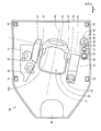
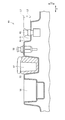
- FIG. 1 It is a side view which shows roughly the structure of the bulldozer in embodiment of this invention. It is a top view which shows roughly the structure inside the cab shown in FIG. It is an expanded sectional view which shows the detail of a structure of a side shelf. It is a perspective view of an engine stop switch. It is sectional drawing of a side shelf which shows the state which operated the engine stop switch.
- the front side (front side) of the operator is the front side of the bulldozer 10
- the rear side of the operator is the rear side of the bulldozer 10.
- the left side of the operator in the state is the left side of the bulldozer 10
- the right side of the operator in the seated state is the right side of the bulldozer 10.
- the front-rear direction means the front-rear direction viewed from the driver seated on the driver's seat of the cab 30.
- the left-right direction, the vehicle width direction, or the side is the left-right direction as viewed from the driver.
- the front-rear direction is indicated by an arrow X
- the left-right direction is indicated by an arrow Y
- the up-down direction is indicated by an arrow Z in the figure.
- FIG. 1 is a side view schematically showing a configuration of a bulldozer 10 in an embodiment of the present invention.
- the bulldozer 10 of this embodiment mainly includes a traveling device, a vehicle body 1, a blade 2, and a ripper device 7.
- the traveling device has a pair of left and right crawler type traveling bodies 3 separated in the vehicle width direction (Y direction).
- the vehicle body 1 is disposed between a pair of left and right crawler type traveling bodies 3.
- the blade 2 is disposed at a front position of the vehicle body 1.
- the ripper device 7 is disposed at a rear position of the vehicle body 1.
- the vehicle body 1 has a cab (operator's cab) 30 and an engine compartment 20.
- the cab 30 is disposed at the rear upper part of the vehicle body 1.
- the engine compartment 20 is disposed in front of the cab 30.
- the engine chamber 20 is disposed between the cab 30 and the blade 2.
- An engine 21 is accommodated in the engine chamber 20.
- the cab 30 has a driver's seat for a driver to sit inside, and is configured to surround the driver's seat.
- the bulldozer 10 has a blade 2 in front as a working machine.
- the blade 2 is a working machine for performing operations such as excavation and leveling of earth and sand.
- the blade 2 is supported by the frame 4 on both the left and right sides.
- the blade 2 is driven by a tilt cylinder 5 and a lift cylinder 6.
- the bulldozer 10 has a ripper device 7 at the rear as a working machine.
- the ripper device 7 is a working machine for penetrating and crushing hard materials such as rocks.
- the ripper device 7 has a shank 12.
- a ripper point 11 is provided at the lower end of the shank 12.
- the ripper device 7 pierces the ripper point 11 into a rock or the like, and performs cutting or crushing by a traction force by the traveling device.
- the ripper device 7 is driven by a lift cylinder 8 and a tilt cylinder 9.
- FIG. 2 is a plan view schematically showing an internal configuration of the cab 30 shown in FIG.
- a driver's seat 31 is disposed inside the cab 30.
- the cab 30 has a roof portion disposed so as to cover the driver's seat 31 and a plurality of pillars that support the roof portion. Each pillar extends in the vertical direction (Z direction) and is connected to the floor portion and the roof portion of the cab 30.
- the plurality of pillars have front pillars 51 and 52 and rear pillars 53 and 54.
- the front pillars 51 and 52 are disposed in front of the driver's seat 31 in the front-rear direction (X direction).
- the rear pillars 53 and 54 are disposed behind the driver seat 31 in the front-rear direction (X direction).
- the front pillar 51 and the rear pillar 53 are arranged on the right side with respect to the driver's seat 31 in the vehicle width direction (Y direction).
- the front pillar 52 and the rear pillar 54 are arranged on the left side with respect to the driver's seat 31 in the vehicle width direction (Y direction).
- the driver's seat 31 is arranged near the approximate center of the cab 30.
- the driver's seat 31 has a seat portion 32, a back portion 33, and a headrest 34.
- An operator boarding the cab 30 is seated on the seat portion 32.
- the back portion 33 is provided in order for the operator seated on the seating portion 32 to lean his back.
- the back part 33 is a backrest.
- left and right end portions of the back surface portion 33 are provided with side supports protruding forward.
- a headrest 34 is attached to the upper end of the back surface portion 33. The headrest 34 protects the operator's head from impact.
- a front console 46 is arranged in front of the driver's seat 31 in the cab 20.
- An operation panel, instruments, switches, and the like are attached to the front console 46.
- the right console 41 is arranged on the right side of the driver's seat 31 in the cab 30. On the right console 41, a lever for operating the work machine is provided. A blade operation lever 42 for operating the blade 2 and a ripper operation lever 43 for operating the ripper device 7 are attached to the right console 41.
- the blade operation lever 42 is disposed on the front side of the right console 41.
- the ripper operation lever 43 is disposed on the right rear side of the blade operation lever 42.
- the right armrest 47 is arranged on the right side of the driver's seat 31 in the cab 30.
- the right armrest 47 is disposed laterally with respect to the driver seat 31.
- the right armrest 47 is disposed between the driver seat 31 and the right console 41 in the vehicle width direction (Y direction).
- the right armrest 47 is disposed between the ripper operation lever 43 and the driver seat 31.
- the left console 44 is arranged on the left side of the driver's seat 31 in the cab 20. On the left console 44, a lever for running the bulldozer 10 is provided. A travel operation lever 45 is attached to the left console 44. The travel operation lever 45 is disposed on the front side of the left console 44. The rear side of the left console 44 is provided as a left armrest.
- the belt accommodating part 35 which accommodates a seatbelt is arrange
- the belt accommodating portion 35 is disposed between the driver seat 31 and the right armrest 47.
- a locking portion 36 that locks the seat belt is disposed on the left side of the driver's seat 31 in the cab 20.
- the locking portion 36 is disposed between the driver's seat 31 and the left console 44.
- the seat belt is pulled out from the belt accommodating portion 35, and the locking member at the tip of the seat belt is locked to the locking portion 36, so that the seat belt is mounted around the trunk of the driver seated on the driver seat 31.
- a side shelf 60 is arranged on the left side of the driver's seat 31 in the cab 30.
- the side shelf 60 is disposed laterally with respect to the driver seat 31.
- the side shelf 60 is disposed on the left rear side of the driver seat 31.
- the side shelf 60 has a first attachment portion 55 and a second attachment portion 61.
- the first attachment portion 55 is provided with a cup holder 56, an ashtray 57, a cigar lighter 58, and an external connection terminal 59.
- the cup holder 56, the ashtray 57, the cigar lighter 58, and the external connection terminal 59 are concentrated on the first attachment portion 55.
- the cup holder 56, the ashtray 57, the cigarette lighter 58, and the external connection terminal 59 constitute a handling unit that is handled by a driver seated on the driver's seat 31.
- the second mounting portion 61 is disposed adjacent to the first mounting portion 55.
- the second attachment portion 61 is adjacent to the rear of the first attachment portion 55.
- the second mounting portion 61 is provided with an engine stop switch 62.
- the engine stop switch 62 is a switch for urgently stopping the engine 21 (FIG. 1). Only the engine stop switch 62 is disposed on the upper surface of the second mounting portion 61. No equipment other than the engine stop switch 62 is disposed on the upper surface of the second mounting portion 61.
- the midline ML of the driver's seat 31 represents the midline ML of the driver's seat 31.
- the midline is a virtual line that divides the driver's seat 31 into left and right halves.
- the median line ML passes through the left and right centers of the driver's seat 31.
- the median line ML passes through the left and right centers of the driver's seat 31.
- the median line ML passes through the center of the driver seat 31 and extends to a position that equally divides the driver seat 31.
- the median line ML is on the symmetry plane.
- the midline ML may be a line that equally divides a member having a bilaterally symmetric shape that constitutes a part of the driver's seat 31.
- the median line ML may be a line that equally divides a part of the member constituting the part of the driver's seat 31 having a symmetrical shape.
- the median line ML may be a line that equally divides the seating portion 32, may be a line that equally divides the back surface portion 33, or may be a line that equally divides the headrest 34.
- the midline ML of the driver's seat 31 is inclined with respect to the front-rear direction (X direction) of the cab 30 so as to go to the right side toward the front and to the left side toward the rear.
- the driver's seat 31 is fixed at a position where the seated driver faces in a direction inclined rightward with respect to the front in the front-rear direction of the bulldozer in plan view.
- FIG. 3 is an enlarged cross-sectional view showing details of the configuration of the side shelf 60.
- FIG. 3 shows a cup holder 56, an ashtray 57, and a cigarette lighter 58 provided on the first mounting portion 55.
- FIG. 3 also shows an engine stop switch 62 provided on the second mounting portion 61.
- the second attachment portion 61 is substantially behind the vertical line PL in plan view.
- the engine stop switch 62 is behind the vertical line PL in plan view.
- the vertical line PL passes through the rearmost portion of the back surface 33a.
- the vertical line PL is not limited to the position shown in FIG. 2, and may pass through any part of the back surface part 33, for example, the rearmost part.
- a line L1 indicated by a two-dot chain line in FIG. 3 indicates the position of the upper surface of the first attachment portion 55.
- a line L ⁇ b> 2 indicated by a two-dot chain line in FIG. 3 indicates the position of the upper surface of the second attachment portion 61.
- the vertical position of the upper surface of the second mounting portion 61 is lower than the upper surface of the first mounting portion 55.
- a step of height H shown in FIG. 3 is formed between the upper surface of the first mounting portion 55 and the upper surface of the second mounting portion 61.
- the engine stop switch 62 is a push button switch. The opening / closing operation of the switch is performed by pushing the engine stop switch 62 by hand.
- the vertical position of the top surface of the engine stop switch 62 is the same as the upper surface of the first mounting portion 55. The position of the top surface of the engine stop switch 62 in the vertical direction may be lower than the top surface of the first mounting portion 55. The vertical position of the top surface of the engine stop switch 62 is below the top surface of the first mounting portion 55.
- a wall portion 63 that connects the upper surface of the first mounting portion 55 and the upper surface of the second mounting portion 61 is provided at the rear end of the first mounting portion 55 and the front end of the second mounting portion 61.
- the engine stop switch 62 faces the wall portion 63.
- FIG. 4 is a perspective view of the engine stop switch 62. As shown in FIG. 4, only the engine stop switch 62 is disposed on the upper surface of the second mounting portion 61. No member or device is provided around the engine stop switch 62 except that a wall 63 that connects the first mounting portion 55 and the second mounting portion 61 is provided.
- the second mounting portion 61 is a flat surface, but may have a curve or a convex portion that does not hinder the operation of the engine stop switch 62.
- a wall 63 is provided in one direction around the engine stop switch 62, and the other three sides around the engine stop switch 62 are open.
- a wall 63 is provided in front of the engine stop switch 62, and no wall is provided on the right, left, and rear of the engine stop switch 62.
- the engine stop switch 62 is disposed so as to be opened in three directions, rightward, leftward and rearward. There are no structures or devices that obstruct the operation of the engine stop switch 62 in the three directions on the right, left, and rear of the engine stop switch 62.
- FIG. 5 is a sectional view of the side shelf 60 showing a state in which the engine stop switch 62 is operated.
- the engine stop switch 62 is a push button switch, and FIG. 5 shows a state where the engine stop switch 62 is pushed and moved downward.
- the vertical position of the top surface of the engine stop switch 62 is lower than the upper surface of the first mounting portion 55.
- the top surface of the engine stop switch 62 is disposed at a position lower than the line L1 indicating the position of the upper surface of the first mounting portion 55.
- the top surface of the engine stop switch 62 is between a line L1 indicating the position of the upper surface of the first mounting portion 55 and a line L2 indicating the position of the upper surface of the second mounting portion 61. It is arranged in the area.
- the vertical position of the top surface of the engine stop switch 62 is higher than the upper surface of the second mounting portion 61.
- the vertical position of the top surface of the engine stop switch 62 is higher than the top surface of the second mounting portion 61.
- the cab 30 of this embodiment includes a driver's seat 31 and a side shelf 60.
- the side shelf 60 is disposed on the left side in the vehicle width direction (Y direction) with respect to the driver seat 31.
- the side shelf 60 has a first mounting portion 55.
- the first attachment portion 55 is provided with a cup holder 56, an ashtray 57, a cigar lighter 58, and an external connection terminal 59.
- the cup holder 56, the ashtray 57, the cigarette lighter 58, and the external connection terminal 59 constitute a handling unit that is handled by a driver seated on the driver's seat 31.
- the side shelf 60 has a second mounting portion 61.
- the second attachment portion 61 is provided with an engine stop switch 62 for urgently stopping the engine 21.
- the second attachment portion 61 is adjacent to the first attachment portion 55.
- the vertical position of the upper surface of the second mounting portion 61 is lower than the upper surface of the first mounting portion 55.
- the three sides around the engine stop switch 62 are opened.
- the engine stop switch 62 Since the engine stop switch 62 is disposed on the side shelf 60, the operator seated in the driver's seat 31 can operate the engine stop switch 62 by reaching the second mounting portion 61.
- a wall 63 is provided in front, but the other three sides are not provided with a wall and are open. There is no cover covering the engine stop switch 62, and the engine stop switch 62 is opened.
- the structure around the engine stop switch 62 does not hinder the operation of the operator. Therefore, the operator can quickly stop the engine 21 by operating the engine stop switch 62 quickly.
- the engine stop switch 62 is provided in the second mounting portion 61.
- the second attachment portion 61 is disposed at a position different from the first attachment portion 55 provided with a handling portion that is handled by an operator. Thereby, when an operator handles a handling part, it can suppress contacting the engine stop switch 62 accidentally.
- the vertical position of the top surface of the engine stop switch 62 is below the upper surface of the first mounting portion 55.
- the engine stop switch 62 is a pushbutton switch, and the position of the top surface of the engine stop switch 62 when the engine stop switch 62 is pressed is higher than the upper surface of the first mounting portion 55. Low. Thereby, when an operator handles a handling part, it can suppress contacting the engine stop switch 62 accidentally, and the erroneous operation of the engine stop switch 62 can be suppressed.
- the second mounting portion 61 is adjacent to the rear of the first mounting portion 55.
- the side shelf 60 by providing the first mounting portion 55 in the front and the second mounting portion 61 in the rear, it is possible to prevent the operator from unintentionally contacting the engine stop switch 62 when handling the handling portion. . Accordingly, erroneous operation of the engine stop switch 62 can be suppressed.
- only the engine stop switch 62 is disposed on the upper surface of the second mounting portion 61. Thereby, when an operator operates another apparatus or handles another member, it can suppress contacting the engine stop switch 62 unintentionally. Accordingly, erroneous operation of the engine stop switch 62 can be suppressed.
- the midline ML that equally divides the driver's seat 31 in a plan view is inclined with respect to the front-rear direction of the cab 30 so as to go to the right side toward the front and to the left side toward the rear.
- the side shelf 60 is disposed on the left rear side of the driver seat 31. By arranging the side shelf 60 at a position farther from the driver seated on the driver's seat 31, it is possible to suppress the driver from erroneously contacting the engine stop switch 62, and to suppress erroneous operation of the engine stop switch 62. Can do.
- the side shelf 60 is arranged at a position where the operator can reach his / her hand by rotating his / her body. Accordingly, in an emergency, the operator can rotate the body and operate the engine stop switch 62.
- the work vehicle of this embodiment includes an engine 21 and any one of the cabs 30 described above.
- An operator seated in the cab 30 can operate the engine stop switch 62 to urgently stop the engine 21.
- erroneous operation of the engine stop switch 62 can be suppressed.
- the periphery of the second mounting portion 61 provided with the engine stop switch 62 is lower than the upper surface of the second mounting portion 61 except for the wall portion 63. It extends to.
- the structure is not limited to this configuration, and a structure that slightly protrudes upward from the upper surface of the second mounting portion 61 may be provided on three sides around the second mounting portion 61 excluding the wall portion 63.
- the height at which the structure projects from the upper surface of the second mounting portion 61 is defined to be smaller than the distance from the upper surface of the second mounting portion 61 to the movable portion of the engine stop switch 62.
- the engine stop switch 62 is not limited to the push button switch described above, and may be any other type of switch such as a toggle switch. However, because of the characteristic of the engine stop switch 62 that requires an emergency operation, a push button switch that can be switched on and off by pressing the button is suitable as the engine stop switch 62.
Landscapes
- Engineering & Computer Science (AREA)
- Mining & Mineral Resources (AREA)
- Civil Engineering (AREA)
- General Engineering & Computer Science (AREA)
- Structural Engineering (AREA)
- Chemical & Material Sciences (AREA)
- Combustion & Propulsion (AREA)
- Transportation (AREA)
- Mechanical Engineering (AREA)
- Component Parts Of Construction Machinery (AREA)
- Body Structure For Vehicles (AREA)
Abstract
Priority Applications (4)
| Application Number | Priority Date | Filing Date | Title |
|---|---|---|---|
| CN201580003133.7A CN106488856A (zh) | 2015-06-09 | 2015-06-09 | 驾驶室以及作业车辆 |
| US15/036,449 US9885170B2 (en) | 2015-06-09 | 2015-06-09 | Cab and work vehicle |
| PCT/JP2015/066552 WO2016199217A1 (fr) | 2015-06-09 | 2015-06-09 | Cabine et engin de chantier |
| JP2015556277A JP5926869B1 (ja) | 2015-06-09 | 2015-06-09 | キャブおよび作業車両 |
Applications Claiming Priority (1)
| Application Number | Priority Date | Filing Date | Title |
|---|---|---|---|
| PCT/JP2015/066552 WO2016199217A1 (fr) | 2015-06-09 | 2015-06-09 | Cabine et engin de chantier |
Publications (1)
| Publication Number | Publication Date |
|---|---|
| WO2016199217A1 true WO2016199217A1 (fr) | 2016-12-15 |
Family
ID=56069568
Family Applications (1)
| Application Number | Title | Priority Date | Filing Date |
|---|---|---|---|
| PCT/JP2015/066552 Ceased WO2016199217A1 (fr) | 2015-06-09 | 2015-06-09 | Cabine et engin de chantier |
Country Status (4)
| Country | Link |
|---|---|
| US (1) | US9885170B2 (fr) |
| JP (1) | JP5926869B1 (fr) |
| CN (1) | CN106488856A (fr) |
| WO (1) | WO2016199217A1 (fr) |
Families Citing this family (7)
| Publication number | Priority date | Publication date | Assignee | Title |
|---|---|---|---|---|
| US9816251B2 (en) * | 2015-06-08 | 2017-11-14 | Komatsu Ltd. | Cab and bulldozer |
| JP6451707B2 (ja) * | 2016-09-02 | 2019-01-16 | コベルコ建機株式会社 | 建設機械 |
| WO2019131721A1 (fr) * | 2017-12-27 | 2019-07-04 | 株式会社クボタ | Équipement de travail et son procédé de production |
| JP7281869B2 (ja) * | 2018-03-14 | 2023-05-26 | 株式会社小松製作所 | 作業車両 |
| JP7195872B2 (ja) * | 2018-10-26 | 2022-12-26 | 株式会社小松製作所 | 作業車両 |
| GB2579075B (en) * | 2018-11-19 | 2021-06-16 | Caterpillar Inc | Work machine with sensor enabled user control |
| KR102294109B1 (ko) * | 2020-12-21 | 2021-08-25 | 안국수 | 건설장비의 다관절 작동형 콘솔박스 |
Citations (6)
| Publication number | Priority date | Publication date | Assignee | Title |
|---|---|---|---|---|
| JPH0441561U (fr) * | 1990-07-31 | 1992-04-08 | ||
| JP2001026947A (ja) * | 1999-07-15 | 2001-01-30 | Hitachi Constr Mach Co Ltd | 建設車両のフロントコンソール |
| JP2007162313A (ja) * | 2005-12-13 | 2007-06-28 | Hitachi Constr Mach Co Ltd | 建設機械 |
| JP2009137538A (ja) * | 2007-12-10 | 2009-06-25 | Hitachi Constr Mach Co Ltd | 作業機械の室内灯装置 |
| JP2011116253A (ja) * | 2009-12-03 | 2011-06-16 | Hitachi Constr Mach Co Ltd | 建設機械 |
| WO2012060355A1 (fr) * | 2010-11-05 | 2012-05-10 | 株式会社小松製作所 | Dispositif d'indication de statut de véhicule et procédé d'indication de statut de véhicule pour machine de construction |
Family Cites Families (10)
| Publication number | Priority date | Publication date | Assignee | Title |
|---|---|---|---|---|
| US2907853A (en) * | 1958-01-30 | 1959-10-06 | Estel M Warren | Safety switch |
| JP3529478B2 (ja) | 1995-03-13 | 2004-05-24 | ヤンマー株式会社 | トラクター |
| JPH10155350A (ja) | 1996-11-29 | 1998-06-16 | Seirei Ind Co Ltd | コンバインにおける排出オーガの誤操作防止装置 |
| KR100655191B1 (ko) * | 2000-03-01 | 2006-12-08 | 티씨엠 가부시키가이샤 | 산업용 차량 |
| JP4093454B2 (ja) * | 2002-01-09 | 2008-06-04 | 新キャタピラー三菱株式会社 | 滑り止め材 |
| DE10348884A1 (de) * | 2003-10-14 | 2005-05-25 | Pilz Gmbh & Co. Kg | Sicherheitsschalter, insbesondere Not-Aus-Schalter, zum sicheren Abschalten eines gefahrbringenden Gerätes |
| JP4595897B2 (ja) * | 2006-07-24 | 2010-12-08 | 株式会社豊田自動織機 | 車両用回転シート |
| US8434562B2 (en) * | 2007-12-13 | 2013-05-07 | Komatsu Ltd. | Ripper operating device |
| US8985263B2 (en) * | 2011-03-01 | 2015-03-24 | Joy Mm Delaware, Inc. | Seat module for a mining vehicle |
| JP5411382B1 (ja) * | 2013-07-19 | 2014-02-12 | 株式会社小松製作所 | 作業車両 |
-
2015
- 2015-06-09 JP JP2015556277A patent/JP5926869B1/ja active Active
- 2015-06-09 CN CN201580003133.7A patent/CN106488856A/zh not_active Withdrawn
- 2015-06-09 US US15/036,449 patent/US9885170B2/en active Active
- 2015-06-09 WO PCT/JP2015/066552 patent/WO2016199217A1/fr not_active Ceased
Patent Citations (6)
| Publication number | Priority date | Publication date | Assignee | Title |
|---|---|---|---|---|
| JPH0441561U (fr) * | 1990-07-31 | 1992-04-08 | ||
| JP2001026947A (ja) * | 1999-07-15 | 2001-01-30 | Hitachi Constr Mach Co Ltd | 建設車両のフロントコンソール |
| JP2007162313A (ja) * | 2005-12-13 | 2007-06-28 | Hitachi Constr Mach Co Ltd | 建設機械 |
| JP2009137538A (ja) * | 2007-12-10 | 2009-06-25 | Hitachi Constr Mach Co Ltd | 作業機械の室内灯装置 |
| JP2011116253A (ja) * | 2009-12-03 | 2011-06-16 | Hitachi Constr Mach Co Ltd | 建設機械 |
| WO2012060355A1 (fr) * | 2010-11-05 | 2012-05-10 | 株式会社小松製作所 | Dispositif d'indication de statut de véhicule et procédé d'indication de statut de véhicule pour machine de construction |
Also Published As
| Publication number | Publication date |
|---|---|
| JP5926869B1 (ja) | 2016-05-25 |
| JPWO2016199217A1 (ja) | 2017-06-22 |
| CN106488856A (zh) | 2017-03-08 |
| US20170167111A1 (en) | 2017-06-15 |
| US9885170B2 (en) | 2018-02-06 |
Similar Documents
| Publication | Publication Date | Title |
|---|---|---|
| JP5926869B1 (ja) | キャブおよび作業車両 | |
| US9816251B2 (en) | Cab and bulldozer | |
| JP6971773B2 (ja) | 作業車両のキャブ、作業車両およびホイールローダ | |
| TWI540956B (zh) | Work car | |
| US20180067513A1 (en) | Operation device of work vehicle | |
| CN101884021A (zh) | 松土器的操作装置 | |
| JP5536964B1 (ja) | 建設機械用キャブおよび建設機械 | |
| JP2021008139A (ja) | 自動運転車両の操作装置 | |
| JP6824118B2 (ja) | 作業車両用キャブおよび作業車両 | |
| US20150211207A1 (en) | Construction Machine | |
| US20160304113A1 (en) | Steering column for machine | |
| JP6639986B2 (ja) | コンバイン | |
| JP2018044328A (ja) | 作業車両 | |
| US10125473B2 (en) | Bulldozer | |
| JPWO2017141419A1 (ja) | キャブおよび作業車両 | |
| JP2019069708A (ja) | トラクタ | |
| JP5576351B2 (ja) | 作業機 | |
| JP7552480B2 (ja) | 建設機械 | |
| JP6166967B2 (ja) | 作業車両 | |
| JP2002316789A (ja) | 建設機械の運転室 | |
| JP2000054436A (ja) | 作業機械における油圧ロックレバー装置 | |
| WO2024176577A1 (fr) | Structure de poste de pilotage pour engin de chantier | |
| WO2021205781A1 (fr) | Cabine de véhicule de travail, véhicule de travail et bouteur | |
| JP2016155468A (ja) | カバー体構造 | |
| JP2005008016A (ja) | トラクタ |
Legal Events
| Date | Code | Title | Description |
|---|---|---|---|
| ENP | Entry into the national phase |
Ref document number: 2015556277 Country of ref document: JP Kind code of ref document: A |
|
| WWE | Wipo information: entry into national phase |
Ref document number: 15036449 Country of ref document: US |
|
| 121 | Ep: the epo has been informed by wipo that ep was designated in this application |
Ref document number: 15894902 Country of ref document: EP Kind code of ref document: A1 |
|
| NENP | Non-entry into the national phase |
Ref country code: DE |
|
| 122 | Ep: pct application non-entry in european phase |
Ref document number: 15894902 Country of ref document: EP Kind code of ref document: A1 |