WO2016203892A1 - Dispositif amplificateur - Google Patents
Dispositif amplificateur Download PDFInfo
- Publication number
- WO2016203892A1 WO2016203892A1 PCT/JP2016/064675 JP2016064675W WO2016203892A1 WO 2016203892 A1 WO2016203892 A1 WO 2016203892A1 JP 2016064675 W JP2016064675 W JP 2016064675W WO 2016203892 A1 WO2016203892 A1 WO 2016203892A1
- Authority
- WO
- WIPO (PCT)
- Prior art keywords
- shell
- chamber
- center
- center shell
- booster
- Prior art date
- Legal status (The legal status is an assumption and is not a legal conclusion. Google has not performed a legal analysis and makes no representation as to the accuracy of the status listed.)
- Ceased
Links
Images





Classifications
-
- B—PERFORMING OPERATIONS; TRANSPORTING
- B60—VEHICLES IN GENERAL
- B60T—VEHICLE BRAKE CONTROL SYSTEMS OR PARTS THEREOF; BRAKE CONTROL SYSTEMS OR PARTS THEREOF, IN GENERAL; ARRANGEMENT OF BRAKING ELEMENTS ON VEHICLES IN GENERAL; PORTABLE DEVICES FOR PREVENTING UNWANTED MOVEMENT OF VEHICLES; VEHICLE MODIFICATIONS TO FACILITATE COOLING OF BRAKES
- B60T13/00—Transmitting braking action from initiating means to ultimate brake actuator with power assistance or drive; Brake systems incorporating such transmitting means, e.g. air-pressure brake systems
- B60T13/10—Transmitting braking action from initiating means to ultimate brake actuator with power assistance or drive; Brake systems incorporating such transmitting means, e.g. air-pressure brake systems with fluid assistance, drive, or release
- B60T13/24—Transmitting braking action from initiating means to ultimate brake actuator with power assistance or drive; Brake systems incorporating such transmitting means, e.g. air-pressure brake systems with fluid assistance, drive, or release the fluid being gaseous
- B60T13/46—Vacuum systems
- B60T13/52—Vacuum systems indirect, i.e. vacuum booster units
- B60T13/56—Vacuum systems indirect, i.e. vacuum booster units with two-chamber booster units
-
- B—PERFORMING OPERATIONS; TRANSPORTING
- B60—VEHICLES IN GENERAL
- B60T—VEHICLE BRAKE CONTROL SYSTEMS OR PARTS THEREOF; BRAKE CONTROL SYSTEMS OR PARTS THEREOF, IN GENERAL; ARRANGEMENT OF BRAKING ELEMENTS ON VEHICLES IN GENERAL; PORTABLE DEVICES FOR PREVENTING UNWANTED MOVEMENT OF VEHICLES; VEHICLE MODIFICATIONS TO FACILITATE COOLING OF BRAKES
- B60T13/00—Transmitting braking action from initiating means to ultimate brake actuator with power assistance or drive; Brake systems incorporating such transmitting means, e.g. air-pressure brake systems
- B60T13/10—Transmitting braking action from initiating means to ultimate brake actuator with power assistance or drive; Brake systems incorporating such transmitting means, e.g. air-pressure brake systems with fluid assistance, drive, or release
- B60T13/24—Transmitting braking action from initiating means to ultimate brake actuator with power assistance or drive; Brake systems incorporating such transmitting means, e.g. air-pressure brake systems with fluid assistance, drive, or release the fluid being gaseous
- B60T13/46—Vacuum systems
- B60T13/52—Vacuum systems indirect, i.e. vacuum booster units
- B60T13/567—Vacuum systems indirect, i.e. vacuum booster units characterised by constructional features of the casing or by its strengthening or mounting arrangements
Definitions
- the present invention relates to a booster used in a vehicle brake device.
- a pneumatic booster is provided between a brake pedal and a master cylinder.
- This type of pneumatic booster boosts the pedal force applied from the brake pedal to the input rod according to the pressure difference between the internal constant pressure chamber and the variable pressure chamber.
- the booster according to Patent Document 1 holds the diaphragm by engaging the convex portion of the diaphragm (power piston) in the engagement holes respectively provided in the front shell and the rear shell constituting the outer shell.
- the diaphragm is formed of an elastic material such as rubber, it is difficult to position the shell in the circumferential direction even if this configuration is applied.
- an object of the present invention is to provide a booster that facilitates positioning of the shell in the circumferential direction.
- a booster includes a housing whose interior is defined by a front shell, a rear shell, and a center shell into a front chamber and a rear chamber, and each of the front chamber and the rear chamber has a power piston.
- the front chamber is partitioned into a constant pressure chamber and a variable pressure chamber
- the rear chamber is partitioned into a constant pressure chamber and a variable pressure chamber
- the booster is also A rod member passing through the housing and having one end for fixing to the master cylinder and the other end for connection to the vehicle;
- One of the front shell and the rear shell and the center shell include a part of the outer peripheral edge of the one shell and a part of the outer peripheral edge of the center shell in the circumferential direction of the center shell.
- a circumferential direction restricting portion for positioning is formed.
- the shell can be easily positioned in the circumferential direction.
- FIG. 3 is an exploded cross-sectional view illustrating a state in which a front shell, a center shell, and a rear shell in FIG. 2 are disassembled.
- the bottom view which looked at the front shell, center shell, and rear shell in FIG. 2 from the direction of arrows IV-IV.
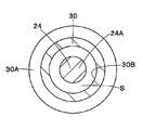
- Sectional drawing which looked at the cylindrical member in FIG. 1 from the arrow VV direction.
- the front view which shows a center shell as a single unit. Sectional drawing similar to FIG. 2 which shows the front shell, center shell, and rear shell by 2nd Embodiment.
- FIG. 3 is an exploded cross-sectional view illustrating a state in which a front shell, a center shell, and a rear shell in FIG. 2 are disassembled.
- the bottom view which looked at the front shell, center shell, and rear shell in FIG. 2 from the direction of arrows IV-IV.
- Sectional drawing which looked at the cylindrical member in FIG. 1 from the arrow VV direction.
- the front view which shows a
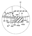
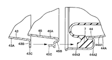
- FIG. 8 is an exploded cross-sectional view illustrating a state in which the front shell, the center shell, and the rear shell in FIG. 7 are exploded. Sectional drawing which looked at the front shell, center shell, and rear shell in FIG. 7 from the arrow IX-IX direction. The front view which shows a center shell as a single unit.
- a pneumatic booster 1 has a housing 2 that constitutes an outer shell thereof.
- the housing 2 is positioned on the front side of a vehicle (not shown) and on the rear side thereof.
- the rear shell 4 is configured.
- a center shell 5 is provided between the front shell 3 and the rear shell 4 to define the inside of the housing 2 into two chambers, a front chamber A and a rear chamber B.
- the shells 3, 4, and 5 are attached to each other on the outer peripheral side in an airtight state.
- the front shell 3 includes a front wall 3A serving as a mounting surface for a master cylinder (not shown), and an outer peripheral cylindrical portion 3B extending rearward from a radially outer end portion of the front wall 3A. Yes.
- a cylindrical recess 3A1 for accommodating a part of the master cylinder is formed at the center of the front wall 3A.
- the cylindrical recess 3A1 is provided with an annular seal member (not shown) that hermetically seals with the master cylinder. This sealing member seals the constant pressure chamber A1 in the housing 2 in an airtight state against the outside atmosphere.
- the front wall 3A has a negative pressure introduction communicating with a front side insertion hole 3A2 which is located radially outside of the cylindrical recess 3A1 and through which a rod member 24 described later is inserted, and a negative pressure introducing tube 23 described later.
- a hole 3A3 is formed.
- a step 3B1 is formed at an intermediate position in the front and rear directions (axial direction) of the outer peripheral cylinder portion 3B.
- a power piston 6 to be described later is fixed to the step portion 3B1 with a center shell 5 by means such as press fitting.
- a front shell side bent piece portion 3B2 that is bent toward the outer side in the radial direction and is in contact with the center shell side bent piece portion 5C of the center shell 5 is formed on the rear end side of the outer peripheral cylindrical portion 3B. .
- the rear shell 4 includes a rear wall 4A serving as a mounting surface for a vehicle body (not shown), a rear cylinder portion 4B protruding outward in the axial direction from a center portion of the rear wall 4A, and a radially outer end of the rear wall 4A. And an outer peripheral cylindrical portion 4C extending forward from the portion.
- the rear wall 4A is formed with a rear side insertion hole 4A1 that is located radially outside the rear cylinder portion 4B and into which a rod member 24 described later is inserted.
- An annular stepped portion 4B1 is provided in the middle of the rear cylinder portion 4B in the axial direction (length direction).
- a stop key 18 (described later) abuts on the stepped portion 4B1 when a push operation of the input rod 10 (described later) is released, thereby restricting return positions of a valve body 8 and a plunger 16 (described later).
- the outer peripheral cylindrical portion 4C includes a cylindrical portion 4C1 that extends forward from the rear wall 4A, an annular step portion 4C2 that is bent radially outward from the front end of the cylindrical portion 4C1, and the annular step portion 4C2. It is comprised by the extended cylinder part 4C3 extended toward the front from the radial direction outer side edge part.
- a power piston 7 described later is fixed to the annular step portion 4C2 between the center shell 5 and the annular step portion 4C2.
- the inner diameter dimension of the extending cylindrical portion 4C3 of the rear shell 4 is formed larger than the outer diameter dimension of the front shell 3 (front shell side bent piece portion 3B2). And the front end side of the extended cylinder part 4C3 is extended toward the front rather than the front shell side bending piece part 3B2 of the front shell 3.
- the front shell 3, the rear shell 4, and the center shell 5 are caulked radially inward at a plurality of locations (for example, 15 to 20 locations) that are spaced apart in the circumferential direction on the front end side of the extended cylindrical portion 4 C 3. Axial locking is made.
- an axial groove 4 ⁇ / b> D opening forward in the axial direction is formed in a U-shape or a U-shape in a part (for example, one place) of the outer peripheral edge of the extended cylindrical portion 4 ⁇ / b> C ⁇ b> 3 of the rear shell 4. It is formed in a shape.
- the axial groove 4 ⁇ / b> D is formed at a position corresponding to a later-described protruding piece portion 5 ⁇ / b> D formed in the center shell 5. As shown in FIGS.
- the axial dimension L of the axial groove 4D is such that the power piston 7 extends from the front end of the extended cylindrical portion 4C3 in a state where the power piston 7 is press-fitted or fitted into the annular stepped portion 4C2. It extends until it reaches a rear position from the front end.
- the circumferential dimension of the axial groove 4D is slightly larger than the circumferential dimension of the protruding piece 5D.
- the axial groove 4D is not limited to one place on the outer peripheral edge of the extended cylindrical portion 4C3, and may be formed at a plurality of places spaced in the circumferential direction on the outer peripheral edge of the rear shell 4.
- the center shell 5 is located between the front shell 3 and the rear shell 4, and includes a front chamber A formed in the housing 2 between the front shell 3 and the center shell 5, and the rear shell 4 and the center shell 5. It is defined in the rear chamber B formed between them.
- the center shell 5 includes a partition wall 5A located between the front wall 3A of the front shell 3 and the rear wall 4A of the rear shell 4, and a radially outer end portion of the partition wall 5A from the outer peripheral cylindrical portion 3B of the front shell 3.
- An outer peripheral cylindrical portion 5B extending rearward along the outer peripheral cylindrical portion 5B, bent outwardly in the radial direction from the rear end of the outer peripheral cylindrical portion 5B, and a front shell side bent piece portion 3B2 of the front shell 3 and the power piston 7
- the center shell side bent piece portion 5C located between them is included.
- a valve body insertion hole 5A1 through which a later-described valve body 8 is inserted is formed in the central portion of the partition wall 5A, and one end side of a later-described cylindrical member 30 is located at a position radially outside the valve body insertion hole 5A1.
- a cylindrical member mounting hole 5A2 is formed.
- the center shell side bent piece portion 5C is bent in a substantially U shape from the rear end of the outer peripheral cylindrical portion 5B, and the front end side is bent outward in the radial direction.
- the center shell side bent piece portion 5 ⁇ / b> C maintains the airtight state of the constant pressure chamber B ⁇ b> 1 when the rear surface abuts against the power piston 7.
- a protruding piece 5D is formed at a part of the center shell side bent piece 5C on the tip side in the circumferential direction.
- the protruding piece 5D protrudes radially outward at a part (for example, one location) of the outer peripheral edge of the center shell side bent piece 5C of the center shell 5. Is formed.
- the projecting piece 5D is formed for positioning the center shell together with the axial groove 4D of the rear shell 4. That is, the protruding piece portion 5D and the axial groove 4D constitute a circumferential direction regulating portion for positioning the center shell 5 in the circumferential direction.
- the length of the protruding piece 5D in the circumferential direction is slightly smaller than the length of the axial groove 4D in the rear shell 4 in the circumferential direction.
- the center shell 5 is positioned (stopped) in the circumferential direction.
- the protruding piece 5D is not limited to one place on the outer peripheral edge of the center shell side bent piece 5C, but a plurality of places (number corresponding to the axial groove 4D) spaced apart in the circumferential direction of the outer peripheral edge of the center shell 5. You may form in.
- a power piston 6 made of a diaphragm or the like is provided in the front chamber A in the housing 2.
- the power piston 6 has an outer peripheral side fixed between the front shell 3 and the center shell 5, and an inner peripheral side fixed to a later-described valve body 8.
- a shaft 24A of a rod member 24 described later is slidably inserted into the power piston 6.
- the front chamber A is a constant pressure chamber A1 between the front shell 3 and the power piston 6, and a variable pressure chamber A2 between the power piston 6 and the center shell 5.
- a power piston 7 made of a diaphragm or the like is provided in the rear chamber B in the housing 2.
- the power piston 7 is fixed in contact with the annular stepped portion 4C2 of the rear shell 4 and the center shell side bent piece portion 5C of the center shell 5, and the inner peripheral side of the power piston 7 is fixed to a later-described valve body 8.
- a cylindrical member 30 described later is slidably inserted into the power piston 7.
- a constant pressure chamber B1 is formed between the center shell 5 and the power piston 7, and a variable pressure chamber B2 is formed between the power piston 7 and the rear shell 4.
- the valve body 8 inserted into the rear cylinder portion 4B of the rear shell 4 is provided in the housing 2 so as to be displaceable in the axial direction (left and right directions in FIG. 1).
- the valve body 8 is formed in a stepped shape using a high-strength resin material, for example, by a main body portion 8A located on the master cylinder side and a small-diameter cylindrical portion 8B located on the vehicle body attachment side.
- the main body 8A of the valve body 8 is slidably inserted into the valve body insertion hole 5A1 of the center shell 5 via the seal member 9, and is connected (fixed) to the inner peripheral side of the power pistons 6 and 7. .
- the small-diameter cylindrical portion 8B of the valve body 8 extends from the rear cylindrical portion 4B of the rear shell 4 toward the outside of the housing 2 on the vehicle body attachment side (right side in FIG. 1).
- the valve body 8 is displaced in the axial direction in the housing 2 in conjunction with the displacement of the power pistons 6 and 7.
- the valve body 8 always communicates with the constant pressure chamber A1 and extends in the axial direction from the main body portion 8A toward the small-diameter cylindrical portion 8B, and a diameter that always communicates the axial passage 8C and the constant pressure chamber B1.
- a direction passage 8D is formed. That is, the constant pressure chamber A1 of the front chamber A and the constant pressure chamber B1 of the rear chamber B are always in communication with each other by the axial passage 8C and the radial passage 8D of the valve body 8.
- another radial passage 8E is formed at a position different from the axial passage 8C and the radial passage 8D.
- the radial passage 8E is always in communication with the variable pressure chamber A2 and the variable pressure chamber B2.
- the axial passage 8C, the radial passage 8D, and the radial passage 8E are connected to the constant pressure chambers A1 and B1 and the variable pressure chambers A2 and B2 with a poppet valve body 11 described later in accordance with the axial displacement of the valve body 8. Communicating and blocking via the plunger 16 and the like.
- a key insertion hole 8F is formed in the valve body 8 at a position corresponding to the step portion 4B1 of the rear shell 4.
- a stop key 18 described later is inserted into the key insertion hole 8F.
- the valve body 8 is formed with an annular valve seat portion 8G at the opening end of the axial passage 8C on the vehicle body mounting side.
- a poppet valve body 11, which will be described later, is configured to be separated from and seated on the valve seat portion 8G.
- the valve body 8 is integrally formed with a cylindrical projecting portion 8H that is located on the inner peripheral side of the main body portion 8A and projects in the axial direction toward the output rod 19 described later.
- the input rod 10 that extends in the valve body 8 in the axial direction protrudes outward from the rear cylinder portion 4B of the rear shell 4 on the vehicle body mounting side, and is inserted into the small diameter cylinder portion 8B of the valve body 8 on the master cylinder side (left side in FIG. 1).
- the input rod 10 is connected to a brake pedal (not shown) of the vehicle on the protruding end side, and is pushed in the direction of arrow C in FIG.
- a spherical portion 10A is integrally formed on the distal end side of the input rod 10, and the spherical portion 10A is connected to a plunger 16 described later using means such as caulking.
- the poppet valve body 11 provided in the small-diameter cylindrical portion 8B of the valve body 8 located on the outer peripheral side of the input rod 10 is formed in a substantially cylindrical shape by an elastic material.
- the body mounting side of the poppet valve body 11 is pressed and fixed to the inner peripheral side of the valve body 8 by a return spring 13 described later.
- the master cylinder side of the poppet valve body 11 is constantly urged by the weak spring 12 toward the valve seat portion 8G of the valve body 8. As a result, the poppet valve body 11 is separated from and seated on the valve seat portion 8G of the valve body 8 and a plunger 16 described later.
- the return spring 13 disposed between the small diameter cylindrical portion 8B of the valve body 8 and the input rod 10 constantly urges the input rod 10 toward the vehicle body mounting side with respect to the valve body 8.
- the valve body 8 moves in the direction of the arrow D in the housing 2 and is regulated by an initial position shown in FIG.
- the input rod 10 is pressed by the return spring 13 until it returns to the position).
- the filter 14 attached to the opening on the vehicle body mounting side of the valve body 8 cleans the air as working gas introduced from the outside of the housing 2 into the small diameter cylindrical portion 8B of the valve body 8, and dust or the like is generated in the housing 2. Suppresses intrusion.
- the protective boot 15 mounted on the outer peripheral side of the small-diameter cylindrical portion 8B of the valve body 8 is formed as an accordion-shaped cylindrical body with an elastic material, and protects the protruding end side of the valve body 8 from external dust and the like.
- the plunger 16 fixed to the spherical portion 10A of the input rod 10 is inserted on the inner peripheral side of the valve body 8 so as to be displaceable in the axial direction. That is, the plunger 16 is configured to be displaced in the axial direction integrally with the input rod 10.
- the plunger 16 introduces air (atmospheric pressure) introduced into the small-diameter cylindrical portion 8B of the valve body 8 via the filter 14 into the radial passage 8E side when the vehicle body mounting side is seated on and away from the poppet valve body 11. Or shut off the introduction of air.
- the plunger 16 is separated from and seated on the poppet valve body 11 to communicate and block the variable pressure chambers A2 and B2 with respect to the atmospheric pressure in the small diameter cylindrical portion 8B of the valve body 8. Further, when the poppet valve body 11 is separated from and seated on the valve seat portion 8G of the valve body 8, the variable pressure chambers A2 and B2 are connected to and disconnected from the constant pressure chambers A1 and B1.
- An annular groove is formed on the outer peripheral side of the plunger 16 at a position corresponding to the key insertion hole 8F of the valve body 8, and a stop key 18 described later is attached to the annular groove in an engaged state.
- the moving body 17 constituting a part of the plunger 16 moves (displaces) in the axial direction within the cylindrical protrusion 8H of the valve body 8.
- the master cylinder side of the moving body 17 is inserted into the inner peripheral side of the cylindrical projecting portion 8H of the valve body 8 and abuts on a reaction disk 22 described later.
- the stop key 18 that regulates the return position of the plunger 16 is formed using a substantially rectangular flat plate, and is engaged with the plunger 16 through the key insertion hole 8F of the valve body 8 in a loosely fitted state.
- the end portion of the stop key 18 protrudes from the valve body 8 by a certain dimension in the radial direction, and can come into contact with the annular step portion 4C2 of the rear shell 4. That is, when the pushing operation on the input rod 10 is released, the stop key 18 abuts on the annular step portion 4C2 of the rear shell 4, thereby restricting the return positions of the valve body 8 and the plunger 16 as shown in FIG.
- the output rod 19 that outputs to the master cylinder in a state where the pushing operation force of the input rod 10 is boosted is provided with a large-diameter flange portion 19A on the vehicle body mounting side, and the flange portion 19A has a reaction disk 22 described later.
- the tubular projecting portion 8H of the valve body 8 is fitted to the tubular projecting portion 8H so as to cover the tubular projecting portion 8H of the valve body 8.
- the output rod 19 is pushed with a large output in the direction of arrow C in FIG. 1 together with the valve body 8 when the input rod 10 is pushed. That is, the master cylinder side of the output rod 19 protrudes in the axial direction toward the cylindrical recess 3A1 of the front shell 3, and the piston of the master cylinder (output) is a force (output) obtained by multiplying the pushing operation force of the input rod 10. (Not shown) is configured to press in the axial direction.
- a spring receiver 20 provided on the inner peripheral side of the main body portion 8A of the valve body 8 is attached to the outer peripheral side of the cylindrical protruding portion 8H via the flange portion 19A of the output rod 19, and the flange portion 19A with respect to the cylindrical protruding portion 8H. It is the structure which performs removal prevention of this with the return spring 21.
- the return spring 21 is disposed between the spring receiver 20 and the cylindrical recess 3A1 of the front shell 3, and always urges the valve body 8 toward the vehicle body mounting side.
- the reaction disk 22 disposed between the cylindrical protruding portion 8H of the valve body 8 and the flange portion 19A of the output rod 19 is formed in a disk shape using a rubber material or the like that can be elastically deformed.
- the reaction disk 22 transmits the thrust generated in the valve body 8 to the output rod 19 due to the pressure difference generated between the constant pressure chambers A1, B1 and the variable pressure chambers A2, B2.
- the reaction disk 22 receives the reaction force from the output rod 19 and transmits a part of the reaction force to the input rod 10 side through the plunger 16 to give a response to the driver on the brake pedal side. .
- the negative pressure introduction pipe 23 provided on the front wall 3A of the front shell 3 is composed of a pipe or the like communicating with the negative pressure introduction hole 3A3 provided on the front wall 3A of the front shell 3.
- the intake manifold is connected via a check valve (both not shown).
- the negative pressure introduction pipe 23 holds the constant pressure chambers A1 and B1 at a pressure lower than the atmospheric pressure by guiding the negative pressure generated in the intake manifold during the operation of the engine into the constant pressure chambers A1 and B1. To do.
- the rod member 24 penetrates the housing 2, fixes the master cylinder on one end side (front end side), and connects to the vehicle body on the other end side (rear end side). That is, the rod member 24 is provided from the front shell 3 to the rear shell 4 through the center shell 5 and the pneumatic booster 1 is attached to the vehicle body (vehicle) and the master cylinder.
- two rod members 24 (only one is shown) are provided on the outer peripheral side of the small-diameter cylindrical portion 8B of the valve body 8 so as to be separated in the circumferential direction.
- the rod member 24 includes a shaft portion 24A, a vehicle body mounting bolt 24B, a master cylinder mounting bolt 24C, a rear side flange portion 26, and a front side flange portion 27.
- the shaft portion 24A of the rod member 24 is formed as a solid cylindrical body that extends between the front chamber A and the rear chamber B in the housing 2 in the axial direction. Specifically, the shaft portion 24A extends from the front side insertion hole 3A2 of the front shell 3 through the power piston 6, the center shell 5, and the power piston 7 to the rear side insertion hole 4A1 of the rear shell 4.
- the power piston 6 is slidably attached to a portion of the shaft portion 24A located on the front chamber A side. Further, the central portion of the shaft portion 24A is inserted through a cylindrical member mounting hole 5A2 of the center shell 5 through a cylindrical member 30 described later. A portion of the shaft portion 24A located on the rear chamber B side is inserted into a through hole 30B of a cylindrical member 30 described later.
- the vehicle body mounting bolt 24B is connected to the end of the shaft portion 24A on the vehicle body mounting side, and protrudes from the rear side insertion hole 4A1 of the rear shell 4 toward the vehicle body mounting side.
- the master cylinder mounting bolt 24C is connected to the end of the shaft portion 24A on the master cylinder side and protrudes from the front side insertion hole 3A2 of the front shell 3 toward the master cylinder side. That is, the vehicle body mounting bolt 24B and the master cylinder mounting bolt 24C are integrally formed via the shaft portion 24A.
- the outer diameter dimension of the shaft portion 24A is formed to be small so as to approach the outer diameter dimension of the vehicle body mounting bolt 24B and the outer diameter dimension of the master cylinder mounting bolt 24C.
- the rear shell 4 is provided with another vehicle body mounting bolt 25 (only one is shown) in addition to the vehicle body mounting bolt 24B, which is located on the radially outer side of the small diameter cylindrical portion 8B of the valve body 8.
- the pneumatic booster 1 is attached to a vehicle body (not shown) by vehicle body mounting bolts 24B and 25 (only one of each is shown), and is attached to a master cylinder (not shown) by a master cylinder mounting bolt 24C (only one is shown). It is configured to be attached.
- the rear flange portion 26 is provided on the vehicle body mounting bolt 24B side of the shaft portion 24A.
- the rear flange portion 26 has a disk shape with an outer diameter dimension that is substantially the same as or slightly larger than an outer diameter dimension of a tubular member 30 described later.
- the rear side flange portion 26 is provided in the shaft portion 24 ⁇ / b> A so as to be in the variable pressure chamber B ⁇ b> 2 and is in contact with the rear shell 4.
- the rear flange portion 26 (rod member 24) is fixed to the rear shell 4 by pressing the rear flange portion 26 to the rear shell 4.
- the front side flange portion 27 is provided on the master cylinder mounting bolt 24C side of the shaft portion 24A.
- the front flange portion 27 holds a support plate 28 described later in the axial direction, and is formed in a disc shape that can be inserted into a through hole 30B of a cylindrical member 30 described later.
- the front flange portion 27 is located in the constant pressure chamber A1 and provided on the shaft portion 24A, and is in contact with the front shell 3 via a support plate 28 described later.
- the support plate 28 inserted through the shaft portion 24 ⁇ / b> A of the rod member 24 is provided between the front shell 3 and the front flange portion 27.
- the support plate 28 is made of a disk-shaped plate material, and an insertion hole 28A through which the shaft portion 24A is inserted is provided at the center.
- a seal member 29 is provided between the support plate 28 and the front shell 3 in close contact between the shaft portion 24A of the rod member 24 and the insertion hole 28A. As a result, the space between the front shell 3 and the shaft portion 24A of the rod member 24 is sealed, and airtightness in the constant pressure chamber A1 is ensured.
- the cylindrical member 30 is fixed to the center shell 5 and communicates between the variable chamber A2 in the front chamber A and the variable chamber B2 in the rear chamber B.
- the tubular member 30 is provided with a flange 30A at a position corresponding to the tubular member mounting hole 5A2 of the center shell 5. Then, the cylindrical member 30 is held by the center shell 5 by press-fitting the front end side of the cylindrical member 30 into the cylindrical member mounting hole 5A2 of the center shell 5 and bringing the flange portion 30A into contact with the center shell 5. be able to. That is, the cylindrical member 30 can be attached to the center shell 5 so as to be supported in a cantilevered state.
- the O-ring 31 formed of an elastic material such as rubber provided on the front end side of the cylindrical member 30 is elastically deformed between the cylindrical member 30 and the center shell 5, so that the inside of the constant pressure chamber B ⁇ b> 1.
- the airtight state can be secured.
- the cylindrical member 30 supports the power piston 7 so that the rear end side can slide. That is, the power piston 7 can slide in the axial direction along the outer peripheral surface of the cylindrical member 30.
- a through hole 30 ⁇ / b> B extending in the axial direction is formed on the inner peripheral side of the cylindrical member 30.
- the through hole 30 ⁇ / b> B is formed as a circular hole whose front end opens to the variable pressure chamber A ⁇ b> 2 and whose rear end opens to the variable pressure chamber B ⁇ b> 2.
- the hole diameter of the through hole 30 ⁇ / b> B is larger than the outer diameter dimension of the shaft portion 24 ⁇ / b> A of the rod member 24, and further larger than the outer diameter dimension of the front side flange portion 27.
- the clearance S between the shaft portion 24A of the rod member 24 and the through hole 30B serves as a communication path that connects the variable pressure chamber A2 and the variable pressure chamber B2. Therefore, the variable pressure chamber A2 of the front chamber A communicates with the radial passage 8E of the valve body 8 through the communication passage and the variable pressure chamber B2.
- the pneumatic booster 1 defines the inside of the housing 2 in the front chamber A and the rear chamber B by the center shell 5, and the front chamber A in the constant pressure chamber A 1 and the variable pressure chamber A 2 by the power piston 6.
- This is a so-called tandem type pressure booster in which the rear chamber B is defined by a power piston 7 into a constant pressure chamber B1 and a variable pressure chamber B2.
- valve body 8 is generated in the power piston 7 by the thrust generated in the power piston 6 due to the pressure difference between the constant pressure chamber A1 and the variable pressure chamber A2, and the pressure difference between the constant pressure chamber B1 and the variable pressure chamber B2.
- the forward thrust moves forward to the master cylinder side (left side in FIG. 1).
- the thrust at this time is transmitted from the valve body 8 to the output rod 19 via the reaction disk 22, and the piston of the master cylinder connected to the output rod 19 is moved by the output rod 19 of the pneumatic booster 1 in the cylinder body. It is pushed in the axial direction.
- a brake fluid pressure corresponding to the stroke of the output rod 19 is generated in the cylinder body of the master cylinder, and this brake fluid pressure is applied to each wheel side wheel cylinder (is (Not shown). As a result, a braking force is applied to each wheel of the vehicle.
- the input rod 10 is pushed back in the direction indicated by the arrow D by the return spring 13, and the plunger 16 is pulled together with the moving body 17 in the same direction.
- the plunger 16 is seated on the poppet valve body 11 and blocks the variable pressure chambers A2 and B2 from the outside atmosphere.
- the plunger 16 presses the poppet valve body 11 against the weak spring 12 in the direction indicated by the arrow D, the plunger 16 separates the poppet valve body 11 from the valve seat portion 8G of the valve body 8.
- the constant pressure chambers A1 and B1 and the variable pressure chambers A2 and B2 communicate with each other through the axial passage 8C, the radial passages 8D and 8E, and the negative pressure in the constant pressure chambers A1 and B1 is transformed into the variable pressure chamber. Introduced on the A2 and B2 sides. As a result, the pressure difference between the constant pressure chambers A1, B1 and the variable pressure chambers A2, B2 is lower than the pressure difference before the brake operation is released. Therefore, the output rod 19 is pushed back together with the valve body 8 by the return spring 21 in the direction indicated by the arrow D, and finally the protruding end side of the stop key 18 abuts on the stepped portion 4B1 of the rear shell 4 as shown in FIG. .
- the pneumatic booster 1 that operates in this way is configured such that the projecting piece 5D formed on the center shell 5 is fitted into the axial groove 4D formed on the rear shell 4 so that the center shell 5 is positioned in the circumferential direction. (No rotation) has been made.
- the center shell 5 of the pneumatic booster 1 has a protrusion that protrudes radially outward of the center shell 5 at a part of its outer peripheral edge.
- a piece 5D is formed.
- the rear shell 4 is formed with an axial groove 4D that opens axially forward at a position corresponding to the protruding piece 5D at a part of the outer peripheral edge thereof.
- the protruding piece 5D of the center shell 5 is fitted into the axial groove 4D of the rear shell 4 when the center shell 5 is assembled to the rear shell 4.
- the center shell 5 is configured to be positioned in the circumferential direction.
- the axial length L of the axial groove 4D of the rear shell 4 is such that the power piston 7 is fixed to the annular stepped portion 4C2, and the extending cylindrical portion 4C3
- the front end of the power piston 7 extends slightly rearward from the front end.
- the center shell 5 is easily positioned in the circumferential direction by fitting the protruding piece 5D into the axial groove 4D of the rear shell 4.
- the outer diameter dimension of the shaft portion 24A of the rod member 24 can be reduced to a dimension close to the outer diameter dimension of the vehicle body mounting bolt 24B and the master cylinder mounting bolt 24C, for example.
- the weight of the member 24 can be reduced, and consequently the weight of the pneumatic booster 1 can be reduced.
- the projecting piece 5D of the center shell 5 is fitted in the axial groove 4D of the rear shell 4, the extended cylindrical portion 4C3 of the rear shell 4 is caulked inward in the radial direction, and the front shell 3, the rear shell 4, When the center shell 5 is assembled integrally, the center shell 5 is not displaced. Therefore, the workability of the assembly work of the pneumatic booster 1 can be improved.
- the through hole 30 ⁇ / b> B of the cylindrical member 30 can be formed in a circular cross section with a hole diameter larger than the outer diameter of the support plate 28.
- the clearance S between the through hole 30B and the shaft portion 24A of the rod member 24, that is, the communication path that communicates between the variable pressure chamber A2 and the variable pressure chamber B2 is widened as much as the rib-shaped protrusions are formed. Therefore, the responsiveness of the pneumatic booster 1 can be improved.
- the cylindrical member 30 can make the through-hole 30B into a circular shape with a uniform cross section in the axial direction, the cylindrical member 30 can be easily manufactured.
- FIG. 7 to 10 show a second embodiment.
- the feature of the second embodiment is that the center shell is positioned by fitting the protruding piece of the center shell and the radial groove of the front shell.
- the same components as those in the first embodiment are denoted by the same reference numerals, and the description thereof is omitted.
- the pneumatic booster 41 is a tandem pneumatic booster, similar to the pneumatic booster 1 of the first embodiment.
- the pneumatic booster 1 according to the first embodiment is configured to position the center shell 5 in the circumferential direction by fitting the protruding piece 5D of the center shell 5 into the axial groove 4D of the rear shell 4.
- the pneumatic booster 41 according to the second embodiment positions the center shell 45 in the circumferential direction by fitting the protruding piece 45C of the center shell 45 into the radial groove 43C of the front shell 43.
- the configuration is the same as that of the pneumatic booster 1. That is, the projecting piece 45C and the radial groove 43C constitute a circumferential restricting portion for positioning the center shell 45 in the circumferential direction.
- the housing 42 which comprises the outer shell of the pneumatic booster 41 is comprised by the front shell 43 located in the front side of a vehicle (not shown), and the rear shell 44 located in the rear side. Further, a center shell 45 is provided between the front shell 43 and the rear shell 44 to define the inside of the housing 42 into two chambers, a front chamber A and a rear chamber B.
- the shells 43, 44, and 45 are fixed to each other on the outer peripheral side in an airtight state.
- a front shell side bent piece 43 ⁇ / b> B that is bent outward in the radial direction is formed on the rear end side of the outer peripheral cylindrical portion 43 ⁇ / b> A of the front shell 43.
- the front shell side bent piece portion 43 ⁇ / b> B is in contact with the center shell side bent piece portion 45 ⁇ / b> B of the center shell 45.
- a radial groove 43 ⁇ / b> C that opens radially outward is formed in a part (for example, one place) of the outer peripheral edge of the front shell side bent piece 43 ⁇ / b> B of the front shell 43.
- the radial groove 43 ⁇ / b> C is formed at a position corresponding to a later-described protruding piece 45 ⁇ / b> C formed in the center shell 45.
- the circumferential dimension of the radial groove 43C is slightly larger than the circumferential dimension of the protruding piece 45C.
- the radial grooves 43C may be formed at a plurality of locations spaced in the circumferential direction of the outer peripheral edge of the front shell 43.
- the outer peripheral cylindrical portion 44A of the rear shell 44 includes a cylindrical portion 44A1, an annular stepped portion 44A2, and an extended cylindrical portion 44A3.
- the power piston 7 is fixed to the annular stepped portion 44A2 between the center shell 45 by means such as press fitting.
- the inner diameter dimension of the extending cylinder portion 44A3 is formed larger than the outer diameter dimension of the front shell 43 (front shell side bent piece portion 43B). Then, the front end side of the extending cylinder portion 44A3 extends forward from the front shell side bent piece portion 43B of the front shell 43. That is, the extending cylinder portion 44A3 of the rear shell 44 covers the front shell side bent piece portion 43B from the outer periphery in the radial direction.
- the front shell 43, the rear shell 44, and the center shell 45 are crimped by caulking a plurality of locations (for example, 15 to 20 locations) spaced apart in the circumferential direction on the front end side of the extending cylindrical portion 44A3. Axial locking is made.
- a bent piece 45B is formed on the rear end side of the outer peripheral cylindrical portion 45 ⁇ / b> A of the center shell 45, it is bent toward the outer side in the radial direction and is located between the front shell side bent piece portion 43 ⁇ / b> B of the front shell 3 and the power piston 7.
- a bent piece 45B is formed.
- the center shell side bent piece 45B is bent in a substantially U shape from the rear end of the outer peripheral cylinder portion 45A, and the front end side is bent radially outward.
- the rear surface of the center shell side bent piece 45B is in contact with the power piston 7. Thereby, the airtight state of the constant pressure chamber B1 is maintained.
- a projecting piece 45C which will be described later, is formed in a part of the circumferential direction on the tip side of the center shell side bent piece 45B.
- the protruding piece 45 ⁇ / b> C is formed to protrude forward in the axial direction at a part (for example, one place) of the outer peripheral edge of the center shell side bent piece 45 ⁇ / b> B of the center shell 45.
- the center shell side bent piece 45B is formed with a pair of cuts on both sides of the protruding piece 45C, and the protruding piece 45C is bent in an L shape between them.
- the circumferential dimension of the protruding piece 45 ⁇ / b> C is slightly smaller than the circumferential dimension of the radial groove 43 ⁇ / b> C of the front shell 43.
- the protruding piece 45 ⁇ / b> C is formed to position the center shell 45 together with the radial groove 43 ⁇ / b> C of the front shell 43. Specifically, the center shell 45 is positioned (stopped) in the circumferential direction by fitting the protruding piece 5D into the radial groove 43C of the front shell 43. Note that the protruding piece 45C may be formed at a plurality of locations (the number corresponding to the radial groove 43C) spaced apart in the circumferential direction of the outer peripheral edge of the center shell 45.
- the center shell 45 is easily positioned in the circumferential direction by fitting the protruding piece 45C into the radial groove 43C of the front shell 43. Further, since the outer diameter of the shaft portion 24A of the rod member 24 can be reduced to a size close to, for example, the vehicle body mounting bolt 24B and the master cylinder mounting bolt 24C, the weight of the rod member 24 can be reduced. As a result, the weight of the pneumatic booster 41 can be reduced.
- the projecting piece 45C of the center shell 45 is fitted in the radial groove 43C of the front shell 43, the extended cylindrical portion 44A3 of the rear shell 44 is caulked inward in the radial direction, and the front shell 43 and the rear shell 44 When the center shell 45 is assembled integrally, the center shell 45 is not displaced. Therefore, the workability of the assembly work of the pneumatic booster 41 can be improved.
- the cylindrical member 30 can make the through-hole 30B into a circular shape with a uniform cross section in the axial direction, the cylindrical member 30 can be easily manufactured.
- the booster includes a housing whose interior is defined by a front shell, a rear shell, and a center shell into a front chamber and a rear chamber.
- a power piston By arranging a power piston in each of the front chamber and the rear chamber, the front chamber is partitioned into a constant pressure chamber and a variable pressure chamber, and the rear chamber is partitioned into a constant pressure chamber and a variable pressure chamber.
- the booster is also fixed to the center shell, a rod member having one end for passing through the housing and being fixed to the master cylinder, and the other end for connection to the vehicle.
- One of the front shell and the rear shell and the center shell include a part of the outer peripheral edge of the one shell and a part of the outer peripheral edge of the center shell in the circumferential direction of the center shell. A circumferential direction restricting portion for positioning is formed.
- the circumferential direction restricting portion includes a protruding piece portion protruding outward in the radial direction of the center shell and a part of the outer peripheral edge of the rear shell in the axial direction. It is comprised from the axial direction groove
- the circumferential-direction restricting portion has a protruding piece portion protruding forward in the axial direction of the center shell and a part of the outer peripheral edge of the front shell. It is comprised from the radial direction groove
- the center shell is connected to the projecting piece and is bent toward the radially outer side.
- the rear shell is provided with an annular stepped portion bent radially outward at a position facing the axial direction of the bent piece portion, and the power piston includes the bent piece portion and the bent piece portion. It is in contact with the annular step.
Landscapes
- Engineering & Computer Science (AREA)
- Transportation (AREA)
- Mechanical Engineering (AREA)
- Braking Systems And Boosters (AREA)
Abstract
L'invention concerne un dispositif amplificateur tel qu'un positionnement par rapport à la direction circonférentielle de coques soit facilement obtenu. Le dispositif amplificateur (1) comprend : un boîtier (2) qui est divisé en une chambre avant (A) et une chambre arrière (B) au moyen d'une coque avant (3), d'une coque arrière (4) et d'une coque centrale (5), des pistons de puissance (6, 7) étant respectivement disposés dans la chambre avant (A) et la chambre arrière (B) de manière à séparer les chambres en chambres à pression constante (A1, B1) et en chambres à pression variable (A2, B2); un élément de tige (24) qui pénètre à travers le boîtier (2), fixe un maître-cylindre au niveau d'une extrémité et est raccordé à un véhicule au niveau de l'autre extrémité; et un élément cylindrique (30), à travers lequel l'élément de tige (24) est inséré, qui est fixé à la coque centrale (5), assure une communication entre une chambre à pression variable (A2) de la chambre avant (A) et une chambre à pression variable (B2) de la chambre arrière (B). Une partie de pièce en saillie (5D) faisant saillie vers l'extérieur dans la direction radiale de la coque centrale (5) est formée sur la coque centrale (5) au niveau d'une partie du bord circonférentiel externe de cette dernière, et une rainure axiale (4D) qui s'ouvre vers l'avant dans une direction axiale est formée dans la coque arrière (4) au niveau d'une partie du bord circonférentiel externe de cette dernière afin que la partie de pièce en saillie (5D) soit montée à l'intérieur de cette dernière.
Applications Claiming Priority (2)
| Application Number | Priority Date | Filing Date | Title |
|---|---|---|---|
| JP2015-122130 | 2015-06-17 | ||
| JP2015122130A JP2018127009A (ja) | 2015-06-17 | 2015-06-17 | 倍力装置 |
Publications (1)
| Publication Number | Publication Date |
|---|---|
| WO2016203892A1 true WO2016203892A1 (fr) | 2016-12-22 |
Family
ID=57545083
Family Applications (1)
| Application Number | Title | Priority Date | Filing Date |
|---|---|---|---|
| PCT/JP2016/064675 Ceased WO2016203892A1 (fr) | 2015-06-17 | 2016-05-18 | Dispositif amplificateur |
Country Status (2)
| Country | Link |
|---|---|
| JP (1) | JP2018127009A (fr) |
| WO (1) | WO2016203892A1 (fr) |
Citations (3)
| Publication number | Priority date | Publication date | Assignee | Title |
|---|---|---|---|---|
| JPH0388880U (fr) * | 1989-12-27 | 1991-09-11 | ||
| JPH0446971U (fr) * | 1990-08-24 | 1992-04-21 | ||
| JP2009280127A (ja) * | 2008-05-23 | 2009-12-03 | Hitachi Automotive Systems Ltd | 気圧式倍力装置 |
-
2015
- 2015-06-17 JP JP2015122130A patent/JP2018127009A/ja active Pending
-
2016
- 2016-05-18 WO PCT/JP2016/064675 patent/WO2016203892A1/fr not_active Ceased
Patent Citations (3)
| Publication number | Priority date | Publication date | Assignee | Title |
|---|---|---|---|---|
| JPH0388880U (fr) * | 1989-12-27 | 1991-09-11 | ||
| JPH0446971U (fr) * | 1990-08-24 | 1992-04-21 | ||
| JP2009280127A (ja) * | 2008-05-23 | 2009-12-03 | Hitachi Automotive Systems Ltd | 気圧式倍力装置 |
Also Published As
| Publication number | Publication date |
|---|---|
| JP2018127009A (ja) | 2018-08-16 |
Similar Documents
| Publication | Publication Date | Title |
|---|---|---|
| KR101320876B1 (ko) | 브레이크 부스터의 파워 실린더 | |
| JPH023566A (ja) | 自動車用タンデム型ブレーキパワーブースタ | |
| GB2060100A (en) | Vacuum brake boosters | |
| JP6155502B2 (ja) | 気圧式倍力装置 | |
| JP4716100B2 (ja) | 気圧式倍力装置 | |
| JP2018127009A (ja) | 倍力装置 | |
| JP4539310B2 (ja) | 負圧式倍力装置 | |
| JP6179425B2 (ja) | 気圧式倍力装置 | |
| GB2032552A (en) | Vacuum brake boosters | |
| JP4608573B2 (ja) | 負圧ブースタ | |
| JP5078796B2 (ja) | 負圧ブースタ | |
| JP6387564B2 (ja) | 気圧式倍力装置 | |
| US7063002B2 (en) | Negative pressure type booster | |
| US7472968B2 (en) | Vacuum type brake booster | |
| KR100771014B1 (ko) | 리턴스프링을 갖춘 차량용 부스터 | |
| JP2019006300A (ja) | 気圧式倍力装置 | |
| JP5596460B2 (ja) | 気圧式倍力装置 | |
| US10005440B2 (en) | Pneumatic booster | |
| JP6260769B2 (ja) | 負圧式倍力装置 | |
| JP4380389B2 (ja) | 負圧式倍力装置 | |
| JP6646535B2 (ja) | 気圧式倍力装置 | |
| JP2004058861A (ja) | 気圧式倍力装置 | |
| JP6754230B2 (ja) | 気圧式倍力装置 | |
| JP5935443B2 (ja) | 負圧式倍力装置 | |
| JP2019217954A (ja) | 気圧式倍力装置 |
Legal Events
| Date | Code | Title | Description |
|---|---|---|---|
| 121 | Ep: the epo has been informed by wipo that ep was designated in this application |
Ref document number: 16811367 Country of ref document: EP Kind code of ref document: A1 |
|
| NENP | Non-entry into the national phase |
Ref country code: DE |
|
| 122 | Ep: pct application non-entry in european phase |
Ref document number: 16811367 Country of ref document: EP Kind code of ref document: A1 |
|
| NENP | Non-entry into the national phase |
Ref country code: JP |