WO2016203985A1 - Dispositif et procédé d'assistance médicale, et système d'assistance médicale - Google Patents
Dispositif et procédé d'assistance médicale, et système d'assistance médicale Download PDFInfo
- Publication number
- WO2016203985A1 WO2016203985A1 PCT/JP2016/066544 JP2016066544W WO2016203985A1 WO 2016203985 A1 WO2016203985 A1 WO 2016203985A1 JP 2016066544 W JP2016066544 W JP 2016066544W WO 2016203985 A1 WO2016203985 A1 WO 2016203985A1
- Authority
- WO
- WIPO (PCT)
- Prior art keywords
- image
- temperature
- warning
- notification information
- surgical
- Prior art date
- Legal status (The legal status is an assumption and is not a legal conclusion. Google has not performed a legal analysis and makes no representation as to the accuracy of the status listed.)
- Ceased
Links
Images










Classifications
-
- A—HUMAN NECESSITIES
- A61—MEDICAL OR VETERINARY SCIENCE; HYGIENE
- A61B—DIAGNOSIS; SURGERY; IDENTIFICATION
- A61B5/00—Measuring for diagnostic purposes; Identification of persons
- A61B5/01—Measuring temperature of body parts ; Diagnostic temperature sensing, e.g. for malignant or inflamed tissue
- A61B5/015—By temperature mapping of body part
-
- A—HUMAN NECESSITIES
- A61—MEDICAL OR VETERINARY SCIENCE; HYGIENE
- A61B—DIAGNOSIS; SURGERY; IDENTIFICATION
- A61B1/00—Instruments for performing medical examinations of the interior of cavities or tubes of the body by visual or photographical inspection, e.g. endoscopes; Illuminating arrangements therefor
- A61B1/00002—Operational features of endoscopes
- A61B1/00004—Operational features of endoscopes characterised by electronic signal processing
- A61B1/00009—Operational features of endoscopes characterised by electronic signal processing of image signals during a use of endoscope
-
- A—HUMAN NECESSITIES
- A61—MEDICAL OR VETERINARY SCIENCE; HYGIENE
- A61B—DIAGNOSIS; SURGERY; IDENTIFICATION
- A61B1/00—Instruments for performing medical examinations of the interior of cavities or tubes of the body by visual or photographical inspection, e.g. endoscopes; Illuminating arrangements therefor
- A61B1/00002—Operational features of endoscopes
- A61B1/00043—Operational features of endoscopes provided with output arrangements
- A61B1/00045—Display arrangement
- A61B1/0005—Display arrangement combining images e.g. side-by-side, superimposed or tiled
-
- A—HUMAN NECESSITIES
- A61—MEDICAL OR VETERINARY SCIENCE; HYGIENE
- A61B—DIAGNOSIS; SURGERY; IDENTIFICATION
- A61B1/00—Instruments for performing medical examinations of the interior of cavities or tubes of the body by visual or photographical inspection, e.g. endoscopes; Illuminating arrangements therefor
- A61B1/00002—Operational features of endoscopes
- A61B1/00043—Operational features of endoscopes provided with output arrangements
- A61B1/00055—Operational features of endoscopes provided with output arrangements for alerting the user
-
- A—HUMAN NECESSITIES
- A61—MEDICAL OR VETERINARY SCIENCE; HYGIENE
- A61B—DIAGNOSIS; SURGERY; IDENTIFICATION
- A61B1/00—Instruments for performing medical examinations of the interior of cavities or tubes of the body by visual or photographical inspection, e.g. endoscopes; Illuminating arrangements therefor
- A61B1/00064—Constructional details of the endoscope body
- A61B1/00071—Insertion part of the endoscope body
- A61B1/0008—Insertion part of the endoscope body characterised by distal tip features
- A61B1/00097—Sensors
-
- A—HUMAN NECESSITIES
- A61—MEDICAL OR VETERINARY SCIENCE; HYGIENE
- A61B—DIAGNOSIS; SURGERY; IDENTIFICATION
- A61B1/00—Instruments for performing medical examinations of the interior of cavities or tubes of the body by visual or photographical inspection, e.g. endoscopes; Illuminating arrangements therefor
- A61B1/06—Instruments for performing medical examinations of the interior of cavities or tubes of the body by visual or photographical inspection, e.g. endoscopes; Illuminating arrangements therefor with illuminating arrangements
- A61B1/0661—Endoscope light sources
- A61B1/0669—Endoscope light sources at proximal end of an endoscope
-
- A—HUMAN NECESSITIES
- A61—MEDICAL OR VETERINARY SCIENCE; HYGIENE
- A61B—DIAGNOSIS; SURGERY; IDENTIFICATION
- A61B1/00—Instruments for performing medical examinations of the interior of cavities or tubes of the body by visual or photographical inspection, e.g. endoscopes; Illuminating arrangements therefor
- A61B1/313—Instruments for performing medical examinations of the interior of cavities or tubes of the body by visual or photographical inspection, e.g. endoscopes; Illuminating arrangements therefor for introducing through surgical openings, e.g. laparoscopes
-
- A—HUMAN NECESSITIES
- A61—MEDICAL OR VETERINARY SCIENCE; HYGIENE
- A61B—DIAGNOSIS; SURGERY; IDENTIFICATION
- A61B18/00—Surgical instruments, devices or methods for transferring non-mechanical forms of energy to or from the body
- A61B18/04—Surgical instruments, devices or methods for transferring non-mechanical forms of energy to or from the body by heating
- A61B18/08—Surgical instruments, devices or methods for transferring non-mechanical forms of energy to or from the body by heating by means of electrically-heated probes
-
- A—HUMAN NECESSITIES
- A61—MEDICAL OR VETERINARY SCIENCE; HYGIENE
- A61B—DIAGNOSIS; SURGERY; IDENTIFICATION
- A61B5/00—Measuring for diagnostic purposes; Identification of persons
-
- A—HUMAN NECESSITIES
- A61—MEDICAL OR VETERINARY SCIENCE; HYGIENE
- A61B—DIAGNOSIS; SURGERY; IDENTIFICATION
- A61B5/00—Measuring for diagnostic purposes; Identification of persons
- A61B5/01—Measuring temperature of body parts ; Diagnostic temperature sensing, e.g. for malignant or inflamed tissue
-
- A—HUMAN NECESSITIES
- A61—MEDICAL OR VETERINARY SCIENCE; HYGIENE
- A61B—DIAGNOSIS; SURGERY; IDENTIFICATION
- A61B5/00—Measuring for diagnostic purposes; Identification of persons
- A61B5/02—Detecting, measuring or recording for evaluating the cardiovascular system, e.g. pulse, heart rate, blood pressure or blood flow
- A61B5/02042—Determining blood loss or bleeding, e.g. during a surgical procedure
-
- A—HUMAN NECESSITIES
- A61—MEDICAL OR VETERINARY SCIENCE; HYGIENE
- A61B—DIAGNOSIS; SURGERY; IDENTIFICATION
- A61B90/00—Instruments, implements or accessories specially adapted for surgery or diagnosis and not covered by any of the groups A61B1/00 - A61B50/00, e.g. for luxation treatment or for protecting wound edges
- A61B90/36—Image-producing devices or illumination devices not otherwise provided for
- A61B90/37—Surgical systems with images on a monitor during operation
-
- A—HUMAN NECESSITIES
- A61—MEDICAL OR VETERINARY SCIENCE; HYGIENE
- A61B—DIAGNOSIS; SURGERY; IDENTIFICATION
- A61B18/00—Surgical instruments, devices or methods for transferring non-mechanical forms of energy to or from the body
- A61B2018/00005—Cooling or heating of the probe or tissue immediately surrounding the probe
- A61B2018/00041—Heating, e.g. defrosting
-
- A—HUMAN NECESSITIES
- A61—MEDICAL OR VETERINARY SCIENCE; HYGIENE
- A61B—DIAGNOSIS; SURGERY; IDENTIFICATION
- A61B18/00—Surgical instruments, devices or methods for transferring non-mechanical forms of energy to or from the body
- A61B2018/00636—Sensing and controlling the application of energy
- A61B2018/00642—Sensing and controlling the application of energy with feedback, i.e. closed loop control
-
- A—HUMAN NECESSITIES
- A61—MEDICAL OR VETERINARY SCIENCE; HYGIENE
- A61B—DIAGNOSIS; SURGERY; IDENTIFICATION
- A61B18/00—Surgical instruments, devices or methods for transferring non-mechanical forms of energy to or from the body
- A61B2018/00636—Sensing and controlling the application of energy
- A61B2018/00773—Sensed parameters
- A61B2018/00791—Temperature
-
- A—HUMAN NECESSITIES
- A61—MEDICAL OR VETERINARY SCIENCE; HYGIENE
- A61B—DIAGNOSIS; SURGERY; IDENTIFICATION
- A61B18/00—Surgical instruments, devices or methods for transferring non-mechanical forms of energy to or from the body
- A61B2018/00982—Surgical instruments, devices or methods for transferring non-mechanical forms of energy to or from the body combined with or comprising means for visual or photographic inspections inside the body, e.g. endoscopes
-
- A—HUMAN NECESSITIES
- A61—MEDICAL OR VETERINARY SCIENCE; HYGIENE
- A61B—DIAGNOSIS; SURGERY; IDENTIFICATION
- A61B90/00—Instruments, implements or accessories specially adapted for surgery or diagnosis and not covered by any of the groups A61B1/00 - A61B50/00, e.g. for luxation treatment or for protecting wound edges
- A61B90/36—Image-producing devices or illumination devices not otherwise provided for
- A61B2090/364—Correlation of different images or relation of image positions in respect to the body
-
- A—HUMAN NECESSITIES
- A61—MEDICAL OR VETERINARY SCIENCE; HYGIENE
- A61B—DIAGNOSIS; SURGERY; IDENTIFICATION
- A61B2505/00—Evaluating, monitoring or diagnosing in the context of a particular type of medical care
- A61B2505/05—Surgical care
Definitions
- the present technology relates to a medical support apparatus and method, and a medical support system, and more particularly, to a medical support apparatus and method and a medical support system that enable notification of various events.
- This technology has been proposed in view of such a situation, and enables notification of more various events.
- the medical support device includes a detection unit that detects an in vivo event based on a temporal change in the temperature of the surgical site or the vicinity of the surgical site, and a response to the in vivo event detected by the detection unit And a notification information generation unit that generates notification information for performing notification.
- the detection unit can detect an event in the living body based on a temporal change in the temperature distribution image around the surgical site or the surgical site.
- the detection unit detects a state to be warned as an event in the living body based on a time change of the temperature distribution image, and the notification information generation unit generates a warning image for performing a warning regarding the state. be able to.
- the notification information generation unit can generate the warning image to be displayed in a superimposed manner on a captured image around the surgical part or the surgical part.
- the detection unit detects the occurrence of bleeding based on a time change of the temperature distribution image, and the notification information generation unit calculates an image for notifying the occurrence of bleeding and the number of occurrences of bleeding as the warning image.
- the bleeding occurrence location is located in the captured image range, the image indicating the occurrence location, and the bleeding occurrence location is located outside the captured image range, the direction of the occurrence location
- One or more of the images showing can be generated.
- the detection unit detects that the surgical instrument after use is in a state of a predetermined temperature or more based on a time change of the temperature distribution image, and the notification information generation unit uses the predetermined image as the warning image.
- An image notifying that there is a surgical instrument in a state of a temperature equal to or higher than the temperature an image notifying the number of surgical instruments, an image indicating the surgical instrument when the surgical instrument is located within the captured image range, and When the surgical instrument is located outside the captured image range, one or more of the images indicating the direction of the surgical instrument can be generated.
- the detection unit detects a result of hemostasis based on a temporal change of the temperature distribution image
- the notification information generation unit is an image that notifies the hemostasis result as the warning image, and the place where the hemostasis is performed.
- An image for reporting the number of the images, an image showing the place where the hemostasis is performed when the hemostasis is performed within the captured image range, and the hemostasis when the hemostasis is performed outside the captured image range One or more of the images indicating the direction in which the image was performed can be generated.
- the detection unit detects, based on a time change of the temperature distribution image, a damaged site around the surgical site or the surgical site due to contact with a surgical tool when not in use, and the notification information generation unit includes the warning image As an image for notifying the occurrence of the damaged part, an image for notifying the number of damaged parts, an image showing the damaged part when the damaged part is located in the captured image range, and the damaged part is the When located outside the captured image range, one or more of the images indicating the direction of the damaged portion can be generated.
- the detection unit detects a location where the surgical site or the surgical site surroundings due to the use of a surgical tool is in a state of a predetermined temperature or more based on a time change of the temperature distribution image, and the notification information generation unit, As the warning image, an image for notifying that a portion in a state of the predetermined temperature or higher has occurred, an image for notifying the number of portions in a state of the predetermined temperature or higher, and a state of the predetermined temperature or higher.
- an image showing the location where the location is at or above the predetermined temperature, and a location at or above the predetermined temperature is outside the captured image range In this case, one or more of the images indicating the direction of occurrence of the location at the predetermined temperature or higher can be generated.
- the detection unit detects a state change of the living body as an event in the living body based on a time change of the temperature distribution image, and the notification information generation unit notifies a diagnosis result based on the state change.
- a diagnostic image can be generated.
- a heating unit for heating the living body is further provided, and the detection unit can detect a change in the state of the living body after being heated by the heating unit.
- the detection unit performs detection of a sub-region of the liver, detection of a lesion, detection of blood vessels, detection of lymph vessels, identification of bones and nerves, or detection of cancer cells, and the notification information generation unit is used as the diagnostic image.
- the subsection, the lesion, the blood vessel, the lymphatic vessel, the bone, the nerve, or the cancer cell detected by the detection unit can be identified by being superimposed on the captured image of the surgical site. Can be generated.
- the detection unit can further detect an event in the living body based on a sensing result other than the temporal change of the temperature around the surgical site or the surgical site.
- the detection unit can detect an event in the living body based on a temporal change in temperature of the surgical part or the vicinity of the surgical part and a stereo image of the surgical part or the vicinity of the surgical part.
- a temperature sensor for detecting the temperature of the surgical site or the vicinity of the surgical site is further provided, and the detection unit is based on a time change of the temperature of the surgical site or the vicinity of the surgical site detected by the temperature sensor. Event can be detected.
- a display unit that displays an image of the notification information generated by the notification information generation unit may be further provided.
- It may further include a control unit that controls a surgical instrument in accordance with the in-vivo event detected by the detection unit.
- the controller can control the temperature of the gas supplied into the living body or the brightness of illumination light irradiated into the living body.
- the medical support device detects an event in the living body based on a temporal change in the temperature of the surgical part or the vicinity of the surgical part, and notifies the detected event in the living body.
- This is a medical support method for generating notification information to be performed.
- the medical support system of the present technology is a medical support system including a temperature sensor, a medical support device, and a display device, and the temperature sensor is configured to measure a temperature at or around the surgical site.
- the medical support device includes: a detection unit that detects an event in a living body based on a temporal change in temperature of the surgical unit or the vicinity of the surgical unit measured by the temperature sensor; and the detection unit that detects the detection unit
- a notification information generation unit that generates notification information for performing notification according to an event in a living body
- the display device is configured to display an image of the notification information generated by the notification information generation unit. This is a medical support system.
- an event in the living body is detected based on a temporal change in the temperature of the surgical site or the vicinity of the surgical site, and a notification corresponding to the detected event in the living body is performed. Notification information is generated.
- the temperature at the surgical site or around the surgical site is measured by the temperature sensor, and the temperature at the surgical site or around the surgical site measured by the temperature sensor at the detection unit of the medical support device.
- An event in the living body is detected based on the time change, and notification information for performing notification according to the detected event in the living body is generated, and an image of the notification information is displayed on the display device.
- This technology can support medical care.
- FIG. 20 is a block diagram illustrating a main configuration example of a computer.
- First Embodiment> ⁇ Monitoring of abnormalities occurring in and around the surgical site> Conventionally, in an endoscopic operation (for example, laparoscopic surgery, etc.) in which an operation is performed using an endoscope, and a microscopic operation in which an operation is performed using a microscope, We were working while confirming the captured image of the visual field (including a certain surgical site) on the monitor.
- an endoscopic operation for example, laparoscopic surgery, etc.
- a microscopic operation in which an operation is performed using a microscope
- FIG. 1 is a diagram illustrating a main configuration example of an endoscopic surgery support system that is an embodiment of a medical support system to which the present technology is applied.
- an endoscopic surgery support system 100 is a system that supports surgery used by an operator or the like in endoscopic surgery (for example, laparoscopic surgery).
- Endoscopic surgery is an operation in which several small holes are made in the human body (for example, the abdomen) of a patient who performs the operation, an endoscope or the like is inserted from there, and the operation is performed while looking at a monitor.
- Endoscopic surgery is less invasive compared to laparotomy, has a feature such as less burden on the patient and hope for early recovery.
- a small hole is made near the surgical site, and a trocar, which is an opening instrument, is attached to the hole so that the hole is kept open ( An opening is formed).
- a trocar which is an opening instrument
- the living body of the patient 151 has five holes, and the trocars 131-1 to 131-5 are attached to them to form openings.
- the trocars 131-1 to 131-5 are referred to as the trocar 131 when there is no need to distinguish them from each other.
- surgical tools for example, an electric knife, scissors, scissors, forceps, etc.
- surgical tools for example, an electric knife, scissors, scissors, forceps, etc.
- an endoscope 121, an energy device 122, forceps 123, an insufflation needle 124, and a monitoring sensor 125 are used as surgical tools.
- the endoscope 121 is a device that images an operation site or the like as described above.
- the endoscope 121 has an image sensor (imaging device), irradiates light (supplied from the light source device 112) in the living body of the patient 151 (surgical site and the vicinity of the surgical site), and uses the light. To take an image.
- the endoscope 121 supplies information related to a captured image obtained by imaging (for example, captured image data) to the CCU 111.
- the endoscope 121 is inserted into the living body of the patient 151 through the opening formed by the trocar 131-1.
- the energy device 122 is a surgical instrument that uses electrical energy, such as an electric knife.
- the energy device 122 can generate a Joule heat by flowing a high-frequency current through the surgical site and using a load or contact resistance at this time. This heat instantly heats the cells, causing them to explode and evaporate, creating an incision action. In addition, this heat causes a coagulation effect by evaporating the moisture of the cells and coagulating the protein.
- the energy device 122 is inserted into the living body of the patient 151 through the opening formed by the trocar 131-2.
- the forceps 123 is an instrument that holds a living body (for example, a tissue) or the like.
- the forceps 123 looks like scissors.
- the forceps 123 has a stopper at hand, and can maintain a state in which a living body or the like is sandwiched.
- the forceps 123 is used for various purposes such as pinching, pulling, crushing, opening, scooping, and blocking.
- the forceps 123 is inserted into the living body of the patient 151 through an opening formed by the trocar 131-3.
- the pneumoperitoneum needle 124 supplies gas (carbon dioxide gas or the like) into the living body of the patient 151 (such as a space around the surgical site) or inhales the gas in the living body of the patient 151.
- the pneumoperitoneum needle 124 is connected to the pneumoperitoneum device 116 via a predetermined tube, and the gas supplied into the living body of the patient 151 is supplied from the pneumoperitoneum device 116, for example.
- the gas inhaled from the living body of the patient 151 is supplied to the insufflation apparatus 116, for example.
- the pneumoperitoneum needle 124 is inserted into the body of the patient 151 through an opening formed by the trocar 131-4.
- the monitoring sensor 125 performs sensing (measurement) for a parameter to be monitored for the target area.
- a region where the sensing is performed is also referred to as a sensing region.
- the monitoring sensor 125 uses at least the surgical site or the vicinity of the surgical site as a sensing region, and measures its temperature for an arbitrary period. More specifically, the monitoring sensor 125 measures at least a planar or spatial temperature distribution around the surgical site or around the surgical site for an arbitrary period. That is, it can be said that the monitoring sensor 125 measures a temporal change in the temperature of the surgical site where the medical treatment is performed or the temperature around the surgical site (more specifically, a planar or spatial temperature distribution).
- the monitoring sensor 125 supplies information (for example, data obtained by sensing) regarding the measurement result (sensing result) to the monitoring device 113.
- the monitoring sensor 125 supplies at least the planar or spatial temperature distribution during the measurement period (that is, the temporal change in the planar or spatial temperature distribution during the period) to the monitoring device 113.
- the monitoring sensor 125 is inserted into the living body of the patient 151 through the opening formed by the trocar 131-5.
- an endoscopic surgery support system 100 includes, for example, a CCU (CameraCamControl Unit) 111, a light source device 112, a monitoring device 113, an output device 114, a surgical instrument control device 115, an insufflation device 116, and the like.
- the CCU 111 controls the driving of the endoscope 121.
- the CCU 111 supplies information related to control to the endoscope 121 and controls driving of an observation optical system (for example, a lens, a diaphragm, an image sensor, etc.) of the endoscope 121.
- the CCU 111 can also acquire information regarding a captured image captured through the observation optical system of the endoscope 121.
- the CCU 111 can acquire information related to a captured image of the patient 151 in the living body (surgical site and the vicinity of the surgical site) captured by the endoscope 121.
- the CCU 111 can also perform signal processing such as image processing on the captured image data included in the acquired information.
- the light source device 112 is connected to the endoscope 121 via a light guide cable or the like, and supplies a light source required for imaging by the endoscope 121 to the endoscope 121 via the light guide cable or the like. To do.
- the monitoring device 113 is an embodiment of a medical support device to which the present technology is applied.
- the monitoring device 113 detects an event in the living body based on information regarding a sensing result obtained through the monitoring sensor 125.
- the monitoring device 113 generates notification information for performing notification according to the detected event in the living body. For example, the monitoring device 113 detects the temperature in the sensing area during the period of time measured by the monitoring sensor 125 (that is, the temporal change in the temperature distribution of the sensing area during the period) in the living body to be warned. The event of is detected.
- the monitoring apparatus 113 produces
- the output device 114 includes, for example, a monitor that displays an image, a speaker that outputs sound, and the like, and outputs information supplied from another device such as the monitoring device 113 as an image or sound.
- the output device 114 outputs a captured image captured by the endoscope 121, notification information (image or sound) generated by the monitoring device 113, or the like (image display or sound output).
- the surgical instrument control device 115 controls driving of the energy device 122.
- the surgical instrument control apparatus 115 supplies a high-frequency current or the like to the energy device 122 so that the energy device 122 can excise the affected part by the electric heat.
- the pneumoperitoneum 116 supplies gas (for example, carbon dioxide gas) to the pneumoperitoneum needle 124 via a predetermined tube, and supplies the gas to the patient 151 in the living body (surgical part or peripheral part) from the pneumoperitoneal needle 124. Then (inhale) expands the living body (surrounding the surgical site). As a result, a workable space can be secured in the living body (around the surgical site).
- the pneumoperitoneum 116 can also suck (inhale) gas (for example, carbon dioxide) in the living body of the patient 151 from the pneumoperitoneum needle 124 through the predetermined tube.
- the configuration of the endoscopic surgery support system 100 shown in FIG. 1 is an example, and the configuration of the endoscopic surgery support system 100 is not limited to the example of FIG.
- the type of surgical instrument used for endoscopic surgery is arbitrary.
- the endoscopic surgery support system 100 may include a surgical instrument other than the endoscope 121, the energy device 122, the forceps 123, the pneumothorax needle 124, and the monitoring sensor 125 described above. Moreover, it is not necessary to use a part of the surgical instrument described above.
- the endoscope 121, the energy device 122, the forceps 123, the pneumoperitoneum needle 124, and the monitoring sensor 125 are shown one by one, but these numbers are arbitrary.
- the endoscopic surgery support system 100 may include a plurality of at least one of these.
- the number of various surgical tools such as the endoscope 121, the energy device 122, the forceps 123, the pneumothorax needle 124, and the monitoring sensor 125 may not be the same.
- the endoscope 121 is connected to the CCU 111 so as to communicate with each other. This communication may be wired communication, wireless communication, or both.
- the endoscope 121 may have a plurality of image sensors (imaging elements). In that case, some image sensors may sense light of a different type (for example, frequency band) from at least some other image sensors.
- the endoscope 121 may include an image sensor that senses visible light and an image sensor that senses infrared light.
- the endoscope 121 may include an image sensor that obtains a color (for example, RGB) captured image and an image sensor that obtains a monochrome captured image.
- the characteristics such as the number of pixels and the pixel size of some image sensors may be different from at least some other image sensors.
- the endoscope 121 may include an image sensor capable of sensing a plurality of types (frequency bands) of light.
- the endoscope 121 may include one or more image sensors that can sense a plurality of types of light.
- the endoscope 121 may include a plurality of image sensors, and one or more of the image sensors may be capable of sensing a plurality of types of light.
- the endoscope 121 includes a plurality of image sensors capable of sensing a plurality of types of light, at least one of the image sensors may sense a different type of light from the other image sensors. You may be able to do it.
- the endoscope 121 may further include a sensor other than the image sensor.
- the endoscope 121 may further include a gyro sensor that measures the posture of the endoscope 121, or may include other sensors.
- the endoscope 121 may have functions and configurations other than the sensor.
- all the endoscopes 121 may not have the same specifications as each other, and the specifications (configurations and functions) of some endoscopes 121 may be used. Etc.) may be different from at least some other endoscopes 121.
- the energy device 122 is electrically connected to the surgical instrument control device 115 via a predetermined cable, and a high-frequency current or the like is supplied from the surgical instrument control device 115 via the predetermined cable. May be. Further, the energy device 122 may be connected to the surgical instrument control device 115 so as to be able to communicate, and may be able to exchange control information and the like. This communication may be wired communication, wireless communication, or both.
- all the energy devices 122 may not have the same specifications as each other, and the specifications (configuration, function, etc.) of some of the energy devices 122 are not included. However, it may be different from at least some other energy devices 122.
- all the forceps 123 do not have to have the same specification, and the specifications (size, shape, function, etc.) of some forceps 123 are at least other. May be different from some of the forceps 123.
- the monitoring sensor 125 is connected to the monitoring device 113 so that communication is possible. This communication may be wired communication, wireless communication, or both.
- the monitoring sensor 125 may further measure parameters other than the temperature distribution. This parameter may be anything.
- the monitoring sensor 125 measures an image, light, electricity, sound, vibration, acceleration, velocity, angular velocity, force, temperature (not temperature distribution), humidity, flow rate, magnetism, chemical substance, odor, or the like. It may be.
- the monitoring sensor 125 may measure a plurality of parameters among these. Further, the monitoring sensor 125 may measure parameters other than these.
- One monitoring sensor 125 may measure a plurality of parameters, or a plurality of monitoring sensors 125 may be provided.
- one monitoring sensor 125 may include both a thermosensor that measures a temperature distribution and another sensor that measures other parameters. Further, a thermosensor that measures the temperature distribution and another sensor that measures other parameters may be provided as different monitoring sensors 125.
- a plurality of monitoring sensors 125 are provided in the endoscopic surgery support system 100
- other configurations are arbitrary as long as the temperature distribution can be measured in any one of them.
- the specifications of the plurality of monitoring sensors 125 may be unified or may not be unified.
- the CCU 111, the light source device 112, the monitoring device 113, the output device 114, the surgical instrument control device 115, and the insufflation device 116 are shown one by one, but this configuration example is an example,
- the configuration of the endoscopic surgery support system 100 is not limited to this example.
- a plurality of at least a part of the CCU 111, the light source device 112, the monitoring device 113, the output device 114, the surgical instrument control device 115, and the pneumoperitoneum device 116 may be provided. In that case, the specifications of the plurality of devices may be unified or may not be unified.
- the number of endoscopes 121 that one CCU 111 controls to acquire a captured image may be one or plural. When a plurality of CCUs 111 are provided, the CCUs 111 may correspond to different endoscopes 121, or at least a part of them may overlap. In addition, the number of endoscopes 121 corresponding to each CCU 111 may be the same, or the number of endoscopes 121 corresponding to some CCUs 111 may be endoscopes corresponding to at least some other CCUs 111. The number of mirrors 121 may be different.
- the light source device 112 can emit light in an arbitrary frequency band.
- the light source device 112 can emit normal light such as visible light, or can emit special light (for example, narrow-band light, infrared light, or the like) that can particularly identify the affected part.
- one light source device 112 can supply (correspond to) light to the plurality of endoscopes 121. In that case, light in the same frequency band can be supplied to each endoscope 121, or light in different frequency bands can be supplied.
- the endoscopes 121 corresponding to the light source devices 112 may be different from each other, or at least a part of them may overlap. Also, the number of endoscopes 121 corresponding to each light source device 112 may be the same, or the number of endoscopes 121 corresponding to some light source devices 112 is at least some other light source devices. The number of endoscopes 121 corresponding to 112 may be different.
- one monitoring apparatus 113 may acquire (correspond) information from a plurality of monitoring sensors 125.
- the monitoring sensors 125 corresponding to the monitoring devices 113 may be different from each other, or at least a part of them may overlap.
- the number of monitoring sensors 125 corresponding to each monitoring device 113 may be the same, or the number of monitoring sensors 125 corresponding to some monitoring devices 113 may be at least some other monitoring devices.
- the number of monitoring sensors 125 corresponding to 113 may be different.
- the output device 114 is connected to the monitoring device 113 so that communication is possible. This communication may be wired communication, wireless communication, or both.
- one output device 114 may acquire (correspond) information from a plurality of monitoring devices 113.
- the monitoring devices 113 corresponding to the output devices 114 may be different from each other, or at least a part of them may overlap.
- the number of monitoring devices 113 corresponding to each output device 114 may be the same, or the number of monitoring devices 113 corresponding to some output devices 114 is at least equal to some other output devices 114. It may be different from the number of corresponding monitoring devices 113.
- one surgical instrument control device 115 may control (corresponding to) driving of a plurality of energy devices 122.
- the energy devices 122 corresponding to the surgical instrument control devices 115 may be different from each other, or at least partially overlap. Also good. Further, the number of energy devices 122 corresponding to each surgical instrument control device 115 may be the same, or the number of energy devices 122 corresponding to some surgical instrument control devices 115 may be at least some other. The number of energy devices 122 corresponding to the surgical instrument control device 115 may be different.
- one insufflation apparatus 116 may supply (correspond) to a plurality of insufflation needles 124.
- the pneumothorax needles 124 corresponding to the respective pneumothorax devices 116 may be different from each other, or at least a part of them may overlap. Good.
- the number of insufflation needles 124 corresponding to each insufflation device 116 may be the same, or the number of insufflation needles 124 corresponding to some insufflation devices 116 is at least the other part.
- the number of pneumoperitoneum needles 124 corresponding to the pneumoperitoneum 116 may be different.
- the monitoring sensor 125 sets a predetermined area (for example, around the installation position) according to the installation position and orientation of the monitoring sensor 125 as a sensing area.
- the installation position of the monitoring sensor 125 is arbitrary. For example, there is a high possibility that contact between the surgical tool and a living body (such as an organ), bleeding, or the like occurs in an operation part (for example, an affected part that is an operation target) where the operator performs an operation, and it is necessary to monitor Higher than other positions. Therefore, such a surgical part and the periphery of the surgical part may be used as a sensing region.
- the monitoring sensor 125 is installed in a position and posture such that the surgical site and the periphery of the surgical site are used as a sensing region.
- the monitoring sensor 125 is installed in a state where it is inserted into the living body of the patient 151 as shown in FIG.
- the affected area 161 that is an operation site and its periphery are set as an imaging area 162 that is an area captured by the image sensor of the endoscope 121, and a range including the imaging area 162 is monitored.
- the sensing area 163 of the sensor 125 is used.
- the outer periphery of the imaging region 162 and the sensing region 163 is shown in a circular shape, but the shape of these regions is arbitrary and is not limited to the example of FIG. 2.
- the sensing area 163 is shown in a planar shape, but the sensing area 163 may be a three-dimensional space or more.
- the space around the surgical site in the patient's living body may be used as the sensing region.
- the monitoring device 113 can obtain a temperature distribution in a three-dimensional space or more. By doing in this way, the dead angle by an organ etc. can be reduced and more exact temperature distribution can be calculated
- the imaging region 162 and the sensing region 163 may not overlap each other, or only a part thereof may overlap.
- the affected area 161 may not be included in the sensing area 163, or the affected area 161 may not be included in the imaging area 162.
- the sensing area 163 can be set wider than the imaging area 162 as in the example of FIG.
- the sizes of the imaging region 162 and the sensing region 163 are arbitrary.
- FIG. 3 is a block diagram illustrating a main configuration example of the monitoring device 113 and the like.
- the endoscope 121 includes an image sensor 171.
- the image sensor 171 includes a so-called image sensor and includes a plurality of pixels that photoelectrically convert incident light.
- the endoscope 121 irradiates the light irradiation area with light supplied from the light source device 112.
- the image sensor 171 obtains an image of the subject (a captured image of the imaging region) by photoelectrically converting the irradiation light reflected by the subject at a plurality of pixels. That is, the light irradiation region and the imaging region are regions at substantially the same position. Of course, the width and shape of the imaging region and the light irradiation region do not have to coincide with each other.
- the image sensor 171 captures an image of a subject and obtains an image signal (captured image data) of the image of the subject.
- Information regarding the captured image obtained by the image sensor 171 is supplied to the CCU 111 through communication between the endoscope 121 and the CCU 111.
- the image sensor 171 is controlled and driven by the CCU 111 to perform such imaging.
- the CCU 111 performs predetermined signal processing on the captured image data supplied from the image sensor 171 as necessary, and performs the signal processing on the monitoring device 113 (the warning target detection unit 182, the notification information generation unit 183, and the output control unit 184). ).
- thermo sensor 125 ⁇ / b> A is provided as the monitoring sensor 125.
- the thermosensor 125A measures a change over time in temperature (temperature distribution) in the sensing area.
- the installation position of the thermosensor 125A which is the monitoring sensor 125, is arbitrary as described above.
- the thermosensor 125A is installed in a position and posture such that the surgical site and the periphery of the surgical site are used as a sensing region.
- the thermosensor 125A is installed in a state where it is inserted into the living body of the patient 151 as shown in FIG. 1, and senses the temperature (temperature distribution) of the sensing region 163 in FIG.
- the temperature (temperature distribution) may be an absolute value or a value relative to a predetermined reference.
- Information regarding the sensing result obtained by the thermosensor 125 ⁇ / b> A is supplied to the monitoring device 113.
- thermosensor 125A may be controlled and driven by an external device (for example, the monitoring device 113), or may be controlled and driven by an operator or the like. You may make it drive without.
- an external device for example, the monitoring device 113
- the monitoring device 113 includes a temperature image generation unit 181, a warning target detection unit 182, a notification information generation unit 183, and an output control unit 184.
- the temperature image generation unit 181 acquires information related to the sensing result from the thermosensor 125A, and generates a temperature image based on the information.
- the temperature image is an image indicating the temperature (or temperature distribution) for the sensing region.
- the temperature image generation unit 181 supplies the generated temperature image to the warning target detection unit 182.
- the thermosensor 125A performs sensing for a predetermined period, and the temperature image generation unit 181 generates a temperature image as a moving image for the predetermined period. That is, the temperature image generated by the temperature image generation unit 181 indicates a temporal change in temperature (or temperature distribution) during the predetermined period.
- the warning target detection unit 182 detects a predetermined event to be a warning target based on the temperature image (that is, a time change of temperature (or temperature distribution) in a predetermined period). This warning target event is set in advance. That is, a change pattern of temperature (or temperature distribution) is set in advance.
- the warning target detection unit 182 detects an event corresponding to the pattern by detecting a change pattern of the preset temperature (or temperature distribution) in the temperature image.
- the warning target detection unit 182 notifies the notification information generation unit 183 of the detected event.
- the warning target detection unit 182 may also refer to the captured image supplied via the CCU 111 when such an event is detected.
- the notification information generation unit 183 generates notification information for performing notification according to the event detected by the warning target detection unit 182. For example, the notification information generation unit 183 generates, as notification information, a warning image that is image information for giving a warning regarding the detected event. In addition, for example, the notification information generation unit 183 generates warning sound, which is sound information for performing a warning regarding the detected event, as the notification information. The notification information generation unit 183 supplies the notification information generated in this way to the output control unit 184. Note that the notification information generation unit 183 may generate notification information with reference to a captured image supplied via the CCU 111. For example, the notification information generation unit 183 may set the layout of the warning image according to the pattern of the captured image.
- the output control unit 184 controls information output. For example, the output control unit 184 generates a display image (that is, an image of the imaging region) from the captured image supplied from the CCU 111, and supplies the display image to the output device 114 for display. Further, for example, the output control unit 184 supplies the notification information (image, sound, etc.) supplied from the notification information generation unit 183 to the output device 114 for output. At that time, the output control unit 184 generates a display image by superimposing the warning image supplied from the notification information generation unit 183 on the captured image supplied from the CCU 111, and supplies the display image to the output device 114. It can also be displayed. Note that the output control unit 184 may be able to supply various types of information to devices other than the output device 114.
- the output device 114 has a monitor 191 and a speaker 192.
- the monitor 191 displays a display image supplied from the output control unit 184, for example.
- the speaker 192 outputs a warning sound or the like supplied from the output control unit 184.
- the configuration of the output device 114 is arbitrary.
- the monitor 191 or the speaker 192 may be omitted.
- the output device 114 may include a plurality of monitors 191 or a plurality of speakers 192. Further, for example, the output device 114 may include an output device other than the monitor 191 and the speaker 192.
- the monitoring device 113 since the monitoring device 113 includes the warning target detection unit 182 and the notification information generation unit 183, the monitoring device 113 can perform notifications about various events that occur in or around the surgical site. Therefore, the monitoring apparatus 113 can perform more various medical support.
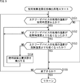
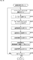
- This warning process is a notification information for detecting a predetermined event to be warned based on a temporal change in the temperature (or temperature distribution) of the sensing region obtained as a result of sensing by the thermosensor 125A and notifying the event. Is generated and output.
- step S101 the image sensor 171 of the endoscope 121 captures an image within the field of view of the endoscope 121 (that is, the imaging region 162). More specifically, the light source device 112 emits light (illumination light) emitted from the endoscope 121 and supplies the light to the endoscope 121. Thereby, light is irradiated from the endoscope 121 toward the imaging angle of view (subject). In this state, the CCU 111 controls the image sensor 171 to perform imaging. The image sensor 171 supplies captured image data to the CCU 111.
- step S102 the thermosensor 125A performs sensing and obtains information on the temperature (temperature distribution) of the sensing region.
- the thermosensor 125A supplies the sensing result to the temperature image generation unit 181.
- step S103 the temperature image generation unit 181 generates a temperature image of the sensing region based on the sensing result of the thermosensor 125A obtained by the process of step S102.
- step S104 the warning target detection unit 182 detects the warning target using the temperature image obtained by the process in step S103.
- step S105 the warning target detection unit 182 determines whether a warning target is detected. If it is determined that a warning target has been detected, the process proceeds to step S106.
- the notification information generation unit 183 generates, as notification information, warning information for performing a warning regarding the event to be warned.
- the warning information includes a warning image that is image information, a warning voice that is audio information, and the like.
- step S107 the output control unit 184 generates a display image by superimposing the warning image generated by the process of step S106 on the captured image obtained by the process of step S101 supplied from the CCU 111, and outputs the output device 114. Are displayed on the monitor 191.
- step S108 the output control unit 184 causes the warning sound generated by the process in step S106 to be output from the speaker 192 of the output device 114.
- step S109 the output control unit 184 generates a display image that displays the captured image obtained by the process of step S101 supplied from the CCU 111. And displayed on the monitor 191 of the output device 114.
- step S110 the output control unit 184 determines whether or not to end the warning process. If it is determined not to end the warning process, the process returns to step S101, and the subsequent processes are repeated. That is, while the warning process is being executed, each process from step S101 to step S110 is executed. If it is determined in step S110 that the warning process is to be terminated, the warning process is terminated.
- steps S101 to S110 are executed in parallel. That is, processing such as generation of a temperature image, detection of a warning target, generation of notification information, output of notification information, and the like is performed while performing imaging with the image sensor 171 and sensing with the thermosensor 125A.
- the warning target detection unit 182 obtains a temperature image as a moving image. Therefore, the warning target detection unit 182 detects a temporal change pattern of temperature corresponding to the event that is the warning target in the moving image.
- the event to be warned is arbitrary.
- the occurrence of bleeding may be an event to be warned.
- FIG. 5 shows an example of a temperature image.
- FIG. 5A shows an example of a temperature image at a certain time. In the case of the example of FIG. 5A, in the organ 211 located in the sensing region 163, a region 212 having a higher temperature than the surroundings is detected.
- FIG. 5B shows an example of a temperature image after a predetermined time has elapsed from the state of FIG. As shown in FIG. 5B, at this point in time, the region 212 is larger than the point in FIG. 5A. That is, as time elapses, the region 212 having a higher temperature than the surroundings expands.
- the warning target detection unit 182 determines that this region 212 is blood that has been bleeding, and detects the occurrence of bleeding.
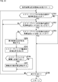
- ⁇ Bleeding detection process flow> When detecting the occurrence of bleeding, the warning target detection unit 182 performs such processing as event detection processing in step S104 of warning processing. An example of the flow of this bleeding detection process will be described with reference to the flowchart of FIG.
- the warning target detection unit 182 determines in step S131 whether or not a region having a deep body temperature higher than the surrounding temperature has occurred in the temperature image. When it is determined that an area having a temperature higher than the deep body temperature, such as the area 212 in FIG. 5A, has occurred, the process proceeds to step S132.
- step S132 the warning target detection unit 182 determines whether or not the area has expanded with time. When it is determined in the temperature image that the area is enlarged with the passage of time as in the area 212 in FIG. 5B, the process proceeds to step S133.
- step S133 the warning target detection unit 182 determines that the area is blood that has been bleeding, and detects the occurrence of bleeding.
- step S134 the warning target detection unit 182 determines whether or not to terminate the bleeding detection process. If it is determined not to end, the process returns to step S131, and the subsequent processes are repeated.
- Step S131 If it is determined in step S131 that no region having a deep body temperature higher than the surrounding temperature has occurred in the temperature image, the bleeding detection process ends, and the process returns to FIG.
- Step S132 when it is determined that the region having a temperature higher than the deep body temperature is not expanded, the warning target detection unit 182 determines that the region is not bleeding blood, and the bleeding detection process ends. Then, the process returns to FIG. If determined to end in step S134, the bleeding detection process ends, and the process returns to FIG.
- the monitoring device 113 can detect the occurrence of bleeding using the time change of temperature (temperature distribution). Therefore, the monitoring device 113 can detect more various events than when detecting the occurrence of bleeding from a simple temperature distribution (temperature distribution at a certain time). In addition, the monitoring device 113 can detect the occurrence of bleeding more accurately than the case of detecting the occurrence of bleeding from a simple temperature distribution (temperature distribution at a certain time).
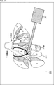
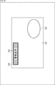
- FIG. 7 shows an example of a display image displayed on the monitor 191.
- a display image 220 illustrated in FIG. 7 illustrates an example of a display image including a warning image when the occurrence of bleeding is detected by performing the above-described bleeding detection process.
- various warning images are superimposed on the captured image 221 including the organ 211.
- a bleeding warning message image 222 that is an image for notifying the occurrence of bleeding may be displayed as a warning image.
- the bleeding warning message image 222 in FIG. 7 includes a message “with bleeding” and a number “(2)”.
- the message “with bleeding” is a message notifying the occurrence of bleeding. Thereby, the surgeon who saw the display image 220 can grasp the occurrence of bleeding more easily.
- the number “(2)” indicates the number of locations where bleeding has occurred. Therefore, an operator who has viewed the display image 220 can more easily grasp the number of places where bleeding has occurred.
- the notification information generation unit 183 may generate such a bleeding warning message image 222 as a warning image.
- the display position of the bleeding warning message image 222 is arbitrary, and may not be the upper left of the display image as in the example of FIG.
- the notification information generation unit 183 may set the display position of the bleeding warning message image 222 based on the pattern of the captured image 221.
- a bleeding position presentation image 223 that is an image showing the occurrence location is displayed as a warning image. May be.
- the bleeding position presentation image 223 in FIG. 7 is a dotted circle image.
- the bleeding occurrence location region 212 is surrounded by this dotted circle to indicate the location where the bleeding has occurred.
- the surgeon etc. who looked at the display image 220 can grasp
- the notification information generation unit 183 may generate such a bleeding position presentation image 223 as a warning image. If the sensing area of the thermosensor 125A and the imaging area of the image sensor 171 do not match, the bleeding occurrence position in the sensing area cannot be applied to the captured image 221 as it is. In such a case, the notification information generation unit 183 specifies the position of the site where bleeding has occurred in the captured image 221 based on both the captured image 221 and the temperature image. That is, the display position of the bleeding position presentation image 223 in the display image 220 is set.
- a bleeding direction presentation image 224 that is an image indicating the direction of the occurrence location may be displayed as a warning image.
- the bleeding direction presentation image 224 in FIG. 7 is an arrow image. That is, the direction of the bleeding occurrence location located outside the display image 220 is indicated by an arrow. Thereby, the surgeon who saw the display image 220 can grasp the direction in which bleeding has occurred more easily.
- the notification information generation unit 183 may generate such a bleeding direction presentation image 224 as a warning image.
- the sensing area of the thermosensor 125A and the imaging area of the image sensor 171 do not match, the bleeding occurrence position in the sensing area viewed from the captured image 221 is not specified.
- the notification information generation unit 183 identifies the positional relationship between the captured image and the temperature image based on both the captured image 221 and the temperature image, and identifies the direction of the location where bleeding has occurred in the captured image 221. . That is, the direction of the arrow of the bleeding direction presentation image 224 in the display image 220 is set.
- the display position of the bleeding direction presentation image 224 is arbitrary, and may not be the upper right of the display image as in the example of FIG.
- the display position may be determined according to the direction of the arrow, or the notification information generation unit 183 may set the display position based on the pattern of the captured image 221.
- the content of the warning image generated by the notification information generation unit 183 is arbitrary.
- the notification information generation unit 183 provides the above-described image for notifying the occurrence of bleeding, the image for notifying the number of bleeding occurrences, and the image indicating the occurrence location when the occurrence location of the bleeding is located within the captured image range. If the bleeding occurrence location is located outside the captured image range, one or more of the images indicating the direction of the occurrence location may be generated. Further, the notification information generation unit 183 may include other information in the warning image.
- the monitoring device 113 can notify the detected event using the temporal change in temperature (temperature distribution). That is, the monitoring apparatus 113 can perform notifications about more various events.
- the temperature of the surgical instrument such as the energy device 122 or the usage status (switch on / off) may also be detected and used for bleeding determination. That is, for example, the determination of bleeding may be performed only when the energy device 122 is in use or when the temperature near the tip of the energy device 122 is high.
- the monitoring device 113 can more accurately detect the occurrence of bleeding.
- weighting of the determination is performed using conditions such as the likelihood of bleeding, such as making it easy to determine bleeding. May be performed. By doing in this way, the monitoring apparatus 113 can detect the occurrence of bleeding more accurately.
- Second Embodiment> ⁇ Detection of residual heat after using the surgical tool>
- the events that can be detected by the monitoring device 113 are not limited to the above-described example.
- the monitoring device 113 may monitor the temperature (residual heat) of a surgical instrument such as the energy device 122 after use.
- the temperature near the tip of the energy device 122 changes, for example, as shown in FIG.
- a dangerous temperature which is a predetermined temperature that may affect a living body (such as an organ) when touched.
- the vicinity of the tip becomes very hot. Therefore, the vicinity of the tip of the energy device 122-2 in use is equal to or higher than a predetermined temperature (temperature in use) higher than the dangerous temperature.
- the temperature near the tip decreases, but the temperature is high for a while and care should be taken to avoid contact with a living body (such as an organ). State). That is, the temperature in the vicinity of the tip of the energy device 122-3 in the state requiring caution after use is lower than the temperature during use and equal to or higher than the dangerous temperature. Thereafter, as time elapses, the temperature near the tip of the energy device 122 further decreases, and a safe state is obtained. That is, the temperature near the tip of the energy device 122-4 after use is lower than the dangerous temperature, and returns to the same state as the energy device 122-1 before use.
- the living body When the temperature near the tip of the energy device 122 is higher than the dangerous temperature, if the vicinity of the tip of the energy device 122 is in contact with or close to a living body (such as an organ), the living body may be affected. is there. That is, in the in-use state and the cautionary state after use, the vicinity of the tip of the energy device 122 is in a high-temperature state that may affect a living body (such as an organ).
- the energy device 122-2 in use is in a state where the surgeon intends to operate it, the surgeon's attention is directed to the tip of the energy device 122 without warning. . Rather, since medical work is being performed, the display of warning images and the output of warning voices may hinder the surgeon's visual field and concentration.
- the monitoring device 113 does not give a warning during use, but only gives a warning in a state requiring attention after use.
- the warning target detection unit 182 performs a post-use caution state detection process as an event detection process in step S104 of the warning process.
- An example of the flow of the caution state detection process after use will be described with reference to the flowchart of FIG.
- the warning target detection unit 182 determines whether or not the temperature of the tip of the energy device 122 is equal to or higher than the use temperature in step S151. If it is determined that the temperature is lower than the operating temperature, since the energy device 122 is in the state before use in FIG. 8, the processing from step S152 to step S154 is omitted, and the processing proceeds to step S155.
- step S151 If it is determined in step S151 that the temperature at the tip of the energy device 122 is equal to or higher than the temperature during use, the process proceeds to step S152. In other words, the energy device 122 is in use as shown in FIG. In this state, no warning is given as described above.
- step S152 the warning target detection unit 182 determines whether or not the temperature of the tip of the energy device 122 has become lower than the operating temperature. If it is determined that the temperature at the tip of the energy device 122 is equal to or higher than the temperature during use, the energy device 122 is still in use in FIG. 8, and thus the process of step S152 is repeated.
- step S152 If it is determined in step S152 that the temperature at the tip of the energy device 122 has become lower than the operating temperature, the process proceeds to step S153. That is, the energy device 122 is in a state after the use-needed state shown in FIG.
- step S153 the warning target detection unit 182 determines whether or not the temperature of the tip of the energy device 122 has become lower than the dangerous temperature. When it is determined that the temperature at the tip of the energy device 122 is higher than the dangerous temperature, the energy device 122 is in a state of caution after use in FIG. Therefore, in step S154, the warning target detection unit 182 detects that the energy device 122 is in a state requiring caution after use as a warning target.
- the warning information is generated and the image, sound, and the like are output by the processing from step S106 to step S108 in FIG.
- step S154 when the process of step S154 is completed, the process returns to step S152, and the subsequent processes are repeated. That is, the caution state after use is detected until the temperature at the tip of the energy device 122 becomes lower than the dangerous temperature.
- step S153 If it is determined in step S153 that the temperature of the tip of the energy device 122 has become lower than the dangerous temperature, the energy device 122 is in the state after use shown in FIG. Then, the process proceeds to step S155.
- step S155 the warning target detection unit 182 determines whether to end the post-use caution state detection process. If it is determined not to end, the process returns to step S151, and the subsequent processes are repeated. That is, the energy device 122 returns to the state before use in FIG. 8, and each process described above is repeated.
- step S155 when it determines with complete
- the monitoring device 113 uses the temporal change in temperature (temperature distribution) to change the surgical instrument after use to a predetermined temperature (lower than the operating temperature). It is possible to detect that the temperature is higher than (hazardous temperature) (cautionary state after use). Therefore, the monitoring device 113 can issue a warning only for the state requiring attention after use, without warning during use of the surgical instrument. Therefore, the monitoring device 113 can perform a warning more appropriately without interfering with the operator's work. From a simple temperature distribution (temperature distribution at a certain time), it is difficult to determine whether it is in use or a state of caution after use, and thus it is difficult to perform such control.
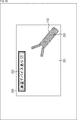
- FIG. 10 shows an example of a display image displayed on the monitor 191 in this case.
- a display image 230 illustrated in FIG. 10 illustrates an example of a display image including a warning image that is displayed only in a state requiring attention after use.
- various warning images are superimposed on a captured image 231 including an image near the tip of the energy device 122.
- the warning image indicates that there is a surgical tool in a state requiring attention after use (that is, there is a post-use surgical tool in a state of a predetermined temperature or higher).
- a residual heat warning message image 232 that is an image for notifying the user may be displayed.
- the residual heat warning message image 232 in FIG. 10 includes a message “There is a high temperature device” and a number “(2)”.
- the message “With high-temperature device” is a message notifying that there is a surgical instrument in a state requiring attention after use. Thereby, the surgeon who has seen the display image 230 can more easily grasp that there is a surgical instrument in a state requiring attention after use.
- the number “(2)” indicates the number of surgical tools that are in a state of caution after use. Therefore, the surgeon who sees the display image 230 can more easily grasp how many surgical tools are in a state of caution after use.
- the notification information generation unit 183 may generate such a residual heat warning message image 232 as a warning image.
- the display position of this residual heat warning message image 232 is arbitrary, and may not be the upper left of the display image as in the example of FIG.
- the notification information generation unit 183 may set the display position of the residual heat warning message image 232 based on the pattern of the captured image 231.
- the surgical instrument (energy device 122) is shown as a warning image.
- the remaining heat warning image 233 may be displayed.
- the residual heat warning image 233 includes, for example, a temperature image near the tip of the surgical instrument (energy device 122). That is, the temperature image near the distal end of the surgical instrument in the state requiring caution after use is displayed superimposed on the same portion of the captured image 231 (near the distal end of the surgical instrument in the state requiring caution after use).
- the surgeon or the like who has viewed the display image 230 intuitively knows which surgical instrument is at what temperature (at least the surgical instrument in a state requiring caution after use is a temperature to which attention should be paid). I can grasp it.
- the notification information generation unit 183 can easily obtain the vicinity of the tip of the energy device 122 from the temperature difference from the surroundings in the temperature image.
- the notification information generation unit 183 can easily obtain the vicinity of the tip of the energy device 122 from the characteristic (picture) of the image in the captured image 231.
- the notification information generation part 183 can obtain
- the residual heat warning image 233 a predetermined image for highlighting the surgical instrument may be superimposed instead of the temperature image. If the sensing area of the thermosensor 125A does not match the imaging area of the image sensor 171, the position of the surgical tool in the sensing area cannot be applied to the captured image 231 as it is. In such a case, the notification information generation unit 183 specifies the position of the surgical tool in the captured image 221 based on both the captured image 231 and the temperature image. That is, the display position of the residual heat warning image 233 in the display image 230 is set.
- an image indicating the direction of the surgical instrument may be displayed as a warning image.
- the direction of the surgical instrument may be indicated by an arrow.
- the notification information generation unit 183 may specify the direction near the distal end of the surgical instrument that is in a state requiring attention after use based on both the captured image 221 and the temperature image.
- the notification information generation unit 183 provides, as a warning image, the above-described image for notifying that there is a used surgical tool in a state of a predetermined temperature or higher, an image for notifying the number of surgical tools, and the surgical tool.
- a warning image the above-described image for notifying that there is a used surgical tool in a state of a predetermined temperature or higher
- an image for notifying the number of surgical tools and the surgical tool.
- One or more of an image indicating the surgical tool when positioned within the captured image range and an image indicating the direction of the surgical tool when the surgical tool is positioned outside the captured image range may be generated.
- the notification information generation unit 183 may include other information in the warning image.
- the monitoring device 113 can notify the detected event using the temporal change in temperature (temperature distribution). That is, the monitoring apparatus 113 can perform notifications about more various events.
- the operating state of the surgical instrument such as the energy device 122 may be detected from the on / off state of the switch of the energy device 122 or the like. By doing in this way, the operation state of the energy device 122 can be detected more accurately, and the monitoring device 113 can detect the state requiring attention after use more accurately.
- a device such as an LED may be provided in the handle of the energy device 122 and light may be emitted so that the warning about the remaining heat as described above may be performed. Further, such a warning may be used in combination with the warning by the display image 230 described above. By doing in this way, a warning can be more reliably given to an operator or the like.
- the monitoring device 113 can also issue a warning for events other than those described above in the same manner as the warning processing described above.
- the warning target detection unit 182 of the monitoring device 113 detects the result of hemostasis (success or failure) as an event based on a temporal change in the temperature image such as a decrease in the temperature of the bleeding region or an increase in the temperature of the blood vessel portion. It may be. Then, the notification information generation unit 183 generates, as a warning image, an image that notifies the hemostasis result or an image that notifies the number of locations where hemostasis has been performed, and the output control unit 184 captures the warning image as a captured image. And may be displayed on the monitor 191 in a superimposed manner.
- the notification information generation unit 183 when hemostasis is performed within the range of the captured image, the notification information generation unit 183 generates an image indicating the location where the hemostasis has been performed as a warning image, and the output control unit 184 captures the warning image. You may make it display on the monitor 191 superimposed on an image. Further, when the hemostasis is performed outside the range of the captured image, the notification information generation unit 183 generates an image indicating the direction in which the hemostasis is performed as a warning image, and the output control unit 184 captures the warning image. You may make it display on the monitor 191 superimposed on an image.
- the notification information generation unit 183 uses the above-described image for notifying the hemostasis result, the image for notifying the number of places where the hemostasis has been performed, and the hemostasis when the hemostasis is performed within the range of the captured image as the warning image.
- One or more of an image showing a place where the hemostasis is performed and an image showing the direction in which the hemostasis is performed when the hemostasis is performed outside the range of the captured image may be generated. Further, the notification information generation unit 183 may include other information in the warning image.
- the warning target detection unit 182 of the monitoring device 113 may perform the above-described contact with a surgical tool (such as the energy device 122) when not in use, based on a time change such as a temperature rise of a living body due to inflammation or the like in a temperature image.
- a damaged part of a living body may be detected as an event.
- the notification information generation unit 183 generates, as a warning image, an image that notifies the occurrence of the damaged portion or an image that notifies the number of damaged portions, and the output control unit 184 superimposes the warning image on the captured image. Then, it may be displayed on the monitor 191.
- the notification information generation unit 183 when the damaged part is located within the range of the captured image, the notification information generation unit 183 generates an image indicating the damaged part as a warning image, and the output control unit 184 superimposes the warning image on the captured image. May be displayed on the monitor 191. Further, when the damaged part is located outside the range of the captured image, the notification information generation unit 183 generates an image indicating the direction of the damaged part as a warning image, and the output control unit 184 displays the warning image as the captured image. And may be displayed on the monitor 191 in a superimposed manner.
- the notification information generation unit 183 uses the above-described image for notifying the occurrence of the damaged portion, the image for notifying the number of the damaged portions, and the damaged portion when the damaged portion is located within the range of the captured image as the warning image. If the image to be shown and the damaged part are located outside the range of the captured image, one or more of the images showing the direction of the damaged part may be generated. Further, the notification information generation unit 183 may include other information in the warning image.
- the warning target detection unit 182 of the monitoring device 113 uses the surgical tool based on the temporal change such as a temperature rise around the contact portion of the surgical tool (such as the energy device 122) in the temperature image. Alternatively, it may be detected as an event that the periphery of the surgical site is in a state of a predetermined temperature or higher. Then, the notification information generation unit 183 displays, as a warning image, an image that notifies that a location that is in a state of the predetermined temperature or higher has occurred, or an image that notifies the number of locations that are in a state of the predetermined temperature or higher. Then, the output control unit 184 may display the warning image on the monitor 191 in a superimposed manner with the captured image.
- the temporal change such as a temperature rise around the contact portion of the surgical tool (such as the energy device 122) in the temperature image.
- the notification information generation unit 183 displays, as a warning image, an image that notifies that a location that is in a state of the predetermined temperature or higher
- the notification information generation unit 183 uses the image indicating the occurrence position of the location where the temperature is higher than the predetermined temperature as a warning image. Then, the output control unit 184 may display the warning image on the monitor 191 in a superimposed manner with the captured image. Further, when a location that is in a state of a predetermined temperature or higher is located outside the range of the captured image, the notification information generation unit 183 uses an image that indicates the direction of occurrence of the location in a state of the predetermined temperature or higher as a warning image. Then, the output control unit 184 may display the warning image on the monitor 191 in a superimposed manner with the captured image.
- FIG. 11 shows an example of the display image.
- various warning images are superimposed on a captured image 241 including an image near the tip of the energy device 122.
- a biological temperature abnormality warning message image 242 that is an image for notifying a biological temperature abnormality may be displayed as a warning image.
- the biological temperature abnormality warning message image 242 in FIG. 11 includes a message “with heat diffusion”.
- the message “with heat diffusion” is a message notifying that a temperature abnormality of the living body has occurred. Thereby, an operator who has viewed the display image 240 can more easily grasp that a temperature abnormality of the living body has occurred.
- the biological temperature abnormality warning message image 242 may include a number indicating the number of biological temperature abnormalities. By doing in this way, the surgeon who looked at the display image 240 can grasp
- the notification information generation unit 183 may generate such a biological temperature abnormality warning message image 242 as a warning image.
- the display position of the biological temperature abnormality warning message image 242 is arbitrary, and may not be the upper left of the display image as in the example of FIG.
- the notification information generation unit 183 may set the display position of the biological temperature abnormality warning message image 242 based on the pattern of the captured image 241.
- a biological temperature abnormality warning image 243 is displayed as an image indicating a location where the temperature abnormality has occurred as a warning image. It may be displayed. For example, a dangerous region approaching 42 ° C. of a living body may be highlighted with a color or a pattern as shown in the biological temperature abnormality warning image 243. Thereby, the surgeon who saw the display image 240 can intuitively know where the temperature abnormality occurred.
- the notification information generation unit 183 provides, as a warning image, an image for notifying that the above-described location at a predetermined temperature or higher has occurred, an image for notifying the number of locations at a predetermined temperature or higher, a predetermined image When a location at a temperature or higher is located within the range of the captured image, an image showing the occurrence position of a location at or above the predetermined temperature, and a location at or above the predetermined temperature is the range of the captured image When located outside, one or more of the images indicating the direction of occurrence of a location at a temperature equal to or higher than the predetermined temperature may be generated. Further, the notification information generation unit 183 may include other information in the warning image.
- the monitoring device 113 can detect more various events based on the time change of temperature (temperature distribution), and can further notify the various events.
- the monitoring device 113 may detect an event using information other than the temperature image.
- the depth may be detected using a stereo image obtained by using a stereo image sensor, and a state in which the surgical instrument and the living body are likely to contact may be detected as an event.
- FIG. 12 is a block diagram illustrating a main configuration example of the monitoring device 113 and the like in this case.
- the endoscopic surgery support system 100 basically has the same configuration as that of FIG.
- the endoscopic surgery support system 100 includes a stereo image sensor 125B as the monitoring sensor 125 in addition to the thermosensor 125A.
- the monitoring device 113 includes a warning target detection unit 251 instead of the warning target detection unit 182.
- the stereo image sensor 125B includes a plurality of image sensors, and generates a stereo image that is a plurality of captured images having parallax with each other by capturing an image of a subject.
- the stereo image sensor 125B uses a region substantially similar to the sensing region of the thermosensor 125A as a sensing region.
- the stereo image sensor 125B is installed in a state where it is inserted into the living body of the patient 151 as shown in FIG. 1, and senses the sensing region 163 (surgical site and the vicinity of the surgical site) in FIG. 2 as with the thermosensor 125A. .
- the stereo image sensor 125B supplies the generated stereo image to the warning target detection unit 251.
- the warning target detection unit 251 acquires a temperature image from the temperature image generation unit 181.
- the warning target detection unit 251 detects an event in the living body that is a warning target, using the temperature image (temporal change in temperature (temperature distribution)) and the stereo image acquired from the stereo image sensor 125B.
- the warning target detection unit 251 can also obtain a captured image of the image sensor 171 via the CCU 111, and the captured image can also be used for detection of an event in a living body that is a warning target.
- the warning target detection unit 251 notifies the detected information to the notification information generation unit 183 as in the case of the warning target detection unit 182.
- step S171 and step S172 are performed similarly to each process of step S101 and step S102 of FIG.
- step S173 the stereo image sensor 125B performs sensing and generates a stereo image.
- the stereo image sensor 125B supplies the sensing result (stereo image) to the warning target detection unit 251.
- step S174 the temperature image generation unit 181 generates a temperature image of the sensing region based on the sensing result of the thermosensor 125A obtained by the process of step S172, as in the case of step S103 of FIG.
- step S175 the warning target detection unit 251 detects an event to be a warning target using the temperature image obtained by the process of step S174 and the stereo image obtained by the process of step S173.
- step S176 to step S181 is executed in the same manner as each process from step S105 to step S110 in FIG.
- steps S171 to S181 are executed in parallel. That is, processing such as generation of a temperature image, detection of a warning target, generation of notification information, output of notification information, and the like is performed while imaging by the image sensor 171 and sensing by the thermosensor 125A and the stereo image sensor 125B.
- the warning target detection unit 251 obtains a temperature image as a moving image. Therefore, the warning target detection unit 251 detects a temporal change pattern of the temperature corresponding to the event in the living body that is the warning target in the moving image.
- or step S204 is performed similarly to each process of step S151 thru
- the warning target detection unit 251 obtains the spatial position of the surgical instrument (energy device 122) or living body (organ) using the stereo image in step S205. For example, the warning target detection unit 251 obtains the depth positions of the tool (energy device 122) and the living body (organ) from the stereo image.
- step S206 the warning target detection unit 251 determines whether or not the surgical instrument (energy device 122) is close to the living body (organ) based on the obtained spatial position.
- the warning target detection unit 251 makes the surgical instrument (energy device 122) contact the living body (organ) in step S207. It is detected as a warning target that it is in a state requiring attention, which is a likely state.
- steps S177 to S179 in FIG. 13 generates warning information not only for the state requiring attention after use but also for the state requiring attention after contact, and the image and Audio etc. are output.
- step S207 when the process of step S207 is completed, the process returns to step S202, and the subsequent processes are repeated.
- step S206 If it is determined in step S206 that the surgical instrument (energy device 122) is not close to the living body (organ), the process in step S207 is omitted, the process returns to step S202, and the subsequent processes are performed. Repeated. In other words, in this case, it is not a contact-sensitive state.
- the warning information is generated and the image, the sound, and the like are output only for the caution state after use by the processing in steps S177 to S179 in FIG.
- step S208 is executed in the same manner as the process of step S155 of FIG.
- the monitoring device 113 can issue a warning about the state of residual heat after using the surgical instrument by using the time change of the temperature (temperature distribution). Furthermore, the monitoring device 113 can warn about the possibility of contact between the surgical instrument and the living body based on the stereo image.
- a warning about contact between the surgical instrument and the living body is given only in the case of a cautionary state after use that may damage the living body when the surgical instrument and the living body come into contact with each other. It can be carried out. In other words, it is possible to suppress the visibility and concentration of an operator or the like from being disturbed by suppressing notification of unnecessary warnings and performing warnings only when more appropriate.
- the monitoring device 113 may perform a process other than a warning on an in-vivo event detected from a temperature image or the like.
- the detected event in the living body may be evaluated to diagnose the living body.
- a change in the state of the living body may be detected as an event in the living body, and a diagnostic image for notifying a diagnosis result based on the state change may be generated.
- the monitoring device 113 performs a stimulus (that is, heating) that causes a temperature change on the living body, and detects an event in the living body as a diagnosis result based on a temporal change in temperature (temperature distribution) thereafter. Then, diagnosis information regarding the event (diagnosis result) may be output. That is, the living body may be heated by the heating unit, and a change in the state of the living body after the heating may be detected.
- a stimulus that is, heating
- diagnosis information regarding the event diagnosis result
- diagnosis information regarding the event diagnosis result
- the living body may be heated by the heating unit, and a change in the state of the living body after the heating may be detected.
- FIG. 15 is a block diagram illustrating a main configuration example of the monitoring device 113 and the like in this case.
- the endoscopic surgery support system 100 basically has the same configuration as that of FIG. However, in the case of FIG. 15, the endoscopic surgery support system 100 further includes a heater 261.
- the monitoring device 113 includes a heating control unit 271 and includes a diagnosis unit 272 instead of the warning target detection unit 182 of FIG.
- the heater 261 is a heating unit that generates heat at a predetermined temperature.
- the heater 261 is operated by an operator or the like to apply (heat) the generated heat to the living body.
- the thermosensor 125 ⁇ / b> A senses a progress (temperature change over time) after the heating of a sensing region including a portion of the living body heated by the heater 261.
- the heating control unit 271 controls the temperature of heat generated by the heater 261. In addition, the heating control unit 271 supplies information regarding the heating to the diagnosis unit 272.
- the diagnosis unit 272 diagnoses a living body or the like based on the temperature image supplied from the temperature image generation unit 181. In addition, the diagnosis unit 272 confirms the heating status and the like based on information from the heating control unit 271. The diagnosis unit 272 supplies the diagnosis result to the notification information generation unit 183.
- ⁇ Identification of sub-area> Using such an endoscopic surgery support system 100, for example, a sub-section of the liver can be detected and the area can be displayed.
- the liver is divided into a “left lobe” and a “right lobe” based on the portal blood flow, and the left lobe is further divided into an “outer area” and an “inner area”. Is divided into “front area” and “rear area”. These four areas are further divided into two areas, and eight “sub-areas” are defined. Such functional divisions are used for excision surgery and the like. For example, “sub-region” is used as one of the units of ablation.
- each subsection is specified.
- a portal branch or a hepatic artery branch
- the heat is transferred to blood in the portal branch, and a specific sub-zone along the portal branch is Temperature rises over other sub-areas. That is, the sub-region is specified by the expansion of the region where such a temperature rise has occurred.
- the “8” sub-area formed along the portal vein is more than the other sub-areas. Temperature rises. However, since the other sub-regions are formed along other portal branches, this temperature rise is difficult to spread to other sub-regions. Therefore, in the temperature image, a change in the temperature increase region is observed, and when the expansion of the temperature increase region becomes dull, the region in which the temperature has increased is specified as a sub-region of “8”. By changing the heated portal branch, the range of other sub-regions can be specified as well. That is, each sub-region can be identified.
- ⁇ Diagnosis process flow> the endoscopic surgery support system 100 executes a diagnosis process instead of the warning process.
- An example of the flow of this diagnostic process will be described with reference to the flowchart of FIG.
- the image sensor 171 images the imaging region 162 in step S221.
- the heating control unit 271 controls the heater 261 to heat a predetermined part of the living body at a temperature that is harmless to the living body.
- the thermosensor 125A performs sensing in the sensing area.
- step S224 the temperature image generation unit 181 generates a temperature image using the sensing result of the thermosensor 125A.
- the diagnosis unit 272 diagnoses the temporal change in temperature using the temperature image.
- the notification information generation unit 183 generates diagnosis information indicating the diagnosis result as notification information.
- the diagnostic information includes, for example, a diagnostic image that is an image indicating a diagnostic result, a diagnostic voice that indicates the diagnostic result by voice, and the like.
- step S227 the output control unit 184 causes the diagnostic image generated in step S226 to be superimposed on the captured image of the living body (surgical unit) generated in step S221 and displayed on the monitor 191.
- step S229 the output control unit 184 determines whether or not to end the diagnostic process. If it is determined not to end the diagnosis process, the process returns to step S221, and the subsequent processes are repeated. That is, while the diagnosis process is being executed, each process of step S221 to step S229 is executed. If it is determined in step S229 that the diagnostic process is to be terminated, the diagnostic process is terminated.
- steps S221 to S229 are executed in parallel. That is, processing such as temperature image generation, temperature change diagnosis, notification information generation, and notification information output is performed while performing heating using the heater 261, imaging by the image sensor 171 and sensing by the thermosensor 125A.
- the diagnosis unit 272 detects a temporal change pattern of the temperature corresponding to the event to be diagnosed in the moving image.
- ⁇ Display image> For example, in the case of the above-described sub-region, the diagnosis unit 272 observes the expansion of the temperature increase region in the temperature image, and when the expansion becomes dull, the temperature increase region is changed to the heated portal vein branch. Identify as corresponding sub-region. By changing the heating position, each sub-area can be identified in the same way.
- the notification information generation part 183 produces
- FIG. 19 is a diagram showing an example of a display image for displaying the diagnostic image.
- a display image 290 illustrated in FIG. 19 illustrates an example of a display image including a diagnostic image when the above-described diagnostic processing is performed to diagnose the expansion of the temperature increase region.
- a sub-region identification image 292-1 to a sub-region identification image 292- showing the position of each sub-region on the captured image 291 of the living body (surgical site) including the liver. 8 is superimposed.
- the sub-region identification image 292-1 to the sub-region identification image 292-8 are referred to as sub-region identification images 292 when it is not necessary to distinguish them from each other.
- the monitoring device 113 can make the operator more easily perform subsection excision and the like.
- the present technology may be used for detecting a lung lesion.
- a method has been used in which a lesion is marked with barium, a needle or the like before surgery, and the excised part is grasped by X-ray.
- this method is not non-invasive and has a heavy load on the patient (living body).
- this marking is performed with the heater 261 or a similar heat-generating object (for example, an object having a mechanism such as a portable body warmer).
- a similar heat-generating object for example, an object having a mechanism such as a portable body warmer.
- the present technology may be used for blood vessel detection.
- cold physiological saline / glucose may be administered, and the temperature change event of the blood vessel may be detected from the temperature image.
- cold physiological saline or the like may be administered to the lymphatic vessel, and a temperature change event of the lymphatic vessel may be detected.
- the living body may be heated by a heater 261 or the like, and an event of a difference in cooling due to a difference in the thermal conductivity may be detected from the temperature image.
- the heating described above includes both heating at a temperature higher than the body temperature of the living body and heating at a temperature lower than the body temperature (whichever may be used).
- the state of temperature change includes both a state of temperature rise and a state of temperature decrease (whichever is acceptable).
- the diagnosis may be performed by selecting from a plurality of diagnosis candidates.
- the diagnosis unit 272 performs detection of a sub-region of the liver, detection of a lesion, detection of blood vessels, detection of lymphatic vessels, identification of bones and nerves, or detection of cancer cells, and a notification information generation unit detects a diagnosis image
- an image may be generated that is displayed in a superimposed manner on a captured image of a living body and that is identifiable from sub-regions, lesions, blood vessels, lymphatic vessels, bones, nerves, or cancer cells detected by the detection unit. Good.
- the monitoring device 113 may perform not only notification of information such as a warning but also device control such as a surgical instrument based on an in vivo event detected from a temperature image or the like.
- the temperature of the gas supplied into the living body or the brightness of the illumination light irradiated into the living body may be controlled based on the temperature image measured in the living body.
- FIG. 20 is a block diagram illustrating a main configuration example of the monitoring device 113 and the like in this case. Also in this case, the endoscopic surgery support system 100 basically has the same configuration as that of FIG. However, in the case of FIG. 20, the monitoring device 113 includes a control unit 312, and further includes a warning control target detection unit 311 instead of the warning target detection unit 182 of FIG. 3.
- the warning control target detection unit 311 detects a warning and an event subject to device control based on the temperature image supplied from the temperature image generation unit 181. When an event subject to device control is detected, the warning control target detection unit 311 notifies the control unit 312 to that effect. Further, when an event to be warned is detected, the warning control target detection unit 311 supplies the notification information generation unit 183 to that effect.
- control unit 312 When the control unit 312 is notified by the warning control target detection unit 311 that an event subject to device control has been detected, the control unit 312 performs an operation on the surgical tool and the like via the surgical tool control device 115 and the pneumoperitoneum device 116. Control according to the event.
- step S244 the warning control target detection unit 311 detects the warning control target using the temperature image generated in step S243.
- step S245 the warning control target detection unit 311 determines whether a warning control target is detected.
- step S246 the control unit 312 controls the device according to the detected event.
- step S247 the notification information generation unit 183 generates abnormality occurrence notification information for notifying that an abnormality has occurred as notification information.
- the output control unit 184 causes the monitor 191 to display an abnormality occurrence notification image, which is an image of the abnormality occurrence notification information, superimposed on the captured image acquired via the CCU 111.
- step S249 the output control unit 184 supplies the speaker 192 with an abnormality occurrence notification sound that is the sound of the abnormality occurrence notification information, and causes the speaker 192 to output it.
- step S245 If it is determined in step S245 that no warning control target has been detected, the output control unit 184 causes the monitor 191 to display the captured image acquired via the CCU 111 in step S250.
- step S251 the output control unit 184 determines whether or not to end the warning control process. If it is determined not to end the warning control process, the process returns to step S241, and the subsequent processes are repeated. That is, while the warning process is being executed, each process from step S241 to step S251 is executed. If it is determined in step S251 that the warning process is to be terminated, the warning process is terminated.
- steps S241 to S251 are executed in parallel. That is, processing such as generation of a temperature image, detection of a warning target, generation of notification information, device control, and output of notification information is performed while imaging by the image sensor 171 and sensing by the thermosensor 125A.
- the warning control target detection unit 311 obtains a temperature image as a moving image. Therefore, the warning control target detection unit 311 detects a temporal change pattern of the temperature corresponding to the event that is the warning control target in the moving image.
- FIG. 22 shows an example of a display image in this case displayed on the monitor 191.
- a display image 320 illustrated in FIG. 22 illustrates an example of a display image including the above-described abnormality occurrence notification image. As shown in FIG. 22, in this display image 320, an abnormality occurrence notification image is superimposed on the captured image 321.
- a warning message image 222 that is an image for notifying the occurrence of a biological abnormality may be displayed as the abnormality occurrence notification image.
- the warning object indicating the position where the abnormality has occurred is displayed as the abnormality occurrence notification image.
- the position presentation image 323 may be displayed.
- the warning control target detection unit 311 may detect a temperature generated in the living body or higher.
- a temperature region that is harmful to an organ may be detected using a temperature image.
- step S271 the warning control target detection unit 311 determines whether or not a location higher than the dangerous temperature exists. When it is determined that there is a location higher than the dangerous temperature, the warning control target detection unit 311 determines whether or not the temperature increase is due to heating in step S272. When it determines with it being based on a heating, the warning control object detection part 311 determines whether it is outside a heating area
- step S275 the warning control target detection unit 311 determines whether or not to terminate the temperature abnormality detection process. If it is determined not to end, the processing returns to step S271 and the subsequent processing is repeated. If it is determined in step S275 that the temperature abnormality detection process is to be terminated, the temperature abnormality detection process is terminated.
- control unit 312 controls the insufflation apparatus 116 to lower the temperature of the insufflation gas in step S291.
- the control unit 312 reduces the temperature in the living body by weakening the illumination based on the surgical instrument control device 115.
- the monitoring device 113 can detect more various events based on the time change of the temperature (temperature distribution), and can control the device and notify the various events. can do.
- temperature control may be performed by controlling illumination that reduces brightness, or intensified illumination instead. Further, the temperature control of the energy device (detection of a temperature rise event in the surrounding area) may be performed in the same manner.
- the monitoring device 113 can notify various events such as warning, diagnosis, control, and the like according to the event detected using the time change of temperature (temperature distribution).
- an endoscopic surgery support system has been described as an example of a medical support system to which the present technology is applied.
- the present technology is not limited to an endoscopic surgery support system, and is optional.
- the present invention can be applied to a microscopic surgery support system that supports microscopic surgery that is a laparotomy performed using a microscope.
- a microscope is used instead of an endoscope.
- This microscope also has an image sensor, and irradiates the operation part and the periphery of the operation part with light supplied from the light source device 112, similarly to the endoscope. Then, the surgical part and the periphery of the surgical part are imaged under the control of the CCU 111.
- the series of processes described above can be executed by hardware or can be executed by software.
- a program constituting the software is installed in the computer.
- the computer includes, for example, a general-purpose personal computer that can execute various functions by installing a computer incorporated in dedicated hardware and various programs.
- FIG. 25 is a block diagram illustrating an example of a hardware configuration of a computer that executes the above-described series of processes using a program.
- a CPU Central Processing Unit
- ROM Read Only Memory
- RAM Random Access Memory
- An input / output interface 910 is also connected to the bus 904.
- An input unit 911, an output unit 912, a storage unit 913, a communication unit 914, and a drive 915 are connected to the input / output interface 910.
- the input unit 911 includes, for example, a keyboard, a mouse, a microphone, a touch panel, an input terminal, and the like.
- the output unit 912 includes, for example, a display, a speaker, an output terminal, and the like.
- the storage unit 913 includes, for example, a hard disk, a RAM disk, a nonvolatile memory, and the like.
- the communication unit 914 includes a network interface, for example.
- the drive 915 drives a removable medium 921 such as a magnetic disk, an optical disk, a magneto-optical disk, or a semiconductor memory.
- the CPU 901 loads the program stored in the storage unit 913 into the RAM 903 via the input / output interface 910 and the bus 904 and executes the program, for example. Is performed.
- the RAM 903 also appropriately stores data necessary for the CPU 901 to execute various processes.
- the program executed by the computer can be recorded and applied to, for example, a removable medium 921 as a package medium or the like.
- the program can be installed in the storage unit 913 via the input / output interface 910 by attaching the removable medium 921 to the drive 915.
- This program can also be provided via a wired or wireless transmission medium such as a local area network, the Internet, or digital satellite broadcasting. In that case, the program can be received by the communication unit 914 and installed in the storage unit 913.
- a wired or wireless transmission medium such as a local area network, the Internet, or digital satellite broadcasting.
- the program can be received by the communication unit 914 and installed in the storage unit 913.
- this program can be installed in the ROM 902 or the storage unit 913 in advance.
- the program executed by the computer may be a program that is processed in time series in the order described in this specification, or in parallel or at a necessary timing such as when a call is made. It may be a program for processing.
- the step of describing the program recorded on the recording medium is not limited to the processing performed in chronological order according to the described order, but may be performed in parallel or It also includes processes that are executed individually.
- each step described above can be executed in each device described above or any device other than each device described above.
- the device that executes the process may have the functions (functional blocks and the like) necessary for executing the process described above.
- Information necessary for processing may be transmitted to the apparatus as appropriate.
- the system means a set of a plurality of components (devices, modules (parts), etc.), and it does not matter whether all the components are in the same housing. Accordingly, a plurality of devices housed in separate housings and connected via a network and a single device housing a plurality of modules in one housing are all systems. .
- the configuration described as one device (or processing unit) may be divided and configured as a plurality of devices (or processing units).
- the configurations described above as a plurality of devices (or processing units) may be combined into a single device (or processing unit).
- a configuration other than that described above may be added to the configuration of each device (or each processing unit).
- a part of the configuration of a certain device (or processing unit) may be included in the configuration of another device (or other processing unit). .
- the present technology can take a configuration of cloud computing in which one function is shared by a plurality of devices via a network and is jointly processed.
- each step described in the above flowchart can be executed by one device or can be shared by a plurality of devices.
- the plurality of processes included in the one step can be executed by being shared by a plurality of apparatuses in addition to being executed by one apparatus.
- the present technology is not limited to this, and any configuration mounted on such a device or a device constituting the system, for example, a processor as a system LSI (Large Scale Integration), a module using a plurality of processors, a plurality of It is also possible to implement as a unit using other modules, a set obtained by further adding other functions to the unit (that is, a partial configuration of the apparatus), and the like.
- a processor as a system LSI (Large Scale Integration)
- a module using a plurality of processors a plurality of It is also possible to implement as a unit using other modules, a set obtained by further adding other functions to the unit (that is, a partial configuration of the apparatus), and the like.
- the present technology can be applied to a medical support device, an endoscope device, a microscope device, a computer that controls these devices, a medical support system including a plurality of devices, or a software module thereof.
- this technique can also take the following structures.
- a detection unit that detects an event in the living body based on a temporal change in temperature of the surgical site or the vicinity of the surgical site;
- a medical support apparatus comprising: a notification information generation unit that generates notification information for performing notification according to the in-vivo event detected by the detection unit.
- the medical support device according to (1) wherein the detection unit detects an event in the living body based on a temporal change of a temperature distribution image around the surgical part or the surgical part.
- the detection unit detects a state to be warned as an event in the living body based on a time change of the temperature distribution image,
- the medical support device according to (2), wherein the notification information generation unit generates a warning image for performing a warning regarding the state.
- the medical support device wherein the notification information generation unit generates the warning image to be displayed by being superimposed on the image of the operation part or the periphery of the operation part.
- the detection unit detects the occurrence of bleeding based on the time change of the temperature distribution image,
- the notification information generation unit includes, as the warning image, an image that notifies the occurrence of bleeding, an image that notifies the number of occurrences of bleeding, and the occurrence location when the occurrence location of bleeding is located within the captured image range. When the bleeding occurrence location is located outside the captured image range, one or more of the images indicating the direction of the occurrence location are generated.
- the medical support device according to (4).
- the detection unit detects that the surgical instrument after use is in a state of a predetermined temperature or more based on a time change of the temperature distribution image
- the notification information generation unit as the warning image, an image for notifying that there is a surgical instrument in a state of the predetermined temperature or higher, an image for notifying the number of surgical instruments, and the surgical instrument being in the captured image range If the position is within, an image indicating the surgical tool, and if the surgical tool is positioned outside the captured image range, generate one or more of the images indicating the direction of the surgical tool (4) or The medical support device according to (5).
- the detection unit detects a hemostasis result based on a temporal change of the temperature distribution image
- the notification information generation unit as the warning image, an image that notifies the hemostasis result, an image that notifies the number of locations where the hemostasis has been performed, and the hemostasis when the hemostasis is performed within the captured image range
- the hemostasis is performed outside the captured image range, at least one of an image indicating the direction in which the hemostasis is performed is generated.
- the medical support device according to any one of the above.
- the detection unit Based on the time change of the temperature distribution image, the detection unit detects a damage site around the surgical site or the surgical site due to contact with a surgical tool when not in use,
- the notification information generation unit as the warning image, an image for notifying the occurrence of the damaged portion, an image for notifying the number of damaged portions, and when the damaged portion is located within the captured image range, When the image to show and the damaged part are located outside the captured image range, one or more of the images showing the direction of the damaged part are generated.
- Support device Support device.
- the detection unit detects a location where the surgical site or the surgical site surroundings due to use of a surgical tool is in a state of a predetermined temperature or more based on a time change of the temperature distribution image
- the notification information generation unit as the warning image, an image for notifying that a location in a state of the predetermined temperature or higher has occurred, an image for notifying the number of locations in the state of the predetermined temperature or higher, the predetermined image
- a location that is at or above the temperature is located within the captured image range, an image that indicates the location where the location is at or above the predetermined temperature, and a location that is at or above the predetermined temperature is The medical support device according to any one of (4) to (8), wherein when the image is located outside the captured image range, one or more of images indicating a generation direction of a portion at a temperature equal to or higher than the predetermined temperature are generated.
- the detection unit detects a change in state of the living body as an event in the living body based on a time change of the temperature distribution image, The medical support device according to any one of (2) to (9), wherein the notification information generation unit generates a diagnostic image that notifies a diagnostic result based on the state change.
- a heating unit for heating the living body is further provided, The medical support device according to (10), wherein the detection unit detects a state change of the living body after being heated by the heating unit.
- the detection unit performs detection of a subsection of the liver, detection of a lesion, detection of a blood vessel, detection of a lymphatic vessel, identification of bones and nerves, or detection of cancer cells
- the notification information generation unit is displayed as the diagnostic image superimposed on a captured image of the surgical site, and is detected by the detection unit, the sub-region, the lesion, the blood vessel, the lymph vessel, the bone
- the medical support device according to (11), wherein an image indicating that the nerve or the cancer cell is distinguishable is generated.
- the detection unit further detects an event in the living body based on a sensing result other than the temporal change of the temperature around the surgical site or the surgical site.
- the detection unit detects an event in the living body based on a temporal change in temperature of the surgical part or the vicinity of the surgical part and a stereo image of the surgical part or the vicinity of the surgical part.
- Medical support device It further comprises a temperature sensor for detecting the temperature of the surgical site or the periphery of the surgical site, The detection unit detects an event in the living body based on a temporal change in temperature of the surgical part or the vicinity of the surgical part detected by the temperature sensor.
- Medical support device Medical support device.
- the medical support device according to any one of (1) to (15), further including a display unit that displays an image of the notification information generated by the notification information generation unit.
- the medical support apparatus according to any one of (1) to (16), further including a control unit that controls a surgical instrument in accordance with an event in the living body detected by the detection unit.
- the control unit controls the temperature of the gas supplied into the living body or the brightness of the illumination light irradiated into the living body (1) to (17).
- Medical support device (19) The medical support device Detecting events in the living body based on temporal changes in temperature around the surgical site or the surgical site, A medical support method for generating notification information for performing notification according to the detected event in the living body.
- a medical support system having a temperature sensor, a medical support device, and a display device
- the temperature sensor is configured to measure a temperature at or around a surgical site
- the medical support device includes: A detection unit for detecting an event in a living body based on a temporal change in temperature around the surgical site or the surgical site measured by the temperature sensor; A notification information generation unit that generates notification information for performing notification according to the event in the living body detected by the detection unit;
- the display device is configured to display an image of the notification information generated by the notification information generation unit.
Landscapes
- Health & Medical Sciences (AREA)
- Life Sciences & Earth Sciences (AREA)
- Surgery (AREA)
- Engineering & Computer Science (AREA)
- Medical Informatics (AREA)
- Veterinary Medicine (AREA)
- Public Health (AREA)
- General Health & Medical Sciences (AREA)
- Animal Behavior & Ethology (AREA)
- Molecular Biology (AREA)
- Biomedical Technology (AREA)
- Heart & Thoracic Surgery (AREA)
- Pathology (AREA)
- Physics & Mathematics (AREA)
- Biophysics (AREA)
- Nuclear Medicine, Radiotherapy & Molecular Imaging (AREA)
- Radiology & Medical Imaging (AREA)
- Optics & Photonics (AREA)
- Cardiology (AREA)
- Physiology (AREA)
- Signal Processing (AREA)
- Gynecology & Obstetrics (AREA)
- Oral & Maxillofacial Surgery (AREA)
- Plasma & Fusion (AREA)
- Otolaryngology (AREA)
- Endoscopes (AREA)
- Measuring And Recording Apparatus For Diagnosis (AREA)
Abstract
La technologie de la présente invention concerne un dispositif et un procédé d'assistance médicale et un système d'assistance médicale qui permet des notifications pour une plus large gamme d'événements. Cette technologie détecte un événement à l'intérieur d'un corps vivant sur la base de variations de température au cours du temps dans un site chirurgical ou à proximité d'un site chirurgical, et génère des informations de notification pour effectuer une notification qui correspond à l'événement qui a été détecté dans le corps vivant. Cette technologie peut être appliquée, par exemple, à des dispositifs d'assistance médicale, des endoscopes, des microscopes, des ordinateurs pour commander ces dispositifs, ou des systèmes d'assistance médicale comprenant une pluralité de dispositifs.
Priority Applications (2)
| Application Number | Priority Date | Filing Date | Title |
|---|---|---|---|
| DE112016002762.1T DE112016002762T5 (de) | 2015-06-19 | 2016-06-03 | Medizinische Unterstützungsvorrichtung, ihr medizinisches Unterstützungssystem |
| US15/577,826 US20180160910A1 (en) | 2015-06-19 | 2016-06-03 | Medical support device, method thereof, and medical support system |
Applications Claiming Priority (2)
| Application Number | Priority Date | Filing Date | Title |
|---|---|---|---|
| JP2015124106A JP2017006337A (ja) | 2015-06-19 | 2015-06-19 | 医療支援装置および方法、並びに、医療支援システム |
| JP2015-124106 | 2015-06-19 |
Publications (1)
| Publication Number | Publication Date |
|---|---|
| WO2016203985A1 true WO2016203985A1 (fr) | 2016-12-22 |
Family
ID=57544905
Family Applications (1)
| Application Number | Title | Priority Date | Filing Date |
|---|---|---|---|
| PCT/JP2016/066544 Ceased WO2016203985A1 (fr) | 2015-06-19 | 2016-06-03 | Dispositif et procédé d'assistance médicale, et système d'assistance médicale |
Country Status (4)
| Country | Link |
|---|---|
| US (1) | US20180160910A1 (fr) |
| JP (1) | JP2017006337A (fr) |
| DE (1) | DE112016002762T5 (fr) |
| WO (1) | WO2016203985A1 (fr) |
Cited By (1)
| Publication number | Priority date | Publication date | Assignee | Title |
|---|---|---|---|---|
| WO2018207456A1 (fr) * | 2017-05-08 | 2018-11-15 | ソニー株式会社 | Système et procédé d'acquisition d'image, et dispositif et procédé de commande |
Families Citing this family (14)
| Publication number | Priority date | Publication date | Assignee | Title |
|---|---|---|---|---|
| WO2018105020A1 (fr) * | 2016-12-05 | 2018-06-14 | オリンパス株式会社 | Dispositif d'endoscope |
| US11576555B2 (en) | 2017-03-29 | 2023-02-14 | Sony Corporation | Medical imaging system, method, and computer program |
| CN112512407B (zh) | 2018-06-12 | 2025-01-10 | H.T生物成像公司 | 用于区分组织状态和类型的系统、方法和计算机产品 |
| US11559298B2 (en) * | 2018-07-16 | 2023-01-24 | Cilag Gmbh International | Surgical visualization of multiple targets |
| GB2577719B (en) | 2018-10-03 | 2023-04-26 | Cmr Surgical Ltd | Navigational aid |
| GB2577718B (en) * | 2018-10-03 | 2022-08-24 | Cmr Surgical Ltd | Feature identification |
| EP4382068A1 (fr) * | 2018-10-09 | 2024-06-12 | Ivoclar Vivadent AG | Système d'outil dentaire |
| JP7413215B2 (ja) * | 2020-09-09 | 2024-01-15 | 英敏 太田 | 消化器内視鏡 |
| JP7669691B2 (ja) * | 2020-12-25 | 2025-04-30 | 日本電気株式会社 | 情報取得支援装置、情報取得支援方法、及び、情報取得支援プログラム |
| CN112741681B (zh) * | 2020-12-31 | 2022-07-12 | 杭州堃博生物科技有限公司 | 电子装置、射频操作提示系统及存储介质 |
| US20220211276A1 (en) * | 2021-01-05 | 2022-07-07 | Quest Medical, Inc. | Thermal imaging detection |
| WO2022244105A1 (fr) * | 2021-05-18 | 2022-11-24 | リバーフィールド株式会社 | Dispositif d'affichage de détection de force, procédé d'affichage de détection de force, et programme |
| WO2023286336A1 (fr) | 2021-07-13 | 2023-01-19 | オリンパス株式会社 | Système, programme et procédé de détermination |
| CN117678981A (zh) * | 2024-01-15 | 2024-03-12 | 中国人民解放军空军军医大学 | 一种心内科防止大量出血的介入控制系统及控制方法 |
Citations (3)
| Publication number | Priority date | Publication date | Assignee | Title |
|---|---|---|---|---|
| JPH07500757A (ja) * | 1991-11-08 | 1995-01-26 | イーピー テクノロジーズ,インコーポレイテッド | 組織のインピーダンスをモニタしながら組織を切除するシステム及び方法 |
| JP2004097519A (ja) * | 2002-09-10 | 2004-04-02 | Hitachi Medical Corp | 超音波診断装置 |
| JP2013544131A (ja) * | 2010-10-25 | 2013-12-12 | メドトロニック アーディアン ルクセンブルク ソシエテ ア レスポンサビリテ リミテ | 腎ニューロモジュレーションのためのマルチ電極アレイを有するカテーテル装置ならびに関連のシステムおよび方法 |
-
2015
- 2015-06-19 JP JP2015124106A patent/JP2017006337A/ja active Pending
-
2016
- 2016-06-03 WO PCT/JP2016/066544 patent/WO2016203985A1/fr not_active Ceased
- 2016-06-03 DE DE112016002762.1T patent/DE112016002762T5/de not_active Withdrawn
- 2016-06-03 US US15/577,826 patent/US20180160910A1/en not_active Abandoned
Patent Citations (3)
| Publication number | Priority date | Publication date | Assignee | Title |
|---|---|---|---|---|
| JPH07500757A (ja) * | 1991-11-08 | 1995-01-26 | イーピー テクノロジーズ,インコーポレイテッド | 組織のインピーダンスをモニタしながら組織を切除するシステム及び方法 |
| JP2004097519A (ja) * | 2002-09-10 | 2004-04-02 | Hitachi Medical Corp | 超音波診断装置 |
| JP2013544131A (ja) * | 2010-10-25 | 2013-12-12 | メドトロニック アーディアン ルクセンブルク ソシエテ ア レスポンサビリテ リミテ | 腎ニューロモジュレーションのためのマルチ電極アレイを有するカテーテル装置ならびに関連のシステムおよび方法 |
Cited By (7)
| Publication number | Priority date | Publication date | Assignee | Title |
|---|---|---|---|---|
| WO2018207456A1 (fr) * | 2017-05-08 | 2018-11-15 | ソニー株式会社 | Système et procédé d'acquisition d'image, et dispositif et procédé de commande |
| CN110545709A (zh) * | 2017-05-08 | 2019-12-06 | 索尼公司 | 图像获取系统、图像获取方法、控制装置和控制方法 |
| JPWO2018207456A1 (ja) * | 2017-05-08 | 2020-03-12 | ソニー株式会社 | 画像取得システム、画像取得方法、制御装置および制御方法 |
| EP3610780A4 (fr) * | 2017-05-08 | 2020-04-01 | Sony Corporation | Système et procédé d'acquisition d'image, et dispositif et procédé de commande |
| US10849486B2 (en) | 2017-05-08 | 2020-12-01 | Sony Corporation | Image acquisition system, image acquisition method, control device, and control method |
| CN110545709B (zh) * | 2017-05-08 | 2022-04-26 | 索尼公司 | 图像获取系统、图像获取方法、控制装置和控制方法 |
| JP7234920B2 (ja) | 2017-05-08 | 2023-03-08 | ソニーグループ株式会社 | 画像取得システム、画像取得方法、制御装置および制御方法 |
Also Published As
| Publication number | Publication date |
|---|---|
| JP2017006337A (ja) | 2017-01-12 |
| DE112016002762T5 (de) | 2018-03-29 |
| US20180160910A1 (en) | 2018-06-14 |
Similar Documents
| Publication | Publication Date | Title |
|---|---|---|
| WO2016203985A1 (fr) | Dispositif et procédé d'assistance médicale, et système d'assistance médicale | |
| CN107427207B (zh) | 手术系统、信息处理装置和方法 | |
| EP4096532B1 (fr) | Procédé pour mettre en oeuvre des modes de fonctionnement à plusieurs niveaux dans un système chirurgical | |
| JP7166809B2 (ja) | リアルタイム3次元(3d)心臓撮像におけるガラス状態ビューのためのシステム及び方法 | |
| US10624663B1 (en) | Controlled dissection of biological tissue | |
| JP2021079117A (ja) | レーザ光凝固の最適化のためのシステム、装置、および方法 | |
| JP2023544593A (ja) | 協働的外科用ディスプレイ | |
| JP7235912B2 (ja) | 医療画像処理システム、内視鏡システム | |
| EP3841953B1 (fr) | Système de traitement d'image médicale | |
| CA3022355A1 (fr) | Systemes et procedes facilitant l'application d'une dose thermique appropriee dans des procedures d'ablation par micro-ondes | |
| WO2020036091A1 (fr) | Dispositif de traitement d'informations et procédé de traitement d'informations | |
| WO2023286337A1 (fr) | Système, programme et procédé de traitement d'informations | |
| WO2019155931A1 (fr) | Système chirurgical, dispositif de traitement d'image, et méthode de traitement d'image | |
| CN113662594B (zh) | 乳腺穿刺定位/活检方法、装置、计算机设备和存储介质 | |
| EP3666217B1 (fr) | Visualisation composite d'une partie du corps | |
| CN113925608B (zh) | 手术辅助系统以及手术辅助方法 | |
| US20250174345A1 (en) | Adaptation of data pipelines for surgical systems | |
| JP2015188559A (ja) | 医療用イメージング装置 | |
| JP2021509334A (ja) | 浮遊粒子特性に基づく調整 | |
| US20250204763A1 (en) | Medical camera system and method for capturing images and processing said images | |
| US20230360216A1 (en) | Systems and methods for detecting perfusion in surgery | |
| US20250166787A1 (en) | Visualization of an internal process of an automated operation | |
| JP2017200516A (ja) | 統合化システム |
Legal Events
| Date | Code | Title | Description |
|---|---|---|---|
| 121 | Ep: the epo has been informed by wipo that ep was designated in this application |
Ref document number: 16811460 Country of ref document: EP Kind code of ref document: A1 |
|
| WWE | Wipo information: entry into national phase |
Ref document number: 15577826 Country of ref document: US |
|
| WWE | Wipo information: entry into national phase |
Ref document number: 112016002762 Country of ref document: DE |
|
| 122 | Ep: pct application non-entry in european phase |
Ref document number: 16811460 Country of ref document: EP Kind code of ref document: A1 |