WO2016208171A1 - Dispositif de projection, système de projection et appareil d'interface - Google Patents
Dispositif de projection, système de projection et appareil d'interface Download PDFInfo
- Publication number
- WO2016208171A1 WO2016208171A1 PCT/JP2016/002931 JP2016002931W WO2016208171A1 WO 2016208171 A1 WO2016208171 A1 WO 2016208171A1 JP 2016002931 W JP2016002931 W JP 2016002931W WO 2016208171 A1 WO2016208171 A1 WO 2016208171A1
- Authority
- WO
- WIPO (PCT)
- Prior art keywords
- basic
- image
- phase distribution
- basic image
- projection
- Prior art date
- Legal status (The legal status is an assumption and is not a legal conclusion. Google has not performed a legal analysis and makes no representation as to the accuracy of the status listed.)
- Ceased
Links
Images








Classifications
-
- G—PHYSICS
- G03—PHOTOGRAPHY; CINEMATOGRAPHY; ANALOGOUS TECHNIQUES USING WAVES OTHER THAN OPTICAL WAVES; ELECTROGRAPHY; HOLOGRAPHY
- G03B—APPARATUS OR ARRANGEMENTS FOR TAKING PHOTOGRAPHS OR FOR PROJECTING OR VIEWING THEM; APPARATUS OR ARRANGEMENTS EMPLOYING ANALOGOUS TECHNIQUES USING WAVES OTHER THAN OPTICAL WAVES; ACCESSORIES THEREFOR
- G03B21/00—Projectors or projection-type viewers; Accessories therefor
- G03B21/005—Projectors using an electronic spatial light modulator but not peculiar thereto
-
- G—PHYSICS
- G03—PHOTOGRAPHY; CINEMATOGRAPHY; ANALOGOUS TECHNIQUES USING WAVES OTHER THAN OPTICAL WAVES; ELECTROGRAPHY; HOLOGRAPHY
- G03H—HOLOGRAPHIC PROCESSES OR APPARATUS
- G03H1/00—Holographic processes or apparatus using light, infrared or ultraviolet waves for obtaining holograms or for obtaining an image from them; Details peculiar thereto
- G03H1/04—Processes or apparatus for producing holograms
- G03H1/16—Processes or apparatus for producing holograms using Fourier transform
-
- G—PHYSICS
- G03—PHOTOGRAPHY; CINEMATOGRAPHY; ANALOGOUS TECHNIQUES USING WAVES OTHER THAN OPTICAL WAVES; ELECTROGRAPHY; HOLOGRAPHY
- G03H—HOLOGRAPHIC PROCESSES OR APPARATUS
- G03H1/00—Holographic processes or apparatus using light, infrared or ultraviolet waves for obtaining holograms or for obtaining an image from them; Details peculiar thereto
- G03H1/22—Processes or apparatus for obtaining an optical image from holograms
-
- G—PHYSICS
- G03—PHOTOGRAPHY; CINEMATOGRAPHY; ANALOGOUS TECHNIQUES USING WAVES OTHER THAN OPTICAL WAVES; ELECTROGRAPHY; HOLOGRAPHY
- G03H—HOLOGRAPHIC PROCESSES OR APPARATUS
- G03H1/00—Holographic processes or apparatus using light, infrared or ultraviolet waves for obtaining holograms or for obtaining an image from them; Details peculiar thereto
- G03H1/22—Processes or apparatus for obtaining an optical image from holograms
- G03H1/2202—Reconstruction geometries or arrangements
- G03H1/2205—Reconstruction geometries or arrangements using downstream optical component
-
- G—PHYSICS
- G03—PHOTOGRAPHY; CINEMATOGRAPHY; ANALOGOUS TECHNIQUES USING WAVES OTHER THAN OPTICAL WAVES; ELECTROGRAPHY; HOLOGRAPHY
- G03H—HOLOGRAPHIC PROCESSES OR APPARATUS
- G03H1/00—Holographic processes or apparatus using light, infrared or ultraviolet waves for obtaining holograms or for obtaining an image from them; Details peculiar thereto
- G03H1/22—Processes or apparatus for obtaining an optical image from holograms
- G03H1/2294—Addressing the hologram to an active spatial light modulator
-
- G—PHYSICS
- G06—COMPUTING OR CALCULATING; COUNTING
- G06F—ELECTRIC DIGITAL DATA PROCESSING
- G06F3/00—Input arrangements for transferring data to be processed into a form capable of being handled by the computer; Output arrangements for transferring data from processing unit to output unit, e.g. interface arrangements
- G06F3/01—Input arrangements or combined input and output arrangements for interaction between user and computer
- G06F3/03—Arrangements for converting the position or the displacement of a member into a coded form
- G06F3/0304—Detection arrangements using opto-electronic means
-
- G—PHYSICS
- G09—EDUCATION; CRYPTOGRAPHY; DISPLAY; ADVERTISING; SEALS
- G09G—ARRANGEMENTS OR CIRCUITS FOR CONTROL OF INDICATING DEVICES USING STATIC MEANS TO PRESENT VARIABLE INFORMATION
- G09G3/00—Control arrangements or circuits, of interest only in connection with visual indicators other than cathode-ray tubes
- G09G3/20—Control arrangements or circuits, of interest only in connection with visual indicators other than cathode-ray tubes for presentation of an assembly of a number of characters, e.g. a page, by composing the assembly by combination of individual elements arranged in a matrix no fixed position being assigned to or needed to be assigned to the individual characters or partial characters
-
- G—PHYSICS
- G09—EDUCATION; CRYPTOGRAPHY; DISPLAY; ADVERTISING; SEALS
- G09G—ARRANGEMENTS OR CIRCUITS FOR CONTROL OF INDICATING DEVICES USING STATIC MEANS TO PRESENT VARIABLE INFORMATION
- G09G5/00—Control arrangements or circuits for visual indicators common to cathode-ray tube indicators and other visual indicators
-
- H—ELECTRICITY
- H04—ELECTRIC COMMUNICATION TECHNIQUE
- H04N—PICTORIAL COMMUNICATION, e.g. TELEVISION
- H04N5/00—Details of television systems
- H04N5/74—Projection arrangements for image reproduction, e.g. using eidophor
-
- H—ELECTRICITY
- H04—ELECTRIC COMMUNICATION TECHNIQUE
- H04N—PICTORIAL COMMUNICATION, e.g. TELEVISION
- H04N9/00—Details of colour television systems
- H04N9/12—Picture reproducers
- H04N9/31—Projection devices for colour picture display, e.g. using electronic spatial light modulators [ESLM]
- H04N9/3179—Video signal processing therefor
-
- G—PHYSICS
- G03—PHOTOGRAPHY; CINEMATOGRAPHY; ANALOGOUS TECHNIQUES USING WAVES OTHER THAN OPTICAL WAVES; ELECTROGRAPHY; HOLOGRAPHY
- G03B—APPARATUS OR ARRANGEMENTS FOR TAKING PHOTOGRAPHS OR FOR PROJECTING OR VIEWING THEM; APPARATUS OR ARRANGEMENTS EMPLOYING ANALOGOUS TECHNIQUES USING WAVES OTHER THAN OPTICAL WAVES; ACCESSORIES THEREFOR
- G03B21/00—Projectors or projection-type viewers; Accessories therefor
- G03B21/14—Details
- G03B21/20—Lamp housings
- G03B21/2006—Lamp housings characterised by the light source
- G03B21/2033—LED or laser light sources
-
- G—PHYSICS
- G03—PHOTOGRAPHY; CINEMATOGRAPHY; ANALOGOUS TECHNIQUES USING WAVES OTHER THAN OPTICAL WAVES; ELECTROGRAPHY; HOLOGRAPHY
- G03H—HOLOGRAPHIC PROCESSES OR APPARATUS
- G03H1/00—Holographic processes or apparatus using light, infrared or ultraviolet waves for obtaining holograms or for obtaining an image from them; Details peculiar thereto
- G03H1/04—Processes or apparatus for producing holograms
- G03H1/08—Synthesising holograms, i.e. holograms synthesized from objects or objects from holograms
- G03H1/0808—Methods of numerical synthesis, e.g. coherent ray tracing [CRT], diffraction specific
- G03H2001/0825—Numerical processing in hologram space, e.g. combination of the CGH [computer generated hologram] with a numerical optical element
-
- G—PHYSICS
- G03—PHOTOGRAPHY; CINEMATOGRAPHY; ANALOGOUS TECHNIQUES USING WAVES OTHER THAN OPTICAL WAVES; ELECTROGRAPHY; HOLOGRAPHY
- G03H—HOLOGRAPHIC PROCESSES OR APPARATUS
- G03H1/00—Holographic processes or apparatus using light, infrared or ultraviolet waves for obtaining holograms or for obtaining an image from them; Details peculiar thereto
- G03H1/22—Processes or apparatus for obtaining an optical image from holograms
- G03H1/2202—Reconstruction geometries or arrangements
- G03H1/2205—Reconstruction geometries or arrangements using downstream optical component
- G03H2001/2213—Diffusing screen revealing the real holobject, e.g. container filed with gel to reveal the 3D holobject
- G03H2001/2215—Plane screen
- G03H2001/2218—Plane screen being perpendicular to optical axis
-
- G—PHYSICS
- G03—PHOTOGRAPHY; CINEMATOGRAPHY; ANALOGOUS TECHNIQUES USING WAVES OTHER THAN OPTICAL WAVES; ELECTROGRAPHY; HOLOGRAPHY
- G03H—HOLOGRAPHIC PROCESSES OR APPARATUS
- G03H2225/00—Active addressable light modulator
- G03H2225/30—Modulation
- G03H2225/32—Phase only
-
- G—PHYSICS
- G09—EDUCATION; CRYPTOGRAPHY; DISPLAY; ADVERTISING; SEALS
- G09G—ARRANGEMENTS OR CIRCUITS FOR CONTROL OF INDICATING DEVICES USING STATIC MEANS TO PRESENT VARIABLE INFORMATION
- G09G2340/00—Aspects of display data processing
- G09G2340/04—Changes in size, position or resolution of an image
- G09G2340/0464—Positioning
-
- G—PHYSICS
- G09—EDUCATION; CRYPTOGRAPHY; DISPLAY; ADVERTISING; SEALS
- G09G—ARRANGEMENTS OR CIRCUITS FOR CONTROL OF INDICATING DEVICES USING STATIC MEANS TO PRESENT VARIABLE INFORMATION
- G09G2340/00—Aspects of display data processing
- G09G2340/04—Changes in size, position or resolution of an image
- G09G2340/0492—Change of orientation of the displayed image, e.g. upside-down, mirrored
Definitions
- the present invention relates to a projection apparatus, a projection system, and an interface apparatus including a phase modulation type spatial modulation element.
- Non-Patent Document 1 discloses an interface device in which a projector and a camera are combined.
- phase modulation type spatial modulation element When a phase modulation type spatial modulation element is used for the projector of the interface device, the phase distribution corresponding to the display image is displayed on the display surface of the spatial modulation element.
- a desired display image By projecting the reflected light of the light irradiated on the display surface of the spatial modulation element, a desired display image can be displayed on the projection surface.
- the phase distribution displayed on the spatial modulation element is formed one by one using an arithmetic process such as an iterative Fourier transform method. Therefore, when the projection environment fluctuates or when a moving image is displayed, the calculation amount may be enormous and processing may be delayed.
- Patent Document 1 discloses a moving picture hologram display device that enables creation and reproduction display of a moving picture hologram. According to the apparatus of Patent Document 1, since it is possible to generate an interference fringe of an object after a specific time without recalculating the hologram, the hologram calculation is performed at high speed, and real-time movie hologram creation and reproduction is performed. Display is possible.
- Non-Patent Document 2 when iterative Fourier calculation is performed, a signal region that aims at convergence of the light intensity to a target pattern is set, and a range that has a degree of freedom other than the signal region is set, thereby displaying A method for improving the contrast of an image is disclosed.
- the display image on the projection image can be moved by moving the display image on the display surface of the LCOS or diffractive optical element. . Therefore, in the Fresnel region, by using the method of Patent Document 1, the interference fringes are translated or rotated for each group that moves in the same manner, and then the interference fringes of all the groups are integrated to obtain a desired value.
- the projected image can be formed.
- Non-Patent Document 2 although the contrast of the display image can be improved, there is a problem that unnecessary optical noise swept out of the signal area is displayed when the shift calculation is performed. It was.
- An object of the present invention is to provide a projection device that improves the contrast of a target image projected using a phase modulation type spatial modulation element, prevents unnecessary optical noise from being displayed, and solves the above-described problems. There is.
- the projection device of the present invention includes a light source, a display unit that displays a phase distribution of a target image, a spatial modulation element that reflects light from the light source, and an aperture frame through which reflected light from the spatial modulation element passes. It is generated by performing an iterative Fourier transform process using an amplitude distribution in which a projection means, a signal area in which a basic figure included in the target image is arranged, and a sweep area for sweeping out optical noise from the signal area are set. Control means for displaying the phase distribution on the display unit of the spatial modulation element.
- the projection system of the present invention includes a light source, a display unit that displays a phase distribution of a target image, a spatial modulation element that reflects light from the light source, and an aperture frame through which reflected light from the spatial modulation element passes. It is generated by performing an iterative Fourier transform process using an amplitude distribution in which a projection means, a signal area in which a basic figure included in the target image is arranged, and a sweep area for sweeping out optical noise from the signal area are set.
- a control device for displaying the phase distribution on the display unit of the spatial modulation element, and setting the signal area and the sweep area in the amplitude distribution of the basic image including the basic figure, and the basic figure is in any of the signal areas.
- basic image generation means for generating a phase distribution of the basic image arranged at such a position by iterative Fourier transform processing.
- An interface device of the present invention includes an imaging device that captures an operation region for performing an interface operation, a light source, a display unit that displays a phase distribution of a target image, a spatial modulation element that reflects light from the light source, and a space Amplitude distribution in which projection means having an aperture frame through which the reflected light of the modulation element passes, a signal area in which a basic figure included in the target image is arranged, and a sweep area for sweeping out optical noise from the signal area are set And a control unit that displays a phase distribution generated by performing an iterative Fourier transform process on the display unit of the spatial modulation element, and an image captured by the imaging device is acquired and included in the image A control device that recognizes the operation of the operator and controls the projection device to project the target image based on the recognized result.
- FIG. 1 is a block diagram showing a configuration of a projection apparatus 1 according to the present embodiment.
- the projection apparatus 1 includes a control unit 10, a spatial modulation element 13, and a projection unit 15.
- the control means 10 inputs information (hereinafter referred to as target image information) relating to the projection image (also referred to as target image) from a host system such as a server. Based on the input target image information, the control means 10 generates a phase distribution (hereinafter referred to as a target image phase distribution) for forming a light intensity distribution corresponding to the target image on the projection surface.
- target image information information relating to the projection image
- the control means 10 Based on the input target image information, the control means 10 generates a phase distribution (hereinafter referred to as a target image phase distribution) for forming a light intensity distribution corresponding to the target image on the projection surface.
- the control means 10 may acquire target image information input by the user.
- the target image is composed of a single basic image will be described.
- a desired image can be obtained by combining a plurality of basic images corresponding to the basic figures.
- the target image may be formed.
- the target image information includes information on the basic image that constitutes the target image.
- Basic images include basic shapes such as circles such as “ ⁇ ”, polygons such as “ ⁇ ” and “ ⁇ ”, marks such as “ ⁇ ” and “*”, and characters such as “A” and “B”. It is an image including at least one figure (hereinafter, basic figure).
- the basic graphic is not limited to the graphic shown here, and any graphic can be used.
- the control means 10 stores the phase distribution of the basic image included in the target image information input by the host system or the user.
- the phase distribution of the basic image stored by the control means 10 is generated in advance in a server or computer connected via a network such as an intranet or the Internet.
- the control means 10 extracts the phase distribution of the basic image constituting the target image based on the input target image information, and generates the phase distribution of the target image using the phase distribution of the extracted basic image.
- the control means 10 controls the spatial modulation element 13 so that a parameter that determines the difference between the phase of the laser beam irradiated on the display unit of the spatial modulation element 13 and the phase of the laser beam reflected by the display unit changes.
- the parameters that determine the difference between the phase of the laser beam irradiated on the display unit of the spatial modulation element 13 and the phase of the laser beam reflected by the display unit are parameters relating to optical characteristics such as refractive index and optical path length, for example. .
- control means 10 changes the refractive index of the display unit by controlling the voltage applied to the spatial modulation element 13.
- the laser light applied to the display unit is appropriately diffracted based on the refractive index of the display unit. That is, the phase distribution of the laser light irradiated on the spatial modulation element 13 is modulated according to the optical characteristics of the display unit.
- control of the spatial modulation element 13 by the control means 10 is not limited to that described here.
- the control means 10 stores the phase distribution of the basic image generated by the iterative Fourier transform process with the amplitude distribution of the basic image constituting the target image and the predetermined phase distribution as initial values.
- the control means 10 uses the phase distribution of the basic image stored by itself based on the basic image information included in the input target image information. Generate a distribution. Further, the control means 10 controls the phase modulation type spatial modulation element 13 based on the phase distribution of the generated target image.
- FIG. 2 is a conceptual diagram for explaining an optical configuration of the projection apparatus 1 according to the present embodiment.
- the laser light emitted from the light source 11 is converted into the laser light 110 having a uniform wavefront by the collimator lens 12, and the display unit of the spatial modulation element 13 is irradiated.
- the control means 10 controls the intensity of the laser beam output from the light source 11 according to the brightness of an image displayed on the display unit of the spatial modulation element 13.
- Spatial modulation element 13 includes a phase modulation type spatial modulation element that receives incident laser beam 110 having a uniform wavefront and modulates the phase of incident laser beam 110.
- the spatial modulation element 13 emits the modulated modulated light 130 toward the projection unit 15.
- the incident angle of the laser beam is made non-perpendicular with respect to the display unit of the spatial modulation element 13. That is, in the present embodiment, the emission axis of the laser light emitted from the light source 11 is inclined with respect to the display unit of the spatial modulation element 13. If the emission axis of the laser beam 110 is set obliquely with respect to the display portion of the spatial modulation element 13, the efficiency can be improved because the laser beam 110 can be incident on the spatial modulation element 13 without using a beam splitter.
- the spatial modulation element 13 has a display unit that displays the phase distribution.
- the display unit of the spatial modulation element 13 displays a phase distribution for forming a target image on the projection surface.
- the modulated light 130 reflected by the display unit of the spatial modulation element 13 becomes an image in which a kind of diffraction grating forms an aggregate, and the target image is formed by collecting the light diffracted by these diffraction gratings. .
- the spatial modulation element 13 is realized by an element using, for example, a ferroelectric liquid crystal, a homogeneous liquid crystal, a vertical alignment liquid crystal, or the like.
- the spatial modulation element 13 is realized by, for example, LCOS (Liquid Crystal Crystal on Silicon) or MEMS (Micro Electro Mechanical System).
- Projection means 15 is an optical system that projects modulated light 130 reflected by spatial modulation element 13 as projection light 150. As shown in FIG. 2, the projection unit 15 includes a Fourier transform lens 16, an aperture 17, and a projection lens 18. The modulated light 130 modulated by the spatial modulation element 13 is projected as projection light 150 by the projection means 15.
- the Fourier transform lens 16 is an optical lens for forming an image formed when the modulated light 130 reflected by the display unit of the spatial modulation element 13 is projected at infinity at a nearby focal position.
- the aperture 17 is an opening frame in which an opening for erasing high-order light included in the light focused by the Fourier transform lens 16 and setting an extension of a target image displayed on the non-projection surface is opened.
- the opening formed in the aperture 17 is opened smaller than the outer periphery of the zero-order component of the projected image at the position where the aperture 17 is installed. Therefore, the peripheral region of the zeroth order component and components other than the zeroth order component are blocked by the aperture 17 and are not projected onto the projection surface.
- the aperture 17 is preferably installed at the focal position of the Fourier transform lens 16. The installation position of the aperture 17 may be shifted from the focal position as long as the function of erasing high-order light can be exhibited.
- FIG. 3 is a conceptual diagram of an example of the aperture 17.
- the aperture 17 has a rectangular opening.
- the opening of the aperture 17 may have an arbitrary shape such as a circle, an ellipse, or a polygon.
- the opening part of the aperture 17 cannot be a component, it will be described with a symbol such as the opening part 171 for the sake of easy explanation.
- a non-component element such as a zero-order component region range, a target image to be projected, a basic figure, or the like may be described.
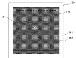
- FIGS. 4 and 5 are conceptual diagrams for explaining how the projection light 150 projected from the projection means 15 is displayed on the non-projection surface.
- a target image including a circular ( ⁇ ) basic figure 151 is projected.
- the range of the 0th-order component is indicated by a solid frame (hereinafter referred to as 0th-order region 160). Further, in FIG. 4, a range in which an image projected through the opening of the aperture 17 is displayed on the projection surface inside the zero-order region 160 is indicated by a broken line (hereinafter referred to as an opening 171). When projected through the aperture 17, higher-order components are shielded by the aperture 17, and an image within the range of the opening 171 is displayed on the projection surface. Actually, the solid line frame of the zero-order region 160 and the broken line frame of the opening 171 are not displayed on the projection surface.
- FIG. 5 is a diagram in which the inside of the zero-order area 160 is taken out.
- the modulated light 130 reflected by the display unit of the spatial modulation element 13 passes through the opening 171 through the Fourier transform lens 16, higher-order components are shielded by the aperture 17, and the image in the opening 171 in FIG. 5 is covered. Displayed on the projection surface.
- the projection lens 18 is an optical lens that magnifies and projects the light focused by the Fourier transform lens 16.
- the projection lens 18 projects the projection light 150 so that the target image corresponding to the phase distribution input to the spatial modulation element 13 is displayed on the projection surface. If the size of the target image to be projected on the projection surface is not set, the projection lens 18 may be omitted.
- the control means 10 handles the phase distribution of a basic image (hereinafter referred to as a basic image in which the sweep area is set) generated using the amplitude distribution in which the signal area and the sweep area are set.
- a basic image in which the sweep area is set a basic image in which the sweep area is set
- Non-Patent Document 2 Tatsuharu Matsushima et al., “Design of Arbitrary Shape Beam Shaping Diffraction Optical Element Using Iterative Optimization Algorithm”, Laser Research, Vol. 35, No. 5, 2007, pp 299-308).
- the signal region is a region in which it is constrained to be focused on the target image in the iterative Fourier transform process for calculating the phase distribution of the basic image.
- the sweep area is an area where optical noise is swept out by giving a degree of freedom in the iterative Fourier transform process. Referring to FIG. 5, the sweep region corresponds to a white frame portion (hereinafter, sweep region 161), and the signal region corresponds to a filled portion (hereinafter, signal region 162).
- the iterative Fourier transform process will be described in detail later.
- the sweep area may be set on four sides of the basic image as shown in FIG. 5, or may be set on two opposite sides such as the upper and lower sides or the left and right sides of the basic image, or one side of the basic image. You may provide only.
- the sweep area can be set at any location as long as it does not interfere with the projection target image.
- the shape of the sweep region may be a rectangle as shown in FIG. 5, a circle, or an arbitrary shape corresponding to the shape of the aperture opening.
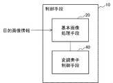
- control unit 10 includes a basic image processing unit 20 and a modulation element control unit 40.
- the basic image processing means 20 acquires the phase distribution of the basic image in which the sweep area is set from the host system, and stores the acquired phase distribution.
- the basic image processing means 20 performs a conversion process on the basic graphic on the basic image based on the target image information acquired from the host system.
- the modulation element control means 40 acquires the phase distribution generated by the basic image processing means 20, and controls the spatial modulation element 13 based on the phase distribution.
- the modulation element control means 40 changes the refractive index of the display unit of the spatial modulation element 13 by controlling the voltage applied to the spatial modulation element 13, for example.
- the basic image processing unit 20 includes a basic image storage unit 21, an image acquisition unit 23, a conversion processing unit 25, and an output unit 27.
- the basic image storage unit 21 stores the phase distribution that has been subjected to the iterative Fourier transform process in association with each basic image. As described above, the basic image storage unit 21 stores the phase distribution of the basic image in which the sweep area is set. Note that the phase distribution of the basic image is generated in a server constituting the host system.
- the basic image storage unit 21 may store the phase distribution of each basic image in association with, for example, a unique identification symbol (ID) assigned to each basic image.
- ID unique identification symbol
- the basic image storage unit 21 may be configured to include a storage area corresponding to each of a plurality of basic images. Further, for example, the basic image storage unit 21 may be configured to include a storage area that collectively stores the phase distributions of a plurality of basic images.
- the basic image storage unit 21 may store the phase distribution of the basic image including the basic graphic in correspondence with the unique identification symbol given to the basic graphic.
- the image acquisition unit 23 acquires the phase distribution of the basic image in which the sweep area is set from the host system and records it in the basic image storage unit 21. Further, the image acquisition unit 23 receives the target image information as input, and acquires a phase distribution corresponding to the basic image included in the target image information from the basic image storage unit 21.
- the target image information includes identification information for identifying a basic image included in the target image.
- the target image information includes information indicating what state the basic figure included in the basic image is on the target image.
- the state of the basic figure means a state such as a position state or a rotation state of the basic figure on the target image.
- the image acquisition unit 23 transmits the phase distribution of the basic image acquired from the basic image storage unit 21 to the conversion processing unit 25.
- the conversion processing unit 25 performs a conversion process to a basic figure based on the target image information. For example, the conversion processing unit 25 performs conversion processing such as translation processing and rotation processing on the basic figure. When the basic image itself corresponds to the target image, the conversion processing unit 25 does not have to perform conversion processing on the phase distribution of the basic image.
- the conversion processing unit 25 outputs the phase distribution of the basic image subjected to the conversion process to the output unit 27.
- FIGS. 8 and 9 use the basic image itself corresponding to the phase distribution to be converted. Yes.
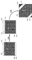
- FIG. 8 shows an example in which the conversion processing unit 25 translates the basic figure (circular shape) from the center on the target image toward the upper right corner.
- the conversion processing unit 25 performs a translational movement with respect to the basic figure (circular) in the target image by executing a calculation (translation process) by phase shift calculation on the phase distribution of the basic image including the basic figure (circular). can do.
- the phase matrix may be shifted by multiplying the phase of the basic image in the x and y directions.
- FIG. 9 shows an example in which the conversion processing unit 25 rotates the basic figure (rectangle) on the target image.
- the conversion processing unit 25 can rotate the basic figure (rectangle) on the target image by executing a calculation (rotation process) for rotating the phase distribution of the basic image including the basic figure (rectangle).
- the processes shown in FIGS. 8 and 9 can be arbitrarily combined. Note that the processing illustrated in FIGS. 8 and 9 is an example, and does not cover the processing performed by the conversion processing unit 25.
- the output unit 27 outputs the phase distribution of the target image converted by the conversion processing unit 25 to the modulation element control means 40.
- FIG. 10 is a conceptual diagram for explaining the translation process when the sweep region is not set.
- translation processing is performed on a basic graphic in a basic image including a circular ( ⁇ ) basic graphic.
- the sweep area is not set as shown in FIG. 10
- the sweep area itself does not exist even if the basic figure is translated to any position in the basic image. Therefore, unnecessary optical noise swept into the swept area is not displayed on the projection surface.
- the contrast of the displayed target image is not improved.
- FIGS. 11 to 13 are examples in which translation processing is performed on a basic image in which sweep areas are set on four sides.
- FIG. 12 is a conceptual diagram in which only the 0th order region 160 in which the 0th order component is displayed is extracted in the same example as FIG. In general translation processing, as shown in FIG. 12, when the movement amount of the basic image is large, the sweep area 161 may enter the 0th-order area 160.
- FIG. 13 is an example in which the translation process is performed on the basic figure so that the sweep region 161 does not enter the opening 171 using the method of the present embodiment.
- a translation process is performed by selecting a basic image in which the sweep region 161 does not enter the opening 171 even if the basic figure is moved to a target position.
- a plurality of phase distributions of a plurality of basic images having different basic graphic arrangement positions are prepared.
- FIG. 14 is a conceptual diagram for explaining the setting of a plurality of arrangement positions (11 to 66) in the signal area 162 in the opening 171.
- the tens place indicates the row number and the first place indicates the column number.
- the clearance gap is provided between each arrangement position, you may provide an arrangement position without a clearance gap.
- FIG. 15 is a basic image table 501 that stores the phase distribution of a basic image in which basic figures ( ⁇ ) are arranged one by one at each arrangement position in the signal area 162.
- the basic image table 501 of FIG. 15 the basic image itself is shown instead of the phase distribution so that the arrangement position of the basic figure can be easily understood.
- the basic image storage unit 21 stores the phase distribution of the basic image in which the basic figure is arranged at each arrangement position in the signal area 162.
- the conversion processing unit 25 performs a conversion process by selecting a phase distribution of the basic image close to the arrangement position of the moved basic figure.
- the image acquisition unit 23 selects, from the basic image storage unit 21, a phase distribution of a basic image in which a basic figure is arranged near a desired arrangement position based on target image information (step S11).
- the conversion processing unit 25 performs conversion processing so that the basic figure included in the selected basic image is displayed at a desired arrangement position (step S12).
- the output unit 27 outputs the converted phase distribution to the modulation element control means 40 (step S13).
- a signal area of 420 ⁇ 420 pixels is set, and a sweep area is set around the signal area. Note that a margin of 10 pixels is provided between the signal area and the sweep area.
- basic graphics are arranged without gaps in the signal area of 400 ⁇ 400 pixels, and the position of each basic graphic is set as the arrangement position.
- the phase distribution of the basic image in which one basic figure is arranged at each arrangement position is prepared for the number of arrangement positions. If the phase distribution of any basic image is selected and translation processing is performed, the basic figure can be displayed at a desired arrangement position so that the sweep region does not enter the aperture opening.
- a plurality of basic figures that can be shifted are prepared in advance so that unnecessary sweep regions do not enter the aperture opening even if the shift by the phase shift calculation is performed. Then, the basic image in which the basic graphic is arranged at the arrangement position closest to the display position of the basic graphic included in the target image displayed on the projection surface is selected. Further, the basic image is shifted so that unnecessary portions do not enter the aperture opening, and the basic graphic is displayed at a desired display position.
- the direction is perpendicular to the first direction (second direction).
- the signal area may be set to fill the screen and shifted only in the second direction. By doing so, the number of basic figures to be prepared can be greatly reduced.
- the first effect that the sweep area can be set and the contrast of the image in the signal area can be improved, and the set sweep area is within the aperture opening.
- a second effect is obtained in that it can be prevented from entering.
- the first effect is that, with respect to a basic image including a basic figure, the phase distribution of the basic image with reduced optical noise is prepared for a plurality of arrangement positions by sweeping out the optical noise from the signal area to the sweep area. It is obtained by.
- the second effect is that a phase distribution of a basic image in which a basic figure is arranged near a desired arrangement position is selected, and conversion is performed so that the sweep area is located outside the aperture opening with respect to the selected phase distribution. It is obtained by processing.
- the phase distribution of the basic image included in the target image is stored in the projection device in advance, it is not necessary to perform iterative Fourier transform processing that needs to be performed at the time of projecting the target image on the projection device side. Therefore, it is possible to speed up the process of generating the phase distribution corresponding to the target image.
- the phase distribution of a basic image in which basic figures are arranged at a plurality of arrangement positions in the signal area is prepared in correspondence with the plurality of arrangement positions. Then, when moving the basic figure, select the phase distribution of the basic image with the basic figure arranged at any of the arrangement positions, and the sweep area is the aperture opening for the selected basic image phase distribution. The basic figure is moved within the signal area so as to be located outside the unit. Therefore, the sweep area does not enter the target image.
- the basic image storage unit 21 stores the phase distribution of the basic image in which the sweep area is set above and below the signal area.
- drawing is abbreviate
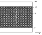
- FIG. 17 and FIG. 18 are examples in which the translation process is performed on the basic image in which the sweep area 163 is set above and below the signal area 164.
- an aperture 17-2 having a rectangular opening 172 as shown in FIG. 19 is used.
- the signal region which is a high contrast region, is set to be small in order to avoid a spot of zero-order light. Therefore, the opening 172 of the aperture 17-2 shown in FIG. 19 is smaller than the opening 171 of the aperture 17 shown in FIG.
- the entire image including higher-order components is translated on the projection surface.
- the sweep area 163 is set above and below the signal area 164, when the basic image is moved in parallel to the long side direction of the sweep area 163, even if the movement amount of the basic image is large, the zero-order area The sweep region 163 does not enter into 160.
- FIG. 20 is a conceptual diagram for explaining that a plurality of arrangement positions (1 to 7) are set in the signal region 164 in the opening 172 when the sweep region 163 is set above and below the signal region 164. It is. A one-digit number at each arrangement position indicates a line number. In FIG. 20, no gap is provided between the arrangement positions, but a gap may be provided between the arrangement positions. In the case where a gap is provided between the arrangement positions 164, the translation process is performed in a direction orthogonal to the long side direction of the sweep region 163 so that the sweep region 163 does not enter the opening 172.
- the phase distribution of the basic image in which the basic figure ( ⁇ ) is displayed at the arrangement positions 1 to 7 is stored in the basic image storage unit 21. That is, in the example of FIG. 20, it is only necessary to prepare seven phase distributions of the basic image in which the basic figure ( ⁇ ) is arranged at each arrangement position.
- the number of basic images prepared in the basic image recording unit 21 can be reduced.
- FIG. 21 shows a basic image table 502 that stores the phase distribution of a basic image in which basic figures ( ⁇ ) are arranged one by one at each arrangement position in the signal area 164.
- the basic image table 502 of FIG. 21 the basic image itself is illustrated instead of the phase distribution.
- the usage method of FIG. 21 is the same as that of the basic image table 501 of FIG.
- the arrangement position is set in a lattice pattern in the signal region 162 so that the sweep region 161 does not enter the opening 171 by the translation processing, and the movement distance in the translation processing is reduced. It is necessary to make it clear.
- the basic structure is compared with the case where the sweep area 161 is set around the signal area 162 as in the first embodiment.
- the number of phase distributions stored in the image storage unit 21 can be reduced.
- optical noise overlapping the target image can be reduced, and the contrast of the target image can be improved.
- a basic image in which basic figures are arranged by shifting the position for each pixel in the y direction may be prepared.
- the pixels of the display section of the spatial modulation element 13 are 400 ⁇ 400 pixels
- the calculation speed can be increased. Further, according to this modification, it is possible to reduce the y-direction phase shift calculation resource.
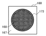
- the projection apparatus according to the present embodiment includes an aperture 17-3 in which a circular opening 173 is opened instead of the aperture 17 in which a rectangular opening 171 is opened.
- the projection apparatus according to the present embodiment has the same configuration as the control apparatus 10 according to the first embodiment except for the aperture 17-3.
- FIG. 22 shows the aperture 17-3 included in the control device according to the present embodiment.
- a circular opening 173 is opened in the aperture 17-3.
- FIG. 23 is a diagram in which the inside of the zero-order area 160 is taken out.
- the example of FIG. 23 is an example in which a square basic figure ( ⁇ ) is projected after being rotated by 45 degrees.
- FIG. 24 shows an example in which a square basic figure ( ⁇ ) is rotated 45 degrees and further translation processing is performed.
- ⁇ square basic figure
- the image acquisition unit 23 selects a basic image including a basic figure ( ⁇ ) that moves close to a desired arrangement position when rotated 45 degrees.
- the conversion processing unit 25 rotates the selected basic image ( ⁇ ) by 45 degrees and performs a translation process so that the rotated basic figure (() is arranged at a desired arrangement position.
- the output unit 27 outputs the basic image subjected to the conversion process as a target image.
- FIG. 25 is an example in which a translation process is performed on a square basic figure ( ⁇ ) with respect to a basic image set on two sides opposite to each other, and further rotated by 45 degrees. With respect to the basic image set on the two sides facing the sweep area, the rotation process can be performed on the basic figure as in the case where the sweep area is set on the four sides.
- FIG. 26 is a conceptual diagram for explaining the sweep region 167 set in the modification of the third embodiment.
- a circular signal area 168 is set, and a sweep area 167 is set around the signal area 168.
- the circular signal region 168 is set so as to include the outer periphery of the opening 173, and the sweep region 167 is set around the signal region 168.
- the sweep region 167 of this modification can be set larger than the sweep region 165 of FIG. 23, the contrast in the signal region can be further improved. Further, in this modification, as shown in FIG. 27, the arrangement positions of the basic figures may be set in a line along the radius of the signal area 168. 27, since the number of basic images to be prepared can be reduced, the storage capacity can be reduced.
- the interface device 101 includes a control device 111, an imaging device 112, and a projection device 113.
- the projection device 113 of the interface device 101 according to the present embodiment includes the functions of the projection device according to any one of the first to third embodiments. Further, at least part of the functions of the control means according to the first to third embodiments may be included in the control device 111.
- the control device 111 controls the entire interface device 101.
- the control device 111 acquires an image captured by the imaging device 112, and recognizes the position and operation of an indicator such as an operator's finger or hand included in the acquired image as an operation.
- the control device 111 provides an appropriate image signal based on the recognized result to the projection device 113 and causes the projection device 113 to project a target image.
- the control device 111 causes the imaging device 112 to capture an image of the operation region 115, reveals coordinates indicating the positional relationship between the projection image and the captured image, and performs control so that the images match each other.
- the control device 111 can be realized by the function of a microcomputer including, for example, an arithmetic device and a control device.
- control device 111 provides the projection device 113 with image information corresponding to an operation performed on the user interface displayed in the operation area 115 captured by the imaging device 112, and displays an image based on the image information.
- the projection device 113 is controlled to project.
- control device 111 when the control device 111 according to the present embodiment recognizes an operation performed on the user interface displayed in the operation area 115, the control device 111 transmits the recognized result to a host system such as a server.
- the imaging device 112 images an area including the operation area 115 for displaying a user interface.
- the imaging device 112 can be realized by, for example, a general camera function.
- the imaging device 112 may have a function capable of imaging light with a wavelength other than visible light such as infrared light or ultraviolet light. Further, the imaging device 112 may include functions such as a depth sensor and a TOF (Time of Flight) camera.
- TOF Time of Flight
- Projection device 113 includes the function of the projection device including the control means according to the first to third embodiments.
- the projection device 113 projects an image including a user interface onto an operation area 115 that receives a user operation according to the control of the control device 111.
- an interface device can be configured by combining the projection device and the camera according to each embodiment.
- the interface apparatus according to the present embodiment captures and recognizes an operation on a user interface included in a projection image by a camera and performs interactive input / output.
- the basic figure included in the projection image is often determined according to the application, and therefore it is possible to prepare a basic image including the basic figure in advance.
- FIG. 29 is a conceptual diagram showing the configuration of the projection system 100 according to the present embodiment.
- the projection system according to this embodiment includes a projection device 1 and a server 102.
- Projection apparatus 1 and server 102 are connected via network 103.
- the network 103 is a general communication line such as the Internet or an intranet.
- the server 102 transmits the phase distribution of the basic image in which the basic figure is arranged and the target image information (target image) to the projection apparatus 1.
- FIG. 30 is a block diagram showing a configuration of the server 102 of the projection system 100 according to the present embodiment.
- the server 102 includes basic image generation means 120 that generates a basic image and its phase distribution in addition to a server function 129 of a general server.
- the server function 129 functions as a communication interface for the basic image generation unit 120 to exchange data with the projection apparatus 1 or the like.
- the basic image generation unit 120 includes a basic graphic storage unit 121, a basic graphic acquisition unit 122, a basic image generation unit 123, an arrangement position change unit 124, a sweep area setting unit 125, a calculation unit 126, a basic image storage unit 127, and a phase distribution.
- An output unit 128 is included.
- the basic figure storage unit 121 stores various basic figures.
- the basic figure storage unit 121 stores basic figures such as a circle ( ⁇ ) and a rectangle ( ⁇ ).
- storage part 121 can be set arbitrarily.
- the basic figure acquisition unit 122 acquires a basic figure to be transmitted to the projection device 1 from the basic figure storage unit 121.
- the basic graphic acquisition unit 122 acquires a basic graphic specified by an operator's operation or specified by an upper system.
- the basic image generation unit 123 generates a basic image including each basic figure.
- the basic image generation unit 123 generates a basic graphic in which the size of the basic graphic displayed on the projection surface, the thickness of the line of the basic graphic, and the like are appropriate.
- the basic image generated by the basic image generation unit 123 corresponds to the electric field amplitude distribution of the target image.
- the arrangement position changing unit 124 generates a plurality of basic images in which basic figures included in the basic image generated by the basic image generation unit 123 are arranged at a plurality of arrangement positions.
- the arrangement position changing unit 124 generates a plurality of basic images in which at least one basic figure is arranged at a plurality of arrangement positions.
- the basic image generation unit 123 may include the function of the arrangement position changing unit 124.
- the sweep area setting unit 125 sets the sweep area in the basic image generated by the arrangement position changing unit 124.
- the calculation unit 126 performs an iterative Fourier transform process using the basic image in which the sweep region is set by the sweep region setting unit 125, and generates a phase distribution of the basic image including the basic figure. Details of the iterative Fourier transform process will be described later.
- the arithmetic unit 126 sets an initial value of the phase distribution used when performing the iterative Fourier transform process.
- the initial value of the phase distribution is a predetermined phase distribution and may be an arbitrary pattern.
- an arbitrary pattern such as a random pattern, a secondary lens-like pattern, or a linear pattern may be set as the initial phase distribution.
- the basic image storage unit 127 stores the phase distribution of the basic image generated by the calculation unit 126.
- the basic image storage unit 127 may store the phase distribution of the basic image in the format of the basic image table shown in FIGS.
- the phase distribution output unit 128 acquires the phase distribution of the basic image generated by the calculation unit 126 from the basic image storage unit 127, and outputs the acquired phase distribution to the server function 129 in association with the corresponding basic image.
- the phase distribution output unit 128 may output the phase distribution stored in the basic image table format shown in FIGS.
- phase distribution output from the phase distribution output unit 128 is transmitted from the server function 129 to the projection apparatus 1.
- FIG. 31 is a conceptual diagram for explaining the iterative Fourier transform process.
- each phase distribution shown in FIG. 31 is a dummy pattern, and it is possible to obtain a certain target image simply by displaying the dummy pattern on the display unit of the spatial modulation element 13 and irradiating the display unit with light.
- FT indicates Fourier transform (Fourier Transform)
- IFT indicates inverse Fourier transform (Inverse Fourier Transform).
- the amplitude distribution obtained at that stage is replaced with the amplitude distribution of the target image (basic image).
- the amplitude distribution obtained at that stage is not replaced after the Fourier transform.
- Increasing the sweep area and reducing the signal area increases the optical noise that is swept into the sweep area by increasing the degree of spatial freedom, improving the quality of the target image obtained, but darkening the image in the signal area .
- the spatial noise is reduced, so that the optical noise swept to the sweep area is reduced and the quality of the obtained target image is lowered. The image becomes brighter.
- the sweep area is preferably set so as to balance the brightness of the target image to be projected and the amount of optical noise to be removed.
- an amplitude distribution 201 (F0) of the target image and an appropriate phase distribution 211 ( ⁇ 0) are given as initial values (step S51).
- the phase distribution 211 ( ⁇ 0) given here is a predetermined phase distribution and may be an arbitrary pattern.
- the phase distribution 211 ( ⁇ 0) may be an arbitrary pattern such as a random pattern, a secondary lens-like pattern, or a linear pattern.
- Step S52 when an inverse Fourier transform operation (first inverse Fourier transform) is executed using the amplitude distribution 201 (F0) and the phase distribution 211 ( ⁇ 0), an amplitude distribution 202 (f1) and a phase distribution 212 ( ⁇ 1) are generated. (Step S52).
- the photoelectric field distribution obtained by combining the amplitude distribution of the target image and the predetermined phase distribution is inverse Fourier transformed to generate a photoelectric field distribution immediately after the spatial modulation element. Since the phase distribution 211 ( ⁇ 0) given as the initial value is a pattern unrelated to the amplitude distribution 201 (F0), the generated amplitude distribution 202 (f1) is a meaningless pattern.
- the amplitude distribution 202 (f1) is replaced with an appropriate pattern.
- uniform laser light is incident on the display unit of the spatial modulation element 13, and the amplitude distribution 202 (f1) is replaced with the uniform amplitude distribution 203 (f0) (step S53).
- Step S54 when a Fourier transform operation (first Fourier transform) is executed using the uniform amplitude distribution 203 (f0) and phase distribution 212 ( ⁇ 1), an amplitude distribution 204 (F1) and a phase distribution 213 ( ⁇ 1) are generated. (Step S54).
- the photoelectric field distribution obtained by combining the phase distribution generated by the first inverse Fourier transform and the uniform amplitude distribution is Fourier transformed to obtain the photoelectric field distribution of the target image on the projection surface.
- the amplitude distribution 204 (F1) generated first is an image in which the edge of the amplitude distribution 201 (F0) of the target image is emphasized. At this stage, the desired amplitude distribution of the target image is not yet obtained.
- step S55 When the process is continued (Yes in step S55), the amplitude distribution 204 (F1) is replaced with the amplitude distribution 201 (F0) of the target image (step S56). After step S56, the process returns to step S52.
- the phase distribution ⁇ obtained at this stage is the phase distribution of the target image. For example, it is determined what kind of condition (hereinafter referred to as a predetermined condition) the light intensity distribution
- step S55 When the process is continued (Yes in step S55), the process returns to step S52, and the inverse Fourier transform operation (second inverse Fourier transform) is executed using the amplitude distribution 201 (F0) and the phase distribution 213 ( ⁇ 1) (step S52).
- second inverse Fourier transform second inverse Fourier transform
- the photoelectric field distribution obtained by combining the phase distribution generated by the first Fourier transform and the amplitude distribution of the target image is inverse Fourier transformed to generate a photoelectric field distribution immediately after the spatial modulation element.
- the phase distribution ( ⁇ 2) obtained at this stage is used, a light intensity distribution closer to the target image can be obtained than when the phase distribution 212 ( ⁇ 1) is used.
- amplitude distribution (f2) is replaced with the uniform amplitude distribution 203 (f0) (step S53).
- a Fourier transform operation (second Fourier transform) is executed using the uniform amplitude distribution 203 (f0) and phase distribution ( ⁇ 2), an amplitude distribution (F3) and a phase distribution ( ⁇ 3) are generated (step S54). .
- the photoelectric field distribution obtained by combining the phase distribution generated by the second inverse Fourier transform and the uniform amplitude distribution is Fourier transformed to generate a photoelectric field distribution on the projection surface.
- the first and second Fourier transforms are actually the same Fourier transform process.
- step S55 when the iterative Fourier transform process is continued (Yes in step S55), the amplitude distribution (F4) is replaced with the amplitude distribution 201 (F0) of the target image (step S56), and the process returns to step S52.
- the control unit 10 performs optimization until the target phase distribution is obtained while repeating the inverse Fourier transform and the iterative Fourier transform. For example, it is only necessary to set a criterion for determining which state the amplitude distribution generated by Fourier transform is to end and a criterion for the number of iteration Fourier transforms. Further, for example, a Fourier error and an object error may be set as an error function for evaluating the degree of convergence in each iteration, and a determination to end the iteration may be made based on a determination criterion using the error function.
- an initial value is set and the inverse Fourier transform and the Fourier transform are repeatedly executed to optimize the phase distribution until a desired target image is obtained.
- the processing algorithm actually used is not limited to the above-described method, and various processes may be added or deleted.
- the phase distribution of the basic image in which the sweep area is set can be generated on the server side.
- a basic image generation unit configured in the server may be included in the projection device.
- the computer 90 in FIG. 33 is a configuration example for enabling the projection apparatus according to each embodiment, and does not limit the scope of the present invention.
- the control means according to each embodiment is preferably a microcomputer having the function of the computer 90 of FIG. 33 when included in the interface device 101 as shown in FIG.
- the computer 90 includes a processor 91, a main storage device 92, an auxiliary storage device 93, an input / output interface 95, and a communication interface 96.
- the processor 91, the main storage device 92, the auxiliary storage device 93, the input / output interface 95, and the communication interface 96 are connected to each other via a bus 99 so as to exchange data.
- the processor 91, the main storage device 92, the auxiliary storage device 93, and the input / output interface 95 are connected to a network such as the Internet or an intranet via a communication interface 96.
- the computer 90 is connected to a host system server or computer via a network, and acquires the phase distribution of the basic image and target image information from the host system.
- the processor 91 expands the program stored in the auxiliary storage device 93 or the like in the main storage device 92, and executes the expanded program.
- a configuration using a software program installed in the computer 90 may be adopted.
- the processor 91 executes arithmetic processing and control processing of the control unit according to the present embodiment.
- the main storage device 92 has an area where the program is expanded.
- the main storage device 92 may be a volatile memory such as a DRAM (Dynamic Random Access Memory). Further, a non-volatile memory such as an MRAM (Magnetic Resistive Random Access Memory) may be configured and added as the main storage device 92.
- DRAM Dynamic Random Access Memory
- MRAM Magnetic Resistive Random Access Memory
- the auxiliary storage device 93 is means for storing data such as the phase distribution of the basic image.
- the auxiliary storage device 93 is configured by a local disk such as a hard disk or a flash memory. It is possible to store the phase distribution of the basic image in the main storage device 92 and omit the auxiliary storage device 93.
- the input / output interface 95 is a device that connects the computer 90 and peripheral devices based on a connection standard.
- the communication interface 96 is an interface for connecting to a network such as the Internet or an intranet. In FIG. 33, the interface is abbreviated as I / F (Interface).
- I / F Interface
- the input / output interface 95 and the communication interface 96 may be shared as an interface connected to an external device.
- the computer 90 may be configured so that input devices such as a keyboard, a mouse, and a touch panel can be connected as necessary. These input devices are used for inputting information and settings. Note that when a touch panel is used as an input device, the display screen of the display device may be configured to also serve as an interface of the input device. Data exchange between the processor 91 and the input device may be mediated by the input interface 95.
- the communication interface 96 is connected to a host system such as another computer or server through a network.
- the host system transmits the phase distribution of the basic image used in each embodiment to the computer 90 via the communication interface 96. Further, the host system transmits target image information used in each embodiment to the computer 90 via the communication interface 96.
- the host system may generate the phase distribution of the basic image used in each embodiment by its own device or may acquire it from another device.
- the computer 90 may be provided with a display device for displaying information.
- the computer 90 is preferably provided with a display control device (not shown) for controlling the display of the display device.
- the display device may be connected to the computer 90 via the input interface 95.
- the computer 90 may be provided with a reader / writer as necessary.
- the reader / writer is connected to the bus 99 and reads a data program from the recording medium and writes a processing result of the computer 90 to the recording medium between the processor 91 and a recording medium (program recording medium) (not shown).
- the recording medium can be realized by a semiconductor recording medium such as an SD (Secure Digital) card or a USB (Universal Serial Bus) memory.
- the recording medium 516 may be realized by a magnetic recording medium such as a flexible disk, an optical recording medium such as a CD (Compact Disk) and a DVD (Digital Versatile Disk), and other recording media.
- the above is an example of the hardware configuration for enabling the control means according to the embodiment of the present invention.
- the hardware configuration in FIG. 33 is an example of a hardware configuration for enabling the projection apparatus according to the present embodiment, and does not limit the scope of the present invention.
- a processing program that causes a computer to execute processing by the projection apparatus according to the present embodiment is also included in the scope of the present invention.
- a program recording medium that records the processing program according to the embodiment of the present invention is also included in the scope of the present invention.
Landscapes
- Engineering & Computer Science (AREA)
- Physics & Mathematics (AREA)
- General Physics & Mathematics (AREA)
- Theoretical Computer Science (AREA)
- General Engineering & Computer Science (AREA)
- Signal Processing (AREA)
- Multimedia (AREA)
- Computer Hardware Design (AREA)
- Human Computer Interaction (AREA)
- Mathematical Physics (AREA)
- Projection Apparatus (AREA)
- Liquid Crystal Display Device Control (AREA)
- Transforming Electric Information Into Light Information (AREA)
- Control Of Indicators Other Than Cathode Ray Tubes (AREA)
- Controls And Circuits For Display Device (AREA)
- Optics & Photonics (AREA)
Abstract
Priority Applications (2)
| Application Number | Priority Date | Filing Date | Title |
|---|---|---|---|
| US15/735,272 US10620511B2 (en) | 2015-06-23 | 2016-06-17 | Projection device, projection system, and interface apparatus |
| JP2017524630A JP6911759B2 (ja) | 2015-06-23 | 2016-06-17 | 投射装置、投射システムおよびインターフェース装置 |
Applications Claiming Priority (2)
| Application Number | Priority Date | Filing Date | Title |
|---|---|---|---|
| JP2015125298 | 2015-06-23 | ||
| JP2015-125298 | 2015-06-23 |
Publications (1)
| Publication Number | Publication Date |
|---|---|
| WO2016208171A1 true WO2016208171A1 (fr) | 2016-12-29 |
Family
ID=57584780
Family Applications (1)
| Application Number | Title | Priority Date | Filing Date |
|---|---|---|---|
| PCT/JP2016/002931 Ceased WO2016208171A1 (fr) | 2015-06-23 | 2016-06-17 | Dispositif de projection, système de projection et appareil d'interface |
Country Status (3)
| Country | Link |
|---|---|
| US (1) | US10620511B2 (fr) |
| JP (1) | JP6911759B2 (fr) |
| WO (1) | WO2016208171A1 (fr) |
Cited By (6)
| Publication number | Priority date | Publication date | Assignee | Title |
|---|---|---|---|---|
| WO2018211878A1 (fr) * | 2017-05-19 | 2018-11-22 | ソニー株式会社 | Dispositif de génération de données de modulation de phase, appareil d'éclairage et projecteur |
| WO2020144950A1 (fr) * | 2019-01-11 | 2020-07-16 | ソニーセミコンダクタソリューションズ株式会社 | Dispositif d'affichage et procédé de réglage de dispositif d'affichage |
| WO2021117403A1 (fr) * | 2019-12-12 | 2021-06-17 | Necプラットフォームズ株式会社 | Dispositif de transmission de lumière, système de communication et procédé de transmission de lumière |
| WO2021210436A1 (fr) * | 2020-04-15 | 2021-10-21 | ソニーグループ株式会社 | Dispositif de traitement d'informations, procédé de traitement d'informations et programme de traitement d'informations |
| JPWO2021235085A1 (fr) * | 2020-05-18 | 2021-11-25 | ||
| CN114363588A (zh) * | 2020-10-13 | 2022-04-15 | 深圳光峰科技股份有限公司 | 一种高亮度云层投影成像系统 |
Families Citing this family (4)
| Publication number | Priority date | Publication date | Assignee | Title |
|---|---|---|---|---|
| CN106338905B (zh) * | 2016-10-31 | 2017-11-14 | 京东方科技集团股份有限公司 | 一种显示装置及其显示方法 |
| US11467419B2 (en) * | 2018-09-14 | 2022-10-11 | Nanchang O-Film Bio-Identification Technology Co., Ltd. | Projection module, structured light three-dimensional imaging device and electronic apparatus |
| CN116489325B (zh) * | 2023-04-11 | 2026-02-06 | 南通大学 | 一种用于提高投影仪画质的方法及装置 |
| GB2638945B (en) * | 2024-01-12 | 2026-04-01 | Vividq Ltd | Method and display system |
Citations (6)
| Publication number | Priority date | Publication date | Assignee | Title |
|---|---|---|---|---|
| JPH10222046A (ja) * | 1996-12-06 | 1998-08-21 | Nippon Telegr & Teleph Corp <Ntt> | 計算機ホログラム作成方法及びその方法を記録した記録媒体及び動画ホログラム表示装置 |
| JP2001188460A (ja) * | 1999-10-18 | 2001-07-10 | Victor Co Of Japan Ltd | 計算機ホログラム及びその作成方法 |
| JP2010521004A (ja) * | 2007-03-09 | 2010-06-17 | シーリアル テクノロジーズ ソシエテ アノニム | 補正位相符号化を備えるホログラフィック投影ディスプレイ |
| WO2013111374A1 (fr) * | 2012-01-24 | 2013-08-01 | 日本電気株式会社 | Dispositif d'interface, procédé de commande d'un dispositif d'interface, système d'interface et procédé de commande d'un système d'interface |
| JP2014511500A (ja) * | 2011-02-16 | 2014-05-15 | ケンブリッジ・エンタープライズ・リミテッド | 光ビームルーティング電気通信装置および方法 |
| JP2014206710A (ja) * | 2013-04-16 | 2014-10-30 | 東芝アルパイン・オートモティブテクノロジー株式会社 | 計算機ホログラムのデータ作成装置 |
Family Cites Families (1)
| Publication number | Priority date | Publication date | Assignee | Title |
|---|---|---|---|---|
| US9406166B2 (en) * | 2010-11-08 | 2016-08-02 | Seereal Technologies S.A. | Display device, in particular a head-mounted display, based on temporal and spatial multiplexing of hologram tiles |
-
2016
- 2016-06-17 US US15/735,272 patent/US10620511B2/en active Active
- 2016-06-17 WO PCT/JP2016/002931 patent/WO2016208171A1/fr not_active Ceased
- 2016-06-17 JP JP2017524630A patent/JP6911759B2/ja active Active
Patent Citations (6)
| Publication number | Priority date | Publication date | Assignee | Title |
|---|---|---|---|---|
| JPH10222046A (ja) * | 1996-12-06 | 1998-08-21 | Nippon Telegr & Teleph Corp <Ntt> | 計算機ホログラム作成方法及びその方法を記録した記録媒体及び動画ホログラム表示装置 |
| JP2001188460A (ja) * | 1999-10-18 | 2001-07-10 | Victor Co Of Japan Ltd | 計算機ホログラム及びその作成方法 |
| JP2010521004A (ja) * | 2007-03-09 | 2010-06-17 | シーリアル テクノロジーズ ソシエテ アノニム | 補正位相符号化を備えるホログラフィック投影ディスプレイ |
| JP2014511500A (ja) * | 2011-02-16 | 2014-05-15 | ケンブリッジ・エンタープライズ・リミテッド | 光ビームルーティング電気通信装置および方法 |
| WO2013111374A1 (fr) * | 2012-01-24 | 2013-08-01 | 日本電気株式会社 | Dispositif d'interface, procédé de commande d'un dispositif d'interface, système d'interface et procédé de commande d'un système d'interface |
| JP2014206710A (ja) * | 2013-04-16 | 2014-10-30 | 東芝アルパイン・オートモティブテクノロジー株式会社 | 計算機ホログラムのデータ作成装置 |
Cited By (15)
| Publication number | Priority date | Publication date | Assignee | Title |
|---|---|---|---|---|
| JP7196838B2 (ja) | 2017-05-19 | 2022-12-27 | ソニーグループ株式会社 | 位相変調データ生成装置、照明装置、およびプロジェクタ |
| JPWO2018211878A1 (ja) * | 2017-05-19 | 2020-03-19 | ソニー株式会社 | 位相変調データ生成装置、照明装置、およびプロジェクタ |
| US11036122B2 (en) | 2017-05-19 | 2021-06-15 | Sony Corporation | Phase modulation data generating unit, illumination unit, and projector |
| WO2018211878A1 (fr) * | 2017-05-19 | 2018-11-22 | ソニー株式会社 | Dispositif de génération de données de modulation de phase, appareil d'éclairage et projecteur |
| WO2020144950A1 (fr) * | 2019-01-11 | 2020-07-16 | ソニーセミコンダクタソリューションズ株式会社 | Dispositif d'affichage et procédé de réglage de dispositif d'affichage |
| US11676546B2 (en) | 2019-01-11 | 2023-06-13 | Sony Semiconductor Solutions Corporation | Display apparatus and method of adjusting display apparatus to display a phase distribution pattern |
| WO2021117403A1 (fr) * | 2019-12-12 | 2021-06-17 | Necプラットフォームズ株式会社 | Dispositif de transmission de lumière, système de communication et procédé de transmission de lumière |
| JP2021093663A (ja) * | 2019-12-12 | 2021-06-17 | Necプラットフォームズ株式会社 | 送光装置、通信システム、および送光方法 |
| US12063459B2 (en) | 2019-12-12 | 2024-08-13 | Nec Platforms, Ltd. | Light transmitting device, communication system, and light transmitting method |
| WO2021210436A1 (fr) * | 2020-04-15 | 2021-10-21 | ソニーグループ株式会社 | Dispositif de traitement d'informations, procédé de traitement d'informations et programme de traitement d'informations |
| US12189257B2 (en) | 2020-04-15 | 2025-01-07 | Sony Group Corporation | Information processing device and information processing method |
| JPWO2021235085A1 (fr) * | 2020-05-18 | 2021-11-25 | ||
| JP7529019B2 (ja) | 2020-05-18 | 2024-08-06 | ソニーグループ株式会社 | 照明装置、照明方法、プロジェクタ装置 |
| US12413683B2 (en) | 2020-05-18 | 2025-09-09 | Sony Group Corporation | Illumination apparatus, illumination method, and projector apparatus |
| CN114363588A (zh) * | 2020-10-13 | 2022-04-15 | 深圳光峰科技股份有限公司 | 一种高亮度云层投影成像系统 |
Also Published As
| Publication number | Publication date |
|---|---|
| US10620511B2 (en) | 2020-04-14 |
| US20180173082A1 (en) | 2018-06-21 |
| JP6911759B2 (ja) | 2021-07-28 |
| JPWO2016208171A1 (ja) | 2018-05-31 |
Similar Documents
| Publication | Publication Date | Title |
|---|---|---|
| JP6911759B2 (ja) | 投射装置、投射システムおよびインターフェース装置 | |
| JPWO2017013862A1 (ja) | 投射装置、投射方法およびプログラム記憶媒体 | |
| TWI605896B (zh) | Light modulation method, light modulation program, light modulation device, and light irradiation device | |
| US20150181091A1 (en) | Plenoptic Camera Resolution | |
| JPWO2018101097A1 (ja) | 投射装置、投射方法およびプログラム | |
| JP6763368B2 (ja) | 制御装置、制御方法及びプログラム | |
| JP2022531729A (ja) | 高密度光データ記録 | |
| WO2019009722A2 (fr) | Reconstruction de champ lumineux d'interférence à l'aide de points lumineux répartis de manière éparse | |
| JP5498024B2 (ja) | ホログラムパターン生成方法と多点集光装置 | |
| JP6920974B2 (ja) | 距離計測装置および距離計測方法 | |
| KR102188636B1 (ko) | 홀로그램 디스플레이를 위한 서브-홀로그램 생성 방법 및 장치 | |
| KR102028864B1 (ko) | 광원 위치를 보정하기 위한 현미경 장치 및 그 방법 | |
| JP6074784B2 (ja) | ホログラムデータ作成プログラム | |
| WO2021045685A1 (fr) | Conception et construction de projecteurs de points pour modules de capteurs tridimensionnels | |
| JP7097787B2 (ja) | 撮像装置および撮像方法 | |
| JP6645588B2 (ja) | 表示システム | |
| WO2022137777A1 (fr) | Dispositif et procédé de projection | |
| US11688053B2 (en) | Sensor signal visualization for sensors of coordinate measuring machines and microscopes | |
| KR102754871B1 (ko) | 3차원 홀로그래픽 이미지를 처리하는 방법 및 장치 | |
| JP4091455B2 (ja) | 3次元形状計測方法及び3次元形状計測装置並びにその処理プログラムと記録媒体 | |
| JP2013148471A (ja) | デジタルホログラフィにおける像再生方法 | |
| JP6693518B2 (ja) | 情報入力装置および照合システム | |
| CN112649966B (zh) | 一种结构光投射装置以及光学设备 | |
| JP7246543B1 (ja) | 通信装置、プログラム、及び通信方法 | |
| TWI890072B (zh) | 描繪資料之生成方法、描繪資料生成裝置、描繪資料生成程式、曝光系統及元件製造方法 |
Legal Events
| Date | Code | Title | Description |
|---|---|---|---|
| 121 | Ep: the epo has been informed by wipo that ep was designated in this application |
Ref document number: 16813943 Country of ref document: EP Kind code of ref document: A1 |
|
| ENP | Entry into the national phase |
Ref document number: 2017524630 Country of ref document: JP Kind code of ref document: A |
|
| WWE | Wipo information: entry into national phase |
Ref document number: 15735272 Country of ref document: US |
|
| NENP | Non-entry into the national phase |
Ref country code: DE |
|
| 122 | Ep: pct application non-entry in european phase |
Ref document number: 16813943 Country of ref document: EP Kind code of ref document: A1 |