WO2021117403A1 - Dispositif de transmission de lumière, système de communication et procédé de transmission de lumière - Google Patents
Dispositif de transmission de lumière, système de communication et procédé de transmission de lumière Download PDFInfo
- Publication number
- WO2021117403A1 WO2021117403A1 PCT/JP2020/041899 JP2020041899W WO2021117403A1 WO 2021117403 A1 WO2021117403 A1 WO 2021117403A1 JP 2020041899 W JP2020041899 W JP 2020041899W WO 2021117403 A1 WO2021117403 A1 WO 2021117403A1
- Authority
- WO
- WIPO (PCT)
- Prior art keywords
- light
- signal
- image
- spatial
- communication
- Prior art date
- Legal status (The legal status is an assumption and is not a legal conclusion. Google has not performed a legal analysis and makes no representation as to the accuracy of the status listed.)
- Ceased
Links
Images





Classifications
-
- H—ELECTRICITY
- H04—ELECTRIC COMMUNICATION TECHNIQUE
- H04N—PICTORIAL COMMUNICATION, e.g. TELEVISION
- H04N9/00—Details of colour television systems
- H04N9/12—Picture reproducers
- H04N9/31—Projection devices for colour picture display, e.g. using electronic spatial light modulators [ESLM]
- H04N9/3141—Constructional details thereof
- H04N9/315—Modulator illumination systems
- H04N9/3155—Modulator illumination systems for controlling the light source
-
- G—PHYSICS
- G02—OPTICS
- G02B—OPTICAL ELEMENTS, SYSTEMS OR APPARATUS
- G02B26/00—Optical devices or arrangements for the control of light using movable or deformable optical elements
- G02B26/08—Optical devices or arrangements for the control of light using movable or deformable optical elements for controlling the direction of light
-
- G—PHYSICS
- G02—OPTICS
- G02F—OPTICAL DEVICES OR ARRANGEMENTS FOR THE CONTROL OF LIGHT BY MODIFICATION OF THE OPTICAL PROPERTIES OF THE MEDIA OF THE ELEMENTS INVOLVED THEREIN; NON-LINEAR OPTICS; FREQUENCY-CHANGING OF LIGHT; OPTICAL LOGIC ELEMENTS; OPTICAL ANALOGUE/DIGITAL CONVERTERS
- G02F1/00—Devices or arrangements for the control of the intensity, colour, phase, polarisation or direction of light arriving from an independent light source, e.g. switching, gating or modulating; Non-linear optics
- G02F1/01—Devices or arrangements for the control of the intensity, colour, phase, polarisation or direction of light arriving from an independent light source, e.g. switching, gating or modulating; Non-linear optics for the control of the intensity, phase, polarisation or colour
-
- H—ELECTRICITY
- H04—ELECTRIC COMMUNICATION TECHNIQUE
- H04B—TRANSMISSION
- H04B10/00—Transmission systems employing electromagnetic waves other than radio-waves, e.g. infrared, visible or ultraviolet light, or employing corpuscular radiation, e.g. quantum communication
- H04B10/11—Arrangements specific to free-space transmission, i.e. transmission through air or vacuum
- H04B10/114—Indoor or close-range type systems
- H04B10/116—Visible light communication
-
- H—ELECTRICITY
- H04—ELECTRIC COMMUNICATION TECHNIQUE
- H04B—TRANSMISSION
- H04B10/00—Transmission systems employing electromagnetic waves other than radio-waves, e.g. infrared, visible or ultraviolet light, or employing corpuscular radiation, e.g. quantum communication
- H04B10/50—Transmitters
- H04B10/58—Compensation for non-linear transmitter output
-
- H—ELECTRICITY
- H04—ELECTRIC COMMUNICATION TECHNIQUE
- H04N—PICTORIAL COMMUNICATION, e.g. TELEVISION
- H04N9/00—Details of colour television systems
- H04N9/12—Picture reproducers
- H04N9/31—Projection devices for colour picture display, e.g. using electronic spatial light modulators [ESLM]
- H04N9/3179—Video signal processing therefor
- H04N9/3182—Colour adjustment, e.g. white balance, shading or gamut
Definitions
- the present invention relates to a light transmitting device or the like that transmits a spatial light signal.
- Patent Document 1 discloses a projection device including a phase modulation type spatial light modulation element.
- the apparatus of Patent Document 1 displays a phase image for forming an image on a display surface of a spatial light modulation element, and forms a desired image on the screen by projecting reflected light of the light emitted on the display surface.
- a projection device including a phase modulation type spatial light modulation element concentrates energy on a desired image portion by operating so as to sequentially switch a portion for projecting the projected light. Therefore, if a projection device including a phase modulation type spatial light modulation element is used, a desired image can be displayed brighter than a projection device including other types of elements if the output of the light source is the same.
- a projection device including a phase modulation type spatial light modulation element can be applied not only to image projection but also to communication using projected light as a spatial optical signal (also called spatial optical communication).
- a spatial optical signal also called spatial optical communication.
- the radio waves used for communication are transmitted in all directions, there is a possibility of being intercepted via a receiving device arranged within the transmission range of the radio waves.
- spatial optical communication unless another light receiving device is arranged between the light transmitting device and the light receiving device, the light receiving device is not intercepted.
- An image transmitted from a projection device including a general phase modulation type spatial light modulation element displays a ghost image corresponding to a desired image at a rotationally symmetric position centered on the 0th-order light. Therefore, when a projection device including a phase modulation type spatial light modulation element is applied to spatial optical communication, a ghost image corresponding to a desired spatial optical signal may be displayed in an unexpected place, which may lead to information leakage. there were.
- Patent Document 2 discloses a technique for making it difficult to visually recognize ghosts generated when projected light is projected using a phase modulation type spatial light modulation element.
- a phase image of an image including a ghost compensation image and a desired image is displayed on a display unit, and the reflected light of the light emitted to the display unit is projected to visually recognize the ghost compensation image.
- a desired image that is less likely to be formed is formed on the projected surface.
- the ghost compensation image is an image in which the portion of the display information displayed on the projection surface is bright, while the portion of the ghost image generated accompanying the display information is dark, and the overall brightness is set high.
- the visibility of the ghost image can be lowered by reducing the difference in brightness in the vicinity of the ghost image.
- the visibility of the ghost image is reduced, if the pulse pattern of the spatial optical signal is detected, the information contained in the spatial optical signal may be leaked.
- An object of the present invention is to provide a light transmission device or the like that can improve security in spatial optical communication.
- a transmitter that transmits a spatial optical signal including a communication signal and a dummy signal having the same brightness as the ghost image of the communication signal are added to the spatial optical signal to obtain a ghost image. It includes a light transmission control unit that controls the transmitter so that a dummy signal is displayed at the position.
- the computer adds a dummy signal having the same brightness as the ghost image of the communication signal to the spatial optical signal, and the dummy signal is displayed at the position of the ghost image.
- FIG. 1 is a block diagram showing an example of the configuration of the communication system 10 of the present embodiment.
- the communication system 10 includes a transmitter 11, a light transmission control unit 15, a receiver 17, and a communication control unit 19.
- the light transmitter 11 and the light transmission control unit 15 constitute a light transmission device 100.
- the light transmission control unit 15 and the communication control unit 19 constitute a control device 110.
- the transmitter 11 is connected to the light transmission control unit 15.
- the transmitter 11 is a projector including a phase modulation type spatial light modulator.
- the transmitter 11 transmits a spatial optical signal including a communication signal under the control of the light transmission control unit 15.
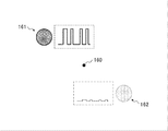
- FIG. 2 is a conceptual diagram for explaining a ghost image that can be generated on the optical path of the communication signal 161 transmitted from the transmitter 11.
- the spatial light signal transmitted from the transmitter 11 includes the 0th-order light 160 in addition to the communication signal 161. Further, the spatial light signal transmitted from the transmitter 11 includes a ghost image 162 at a position point-symmetrical with the communication signal 161 centering on the 0th-order light 160.
- FIG. 2 shows an example of the pattern of the communication signal 161 (inside the broken line) on the right side of the communication signal 161 and an example of the pattern of the ghost image 162 (inside the alternate long and short dash line) on the left side of the communication signal 161.
- FIG. 2 is not shown at an exact scale, it shows that the brightness of the ghost image 162 is considerably smaller than the brightness of the communication signal 161.
- the ghost image 162 is a primary ghost image of the communication signal 161.
- the spatial light signal transmitted from the transmitter 11 includes a second-order or higher-order ghost image in addition to the first-order ghost image (ghost image 162).
- the higher-order ghost image is projected at a position different from that of the first-order ghost image (ghost image 162).
- the second-order or higher-order ghost image is enlarged and projected as compared with the first-order ghost image (ghost image 162), and the brightness is significantly reduced. Therefore, at the brightness of the normal communication signal 161 the higher-order ghost image becomes dark enough to be undetectable.
- the same processing as that for the first-order ghost image (ghost image 162) described later may be applied to the higher-order ghost image.
- the 0th-order light 160 can be suppressed by adding a configuration that shields the 0th-order light 160 to the transmitter 11.
- a configuration for suppressing the ghost image 162 is added to the transmitter 11, it is difficult to completely erase the ghost image 162. Therefore, in the present embodiment, the communication signal leaks even if the region including the ghost image is analyzed by transmitting a spatial optical signal in which a dummy signal for adding noise to the ghost image is mixed with the communication signal. Prevent it from being done.
- FIG. 3 is a timing chart for explaining an example of adding noise to the ghost image included in the spatial light signal transmitted from the transmitter 11.
- the brightness of the ghost image included in the spatial light signal transmitted from the transmitter 11 is smaller than the brightness of the communication signal. Therefore, from the transmitter 11, a dummy signal having the same brightness as the brightness of the ghost image is mixed with the spatial light signal. Therefore, a composite signal in which the ghost image and the dummy signal are combined is displayed in the region including the ghost image. As a result, even if the area including the ghost image is analyzed, the communication signal is not leaked. By transmitting the dummy signal to the region including the ghost image, the ghost image of the dummy signal appears in the region of the communication signal.
- the brightness of the ghost image of the dummy signal is very small as compared with the communication signal, there is almost no influence on the communication signal.
- the brightness of the ghost image of the dummy signal is about 5% of the brightness of the dummy signal, and noise of about 0.25% is added to the brightness of the communication signal.
- the spatial light modulator of the transmitter 11 has a modulator that displays a phase image corresponding to the spatial light signal to be transmitted.
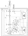
- FIG. 6 is a conceptual diagram showing an example of the configuration of the transmitter 11.
- the modulation unit 130 of the spatial light modulator 13 sets a region (first region) in which the phase image of the communication signal used for communication is set, and a phase image of a dummy signal for adding noise to the signal near the ghost image.
- the phase image is a pattern in which phase images corresponding to the images displayed on the projected surface are arranged in a tile shape.
- the modulation unit 130 When the light irradiated to the modulation unit 130 in the state where the phase image pattern of the communication signal is set in the first region and the phase image pattern of the dummy signal is set in the second region is reflected by the modulation unit 130. Is modulated into. The modulated light 140 reflected by the modulation unit 130 is transmitted as a spatial light signal 150 via the projection optical system 14.
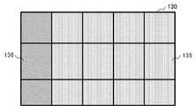
- FIG. 4 is a conceptual diagram for explaining an example of region allocation in the modulation unit 130 of the spatial light modulator of the transmitter 11.
- FIG. 3 shows an example in which the right side of the region in the modulation unit 130 is assigned to the first region 135 and the left end is assigned to the second region 136.
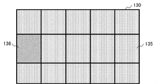
- FIG. 5 is a conceptual diagram for explaining another example of region allocation in the modulator 130 of the spatial light modulator of the transmitter 11.
- FIG. 4 shows an example in which the accuracy of the irradiation range of the light source that irradiates the modulation unit 130 of the spatial light modulator is high.
- the light transmission control unit 15 is connected to the light transmitter 11 and the communication control unit 19.
- the light transmission control unit 15 acquires a spatial optical signal pattern from the communication control unit 19.
- the light transmission control unit 15 transfers a phase image of an image to be transmitted as a spatial light signal (also referred to as a communication signal phase image) and a dummy signal phase image (also referred to as a dummy signal phase image) to the transmitter 11. It is displayed on the modulation unit 130 of the spatial light modulator of.
- the light transmission control unit 15 displays the phase image of the communication signal in the first region 135, displays the phase image of the dummy signal in the second region 136, and matches the pattern of the communication signal with the transmitter 11.
- the emission timing of the light source is controlled, and the modulation unit 130 is irradiated with light.
- the reflected light modulated by the modulation unit 130 is transmitted from the transmitter 11 as a spatial light signal.
- the receiver 17 is connected to the communication control unit 19.
- the receiver 17 receives a spatial optical signal transmitted from another communication system 10.
- the light receiver 17 transmits a signal corresponding to the pattern of the received spatial light signal (hereinafter, also referred to as a light receiving signal) to the communication control unit 19.
- the receiver 17 can be realized by an element such as a photodiode or a phototransistor. If the receiver 17 is realized by an avalanche photodiode, high-speed communication becomes possible.
- the receiver 17 may be realized by an element other than a photodiode, a phototransistor, or an avalanche photodiode, as long as the spatial optical signal can be converted into an electric signal. Further, the receiver 17 may be realized by a camera. When the light receiver 17 is realized by a camera, it is preferable to have a shutter speed sufficient to detect the pulse of the spatial light signal to be received.
- the communication control unit 19 is connected to the light transmission control unit 1 and the receiver 17.
- the communication control unit 19 outputs a spatial optical signal pattern to the light transmission control unit 15.
- the communication control unit 19 is connected to an external communication control system or communication control device, and outputs a light transmission pattern of a spatial optical signal based on an instruction received from those systems or devices to the light transmission control unit 15.
- the communication control unit 19 acquires a light receiving signal based on the spatial optical signal transmitted from the other communication system 10 from the light receiving device 17.
- the communication control unit 19 decodes the received signal.
- the communication control unit 19 transmits the decoded signal to an external communication control system or communication control device.
- FIG. 1 is an example, and does not limit the configuration of the communication system 10.
- the transmitter 11 includes a light source 12, a spatial light modulator 13, and a projection optical system 14.
- FIG. 6 is conceptual and does not accurately represent the positional relationship between each component, the light irradiation direction, and the like.
- the light source 12 is connected to the light transmission control unit 15.
- the light source 12 includes a first light source 121 that emits a laser beam 111 for a communication signal, a second light source 125 that emits a laser beam 113 for a dummy signal, and a mirror 129.
- the first light source 121 includes a first emitter 122 that emits a laser beam 111 in a specific wavelength region, and a collimator 123 that converts the laser beam 111 emitted from the first emitter 122 into parallel light 112.
- the first emitter 122 emits the laser beam 111 in a specific wavelength region according to the control of the light transmission control unit 15.
- the laser light 111 emitted from the first emitter 122 is converted into parallel light 112 by the collimator 123, and travels toward the first region 135 of the modulation unit 130 of the spatial light modulator 13.
- a part of the parallel light 112 emitted from the first emitter 122 is shielded by the mirror 129, and the second region 136 of the modulation unit 130 is not irradiated.
- the second light source 125 includes a second emitter 126 that emits a laser beam 113 in a specific wavelength region, and a collimator 127 that converts the laser beam 113 discarded from the second emitter 126 into parallel light 114.
- the second emitter 126 emits the laser beam 113 in a specific wavelength region according to the control of the light transmission control unit 15.
- the laser beam 113 emitted from the second emitter 126 is converted into parallel light 114 by the collimator 127 and irradiated to the reflecting surface of the mirror 129.
- the parallel light 114 reflected by the reflecting surface of the mirror 129 travels toward the second region 136 of the modulation unit 130 of the spatial light modulator 13.
- the composite light 115 which is a combination of the parallel light 112 emitted from the first light source 121 and the parallel light 114 emitted from the second light source 125, is applied to the modulation unit 130 of the spatial light modulator 13.
- the light source 12 emits the combined light 115, which is a combination of the parallel light 112 and the parallel light 114.
- the laser beam 111 emitted by the first emitter 122 and the laser beam 113 emitted by the second emitter 126 have the same wavelength region.
- the first emitter 122 and the second emitter 126 emit infrared light in the 1.55 micrometer band from the viewpoint of eye safety.
- the wavelength region of the light emitted by the first emitter 122 is not limited to the 1.55 micrometer band.
- the first emitter 122 may be configured to emit light having a wavelength in the visible region, or may be configured to emit light having a wavelength other than the visible region such as an infrared region or an ultraviolet region. May be good.
- the first emitter 122 may be replaced with one that emits light other than laser light, such as a light emitting diode, an incandescent light bulb, or a discharge tube, as long as it can emit directional light.
- the brightness of the laser beam 113 emitted by the second emitter 126 is controlled to be equal to the brightness of the ghost image formed by the laser beam 111 emitted by the first emitter 122.
- the output of the first emitter 122 is set to 50 milliwatts and the output of the second emitter 126 is set to 5 milliwatts.
- the wavelength region and brightness of the light emitted by the first emitter 122 and the second emitter 126 are not limited to the examples given here.
- the mirror 129 includes the first light source 121 and the spatial light modulator 13 so as to reflect the parallel light 114 emitted by the second emitter 126 toward the second region 136 of the modulation unit 130 of the spatial light modulator 13. Placed between.
- the parallel light 114 emitted by the second light source 125 is reflected by the reflecting surface of the mirror 129 and travels toward the second region 136 of the modulation unit 130 of the spatial light modulator 13.
- the incident angle of the combined light 115 is made non-vertical to the modulation unit 130 of the spatial light modulator 13. That is, in the present embodiment, the emission axis of the synthetic light 115 emitted from the light source 12 is oblique with respect to the modulation portion of the spatial light modulator 13. If the emission axis of the composite light 115 is set obliquely with respect to the modulation section 130 of the spatial light modulator 13, the composite light 115 can be incident on the modulation section 130 of the spatial light modulator 13 without using a beam splitter. The efficiency of light utilization can be improved. Further, if the emission axis of the combined light 115 is set obliquely with respect to the modulation unit 130 of the spatial light modulator 13, the size of the optical system of the transmitter 11 can be made compact.
- the spatial light modulator 13 is connected to the light transmission control unit 15.
- the spatial light modulator 13 has a modulation unit 130.
- the modulation unit 130 of the spatial light modulator 13 is assigned to the first region 135 and the second region 136.
- a phase image of a communication signal used for communication is displayed.
- a phase image of a dummy signal for adding noise to the signal near the ghost image is displayed.
- the phase image of the communication signal is displayed in the first region 135 and the phase image of the dummy signal is displayed in the second region 136 according to the control of the light transmission control unit 15.
- the position of the second region 136 is not particularly limited, but it is better to set it at a position around the modulation unit 130 because a shadow is formed on the portion shielded by the portion holding the mirror 129.
- the modulation unit 130 of the spatial light modulator 13 is irradiated with synthetic light from the light source 12 according to the control of the light transmission control unit 15.
- the phase image of the communication signal is displayed in the first region 135, and the phase image of the dummy signal is displayed in the second region 136, according to the pattern of the spatial light signal.
- the combined light 115 is irradiated.
- the modulated light 140 modulated by the modulation unit 130 of the spatial light modulator 13 is emitted.
- the modulated light 140 modulated by the modulation unit 130 of the spatial light modulator 13 travels toward the projection optical system 14.
- the spatial light modulator 13 modulates a phase image for displaying a desired image on the projected surface by setting the optical characteristics of each pixel of the modulation unit 130 according to the control of the light transmission control unit 15. It can be set in the unit 130.
- the modulation unit 130 of the spatial light modulator 13 is irradiated with light in a state where the phase image is set, the modulated light 140 whose spatial distribution is modulated according to the optical characteristics of the modulation unit 130 is emitted.
- a modulator that modulates the spatial distribution such as the phase, amplitude, intensity, polarization state, and propagation direction of light can be used.
- the spatial light modulator 13 can be realized by a phase modulation type spatial light modulator that modulates the phase of the incident composite light 115. Since the phase modulation type spatial light modulator 13 is focus-free, it is not necessary to change the focus for each distance even if the light is transmitted to the display areas set to a plurality of projection distances. If the phase modulation type spatial light modulator 13 is used, energy can be concentrated on the portion of the line constituting the image by sequentially switching the region where the spatial light signal is transmitted. Therefore, if the phase modulation type spatial light modulator 13 is used, if the output of the light source is the same, the image can be displayed brighter than the method of transmitting light over the entire display area.
- a phase image corresponding to an image to be displayed on the projected surface is set in the modulation unit 130 of the phase modulation type spatial light modulator 13.
- the phase image is a pattern in which phase images corresponding to the images to be displayed on the projected surface are arranged in a tile shape.
- the modulated light 140 reflected by the modulation unit 130 of the spatial light modulator 13 becomes an image as if a kind of diffraction grating formed an aggregate, and the image is formed so that the light diffracted by the diffraction grating is collected. It is formed.
- the spatial light modulator 13 is realized by a spatial light modulator using a ferroelectric liquid crystal, a homogeneous liquid crystal, a vertically oriented liquid crystal, or the like.
- the spatial light modulator 13 can be realized by LCOS (Liquid Crystal on Silicon).
- the spatial light modulator 13 may be realized by a MEMS (Micro Electro Mechanical System). Examples of the MEMS that realizes the spatial light modulator 13 include a two-dimensional MEMS and a one-dimensional MEMS. When emitting laser light in the ultraviolet region or infrared region, MEMS may be more suitable than LCOS.
- the projection optical system 14 is an optical system that transmits the modulated light 140 modulated by the spatial light modulator 13 as a spatial light signal 150. As shown in FIG. 6, the projection optical system 14 includes a Fourier transform lens 141, an aperture 143, and a projection lens 145.
- the Fourier transform lens 141 is an optical lens that forms an image formed when the modulated light 140 modulated by the modulation unit 130 of the spatial light modulator 13 is projected at infinity at a nearby focal position. In the example of FIG. 6, the focus is formed at the position of the aperture 143.
- the aperture 143 shields the higher-order light contained in the light focused by the Fourier transform lens 141, and specifies the extension of the display area.
- the opening of the aperture 143 is opened smaller than the outer circumference of the display area at the position of the aperture 143, and is installed so as to block the peripheral area of the image at the position of the aperture 143.
- the opening of the aperture 143 is formed in a rectangular or circular shape.
- the aperture 143 is preferably installed at the focal position of the Fourier transform lens 141.
- the aperture 143 may be deviated from the focal position as long as the higher-order light can be shielded and the display area can be specified.
- the projection lens 145 is an optical lens that magnifies and projects the light focused by the Fourier transform lens 141.
- the projection lens 145 transmits the spatial light signal 150 so that an image corresponding to the phase image set in the modulation unit 130 of the spatial light modulator 13 is formed on the projected surface.
- FIG. 6 is an example and does not limit the configuration of the transmitter 11.
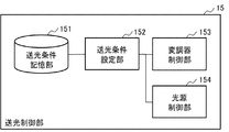
- FIG. 7 is a block diagram showing an example of the configuration of the light transmission control unit 15.
- the light transmission control unit 15 includes a light transmission condition storage unit 151, a light transmission condition setting unit 152, a modulator control unit 153, and a light source control unit 154.
- the light transmission condition storage unit 151 stores a phase image corresponding to the shape of the spatial light signal 150.
- the shape of the spatial optical signal 150 is a circle, a quadrangle, or the like.
- the light transmission condition storage unit 151 includes light source control conditions for controlling the first emitter 122 and the second emitter 126 included in the light source 12, and modulation element control for controlling the spatial light modulator 13. The light transmission conditions including the conditions are stored.
- the light transmission condition setting unit 152 sets the light transmission conditions for transmitting the spatial light signal 150. Specifically, the light transmission condition setting unit 152 sets the modulation element control conditions for setting the phase image corresponding to the spatial light signal 150 in the modulation unit 130 of the spatial light modulator 13 in the modulator control unit 153. .. Further, the light transmission condition setting unit 152 sets the light source control conditions for emitting the laser light from the first emitter 122 and the second emitter 126 in the light source control unit 154. The light transmission condition setting unit 152 synchronizes the timing of setting the modulation element control condition in the modulator control unit 153 with the timing of setting the light source control condition in the light source control unit 154 to obtain a desired spatial light signal 150. Light is transmitted from the transmitter 11.
- the modulator control unit 153 receives the phase image corresponding to the spatial optical signal 150 and the modulation element control condition from the light transmission condition setting unit 152.
- the modulator control unit 153 drives a driver (not shown) that sets the modulation unit 130 of the spatial light modulator 13 according to the modulation element control condition received from the light transmission condition setting unit 152, and drives the spatial light modulator 13.
- a phase image is set in the modulation unit 130 of the above.
- the light source control unit 154 receives the light source control condition from the light transmission condition setting unit 152.
- the light source control unit 154 drives a drive unit (not shown) of the first emitter 122 and the second emitter 126 according to the received light source control condition, and lasers from the first emitter 122 and the second emitter 126. Light is emitted.
- the timing at which the phase image is set in the modulation unit 130 of the spatial light modulator 13 and the timing at which the composite light 115 is irradiated to the modulation unit 130 in which the phase image is set are synchronized by the light transmission condition setting unit 152. .. Therefore, the modulation unit 130 in the state where the phase image is set is irradiated with the composite light 115, and the modulation light 140 converted from the composite light 115 is transmitted as a spatial light signal 150 by the projection optical system 14.
- FIG. 7 is an example and does not limit the configuration of the light transmission control unit 15.
- FIG. 8 is a block diagram showing an example of the configuration of the communication control unit 19.
- the communication control unit 19 includes a spatial optical signal setting unit 191 and a decoder 193.
- the spatial light signal setting unit 191 sets the light transmission pattern of the spatial light signal to be transmitted to the light transmission control unit 15.
- the spatial optical signal setting unit 191 converts a signal input via a system or device (not shown) using the communication system 10 into a light transmission pattern of the spatial optical signal.
- the spatial light signal setting unit 191 outputs the converted light transmission pattern to the light transmission condition setting unit 152 of the light transmission control unit 15.
- the decoder 193 receives from the receiver 17 a light receiving signal corresponding to the spatial optical signal received from the other communication system 10. The decoder 193 decodes the received signal. The decoder 193 transmits the decoded signal to a system or device (not shown) that uses the communication system 10.
- FIG. 7 is an example and does not limit the configuration of the light transmission control unit 15.
- the communication system of the present embodiment outputs the light transmission device, the receiver that receives the spatial light signal transmitted from other devices, and the light transmission pattern of the spatial light signal to the light transmission control unit. It also includes a communication control unit that decodes the spatial optical signal received by the light receiver.
- the light transmitter of the present embodiment adds a transmitter that transmits a spatial optical signal including a communication signal and a dummy signal having the same brightness as the ghost image of the communication signal to the spatial optical signal at the position of the ghost image. It includes a light transmission control unit that controls the transmitter so that a dummy signal is displayed.
- the transmitter has a spatial light modulator, a light source, and a projection optical system.
- the spatial light modulator is a modulation unit assigned to a first region in which a pattern of a phase image of a communication signal is set and a second region in which a pattern of a phase image of a dummy signal superimposed on a ghost image of a communication signal is set.
- the light source includes a first light source that emits light for transmitting a communication signal toward the first region and a second light source that emits light for transmitting a dummy signal toward the second region.
- the projection optical system emits light emitted from the first light source and the second light source and modulated by the modulation unit, and transmits the light as a spatial light signal.
- the light transmission control unit sets the phase image pattern of the communication signal in the first region and the phase image pattern of the dummy signal in the second region. Then, the light transmission control unit controls the timing at which the light is emitted from the first light source so as to match the light transmission timing of the spatial light signal, and the light from the second light source so as to deviate from the light transmission timing of the spatial light signal. Controls the timing at which is emitted.
- the light transmission control unit controls the output of the second light source so that the brightness of the ghost image of the communication signal emitted from the first light source and the brightness of the dummy signal are equal to each other.
- the light transmission control unit controls the emission timing of the first light source according to the light transmission timing of the spatial light signal, and determines the brightness of the ghost image of the communication signal emitted from the first light source.
- the output of the second light source is controlled so that the brightness of the dummy signals is equal.
- the light transmitter is arranged between the first light source and the spatial light modulator, and includes a mirror that reflects the light emitted from the second light source toward the second region.
- the signal that can be received at the position of the ghost image becomes undecipherable. Therefore, according to the present embodiment, security in spatial optical communication can be improved.
- the communication system of the present embodiment is different from the first embodiment in that a ghost image is diffused by displaying a composite image obtained by synthesizing a virtual lens image and a phase image on a modulation unit of a spatial light modulator.
- the configurations of the transmitter and the light transmission control unit are different from those of the first embodiment. In the following, the description of the configuration similar to that of the first embodiment may be omitted.
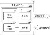
- FIG. 9 is a block diagram showing an example of the configuration of the communication system 20 of the present embodiment.
- the communication system 20 includes a transmitter 21, a light transmission control unit 25, a light receiver 27, and a communication control unit 29.
- the light transmitter 21 and the light transmission control unit 25 constitute a light transmission device 200.
- the light transmission control unit 25 and the communication control unit 29 constitute a control device 210. Since each of the receiver 27 and the communication control unit 29 is the same as the receiver 17 and the communication control unit 19 of the first embodiment, the description thereof will be omitted.
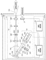
- FIG. 10 is a conceptual diagram showing an example of the configuration of the transmitter 21.
- the transmitter 21 includes a light source 22, a spatial light modulator 23 having a modulator 230, and a projection optical system 24.
- the light source 22 includes a first light source 221 that emits parallel light 212 for communication signals, a second light source 225 that emits parallel light 214 for dummy signals, and a mirror 229.
- the first light source 221 includes a first emitter 222 and a collimator 223.
- the laser light 211 emitted from the first light source 221 is converted into parallel light 212 by the collimator 223.
- the second light source 225 includes a second emitter 226 and a collimator 227.
- the laser light 213 emitted from the second light source 225 is converted into parallel light 214 by the collimator 227. Since each of the configurations included in the light source 22 and the spatial light modulator 23 is the same as each of the configurations included in the light source 12 and the spatial light modulator 13 of the first embodiment, the description thereof will be omitted. Note that FIG. 10 is conceptual and does not accurately represent the positional relationship between each component, the light irradiation direction, and the like.
- FIG. 11 is an example of a composite image 570 obtained by adding and synthesizing a virtual lens image 560 having a focal length + f and a phase image 550.
- the virtual lens image 560 is a lens pattern for condensing an image to be displayed on the projected surface at a position of focal length + f.
- the composite image is a pattern in which the phase image 550 and the virtual lens image 560 are combined.
- the wave surface of light can be controlled by phase control in the same way as diffraction.
- phase control in the same way as diffraction.
- the virtual lens image 560 is a pattern that causes a lens effect of changing the phase of the incident light (synthetic light 215) on the modulation unit 230 of the spatial light modulator 23 spherically and condensing the light at a predetermined focal length. ..
- the virtual lens image 560 can be controlled independently of the phase image. For example, in order to condense the modulated light 240 at the position of the 0th-order light shield 242, one lens shape pattern is displayed as a virtual lens image on the modulation unit 230 of the spatial light modulator 23.
- the projection optical system 24 includes a Fourier transform lens 241, a 0th-order light shield 242, an aperture 243, and a projection lens 245.
- the projection optical system 24 differs from the projection optical system 14 of the first embodiment in that it includes a 0th-order light shield 242. Since each of the Fourier transform lens 241 and the aperture 243 and the projection lens 245 is the same as each of the Fourier transform lens 141, the aperture 143, and the projection lens 145 of the first embodiment, detailed description thereof will be omitted. If it is sufficient to diffuse the ghost image by the virtual lens, the 0th-order light shield 242 may be omitted.
- the 0th-order light shield 242 includes a holding member 2421 and a light absorbing member 2423.
- the holding member 2421 is a member that holds the light absorbing member 2423.
- the holding member 2421 is made of a material that easily transmits light, such as glass or plastic.
- the holding member 2421 is made of plastic, it is preferable to use a material having a uniform entire surface and a small phase unevenness so that retardation is unlikely to occur.
- a plastic material in which birefringence is suppressed is suitable.
- the holding member 2421 may be configured to include a wire rod for fixing the light absorbing member 2423.
- the peripheral edge of the holding member 2421 can be formed in a frame shape, a wire rod can be stretched around the inside of the opening of the frame, and the light absorbing member 2423 can be fixed by the stretched wire rod.
- the holding member 2421 is made of a wire rod, it may be made of a material that is less likely to be deteriorated by light so that deterioration is less likely to occur by irradiation with light, or a wire rod thin enough not to be exposed to light may be used.
- the light absorbing member 2423 is held by the holding member 2421 and is arranged at the focal position of the virtual lens.
- the light absorbing member 2423 is made of a black body such as carbon.
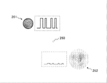
- FIG. 12 is a conceptual diagram for explaining a ghost image that can be generated on the optical path of the communication signal 261 transmitted from the transmitter 21.
- the spatial light signal transmitted from the transmitter 21 does not include 0th-order light, but in order to make it easier to explain the position of the ghost image, FIG. 12 shows virtual 0th-order light (virtual 0th-order light).
- Light 260 is illustrated. Since there is a 0th order light shield 242, the communication signal 261 transmitted from the transmitter 21 does not include the virtual 0th order light 260.
- the spatial optical signal transmitted from the transmitter 21 includes a ghost image 262 at a position point-symmetrical to the communication signal 261 with the virtual 0th-order light 260 as the center.
- FIG. 12 is a conceptual diagram for explaining a ghost image that can be generated on the optical path of the communication signal 261 transmitted from the transmitter 21.
- the spatial light signal transmitted from the transmitter 21 does not include 0th-order light, but in order to make it easier to explain the position of the
- FIG. 12 shows an example of the pattern of the communication signal 261 (inside the broken line) on the right side of the communication signal 261 and an example of the pattern of the ghost image 262 (inside the alternate long and short dash line) on the left side of the communication signal 261.
- FIG. 12 shows that the brightness of the ghost image 262 is considerably smaller than the brightness of the communication signal 261.
- the ghost image 262 of the present embodiment is darker than the ghost image 162 of the first embodiment because it is diffused by using a virtual lens. Similar to the first embodiment, the ghost image 262 of the present embodiment is a primary ghost image.
- the communication signal 261 transmitted from the transmitter 21 includes a high-order ghost image. Since the higher-order ghost image included in the communication signal 261 is the same as the higher-order ghost image included in the communication signal 161 of the first embodiment, the description thereof will be omitted.
- FIG. 13 is a timing chart for explaining an example of adding noise to the ghost image included in the spatial light signal transmitted from the transmitter 21.
- the brightness of the ghost image included in the spatial light signal transmitted from the transmitter 21 is darker than the brightness of the communication signal. Therefore, from the transmitter 21, a dummy signal having the same brightness as the brightness of the ghost image is mixed with the spatial light signal. Therefore, a composite signal in which the ghost image and the dummy signal are combined is displayed in the region including the ghost image. As a result, even if the area including the ghost image is analyzed, the communication signal is not leaked. By transmitting the dummy signal to the region including the ghost image, the ghost image of the dummy signal appears in the region of the communication signal. However, since the brightness of the ghost image of the dummy signal is very dark compared to the brightness of the communication signal, there is almost no effect on the communication signal.
- the spatial light modulator 23 has a modulator 230 that displays a phase image according to the spatial light signal to be transmitted.
- the modulator of the spatial light modulator displays a region (first region) in which the phase image of the communication signal used for communication is displayed and a phase image of a dummy signal for adding noise to the signal near the ghost image. Includes a region (second region).
- the transmitter 21 irradiates the modulation unit 230 with light in a state where the phase image of the communication signal is displayed in the first region and the phase image of the dummy signal is displayed in the second region, and is modulated by the modulation unit 230.
- the reflected light is transmitted as a spatial light signal.
- FIG. 14 is a conceptual diagram for explaining an example of allocation of the modulation unit 230 of the spatial light modulator 23 of the transmitter 21.
- FIG. 14 shows an example in which the right side of the modulation unit 230 is assigned to the first region 235 and the left end is assigned to the second region 236.
- a composite image also referred to as a first composite image
- a composite image obtained by adding a first virtual lens focusing on the first focal point (+ f) and a phase image of a communication signal is assigned to the first region 235.
- the second region 236 is assigned a composite image (also referred to as a second composite image) in which the second virtual lens focusing on the second focal point ( ⁇ f) and the phase image of the dummy signal are added together.
- a diffused ghost image 262 is projected as shown in FIG. That is, when the first virtual lens is applied to the phase image of the communication signal 261, the ghost image 262 becomes an image with a blurred focus.
- a dummy signal similar to the blurred ghost image 262 may be displayed at the position of the ghost image 262.
- the first virtual lens focusing on the first focus (+ f) is applied to a dummy signal whose brightness is originally low, the dummy signal itself is not blurred, so the dummy signal before the first virtual lens is applied is a ghost image. It is displayed at the position of 262. Therefore, by applying a second virtual lens that focuses on the second focal point (-f) to the dummy signal, the blurred dummy signal is displayed at the position of the ghost image 262 so that the ghost image 262 is less likely to be detected. To do.
- Applying a second virtual lens that focuses on the second focus (-f) is equivalent to blurring the original image by emphasizing the ghost image.
- the dummy signal blurred by applying the first virtual lens that focuses on the first focal point (+ f) is displayed at the position of the ghost image 262
- the ghost image 262 becomes clear.
- an image in which the communication signal 261 is blurred is displayed at the position of the communication signal 261 although it is considerably dark.
- a blurred image is mixed with the communication signal 261, it becomes difficult to detect the communication signal 261.
- the second virtual lens that focuses on the second focus (-f) is applied to the dummy signal to display the blurred dummy signal at the position of the ghost image 262 and the clear dummy signal to be displayed at the position of the communication signal 261. Makes the ghost image 262 less likely to be detected.
- the light transmission control unit 25 acquires a spatial optical signal pattern from the communication control unit 29.
- the light transmission control unit 25 causes the modulation unit 230 of the spatial light modulator 23 of the transmitter 21 to display the first composite image of the communication signal to be transmitted as the spatial light signal and the second composite image of the dummy signal. ..
- the light transmission control unit 25 matches the light transmission pattern of the communication signal with the first composite image of the communication signal displayed in the first region 235 and the second composite image of the dummy signal displayed in the second region 236.
- the emission timing of the light source of the transmitter 21 is controlled, and the modulation unit 230 is irradiated with light.
- the reflected light modulated by the modulation unit 230 is transmitted from the transmitter 21 as a spatial light signal.
- FIGS. 9 to 10 are examples, and the configuration of the communication system 20 is not limited.
- FIG. 15 is a block diagram showing an example of the configuration of the light transmission control unit 25.
- the light transmission control unit 25 includes a light transmission condition storage unit 251, a light transmission condition setting unit 252, a modulator control unit 253, a light source control unit 254, a virtual lens image storage unit 256, and an image composition unit 257.
- the light transmission condition storage unit 251 stores a phase image corresponding to the shape of the spatial light signal 250.
- the shape of the spatial optical signal 250 is a circle, a quadrangle, or the like.
- the light transmission condition storage unit 251 includes light source control conditions for controlling the first emitter 222 and the second emitter 226 included in the light source 22, and modulation element control for controlling the spatial light modulator 23.
- the light transmission conditions including the conditions are stored.
- the virtual lens image is stored in the virtual lens image storage unit 256.
- the virtual lens image stored in the virtual lens image storage unit 256 has a lens effect for condensing the modulated light 240 at the position of the 0th-order light shield 242.
- the virtual lens image storage unit 256 may store a plurality of virtual lens images according to the focal length.
- the image synthesizing unit 257 acquires a phase image from the light transmission condition storage unit 251 and acquires a virtual lens image from the virtual lens image storage unit 256.
- the image synthesizing unit 257 synthesizes the phase image and the virtual lens image.
- the image synthesizing unit 257 outputs the combined image after synthesizing to the light transmission condition setting unit 252.
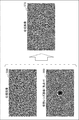
- FIG. 16 is an example of a composite image 571 of a communication signal generated by adding the phase image of the virtual lens image 561 (focus + f) and the phase image of the phase image 551 of the communication signal.
- FIG. 17 is an example of a composite image 572 of the dummy signal generated by adding the phase image of the virtual lens image 562 (focus ⁇ f) and the phase image of the dummy signal phase image 552.
- the first partial image 581 of the first region (the region inside the solid line) of the composite image 571 and the second partial image 582 of the second region (the region inside the broken line) of the composite image 572 of the dummy signal are shown. This is an example of the composite image 580.
- the dummy signal is superimposed and displayed at the position of the ghost image of the communication signal. Signal leakage can be suppressed.
- the light transmission condition setting unit 252 sets the light transmission conditions for transmitting the spatial light signal 250. Specifically, the light transmission condition setting unit 252 sets the modulation element control conditions for setting the composite image corresponding to the spatial light signal 250 in the modulation unit 230 of the spatial light modulator 23 in the modulator control unit 253. .. Further, the light transmission condition setting unit 252 sets the light source control condition for emitting the laser light from the first emitter 222 and the second emitter 226 in the light source control unit 254. The light transmission condition setting unit 252 synchronizes the timing of setting the modulation element control condition with the modulator control unit 253 with the timing of setting the light source control condition with the light source control unit 254 to obtain a desired spatial light signal 250. Light is transmitted from the transmitter 21.
- the modulator control unit 253 receives the composite image corresponding to the spatial optical signal 250 and the modulation element control condition from the light transmission condition setting unit 252.
- the modulator control unit 253 drives a driver (not shown) that sets the modulation unit 230 of the spatial light modulator 23 according to the modulation element control condition received from the light transmission condition setting unit 252, and drives the spatial light modulator 23.
- a composite image is set in the modulation unit 230 of the above.
- the light source control unit 254 receives the light source control condition from the light transmission condition setting unit 252.
- the light source control unit 254 drives a drive unit (not shown) of the first emitter 222 and the second emitter 226 according to the received light source control condition, and lasers from the first emitter 222 and the second emitter 226. Light is emitted.
- the timing at which the composite image is set in the modulation unit 230 of the spatial light modulator 23 and the timing at which the composite light 215 is irradiated to the modulation unit 230 in which the composite image is set are synchronized by the light transmission condition setting unit 252. .. Therefore, the modulation unit 230 in the state where the composite image is set is irradiated with the composite light 215, and the modulated light 240 converted from the composite light 215 is transmitted as a spatial light signal 250 by the projection optical system 24.
- FIG. 15 is an example and does not limit the configuration of the light transmission control unit 25.
- the light transmission control unit of the present embodiment has a first composite image in which the first virtual lens focusing on the first focus is applied to the phase image of the communication signal, and a second virtual image focusing on the second focus.
- a second composite image in which the lens is applied to the phase image of the dummy signal is generated.
- the light transmission control unit allocates the pattern of the first partial image included in the first composite image to the first region, and assigns the pattern of the second partial image included in the second composite image to the second region.
- the projection optical system includes a 0th-order light shield that shields the 0th-order light contained in the light modulated by the spatial light modulator.
- the focus position of the ghost image which is the conjugate image of the communication signal, can be shifted and blurred, so that the ghost image is less likely to be detected.
- Combining a virtual lens and a dummy signal can further enhance security in spatial optical communication.
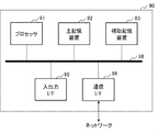
- the information processing apparatus 90 of FIG. 19 is a configuration example for executing the processing of the control unit of each embodiment, and does not limit the scope of the present invention.
- the information processing device 90 includes a processor 91, a main storage device 92, an auxiliary storage device 93, an input / output interface 95, and a communication interface 96.
- the interface is abbreviated as I / F (Interface).
- the processor 91, the main storage device 92, the auxiliary storage device 93, the input / output interface 95, and the communication interface 96 are connected to each other via a bus 98 so as to be capable of data communication. Further, the processor 91, the main storage device 92, the auxiliary storage device 93, and the input / output interface 95 are connected to a network such as the Internet or an intranet via the communication interface 96.
- the processor 91 expands the program stored in the auxiliary storage device 93 or the like into the main storage device 92, and executes the expanded program.
- the software program installed in the information processing apparatus 90 may be used.
- the processor 91 executes the process by the control unit according to the present embodiment.
- the main storage device 92 has an area in which the program is expanded.
- the main storage device 92 may be, for example, a volatile memory such as a DRAM (Dynamic Random Access Memory). Further, a non-volatile memory such as MRAM (Magnetoresistive Random Access Memory) may be configured / added as the main storage device 92.
- a volatile memory such as a DRAM (Dynamic Random Access Memory).
- a non-volatile memory such as MRAM (Magnetoresistive Random Access Memory) may be configured / added as the main storage device 92.
- the auxiliary storage device 93 stores various data.
- the auxiliary storage device 93 is composed of a local disk such as a hard disk or a flash memory. It is also possible to store various data in the main storage device 92 and omit the auxiliary storage device 93.
- the input / output interface 95 is an interface for connecting the information processing device 90 and peripheral devices.
- the communication interface 96 is an interface for connecting to an external system or device through a network such as the Internet or an intranet based on a standard or a specification.
- the input / output interface 95 and the communication interface 96 may be shared as an interface for connecting to an external device.
- the information processing device 90 may be configured to connect an input device such as a keyboard, a mouse, or a touch panel, if necessary. These input devices are used to input information and settings. When the touch panel is used as an input device, the display screen of the display device may also serve as the interface of the input device. Data communication between the processor 91 and the input device may be mediated by the input / output interface 95.
- the information processing device 90 may be equipped with a display device for displaying information.
- a display device it is preferable that the information processing device 90 is provided with a display control device (not shown) for controlling the display of the display device.
- the display device may be connected to the information processing device 90 via the input / output interface 95.
- the above is an example of the hardware configuration for enabling the control unit according to each embodiment of the present invention.
- the hardware configuration of FIG. 19 is an example of a hardware configuration for executing arithmetic processing of the control unit according to each embodiment, and does not limit the scope of the present invention.
- the scope of the present invention also includes a program for causing a computer to execute a process related to a control unit according to each embodiment.
- a program recording medium on which the program according to each embodiment is recorded is also included in the scope of the present invention.
- the recording medium can be realized by, for example, an optical recording medium such as a CD (Compact Disc) or a DVD (Digital Versatile Disc). Further, the recording medium may be realized by a semiconductor recording medium such as a USB (Universal Serial Bus) memory or an SD (Secure Digital) card, a magnetic recording medium such as a flexible disk, or another recording medium.
- an optical recording medium such as a CD (Compact Disc) or a DVD (Digital Versatile Disc).
- the recording medium may be realized by a semiconductor recording medium such as a USB (Universal Serial Bus) memory or an SD (Secure Digital) card, a magnetic recording medium such as a flexible disk, or another recording medium.
- USB Universal Serial Bus
- SD Secure Digital
- the components of the control unit of each embodiment can be arbitrarily combined. Further, the components of the control unit of each embodiment may be realized by software or by a circuit.
Landscapes
- Physics & Mathematics (AREA)
- Engineering & Computer Science (AREA)
- Signal Processing (AREA)
- Electromagnetism (AREA)
- Computer Networks & Wireless Communication (AREA)
- Nonlinear Science (AREA)
- Multimedia (AREA)
- General Physics & Mathematics (AREA)
- Optics & Photonics (AREA)
- Optical Communication System (AREA)
- Optical Modulation, Optical Deflection, Nonlinear Optics, Optical Demodulation, Optical Logic Elements (AREA)
- Mechanical Light Control Or Optical Switches (AREA)
Abstract
Afin d'améliorer la sécurité de la communication de lumière spatiale, la présente invention concerne un dispositif de transmission de lumière et similaire, le dispositif de transmission de lumière étant pourvu d'un transmetteur de lumière qui transmet un signal de lumière spatiale comprenant un signal de communication, et une unité de commande de transmission de lumière qui ajoute un signal factice ayant la même luminosité qu'une image fantôme du signal de communication au signal de lumière spatiale, et commande le transmetteur de lumière de telle sorte que le signal fictif se trouve affiché à l'emplacement de l'image fantôme.
Priority Applications (1)
| Application Number | Priority Date | Filing Date | Title |
|---|---|---|---|
| US17/781,442 US12063459B2 (en) | 2019-12-12 | 2020-11-10 | Light transmitting device, communication system, and light transmitting method |
Applications Claiming Priority (2)
| Application Number | Priority Date | Filing Date | Title |
|---|---|---|---|
| JP2019-224203 | 2019-12-12 | ||
| JP2019224203A JP6949927B2 (ja) | 2019-12-12 | 2019-12-12 | 送光装置、通信システム、および送光方法 |
Publications (1)
| Publication Number | Publication Date |
|---|---|
| WO2021117403A1 true WO2021117403A1 (fr) | 2021-06-17 |
Family
ID=76310839
Family Applications (1)
| Application Number | Title | Priority Date | Filing Date |
|---|---|---|---|
| PCT/JP2020/041899 Ceased WO2021117403A1 (fr) | 2019-12-12 | 2020-11-10 | Dispositif de transmission de lumière, système de communication et procédé de transmission de lumière |
Country Status (3)
| Country | Link |
|---|---|
| US (1) | US12063459B2 (fr) |
| JP (1) | JP6949927B2 (fr) |
| WO (1) | WO2021117403A1 (fr) |
Families Citing this family (1)
| Publication number | Priority date | Publication date | Assignee | Title |
|---|---|---|---|---|
| WO2023026461A1 (fr) * | 2021-08-27 | 2023-03-02 | 日本電気株式会社 | Dispositif de projection et dispositif de communication |
Citations (6)
| Publication number | Priority date | Publication date | Assignee | Title |
|---|---|---|---|---|
| JPH08251520A (ja) * | 1995-03-08 | 1996-09-27 | Nikon Corp | ビデオプロジェクター |
| WO2012120853A1 (fr) * | 2011-03-04 | 2012-09-13 | 国立大学法人徳島大学 | Procédé et dispositif de fourniture d'informations |
| JP2016176996A (ja) * | 2015-03-18 | 2016-10-06 | アルプス電気株式会社 | 画像投影装置 |
| WO2016199415A1 (fr) * | 2015-06-12 | 2016-12-15 | 日本電気株式会社 | Dispositif d'entrée d'informations et système d'appariement |
| WO2016208171A1 (fr) * | 2015-06-23 | 2016-12-29 | 日本電気株式会社 | Dispositif de projection, système de projection et appareil d'interface |
| WO2018101097A1 (fr) * | 2016-11-30 | 2018-06-07 | 日本電気株式会社 | Système de projection, procédé de projection et support d'enregistrement de programme |
Family Cites Families (5)
| Publication number | Priority date | Publication date | Assignee | Title |
|---|---|---|---|---|
| JP2614633B2 (ja) * | 1988-03-11 | 1997-05-28 | 日本電気ホームエレクトロニクス株式会社 | ゴースト除去装置 |
| JP4100299B2 (ja) * | 2003-08-29 | 2008-06-11 | ソニー株式会社 | 駆動装置、駆動方法及び表示パネル駆動システム |
| US8446148B2 (en) * | 2008-08-29 | 2013-05-21 | Siemens Medical Solutions Usa, Inc. | Long T1 artifact suppression techniques for magnetic resonance imaging |
| US8942571B2 (en) * | 2012-12-24 | 2015-01-27 | Industrial Technology Research Institute | Apparatus and method for data embedding in light communication and the light communication system and method thereof |
| WO2015049866A1 (fr) | 2013-10-02 | 2015-04-09 | 日本電気株式会社 | Appareil d'interface, module, composant de commande, procédé de commande, et support stockage de programme |
-
2019
- 2019-12-12 JP JP2019224203A patent/JP6949927B2/ja active Active
-
2020
- 2020-11-10 WO PCT/JP2020/041899 patent/WO2021117403A1/fr not_active Ceased
- 2020-11-10 US US17/781,442 patent/US12063459B2/en active Active
Patent Citations (6)
| Publication number | Priority date | Publication date | Assignee | Title |
|---|---|---|---|---|
| JPH08251520A (ja) * | 1995-03-08 | 1996-09-27 | Nikon Corp | ビデオプロジェクター |
| WO2012120853A1 (fr) * | 2011-03-04 | 2012-09-13 | 国立大学法人徳島大学 | Procédé et dispositif de fourniture d'informations |
| JP2016176996A (ja) * | 2015-03-18 | 2016-10-06 | アルプス電気株式会社 | 画像投影装置 |
| WO2016199415A1 (fr) * | 2015-06-12 | 2016-12-15 | 日本電気株式会社 | Dispositif d'entrée d'informations et système d'appariement |
| WO2016208171A1 (fr) * | 2015-06-23 | 2016-12-29 | 日本電気株式会社 | Dispositif de projection, système de projection et appareil d'interface |
| WO2018101097A1 (fr) * | 2016-11-30 | 2018-06-07 | 日本電気株式会社 | Système de projection, procédé de projection et support d'enregistrement de programme |
Also Published As
| Publication number | Publication date |
|---|---|
| US20220417478A1 (en) | 2022-12-29 |
| JP2021093663A (ja) | 2021-06-17 |
| US12063459B2 (en) | 2024-08-13 |
| JP6949927B2 (ja) | 2021-10-13 |
Similar Documents
| Publication | Publication Date | Title |
|---|---|---|
| US11392014B2 (en) | Projection device, interface device, and projection method | |
| US9013641B2 (en) | Projection type image display device | |
| WO2018056194A1 (fr) | Système de projection | |
| WO2018101097A1 (fr) | Système de projection, procédé de projection et support d'enregistrement de programme | |
| JP2005055855A (ja) | デジタル光処理投影システム及びその投影方法 | |
| WO2021199574A1 (fr) | Dispositif d'affichage | |
| CN107505824A (zh) | 一种光学调制方法及装置、一种全息显示设备 | |
| JP6949927B2 (ja) | 送光装置、通信システム、および送光方法 | |
| JP6427085B2 (ja) | 画像表示装置 | |
| CN116685895A (zh) | 利用相位光调制器的滚动激光照射 | |
| KR20090114645A (ko) | 레이저 프로젝션 장치 | |
| JP6187141B2 (ja) | 画像表示装置及び非平面型スクリーン | |
| JP7613556B2 (ja) | 投射装置および投射方法 | |
| US20240348754A1 (en) | Projection device, projection control method, and recording medium | |
| WO2022137777A1 (fr) | Dispositif et procédé de projection | |
| US12284466B2 (en) | Projection device, control method, and recording medium | |
| JP7574943B2 (ja) | 通信制御装置、通信装置、通信制御方法、およびプログラム | |
| KR20070029231A (ko) | 레이저디스플레이장치를 위한 스페클저감장치 | |
| JP7589824B2 (ja) | 投射装置および通信装置 | |
| WO2023026520A1 (fr) | Dispositif de projection, procédé de commande de projection et support d'enregistrement | |
| US20240283537A1 (en) | Transmitter, transmission device, communication device, and communication system | |
| JPWO2019180813A1 (ja) | 受光装置および送受光装置 | |
| KR100234303B1 (ko) | 반사형 프로젝트장치 | |
| JP7622858B2 (ja) | 送光装置、通信装置、制御方法、およびプログラム | |
| JP7559961B2 (ja) | 送光装置および通信装置 |
Legal Events
| Date | Code | Title | Description |
|---|---|---|---|
| 121 | Ep: the epo has been informed by wipo that ep was designated in this application |
Ref document number: 20898613 Country of ref document: EP Kind code of ref document: A1 |
|
| NENP | Non-entry into the national phase |
Ref country code: DE |
|
| 122 | Ep: pct application non-entry in european phase |
Ref document number: 20898613 Country of ref document: EP Kind code of ref document: A1 |