WO2016208498A1 - Structure d'isolation acoustique pour véhicules automobiles, élément de fixation pour matériau insonorisant pour véhicules automobiles et matériau insonorisant - Google Patents
Structure d'isolation acoustique pour véhicules automobiles, élément de fixation pour matériau insonorisant pour véhicules automobiles et matériau insonorisant Download PDFInfo
- Publication number
- WO2016208498A1 WO2016208498A1 PCT/JP2016/068033 JP2016068033W WO2016208498A1 WO 2016208498 A1 WO2016208498 A1 WO 2016208498A1 JP 2016068033 W JP2016068033 W JP 2016068033W WO 2016208498 A1 WO2016208498 A1 WO 2016208498A1
- Authority
- WO
- WIPO (PCT)
- Prior art keywords
- absorbing material
- sound absorbing
- sound
- panel
- component
- Prior art date
- Legal status (The legal status is an assumption and is not a legal conclusion. Google has not performed a legal analysis and makes no representation as to the accuracy of the status listed.)
- Ceased
Links
Images











Classifications
-
- B—PERFORMING OPERATIONS; TRANSPORTING
- B60—VEHICLES IN GENERAL
- B60R—VEHICLES, VEHICLE FITTINGS, OR VEHICLE PARTS, NOT OTHERWISE PROVIDED FOR
- B60R13/00—Elements for body-finishing, identifying, or decorating; Arrangements or adaptations for advertising purposes
- B60R13/08—Insulating elements, e.g. for sound insulation
-
- G—PHYSICS
- G10—MUSICAL INSTRUMENTS; ACOUSTICS
- G10K—SOUND-PRODUCING DEVICES; METHODS OR DEVICES FOR PROTECTING AGAINST, OR FOR DAMPING, NOISE OR OTHER ACOUSTIC WAVES IN GENERAL; ACOUSTICS NOT OTHERWISE PROVIDED FOR
- G10K11/00—Methods or devices for transmitting, conducting or directing sound in general; Methods or devices for protecting against, or for damping, noise or other acoustic waves in general
- G10K11/16—Methods or devices for protecting against, or for damping, noise or other acoustic waves in general
Definitions
- the present invention relates to a soundproof structure for automobiles, a fixing member for a sound absorber for automobiles, and a sound absorber.
- various sound absorbing materials are provided in many parts of the vehicle interior (on the panels separating the interior of the vehicle).
- a fiber structure or foam that has flexibility to follow the fine irregularities of the panel and contains many voids is preferably used.
- the sound absorbing material takes sound into the gap and attenuates the sound to exhibit a sound absorbing action, and reflects the sound to exhibit a sound insulating action to suppress the sound from entering the vehicle interior.
- a soundproof structure for an automobile includes a panel, a component such as an instrument panel attached to the passenger compartment side of the panel, and a sound absorbing material positioned between the panel and the component (Patent Document 1).
- the panel that partitions the engine room and the vehicle compartment in front of the vehicle is called a dash panel
- the sound absorbing material attached to the dash panel is called a dash silencer.
- the sound absorbing material has mounting holes (openings, notches, slits, etc.).
- To fix the sound absorbing material to the dash panel for example, arrange the sound absorbing material along the dash panel so that the stud provided on the dash panel penetrates the opening, and engage the fixing member with the stud protruding from the mounting hole Let
- the opening of the sound absorbing material may be a sound entry path. For example, if the sound absorbing material is turned around the mounting hole when the stud penetrates the opening of the sound absorbing material, the adhesion of the stud to the opening of the sound absorbing material is lowered, and the performance of the sound absorbing material may be lowered.
- Patent Document 2 discloses a sound absorbing material in which a concave portion is provided around the sound absorbing material mounting hole in order to prevent turning around the sound absorbing material mounting hole.
- the dash panel is not sufficiently covered with the sound absorbing material and there is a gap between the dash panel and the sound absorbing material, the sound enters the vehicle interior from the gap, so the function of the sound absorbing material is impaired, It is known that the quietness in the passenger compartment decreases.
- a gap is formed around a mounting hole for mounting a component such as a duct for air conditioning through an opening on the panel, which causes a decrease in quietness in the passenger compartment.
- a gap is likely to be formed around the mounting hole.
- the sound absorbing material (dash silencer) attached to the dash panel always receives a downward force in the vertical direction due to its own weight. For this reason, when a soft and poor self-shape-retaining material is used as the sound absorbing material, the attachment hole may be deformed by a downward force due to its own weight, which may cause a gap.
- engine noise that enters the passenger compartment through the dash panel from the engine room causes the dash panel to vibrate when passing through the dash panel. This vibration propagates to other vehicle body panels such as a floor panel, a door panel, and a roof panel connected to the dash panel, and then enters the vehicle interior as noise.
- the sound absorbing and insulating structure disclosed in Patent Document 1 is arranged in the order of the first panel layer, the sound absorbing material layer, the first air layer, and the second panel layer, and the sound absorbing material layer has air permeability. ing.
- the sound absorbing material layer does not have air permeability, the sound that has passed through the through holes formed for attaching components to the first panel layer and the sound absorbing material layer is reflected on the second panel layer and is reflected on the first panel layer.
- the sound is not absorbed by the sound absorbing material layer, and the performance of the sound absorbing and insulating structure is not sufficiently exhibited.
- the sound absorbing and insulating structure described in Patent Document 1 since the sound absorbing material layer has air permeability, the sound reflected on the second panel layer can be efficiently absorbed.
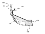
- FIG. 1 is a view for explaining the above-mentioned problem in more detail, and is a longitudinal sectional view showing the periphery of an inclined portion connected to a floor panel in a dash panel.
- the sound absorbing material 101 is mounted along the dash panel 102, and shock absorption is performed to absorb a shock at the time of a car collision on a region where a passenger's foot in the passenger compartment is placed below the sound absorbing material 101.
- a material 103 is placed.
- the shock absorber 103 has conventionally been provided with a recess 104 as a stealer for weight reduction, but the noise 106 that has entered the vehicle interior via the floor panel 105 is a gap between the sound absorbing material 101 and the recess 104. Sound leakage will occur.
- Noise generated outside the passenger compartment may enter the passenger compartment from the opening of the sound absorbing material through the space between the panel and the sound absorbing material.
- the soundproof structure for automobiles described in Patent Document 2 cannot sufficiently prevent the propagation of sound from the opening of the panel through the space between the panel and the sound absorbing material to the opening of the sound absorbing material. Further, the panel may vibrate due to engine vibration or vibration transmitted from the road surface to the vehicle body, and may generate noise. In the automobile soundproof structure disclosed in Patent Documents 1 and 2, it is not sufficiently considered to suppress panel vibration.
- the sound-absorbing and insulating structure disclosed in Patent Document 1 is reflected on the second panel layer by placing a sound-absorbing material layer having air permeability between the first panel layer and the second panel layer. It is characterized by absorbing sound when returning to one panel layer, sound leakage from gaps formed around the mounting holes formed in the sound absorbing material layer, and radiated sound due to vibration of the first panel layer The sound leakage is not fully considered.
- the present invention has been made in view of the above problems, and an object of the present invention is to provide a soundproof structure for automobiles, a fixing member for a sound absorber for automobiles, and a sound absorber that can reduce sound leakage to the passenger compartment.
- the first soundproof structure for an automobile includes a panel separating the interior and exterior of the vehicle interior, a sound absorbing material disposed along a surface of the panel on the vehicle interior side, and a fixing member for sandwiching the sound absorbing material between the panels. ,have.
- the sound absorbing material includes an opening, and has a deformed portion that is compressed and deformed by being pressed between the fixing member and the panel around the opening.
- the sound absorbing material is compressed and deformed around the opening and pressed between the part and the panel. For this reason, the sound absorbing material and the panel are in close contact with each other around the opening, and noise entering the vehicle interior from the opening is suppressed. Further, the panel is pressed against the sound absorbing material, so that the restraining effect of the panel is enhanced, the vibration generated by the panel is suppressed, and the sound leakage to the passenger compartment can be reduced.
- a second automobile soundproofing structure includes a panel that separates the exterior of the vehicle interior, a component that is positioned in the vehicle interior and is fixed to the vehicle, and a sound absorbing material that is sandwiched between the panel and the component. Have. A part of the sound absorbing material has a deformed portion that is pressed and elastically compressed by the component and the panel.
- the first sound absorbing material according to the present invention is a sound absorbing material attached to the panel, and interferes with a counterpart component attached to the panel via the sound absorbing material in the attached state attached to the panel.
- the second sound absorbing material according to the present invention is a sound absorbing material on which a component having a recessed portion is placed on the surface, and in a state where the component is placed so as to contact the surface having the recessed portion. And a convex portion provided at a position facing the concave portion on the surface in contact with the component.
- FIG. 1 is an external view of a soundproof structure for automobiles according to a first embodiment of the present invention.
- FIG. 3 is a schematic cross-sectional view of the automobile soundproof structure taken along line AA in FIG. 2. It is the perspective view and top view of an integrated fixing member. It is typical sectional drawing which shows other embodiment of the soundproof structure for motor vehicles. It is the perspective view and top view of a bipartite type fixing member. It is an external view of the soundproof structure for motor vehicles based on the 2nd Embodiment of this invention.
- FIG. 8 is a schematic cross-sectional view of the automobile soundproof structure taken along line AA in FIG. 7.
- FIG. 8 is a schematic cross-sectional view of the automobile soundproof structure taken along line BB in FIG. 7.
- FIG. 8 is a schematic cross-sectional view of a vehicle soundproof structure taken along the line CC of FIG. 7. It is a conceptual diagram which shows the positional relationship of a deformation
- FIG. 19 is a cross-sectional view taken along line AA in FIG.
- FIG. 19 is a sectional view taken along line BB in FIG.
- FIG. 19 is sectional drawing which shows the sound-absorbing material of the 3rd Embodiment of this invention.
- It is sectional drawing which shows the sound-absorbing material of the modification of the 3rd Embodiment of this invention.
- FIG. 19 is a cross-sectional view taken along the line CC of FIG. It is the figure which remove
- FIG. 27 is an example of a cross-sectional view taken along line BB in FIG. 26.
- FIG. 27 is an example of a cross-sectional view taken along the line CC of FIG. 26.
- the vehicle soundproof structure 1 described in the following embodiments can be generally applied to a vehicle soundproof structure.
- a dash panel 20 that partitions an engine room and a vehicle compartment in front of the vehicle and a dash panel 20.
- the sound-absorbing material 10 (dash silencer) to be mounted on will be described as an example.
- FIG. 2 is a perspective view showing the overall configuration of the sound absorbing material 10 attached to the dash panel 20 of the automobile.
- FIG. 1 is a view of the sound absorbing material 10 viewed from the passenger compartment side, with the left side corresponding to the left front seat of the vehicle and the right side corresponding to the right front seat of the vehicle.
- the dash panel 20 is disposed substantially vertically.
- the sound absorbing material 10 is attached to the dash panel 20 along the surface of the dash panel 20 on the passenger compartment side.
- the sound absorbing material 10 is provided between the dash panel 20 and a component (not shown).
- the component is mounted on a panel such as an air conditioner unit, an instrument panel, or a duct, for example.
- the sound absorbing material 10 is covered with these components and cannot be visually recognized from the passenger compartment.
- the sound-absorbing material 10 is a member having a sound-proofing function that blocks or absorbs sound (noise) transmitted from outside the vehicle compartment, and a vibration-damping function that suppresses vibration generated in the dash panel 20 and parts.
- the dash panel 20 is provided with a plurality of openings 20a through which air-conditioner ducts, wire harnesses, steering shafts, and the like penetrate, and the sound absorbing material 10 is also provided with openings 10a corresponding thereto.
- the sound absorbing material 10 is formed with an opening 10b for fixing the sound absorbing material 10 to the dash panel 20 (see FIG. 3).
- a stud 40 is attached to the surface of the dash panel 20 on the passenger compartment side.
- the opening 10 b of the sound absorbing material 10 is passed through the stud 40, and the fixing member 30 is engaged with the stud 40. Thereby, the sound absorbing material 10 is fixed to the dash panel 20.
- the material of the sound absorbing material 10 foams made of various soft resins and fiber molded bodies made of non-woven fabrics are suitably used, and a particularly preferred material is a foam of soft urethane resin.
- the sound-absorbing material 10 preferably has a density of 0.01 g / cm 3 to 0.1 g / cm 3 and a hardness of 25 N to 650 N (evaluation method JIS K K 6400-2), more preferably 150 to 400 N. In the present invention, the hardness of the sound absorbing material 10 is particularly important.
- the hardness is smaller than the above numerical range (if it is soft), the rigidity of the entire sound absorbing material 10 is insufficient, so that the mounting property of the sound absorbing material 10 to the dash panel 20 may be deteriorated, and the hardness is larger than the above numerical range. And (if it is hard) the required vibration damping performance for the dash panel 20 cannot be obtained, and / or the elastic repulsion of the sound absorbing material 10 when a part of the sound absorbing material 10 is deformed by a fixing member 30 or a part to be described later. Since the force becomes too strong, there is a possibility that mounting failure of the fixing member 30 or parts or deterioration of mounting workability may be a problem.
- the shape and size of the sound absorbing material 10 are determined by the shape and size of the dash panel 20 on which the sound absorbing material 10 is provided.
- the shape of the sound absorbing material 10 in the mounted state is a horizontally long and substantially rectangular shape
- the width (length in the horizontal direction) is 900 mm to 1800 mm
- the height (length in the vertical direction) is 400 mm to 1200 mm. It is.
- FIG. 3 shows a schematic cross-sectional view along the line AA in FIG.
- a stud 40 for fixing the sound absorbing material 10 is provided on the surface 20b of the dash panel 20 on the passenger compartment side.
- the stud 40 is fixed to the dash panel 20 by welding.
- the stud 40 has a cylindrical shape as a whole, and a central axis 40 a extends perpendicularly to the surface 20 b of the dash panel 20 on the passenger compartment side.
- On the surface of the stud 40 On the surface of the stud 40, a plurality of grooves 40c extending in the circumferential direction in parallel to each other are formed.
- the stud 40 extends from the passenger compartment side surface 20b of the dash panel 20 and passes through an opening 10b provided in the sound absorbing material 10.
- the automobile soundproof structure 1 has a fixing member 30.
- the fixing member 30 holds the sound absorbing material 10 between the dash panel 20.
- 4A is a perspective view of the fixing member 30 as viewed from the passenger compartment side
- FIG. 4B is a perspective view of the fixing member 30 as viewed from the dash panel side
- FIG. 4C is a perspective view as viewed from the passenger compartment side.
- the gap defining member 33 on the back side of the flange 32 and the opening 10b of the sound absorbing material 10 are indicated by broken lines.
- the fixing member 30 has a cylindrical portion 31, a flange 32, and an interval defining member 33.
- the fixing member 30 is integrally formed of a material such as resin or metal.
- the cylindrical portion 31 has a hollow cylindrical shape coaxial with the stud 40, and extends around the stud 40.
- a locking portion 34 having a claw shape protruding from the inner side surface 31a is provided on the inner side surface 31a of the cylindrical portion 31, a locking portion 34 having a claw shape protruding from the inner side surface 31a is provided on the inner side surface 31a of the cylindrical portion 31, a locking portion 34 having a claw shape protruding from the inner side surface 31a is provided.
- the locking portion 34 extends obliquely from the inner side surface 31 a of the cylindrical portion 31 toward the central axis 31 b of the cylindrical portion 31 in a direction away from the dash panel 20.
- Four locking portions 34 are provided at equal intervals in the circumferential direction.
- the flange 32 has a flat plate shape having an opening 32 a, and the opening 32 a coincides with the inner space of the cylindrical portion 31.
- the flange 32 is attached to the end of the cylindrical portion 31 on the dash panel 20 side in a direction orthogonal to the central axis 31 b of the cylindrical portion 31.
- the flange 32 has a larger outer shape than the opening 10 b of the sound absorbing material 10, and its outer peripheral portion overlaps with the sound absorbing material 10 when attached.
- the space defining member 33 is fixed to the surface of the flange 32 on the dash panel 20 side, and extends parallel to the central axis 31 b of the cylindrical portion 31. As shown in FIG.
- the interval defining member 33 is four ribs arranged at equal intervals around the opening 32a of the flange 32.
- the interval defining member 33 extends through the opening 10 b of the sound absorbing material 10 and contacts the dash panel 20 to define the interval between the flange 32 and the dash panel 20.
- the opening 10b of the sound-absorbing material 10 can take any shape as long as the stud 40 and the interval defining member 33 can be accommodated. In the example shown in FIG.
- the opening 10b of the sound absorbing material 10 has a circular shape with a diameter larger than that of the stud 40 as a whole, and a slit 10c extending in the radial direction is provided at a portion through which the interval defining member 33 passes.
- the sound absorbing material 10 can be assembled to the dash panel 20 so that the circular edge of the opening 10 b abuts against the stud 40. It is preferable because the fixing member 30 can be attached in a state where the position of the sound absorbing material 10 is regulated by the stud 40.
- the opening 10b of the sound-absorbing material 10 is circular shape as a whole, and the slit 10c is not provided.
- the opening 10 b has a diameter that can accommodate the space defining member 33.
- This example is preferable in that the fixing member 30 can be attached at any rotation angle.
- the cylindrical portion 31 is positioned with respect to the stud 40 so that the cylindrical portion 31 and the central axes 31b and 40a of the stud 40 coincide.
- the fixing member 30 is pushed toward the dash panel 20 until the distance defining member 33 contacts the dash panel 20.
- the flange 32 compresses and deforms the sound absorbing material 10 around the opening 10b (note that the broken line in FIG. 3 shows the outer shape of the sound absorbing material 10 before being compressed and deformed).
- the fixing member 30 is pushed in the direction away from the dash panel 20 by the elastic repulsive force of the sound absorbing material 10, but is fixed to the stud 40 by the locking portion 34 being locked in the groove 40 c of the stud 40.
- the deformed portion 12 that is pressed and compressed and deformed between the fixing member 30 and the dash panel 20 is formed around the opening 10 b of the sound absorbing material 10.
- the thickness of the sound absorbing material 10 is preferably 10 mm to 120 mm, particularly preferably 20 mm to 80 mm. If the thickness of the sound absorbing material 10 is smaller than the above numerical range, it is difficult to ensure sound absorption, and if the thickness is larger than the above numerical range, the sound absorbing material 10 is disposed along the dash panel 20 due to insufficient flexibility. Becomes difficult.
- the thickness of the sound absorbing material 10 is constant, but may vary depending on the location.
- the conventional sound absorbing material is attached to the dash panel without being pressed. For this reason, depending on the dimensional accuracy and mounting accuracy of the sound absorbing material, the sound absorbing material is separated from the dash panel, and engine noise and road noise tend to enter the vehicle interior through the gap between the dash panel and the sound absorbing material.
- the sound absorbing material 10 is elastically compressed by the deformable portion 12 and is brought into close contact with the dash panel 20. Since the deformed portion 12 is continuously provided along the opening 10b of the sound absorbing material 10 in which vibration is likely to enter from the outside of the vehicle compartment, it enters the vehicle interior from the opening 10b through the gap between the dash panel 20 and the sound absorbing material 10. Engine noise and road noise are effectively shielded. Moreover, since the dash panel 20 is restrained by the elastic repulsive force of the compressed sound absorbing material 10, vibration of the dash panel 20 is suppressed.
- the compressibility of the deformed portion 12 of the sound absorbing material 10 is preferably 0% to 80% (excluding 0%) with respect to the thickness of the sound absorbing material 10, and particularly preferably 20% to 40%. If the compression ratio of the deformable portion 12 is smaller than the above numerical range, the repulsive force may be insufficient, and sufficient vibration damping performance may not be obtained. The compressibility of the deformable portion 12 is more than the above numerical range. If it is large, the interference with the dash panel 20 and the fixing member 30 becomes excessively strong, and there is a risk that attachment property will be lowered and attachment problems will occur.
- the thickness of the deformed portion 12 of the sound absorbing material 10 can be formed with high accuracy.
- the compressive deformation of the deformable portion 12 is insufficient, the sound absorbing material 10 does not sufficiently adhere to the dash panel 20, and noise entering from the opening 10 b of the sound absorbing material 10 cannot be effectively blocked. If the deformable portion 12 is excessively compressed, the sound absorbing property of the sound absorbing material 10 is lowered, or the load when the sound absorbing material 10 is compressed by pushing the fixing member 30 becomes too high and the mounting workability is lowered. There is.
- the thickness of the deformed portion 12 of the sound absorbing material 10 is likely to vary without the spacing defining member 33.
- the thickness of the deformed portion 12 of the sound absorbing material 10 is substantially equal to the distance between the flange 32 and the dash panel 20 defined by the distance defining member 33. Accordingly, the fixing member 30 is pushed toward the dash panel 20 so that the tip of the interval defining member 33 contacts the dash panel 20, and the state is fixed by the locking portion 34, whereby the deformed portion 12 of the sound absorbing material 10 is obtained. Variation in the thickness of the substrate is reduced.
- FIG. 5 and 6 show other examples of the fixing member.
- the fixing member 50 in this example includes a first portion 51 and a second portion 52.
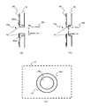
- FIG. 5 shows a schematic cross-sectional view along the line AA of FIG.
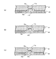
- FIG. 5A shows a state before the sound absorbing material 10 is attached to the dash panel 20
- FIG. 5B shows a state after the sound absorbing material 10 is attached to the dash panel 20.
- 6A is a perspective view of the first portion 51 as viewed from the passenger compartment side
- FIG. 6B is a perspective view of the first portion 51 as viewed from the dash panel side
- FIG. 6D shows a perspective view of the second portion 52 viewed from the passenger compartment side
- 6D shows a perspective view of the second portion 52 viewed from the dash panel side.
- 6 (e) is a perspective view of the assembled fixing member 50 as viewed from the passenger compartment side
- FIG. 6 (f) is a perspective view of the assembled fixing member 50 as viewed from the dash panel side.
- FIG. 6G is a plan view of the assembled fixing member 50 viewed from the passenger compartment side
- FIG. 6H is a plan view of the assembled fixing member 50 viewed from the dash panel side.
- the first portion 51 has a first flange 53 and a first cylindrical portion 54.
- the first flange 53 has a flat plate shape having an opening 53a.
- the first cylindrical portion 54 has a hollow cylindrical shape coaxial with the stud 40, and extends around the stud 40.
- a locking portion 55 having a claw shape protruding from the inner side surface of the first cylindrical portion 54 is provided inside the first cylindrical portion 54.
- the first cylindrical portion 54 is located on the dash panel 20 side of the first flange 53.
- a claw portion 56 that extends radially outward from the first cylindrical portion 54 and holds the second portion 52 is provided at the tip of the first cylindrical portion 54 on the dash panel 20 side.
- the claw portions 56 are provided at two positions 180 degrees apart from each other (see FIG. 6B), but the shape and number are not limited to this.
- the second portion 52 includes a second cylindrical portion 57 that engages with the first portion 51, a second flange 58 that sandwiches and compresses the sound absorbing material 10 together with the first flange 53, and a second cylindrical portion. And a connecting portion 59 for connecting 57 to the second flange 58.
- the second cylindrical portion 57 is held between the first flange 53 and the claw portion 56.
- the diameter of the first flange 53 is preferably larger than the diameter of the second flange 58.
- the fixing member 50 is first attached to the sound absorbing material 10 as shown in FIG.
- the second portion 52 is connected to the sound absorbing material 10 from the opposite side of the sound absorbing material 10. Is inserted into the opening 10 b of the sound absorbing material 10.
- the second cylindrical portion 57 of the second portion 52 is engaged with the claw portion 56 of the first flange 53, and the state where the sound absorbing material 10 is compressed with a predetermined thickness is maintained.
- the 1st part 51 and the 2nd part 52 are integrated by this, and the fixing member 50 is formed.
- the sound absorbing material 10 to which the fixing member 50 is attached is attached to the dash panel 20. That is, the sound absorbing material 10 is positioned so that the stud 40 passes inside the first cylindrical portion 54, and the first portion 51 is pressed toward the dash panel 20. The deformable portion 12 of the sound absorbing material 10 gradually moves toward the dash panel 20. When the tip of the first cylindrical portion 54 or the second flange 58 contacts the dash panel 20, the fixing member 50 can no longer be pushed. The locking portion 55 is locked in the groove of the stud 40, and this state is maintained.
- the first cylindrical portion 54 or the second flange 58 has a function of a space defining member.
- the tip of the first cylindrical portion 54 and the surface of the second flange 58 on the dash panel 20 side are substantially aligned, but either one may protrude from the other to the dash panel 20 side. In that case, the member protruding to the dash panel 20 side has a function of the interval defining member.
- the fixing member 50 is fixed to the sound absorbing material 10 in advance, the process of attaching the sound absorbing material 10 to the dash panel 20 can be simplified. That is, in the first example, the sound absorbing material 10 is arranged and then the fixing member 30 is attached, whereas in this example, the sound absorbing material 10 to which the fixing member 50 is attached only needs to be attached to the dash panel 20. Therefore, there is no risk of the fixing member 30 being lost during the mounting process of the sound absorbing material 10.
- FIG. 7 is a perspective view showing the overall configuration of the sound absorbing material 10 attached to the dash panel 20 of the automobile in the second embodiment.
- the positions of the openings 10 a and the like are different from those in the first embodiment shown in FIG. 2.
- a stud 40 is attached to the surface of the dash panel 20 on the passenger compartment side, and the sound absorbing material 10 has an opening 10 a and a notch 10 c. Is formed.
- the stud 40 is passed through the opening 10 b and the notch 10 c of the sound absorbing material 10, and a fixture (not shown) such as a clip or a nut is locked to the stud 40. Thereby, the sound absorbing material 10 is fixed to the dash panel 20.
- the parts are fixed to the dash panel 20 by an appropriate method and fixed to the vehicle.
- a stud 40 is attached to the surface of the dash panel 20 on the passenger compartment side, and the sound absorbing material 10 has an opening 10b and a notch 10c.
- the stud 40 is passed through the opening 10 b and the notch 10 c of the sound absorbing material 10, and a fixture (not shown) such as a clip or a nut is locked to the stud 40.
- a fixture such as a clip or a nut is locked to the stud 40.
- the sound absorbing material 10 is fixed to the dash panel 20.
- a suitable example of the material of the sound absorbing material 10 is the same as in the first embodiment. If the hardness of the sound absorbing material 10 is smaller than the numerical range shown in the first embodiment, the rigidity of the sound absorbing material 10 as a whole is insufficient, so that the mounting property of the sound absorbing material 10 to the vehicle may be deteriorated. If the hardness is larger than the above numerical range (if it is hard), the required vibration damping performance for the panel may not be obtained, and when a part of the sound absorbing material 10 is elastically compressed by the component 30a, the sound absorbing material The elastic repulsive force of 10 becomes too strong, and there is a possibility that component mounting failure or mounting workability may deteriorate.
- the shape and size of the sound absorbing material 10 are the same as those in the first embodiment.
- the lower part of the sound absorbing material 10 is covered with an impact absorbing material 41.
- the shock absorber 41 is disposed in a lower part of the sound absorbing material 10, more specifically, in a region where the sound absorbing material 10 and the floor carpet are in contact with each other.
- the front part of the shock absorbing material 41 is placed on the sound absorbing material 10, and the rear part is installed on the floor panel.
- a floor carpet (not shown) is laid on the upper surface of the shock absorber 41, and the shock absorber 41 cannot be seen from the passenger compartment. As a result, the appearance and appearance of the passenger compartment are kept good.
- the shock absorbing material 41 is formed of a foamed material made of polypropylene (PP), polystyrene (PS), urethane, or the like.
- the shock absorber 41 is placed on the floor panel without using a fixture, but may be fixed to the floor panel with a fixture such as a clip.
- the shock absorber 41 may be incorporated in a peripheral part such as a floor carpet and the peripheral part to which the shock absorber 41 is attached may be fixed to a floor panel or the like.
- the shock absorbing material 41 is provided in each of the left front seat and the right front seat of the vehicle, and a floor tunnel 42 is provided between them.
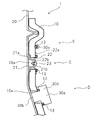
- FIG. 8 shows a schematic cross-sectional view along the line AA in FIG.
- the protrusion 13 described below is compressed by the component 30a at the time of mounting, but for convenience, the protrusion 13 in an uncompressed state is shown superimposed on the component 30a (the same applies to FIGS. 13 and 14).
- the overlapping part is hatched.
- the dash panel 20 and the sound absorbing material 10 have openings 20a and 10a, respectively, and a component 30a is attached to the dash panel 20 so as to cover these openings 20a and 10a. .
- the component 30a is fixed to the vehicle.
- the component 30 a is passed through the stud 40 attached to the dash panel 20, and the nut 43 is fastened to the stud 40.
- the component 30a is an air conditioner unit, but is not limited thereto, and any component may be used as long as the sound absorbing material 10 is sandwiched between the component 30a and the dash panel 20.
- a convex portion (projection) 13 is provided on the surface 10 d of the sound absorbing material 10 on the passenger compartment side, that is, on the surface opposite to the dash panel 20 of the sound absorbing material 10.
- the convex portion 13 is integrally formed with a constant thickness portion (hereinafter referred to as a main body 14) of the sound absorbing material 10, but may be fixed to the main body 14 by an adhesive, fusion, or the like.
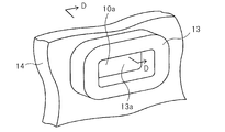
- FIG. 9 shows a perspective view of the convex portion 13.
- the convex portion 13 includes a central opening that substantially coincides with the opening 20 a of the dash panel 20 and the opening 10 a of the main body 14 of the sound absorbing material 10, and is provided along the entire circumference of the peripheral portion of the opening 10 a of the main body 14 of the sound absorbing material 10. Yes.
- the convex portion 13 may be provided partially or intermittently along the peripheral edge portion of the opening 10 a of the main body 14 of the sound absorbing material 10.
- the component 30a is attached to the dash panel 20 so as to press the convex portion 13.
- the convex portion 13 of the sound absorbing material 10 and its periphery are elastically compressed.
- the other parts of the sound absorbing material 10 are not elastically compressed by the component 30a.
- a portion of the sound absorbing material 10 that deforms by interfering with at least one of the component 30a and the dash panel 20 between the component 30a and the dash panel 20 (for example, a portion that is pressed and elastically compressed). ) Is called the deforming portion 12, and the other portion is called the general portion 11.
- the deformation portion 12 includes a convex portion 13 of the sound absorbing material 10 that is pressed by the component 30a.
- the surface of the sound absorbing material 10 opposite to the convex portion 13 is in contact with the dash panel 20.
- the general portion 11 of the sound absorbing material 10 may be in contact with the dash panel 20 or may be separated from the dash panel 20.
- the thickness of the general portion 11 of the sound absorbing material 10 is the same as the thickness of the sound absorbing material 10 of the first embodiment.
- the thickness of the convex portion 13 of the sound absorbing material 10 is preferably 1 mm to 30 mm, and particularly preferably 5 mm to 20 mm.
- the amount of compression of the convex portion 13 (the amount of change in thickness due to pressing of the component 30a) is preferably 0 mm to 10 mm (excluding 0 mm), and particularly preferably 2 mm to 6 mm. If the amount of compression of the convex portion 13 is smaller than the above numerical range, the elastic repulsion force is insufficient and sufficient vibration damping performance cannot be obtained. When the compression amount is larger than the above numerical range, the elastic repulsion force becomes too large, and the attachment property is liable to be deteriorated or malfunctioned.
- the conventional sound absorbing material is attached without being pressed by the dash panel and the parts. For this reason, depending on the dimensional accuracy and mounting accuracy of the sound absorbing material, the sound absorbing material is separated from the component, and engine noise and road noise tend to enter the vehicle interior through the gap between the sound absorbing material and the component.
- the deformable portion 12 of the sound absorbing material 10 has the convex portion 13 and is thicker than the general portion 11. For this reason, the sound-absorbing material 10 is elastically compressed by the deformable portion 12, and is firmly attached to the dash panel 20 and the component 30a.
- the convex portion 13 is continuously provided along the opening 10a of the sound absorbing material 10 in which vibration is likely to enter from outside the vehicle compartment, the engine that enters the vehicle interior through the gap between the opening 10a of the sound absorbing material 10 and the component 30a. Noise and road noise are effectively shielded. In addition, since the dash panel 20 and the component 30a are restrained by the elastic repulsive force of the compressed sound absorbing material 10, these vibrations are suppressed.
- the convex portion 13 is locally formed (that is, the sound absorbing material 10 is locally thickened), the mounting property of the component 30a to the dash panel 20 or the vehicle can be improved.
- the sound absorbing material is formed thick on the entire surface, the sound absorbing material is compressed on the entire surface.
- the elastic repulsion force received by the component 30a from the sound absorbing material increases, and the load required for mounting the component 30a increases, and the possibility that workability deteriorates increases.
- the convex part 13 since the convex part 13 is formed locally, the elastic repulsive force of the sound-absorbing material 10 is limited. Therefore, it is possible to improve the vibration damping performance without deteriorating the mounting property of the component 30a.
- the sound absorbing material 10 is reliably pressed between the dash panel 20 and the component 30a even if the dimensions and positioning accuracy of the sound absorbing material 10 and the component 30a vary. For this reason, it becomes possible to reliably provide the soundproofing performance of the sound absorbing material 10 and the vibration damping performance for the dash panel 20 and the component 30a.
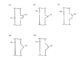
- FIG. 10A shows a cross-sectional shape of the convex portion 13 along the line DD in FIG.
- the cross-sectional shape of the convex portion 13 is a rectangular or square shape.
- the cross-sectional shape of the convex portion 13 is a trapezoidal shape shown in FIG. 10 (b), a rectangular shape with rounded tip corners shown in FIG. 10 (c), a triangular shape with rounded tops shown in FIG. 10 (d),
- a semicircular shape shown in FIG. 10E can also be used.
- the convex portion 13 shown in FIGS. 10B to 10E has a tapered cross section whose width gradually decreases toward the tip. For this reason, the strength of the convex portion 13 is increased, the possibility that the convex portion 13 is broken is reduced, the moldability is enhanced, and the possibility of occurrence of molding defects such as a defect of the convex portion 13 is reduced.
- the convex part 13 is provided on the sound absorbing material 10 even when the component 30 a is fixed at a position where the opening 20 a of the dash panel 20 is not present.
- the component 30a is fixed to the vehicle by fixing means (not shown).
- the convex portion 13 is pressed and elastically compressed between the component 30a and the dash panel 20. Since the sound absorbing material 10 restrains the dash panel 20 and the component 30a, the vibration damping effect on the dash panel 20 and the component 30a is enhanced.
- the convex part 13 in the B part of FIG. 8 has a shape with a concave part 13a as shown in FIG.
- a contact part between the convex part 13 and the part 30a is provided along the outer edge of the part 30a.
- the component 30a can be reliably restrained in a wider range, so that the vibration damping effect on the component 30a is enhanced.
- the concave portion 13a is provided, the contact area between the convex portion 13 and the component 30a does not increase greatly. For this reason, the elastic repulsive force of the sound-absorbing material 10 is limited, and it becomes possible to improve the mounting property. As a result, it is possible to achieve both vibration control effects and mounting properties that are mutually contradictory.
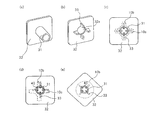
- FIG. 11 shows another embodiment applicable to the convex portion 13 of the B portion.
- the convex portion 13 is a set of a plurality of convex portions arranged at intervals shown in FIG. 11 (a), a cross shape shown in FIG. 11 (b), an X shape shown in FIG. 11 (c), and FIG. 11 (d).
- FIG. 12 shows still another aspect applicable to the convex portion 13 of the B portion.
- the convex portion 13 is a rectangular parallelepiped as shown in FIG. 12 (a), a cylindrical shape (disc shape) as shown in FIG. 12 (b), a rectangular parallelepiped shape with rounded corners as shown in FIG. 12 (c), and FIG. 12 (d).
- the frustum shape shown may be sufficient. Also in these aspects, if the contact area of the component 30a and the convex part 13 is enlarged, the restraining effect with respect to the dash panel 20 and the component 30a is improved.
- FIG. 13 shows a cross-sectional view along the line BB in FIG.
- no opening is provided in the dash panel 20, and an opening 10 a is provided only in the sound absorbing material 10.
- a first fixing member 21 and a second fixing member 22 that faces the first fixing member 21 are provided in the opening 10a.
- the base portion 21a of the first fixing member 21 is welded to the surface of the dash panel 20 on the passenger compartment side.
- the first fixing member 21 has a first top plate 21b protruding toward the passenger compartment.
- the second fixing member 22 has a base portion 22a and a second top plate 22b drawn from the passenger compartment side.
- the first top plate 21 b and the second top plate 22 b face each other and are fixed to each other with bolts or screws 23.
- the sound absorbing material 10 is sandwiched between the base portion 21 a of the first fixing member 21 and the base portion 22 a of the second fixing member 22.
- a rib-like convex portion 13 surrounding the opening 10a is formed at an edge portion along the opening 10a of the sound absorbing material 10, that is, at a contact portion with the base portion 22a of the second fixing member 22 of the sound absorbing material 10.
- the convex portion 13 is compressed between the base portion 21 a of the first fixing member 21 and the base portion 22 a of the second fixing member 22, and from the gap between the base portion 22 a of the second fixing member 22 and the sound absorbing material 10. Prevents noise entering the passenger compartment.
- the convex portion 13 has the same shape as that shown in FIG. 9, and can have various cross-sectional shapes shown in FIG.
- the same configuration is possible when the component 30a is fixed to the dash panel 20 through the opening 10a of the sound absorbing material 10 as shown in the D part of FIG. That is, the component 30 b of the component 30 a is fixed to the dash panel 20, and the sound absorbing material 10 is sandwiched between the flange portion 30 c of the component 30 a and the dash panel 20.
- the component 30a is fixed to the vehicle by fixing means (not shown).
- the distance between the component 30b of the component 30a and the flange part 30c is constant, it is not restricted to this, It is good also as a shape along the shape of the sound-absorbing material 10.
- a rib-like convex portion 13 surrounding the opening 10a is formed at an edge portion along the opening 10a of the sound absorbing material 10, that is, at a contact portion between the sound absorbing material 10 and the flange portion 30c of the component 30a.
- the convex portion 13 is compressed between the dash panel 20 and the flange portion 30c of the component 30a, and prevents noise entering the vehicle interior from the gap between the flange portion 30c of the component 30a and the sound absorbing material 10.
- the convex portion 13 has the same shape as that shown in FIG. 9, and can have various cross-sectional shapes shown in FIG.
- the component 30 a may not be directly fixed to the dash panel 20.
- a vibration damping effect can be obtained in the same manner by compressing the sound absorbing material 10 with a component 30a that is fixed at a predetermined position in the passenger compartment, such as an electrical component such as a harness.
- the convex part 13 can take various cross-sectional shapes shown in FIGS.
- FIG. 14 is a sectional view taken along the line CC of FIG.
- the dash panel 20 is provided with a fixing portion (stud 40) for fixing the sound absorbing material 10.
- the stud 40 is welded to the dash panel 20.
- the stud 40 passes through the opening 10 b provided in the sound absorbing material 10.
- the claw 61 of the clip 60 is locked in the groove of the stud 40, and the sound absorbing material 10 is fixed to the dash panel 20.
- the convex portion 13 of the sound absorbing material 10 is provided on the surface on the dash panel 20 side. That is, the deformable portion 12 includes a convex portion 13 provided at a contact portion between the sound absorbing material 10 and the dash panel 20.
- the deformable portion 12 is provided between the two studs 40.
- the sound absorbing material 10 is supported by the dash panel 20 in a vertical direction or a posture close thereto as shown in FIG. 7, the sound absorbing material 10 is easily separated from the dash panel 20 at a position between the two studs 40. Since the convex portion 13 presses the dash panel 20 even when the sound absorbing material 10 moves away from the dash panel 20, in addition to the vibration damping effect of the dash panel 20 by the stud 40, the vibration damping effect is also provided at a position where the stud 40 is not present. Occurs.
- the deformed portion 12 provided with the convex portion 13 is closer to the center of the deformed portion 12 than the center distance L between the two studs 40a and 40b closest to the center of the deformed portion 12. It is preferable that the distances L1 and L2 to the centers of the studs 40a and 40b are shorter and are provided within the hatched range in the figure. More preferably, the deformable portion 12 is provided within a range surrounded by two arcs 44a and 44b, as shown in FIG.
- each of the two arcs 44a and 44b passes through the two studs 40a and 40b with the center-to-center distance L between the two studs 40a and 40b closest to the center of the deformable portion 12 as a radius.
- the convex portion may be formed on the dash panel 20 or the component 30 a instead of the sound absorbing material 10.
- FIG. FIG. 16 is a modification of the embodiment shown in FIG. In the present modification, a convex portion 24 is formed on the dash panel 20. In the example shown in FIG. 16A, the convex portion 24 is integrally formed with the dash panel 20. As shown in FIG. 16 (b), the convex portion 24 may be welded to the dash panel 20 with a convex reinforcement 25 separate from the dash panel 20, or as shown in FIG. The stud 20 may be welded to the panel 20.
- the deformed portion 12 can also be formed by forming a convex portion on the surface of the clip 60 on the sound absorbing material 10 side and pressing the clip 60 against the sound absorbing material 10. That is, the deformable portion 12 is provided at a contact portion of the dash panel 20 or the clip 60 (more generally, the component 30a fixed to the vehicle) with the sound absorbing material 10, and the deformable portion 12 of the sound absorbing material 10 is provided.
- the convex part which presses may be sufficient.
- the clip 60 is pushed into the stud 40 until the distance between the clip 60 and the dash panel 20 becomes substantially equal to the thickness of the sound absorbing material 10, and is locked to the stud 40. Further, the sound absorbing material 10 may be elastically compressed by pushing the clip 60. With such a configuration, the vibration control performance is further improved.
- the sound-absorbing material 10 should just have the deformation
- transformation part 12 which was pressed between the components 30a and the dash panel 20, and was elastically compressed.
- FIG. 18 is a perspective view showing the overall configuration of the sound absorbing material 10 attached to the dash panel 20 of the automobile in the third embodiment.
- the automobile soundproof structure 1 shown in FIG. 18 is a dash panel 20 that is a partition wall that separates a vehicle compartment from an engine room, a sound absorbing material (dash silencer) 10 that is attached to the dash panel 20, and a car floor. And an impact absorbing material (tibia pad) 41 attached on the floor panel. Further, an opening 10a and a notch 10c of the sound absorbing material (dash silencer) 10 are shown.
- the sound absorbing material 10 is attached to the dash panel 20 by, for example, hooking the opening 10 a and the notch 10 c on a protrusion such as a bolt fixed to the dash panel 20. Further, the sound absorbing material 10 may be attached to the dash panel 20 by a fixture such as a clip or a bolt, or a component such as an air conditioner unit or an instrument panel.
- FIG. 19 is a cross-sectional view taken along line AA of the automobile soundproof structure 1 shown in FIG. 18, and FIG. 20 is a cross-sectional view taken along line BB of the vehicle soundproof structure 1 shown in FIG. is there.
- the sound absorbing material 10 is deformed by interfering with at least one of the component 30 a and the dash panel 20 in the mounted state attached to the dash panel 20, and other portions. And a non-deformable general part 11.
- transformation part 12 By having the deformation
- the sound absorbing material 10 has a substantially constant thickness when not attached to the dash panel 20, and the deformation portion 12 of the sound absorbing material 10 is attached to the dash panel 20. In the mounted state, the component 30a is compressed in the thickness direction.
- transformation part 12 is not restricted to this example. Note that the material, outer shape, size, and the like of the sound absorbing material 10 are the same as those in the first and second embodiments.
- FIG. 21 is a diagram showing the characteristics of the sound absorbing material 10 of the third embodiment. Specifically, FIG. 21A is a partial longitudinal sectional view of the sound absorbing material 10 in the non-attached state, FIG. 21B is a partial longitudinal sectional view of the sound absorbing material 10 in the attached state, and FIG. It is a partial front view of the sound-absorbing material 10 in a non-attached state.
- the 21 has an opening 10a which is an attachment hole for attaching the component 30a via the sound absorbing material 10, and a slit 10a1 formed so as to surround the opening 10a.
- the component 30a is brought into contact with one region on both sides of the slit 10a1 (specifically, the region on the side where the opening 10a exists), and the contacted region becomes the deformed portion 12 and is crushed by the component 30a. Is done.
- the slit 10a1 becomes a gap filling structure portion that fills the gap between the dash panel 20 and the component 30a using the deformable portion 12 in the attached state.
- one of the regions on both sides of the slit 10a1 is crushed by the component 30a so that the sound absorbing material 10 adheres to the component 30a, and the gap between the sound absorbing material 10 and the component 30a is filled. , And can be dressed with a small repulsive force. Moreover, the dash panel 20 will be pushed down when the sound-absorbing material 10 is crushed, and the vibration damping performance of the dash panel 20 can be improved.
- FIG. 22 is a diagram illustrating the characteristics of the sound absorbing material 10 according to a modification of the third embodiment. Specifically, FIG. 22A is a partial longitudinal sectional view of the sound absorbing material 10 in the non-attached state, and FIG. 22B is a partial longitudinal sectional view of the sound absorbing material 10 in the attached state. ) Is a partial front view of the sound absorbing material 10 in a non-attached state.
- the 22 has a slit 10a2 in addition to the slit 10a1 as a gap filling structure.
- the slit 10a2 exists in a region on the opposite side of the region where the opening 10a is present, from both regions sandwiching the slit 10a1.
- the slit 10a2 is formed so as to surround the opening 10a.
- the depth of the slit 10a2 is preferably deeper than the depth of the slit 10a1.
- the component 30a is brought into contact with the region on the side where the opening 10a is present on both sides of the slit 10a1, and the region between the contacted region and the slits 10a1 and 10a2 is the deformed portion 12. It becomes.
- the intermediate portion 10a3 between the slits 10a1 and 10a2 is pulled toward the component 30a and approaches the component 30a while falling down.
- the gap between the panel 20 and the component 30a can be covered with the intermediate portion 10a3. Therefore, the gap between the dash panel 20 and the component 30a can be filled more reliably, and sound leakage to the passenger compartment can be further reduced. Further, when the depth of the slit 10a2 is deeper than the depth of the slit 10a1, the intermediate portion 10a3 is likely to fall down toward the component, and the gap can be filled more reliably.
- the number of slits provided separately from the slits 10a1 may be one or more.
- Each of the slits 10a1 and 10a2 only needs to be formed around the opening 10a, and does not need to surround the opening 10a.
- FIG. 23 is a diagram illustrating characteristics of the sound-absorbing material 10 according to another modification of the third embodiment. Specifically, FIG. 23A is a partial longitudinal sectional view of the sound absorbing material 10 in the non-attached state, and FIG. 23B is a partial longitudinal sectional view of the sound absorbing material 10 in the attached state. ) Is a partial front view of the sound absorbing material 10 in a non-attached state.
- the component 30a is brought into contact with a region between the concave portion 10a4 and the opening 10a, and the contacted region becomes the deformed portion 12.
- the deformable portion 12 is bent when the component 30a is pushed into the opening 10a, and the bent portion surrounds the component 30a.
- the gap between the opening 10a and the component 30a is filled with the deformed portion 12 of the sound absorbing material 10, it is possible to suppress the component 30a from moving without the component 30a and the opening 10a being in close contact with each other. Become. Therefore, the gap between the dash panel 20 and the component 30a can be filled more reliably, and sound leakage to the passenger compartment can be further reduced.
- FIG. 24 is a sectional view taken along the line CC of the automobile soundproof structure 1 shown in FIG.
- the sound-absorbing material 10 includes a deformable portion 12 that deforms in the attached state, and a general portion 11 that is another portion.
- 24 is a component attached to the dash panel 20 or the sound absorbing material 10 such as an air conditioner unit or a duct, and the shock absorbing material 41 is also a kind of the component 30a.
- a carpet 80 is laid on the shock absorber 41. Since the sound absorbing material 10 has the deformable portion 12, it is possible to suppress the generation of a gap between the dash panel 20, the component 30a, and the sound absorbing material 10, and it is possible to effectively reduce sound leakage. become.
- the sound absorbing material 10 has a substantially constant thickness when not attached to the dash panel 20, and the deformed portion 12 of the sound absorbing material 10 is attached to the dash panel 20. In the mounted state, the component 30a is compressed in the thickness direction.
- transformation part 12 is not restricted to this example.
- the material, outer shape, and size of the sound absorbing material 10 are the same as those in the first to third embodiments.
- the amount of interference of the deformable portion 12 of the sound absorbing material 10 is preferably 0 mm to 10 mm, and particularly preferably 2 mm to 6 mm.
- the amount of interference of the deforming portion 12 is smaller than the above range, the repulsive force may be insufficient, and sufficient vibration damping performance may not be obtained, and when the amount of interference of the deforming portion 12 is larger than the above numerical range, Interference with the dash panel 20 and the component 30a becomes excessively strong, and there is a risk that the assembling property may be lowered or an assembling failure may occur.
- the shock absorber 41 includes a flat portion 71 placed on the floor panel 45 that forms a horizontal portion of the vehicle, and a slope portion placed on the inclined surface 26 that is an inclined portion connected to the floor panel 45 in the dash panel 20. 72.
- the slope portion 72 is connected to the plane portion 71 and is inclined with respect to the plane portion 71.
- the flat surface portion 71 and the slope portion 72 may be integrally molded, or may be assembled together after being individually molded. When the flat surface portion 71 and the slope portion 72 are individually molded, the physical properties such as the material and foaming ratio of the flat surface portion 71 and the slope portion 72 may be different from each other.
- the front end of the slope portion 72 protrudes upward, and the shock absorber 41 is disposed so that the lower end portion of the sound absorbing material 10 is sandwiched between the inclined surface 26 and the slope portion 72 of the dash panel 20.
- the occupant places his / her feet on the shock absorbing material 41 over the flat surface 71 and the slope 72.
- the shock absorber 41 protects the occupant's feet by absorbing the shock due to the collision by deforming and crushing the flat surface portion 71 and the slope portion 72 during the collision.
- a carpet 80 is disposed on the shock absorber 41, and a cushioning material 90 formed of felt or the like is disposed between the shock absorber 41 and the carpet 80.
- a receiving portion 73 for receiving the cushioning material 90 may be provided on the flat portion 71 of the shock absorbing material 41.
- the carpet 80 and the cushioning material 90 do not have to be arranged.
- an olefin-based or PVC (Polyvinyl Chloride) -based mat material may be disposed on the upper surface of the impact absorbing material 41.
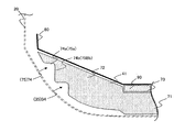
- FIG. 25A is a view for explaining the shock absorbing material 41 in more detail, and is a view in which the sound absorbing material 10 is removed from the enlarged view of the broken line portion of FIG.
- FIG. 25B is a diagram for explaining the sound absorbing material 10 in more detail, and is a diagram in which the dash panel 20 and the sound absorbing material 10 are extracted from the enlarged view of the broken line part of FIG. 24.
- the shock absorbing material 41 has a recess 74 on one surface of the slope portion 72, and is placed on the sound absorbing material 10 so that the surface having the recess 74 is in contact with the sound absorbing material 10.
- FIG. 26 is a perspective view showing the shape and position of the recess 74.
- the recess 74 has a widthwise recess 75 extending in the width direction that is substantially perpendicular to the direction of inclination of the slope 72 (the arrow direction in the figure) in the in-plane direction of the slope 72, and It includes a front-rear direction recess 76 that extends downward from both ends of the width-direction recess 75 in the front-rear direction, which is a direction substantially parallel to the direction of inclination of the slope 72.
- the recessed part 74 has comprised the substantially U shape.
- the length of the recess 75 in the width direction and the recess 76 in the front-rear direction may be longer, and it is preferable that the recess is formed near the upper end of the slope 72.
- the dent 74 may be formed from a plurality of dents.
- the recess 74 may be formed of a large substantially U-shaped recess and a small approximately U-shaped recess positioned inside the recess.
- the recess 74 of the shock absorber 41 shown in FIG. 25A has two substantially U-shaped recesses.
- the sound absorbing material 10 has the convex portion 15 at a position facing the concave portion 74 on the surface in contact with the shock absorbing material 41 in the mounting state where the shock absorbing material 41 is placed at a specified position.
- the sound absorbing material 10 has the convex portion 15 at a position facing the concave portion 74 provided on the slope portion 72 of the shock absorbing material 41.
- the convex portion 15 extends along the widthwise convex portion 16 extending along the widthwise concave portion 75 of the shock absorber 41 and the front-rear direction concave portion 76 of the shock absorber 41.
- the front-rear direction convex portion 17 the convex portion 15 at a position facing the concave portion 74 on the surface in contact with the shock absorbing material 41 in the mounting state where the shock absorbing material 41 is placed at a specified position.
- the sound absorbing material 10 has the convex portion 15 at a position facing the concave portion 74 provided on the slope portion 72 of the shock absorbing material
- the convex portion 15 is a deformed portion 12 that enters the recessed portion 74 in the mounted state and compresses and deforms by interfering with the shock absorber 41 in the recessed portion 74.
- the convex portion 15 makes it possible to improve the adhesion between the sound absorbing material 10 and the shock absorbing material 41. Therefore, it is possible to fill a gap between the sound absorbing material 10 and the shock absorbing material 41, and to reduce sound leakage to the passenger compartment.
- the convex portion 15 and the concave portion 74 are each substantially U-shaped, it is possible to reduce sound leakage in the width direction of the passenger compartment and sound leakage in the front-rear direction. Sound leakage can be further reduced.
- the dent part is formed in the plane part 71, it is preferable not to provide a convex part in the position facing the dent part. If a convex part is formed at a position facing the concave part provided in the flat part 71, the movement of the shock absorber 41 in the front-rear direction may be restricted more than necessary. In this case, a gap is generated between the sound absorbing material 10 and the inclined surface portion 72 of the shock absorbing material 41, and sound leakage may occur.
- the amount of interference between the sound absorbing material 10 and the shock absorbing material 41 is preferably 0 to 10 mm, and particularly preferably 2 to 6 mm.
- the amount of interference is 0 mm or less, the degree of adhesion between the sound absorbing material 10 and the shock absorbing material 41 cannot be ensured sufficiently, and as a result, there is a possibility that sound leakage cannot be effectively reduced.
- said interference amount is 10 mm or more, there exists a possibility that the repulsive force of the sound-absorbing material 10 may become large too much. In this case, the shock absorbing material 41 may be displaced due to the repulsive force of the sound absorbing material 10, and the shock absorbing performance of the shock absorbing material 41 may not be exhibited efficiently.
- it is difficult for an operator to assemble the shock absorber 41 and there is a risk that the efficiency of the assembling work will be reduced.
- the convex portion 15 of the sound absorbing material 10 has an interference surface 15a that abuts on the impact absorbing material 41 and is compressed and deformed, and an opposing surface 15b that is different from the interference surface 15a. It has an interference surface 74a that contacts the interference surface 15a on the convex portion 15 of the sound absorbing material 10, and a facing surface 74b that is different from the interference surface 74a.
- the interference surface 15a of the width direction convex portion 16 is referred to as an interference surface 16a
- the opposing surface 15b of the width direction convex portion 16 is referred to as an opposing surface 16b
- the interference surface 15a of the front and rear direction convex portion 17 is referred to as an interference surface 17a.
- the facing surface 15b of the front-back direction convex part 17 is called the facing surface 17b.
- the interference surface 74a of the widthwise dent 75 is referred to as an interference surface 75a
- the facing surface 74b of the widthwise dent 75 is referred to as a facing surface 75b
- the interference surface 74a of the front / rear dent 76 is referred to as an interference surface 76a.
- the facing surface 74b of the front-rear direction recess 76 is referred to as a facing surface 76b.
- FIG. 27 is a view showing a cross section taken along the line BB in FIG. 26, and is a view showing a specific example of the shape of the width direction convex portion 16 and the width direction concave portion 75.
- the widthwise dent 75 has an inner wall surface substantially parallel to the flat surface 71 of the shock absorber 41 as an interference surface 75a.
- the width direction convex part 16 has the surface substantially parallel to the plane part 71 as the interference surface 16a.
- the weight of the shock absorbing material 41 can be efficiently applied to the convex portion 16 in the width direction of the sound absorbing material 10, the degree of adhesion between the sound absorbing material 10 and the shock absorbing material 41 can be further improved. This makes it possible to further reduce sound leakage.
- the surfaces different from the surfaces substantially parallel to the flat surface portion 71 of the width direction convex portion 16 and the width direction concave portion 75 are opposed surfaces 16b and 75b that do not contact each other. In this case, it is possible to avoid that force is applied to a surface other than the interference surface substantially parallel to the flat portion 71 and the change amount of the interference surface is reduced.
- each of the opposing surfaces 16b and 75b may be formed so as to be substantially orthogonal to each of the interference surfaces 16a and 75a as shown in FIG. Further, as shown in FIGS. 27 (b) and 27 (c), each of the facing surfaces 16b and 75b is formed such that the lower end is inclined toward the forward direction of the vehicle (the direction approaching the dash panel 20). Also good.
- a chamfered portion 18 may be provided at a location where the interference surface 16a and the facing surface 16b of the width direction convex portion 16 are connected. Specifically, the chamfered portion 18 shown in FIG. 27B is a chamfered chamfered portion, and the chamfered portion 18 shown in FIG. 27C is a rounded chamfered portion.
- the width direction recessed part 75 is formed in the shape where the location which the interference surface 75a and the opposing surface 75b connected matched the chamfering part 18.
- FIG. 28 is a view showing a cross section taken along the line CC in FIG. 26, and is a view showing a specific example of the shape of the front-rear direction convex portion 17 and the front-rear direction concave portion 76.
- the front-rear direction convex portion 17 in a state before compressive deformation and the front-rear direction concave portion 76 in a placed state are shown in an overlapping manner.
- the front-rear direction convex portion 17 has a side surface as an opposing surface 17b and an upper surface as an interference surface 17a.
- the front-rear direction convex portion 17 may be a square shape with no taper on the facing surface 27, or a trapezoidal shape with a taper on the facing surface 27 as shown in FIG. 28 (b).
- the opposing surface 27 may have a curved shape.
- the formability of the front-rear direction convex portion 17 is improved as compared with the configuration shown in FIG.
Landscapes
- Physics & Mathematics (AREA)
- Engineering & Computer Science (AREA)
- Acoustics & Sound (AREA)
- Multimedia (AREA)
- Mechanical Engineering (AREA)
- Vehicle Interior And Exterior Ornaments, Soundproofing, And Insulation (AREA)
Abstract
L'invention concerne une structure d'isolation acoustique pour véhicules automobiles, qui est capable de réduire toute fuite acoustique dans l'habitacle du véhicule. La structure d'isolation acoustique (1) pour véhicules automobiles selon l'invention comprend : un panneau (20) qui sépare l'intérieur de l'extérieur d'un véhicule ; un matériau insonorisant (10) qui est agencé le long de la surface côté intérieur de véhicule du panneau (20) ; et un élément de fixation (30) qui maintient le matériau insonorisant (10) entre lui-même et le panneau (20). Le matériau insonorisant (10) est doté d'une ouverture (10b) tout en présentant une partie déformée (12) sur la périphérie de l'ouverture (10b), ladite partie déformée étant comprimée et déformée en étant pressée entre l'élément de fixation (30) et le panneau (20).
Applications Claiming Priority (8)
| Application Number | Priority Date | Filing Date | Title |
|---|---|---|---|
| JP2015-128663 | 2015-06-26 | ||
| JP2015128652A JP6693711B2 (ja) | 2015-06-26 | 2015-06-26 | 自動車用防音構造 |
| JP2015-128652 | 2015-06-26 | ||
| JP2015128663A JP6543106B2 (ja) | 2015-06-26 | 2015-06-26 | 吸音材 |
| JP2015129754A JP2017013541A (ja) | 2015-06-29 | 2015-06-29 | 自動車用防音構造及び自動車用吸音材の固定部材 |
| JP2015-129754 | 2015-06-29 | ||
| JP2015-135160 | 2015-07-06 | ||
| JP2015135160A JP6616970B2 (ja) | 2015-07-06 | 2015-07-06 | 吸音材 |
Publications (1)
| Publication Number | Publication Date |
|---|---|
| WO2016208498A1 true WO2016208498A1 (fr) | 2016-12-29 |
Family
ID=57585429
Family Applications (1)
| Application Number | Title | Priority Date | Filing Date |
|---|---|---|---|
| PCT/JP2016/068033 Ceased WO2016208498A1 (fr) | 2015-06-26 | 2016-06-17 | Structure d'isolation acoustique pour véhicules automobiles, élément de fixation pour matériau insonorisant pour véhicules automobiles et matériau insonorisant |
Country Status (1)
| Country | Link |
|---|---|
| WO (1) | WO2016208498A1 (fr) |
Cited By (2)
| Publication number | Priority date | Publication date | Assignee | Title |
|---|---|---|---|---|
| US20170240123A1 (en) * | 2014-10-20 | 2017-08-24 | Autoneum Management Ag | Main floor part for a small utility vehicle |
| CN111976840A (zh) * | 2019-05-22 | 2020-11-24 | 本田技研工业株式会社 | 车身侧部结构及分隔部件 |
Citations (12)
| Publication number | Priority date | Publication date | Assignee | Title |
|---|---|---|---|---|
| JPS5912774U (ja) * | 1982-07-16 | 1984-01-26 | 日産自動車株式会社 | 車両防音構造 |
| JPS619353U (ja) * | 1984-06-22 | 1986-01-20 | 河西工業株式会社 | エンジン音の遮音構造 |
| JPH02125860U (fr) * | 1989-03-28 | 1990-10-17 | ||
| JPH0357157U (fr) * | 1989-10-09 | 1991-05-31 | ||
| JPH0487553U (fr) * | 1990-12-07 | 1992-07-29 | ||
| JPH04349081A (ja) * | 1991-01-23 | 1992-12-03 | Daihatsu Motor Co Ltd | 車両の防音,制振構造 |
| JPH08169283A (ja) * | 1994-12-16 | 1996-07-02 | Nippon Sutatsudouerudeingu Kk | 車両におけるダッシュサイレンサーの取付具 |
| JP2001503698A (ja) * | 1996-07-26 | 2001-03-21 | キャスケイド エンジニアリング,インク. | 一体型グロメットを備えた絶縁層 |
| JP2001151041A (ja) * | 1999-11-22 | 2001-06-05 | Fuji Heavy Ind Ltd | 車両の中空フレ−ム内部遮音装置 |
| JP2003074530A (ja) * | 2001-09-03 | 2003-03-12 | Nippon Pop Rivets & Fasteners Ltd | ダッシュサイレンサー取付用スペーサ |
| JP2014004906A (ja) * | 2012-06-22 | 2014-01-16 | Toyoda Iron Works Co Ltd | 車両用ペダルブラケット |
| JP2014100926A (ja) * | 2012-11-16 | 2014-06-05 | Toyota Motor Corp | ダッシュパネルの透過音低減構造 |
-
2016
- 2016-06-17 WO PCT/JP2016/068033 patent/WO2016208498A1/fr not_active Ceased
Patent Citations (12)
| Publication number | Priority date | Publication date | Assignee | Title |
|---|---|---|---|---|
| JPS5912774U (ja) * | 1982-07-16 | 1984-01-26 | 日産自動車株式会社 | 車両防音構造 |
| JPS619353U (ja) * | 1984-06-22 | 1986-01-20 | 河西工業株式会社 | エンジン音の遮音構造 |
| JPH02125860U (fr) * | 1989-03-28 | 1990-10-17 | ||
| JPH0357157U (fr) * | 1989-10-09 | 1991-05-31 | ||
| JPH0487553U (fr) * | 1990-12-07 | 1992-07-29 | ||
| JPH04349081A (ja) * | 1991-01-23 | 1992-12-03 | Daihatsu Motor Co Ltd | 車両の防音,制振構造 |
| JPH08169283A (ja) * | 1994-12-16 | 1996-07-02 | Nippon Sutatsudouerudeingu Kk | 車両におけるダッシュサイレンサーの取付具 |
| JP2001503698A (ja) * | 1996-07-26 | 2001-03-21 | キャスケイド エンジニアリング,インク. | 一体型グロメットを備えた絶縁層 |
| JP2001151041A (ja) * | 1999-11-22 | 2001-06-05 | Fuji Heavy Ind Ltd | 車両の中空フレ−ム内部遮音装置 |
| JP2003074530A (ja) * | 2001-09-03 | 2003-03-12 | Nippon Pop Rivets & Fasteners Ltd | ダッシュサイレンサー取付用スペーサ |
| JP2014004906A (ja) * | 2012-06-22 | 2014-01-16 | Toyoda Iron Works Co Ltd | 車両用ペダルブラケット |
| JP2014100926A (ja) * | 2012-11-16 | 2014-06-05 | Toyota Motor Corp | ダッシュパネルの透過音低減構造 |
Cited By (3)
| Publication number | Priority date | Publication date | Assignee | Title |
|---|---|---|---|---|
| US20170240123A1 (en) * | 2014-10-20 | 2017-08-24 | Autoneum Management Ag | Main floor part for a small utility vehicle |
| CN111976840A (zh) * | 2019-05-22 | 2020-11-24 | 本田技研工业株式会社 | 车身侧部结构及分隔部件 |
| CN111976840B (zh) * | 2019-05-22 | 2022-10-11 | 本田技研工业株式会社 | 车身侧部结构及分隔部件 |
Similar Documents
| Publication | Publication Date | Title |
|---|---|---|
| CN107161061B (zh) | 汽车的隔音构造 | |
| US10882470B2 (en) | Structure for suppressing noise into vehicle passenger compartment | |
| WO2015125872A1 (fr) | Structure de panneau de carrosserie de véhicule | |
| JP4257651B2 (ja) | 車両内装部材 | |
| WO2016208498A1 (fr) | Structure d'isolation acoustique pour véhicules automobiles, élément de fixation pour matériau insonorisant pour véhicules automobiles et matériau insonorisant | |
| JP2019059467A (ja) | 消音部材、遮音された車体を製作する方法および自動車 | |
| JP7052403B2 (ja) | 車両 | |
| JP2001138771A (ja) | ダッシュパネル用防音部材 | |
| EP1470992B1 (fr) | Structure de panneau de plancher en résine | |
| US7931951B2 (en) | Carpet for vehicle and method for manufacturing same | |
| JP6693711B2 (ja) | 自動車用防音構造 | |
| JP6616970B2 (ja) | 吸音材 | |
| JP6316645B2 (ja) | 自動車用防音構造 | |
| JP2006160177A (ja) | 路上走行自動車の吸音構造 | |
| JP6543106B2 (ja) | 吸音材 | |
| JP2010095179A (ja) | 車両前部の遮音構造 | |
| JP4461453B2 (ja) | 車両内装部材およびその製造方法 | |
| JP2019214308A (ja) | 衝撃吸収体 | |
| JP2017154597A (ja) | 自動車、リンフォースメントメンバー、及び、リンフォースメントメンバーの制振部材 | |
| JP2017013541A (ja) | 自動車用防音構造及び自動車用吸音材の固定部材 | |
| JP2007537915A (ja) | 自動車のフロア構造 | |
| JP6242210B2 (ja) | 車室内騒音伝播防止構造 | |
| US20250091532A1 (en) | Vehicular compartment soundproofing structure | |
| WO2025263167A1 (fr) | Feuille pour plancher de véhicule | |
| JP2008126698A (ja) | 車両ルーフ部の騒音低減構造 |
Legal Events
| Date | Code | Title | Description |
|---|---|---|---|
| 121 | Ep: the epo has been informed by wipo that ep was designated in this application |
Ref document number: 16814269 Country of ref document: EP Kind code of ref document: A1 |
|
| NENP | Non-entry into the national phase |
Ref country code: DE |
|
| 122 | Ep: pct application non-entry in european phase |
Ref document number: 16814269 Country of ref document: EP Kind code of ref document: A1 |