WO2017002379A1 - Système de microscope ophtalmologique - Google Patents
Système de microscope ophtalmologique Download PDFInfo
- Publication number
- WO2017002379A1 WO2017002379A1 PCT/JP2016/053283 JP2016053283W WO2017002379A1 WO 2017002379 A1 WO2017002379 A1 WO 2017002379A1 JP 2016053283 W JP2016053283 W JP 2016053283W WO 2017002379 A1 WO2017002379 A1 WO 2017002379A1
- Authority
- WO
- WIPO (PCT)
- Prior art keywords
- light
- oct
- eye
- lens
- optical
- Prior art date
- Legal status (The legal status is an assumption and is not a legal conclusion. Google has not performed a legal analysis and makes no representation as to the accuracy of the status listed.)
- Ceased
Links
Images




Classifications
-
- A—HUMAN NECESSITIES
- A61—MEDICAL OR VETERINARY SCIENCE; HYGIENE
- A61B—DIAGNOSIS; SURGERY; IDENTIFICATION
- A61B3/00—Apparatus for testing the eyes; Instruments for examining the eyes
- A61B3/10—Objective types, i.e. instruments for examining the eyes independent of the patients' perceptions or reactions
-
- A—HUMAN NECESSITIES
- A61—MEDICAL OR VETERINARY SCIENCE; HYGIENE
- A61B—DIAGNOSIS; SURGERY; IDENTIFICATION
- A61B3/00—Apparatus for testing the eyes; Instruments for examining the eyes
- A61B3/10—Objective types, i.e. instruments for examining the eyes independent of the patients' perceptions or reactions
- A61B3/13—Ophthalmic microscopes
- A61B3/135—Slit-lamp microscopes
-
- A—HUMAN NECESSITIES
- A61—MEDICAL OR VETERINARY SCIENCE; HYGIENE
- A61B—DIAGNOSIS; SURGERY; IDENTIFICATION
- A61B90/00—Instruments, implements or accessories specially adapted for surgery or diagnosis and not covered by any of the groups A61B1/00 - A61B50/00, e.g. for luxation treatment or for protecting wound edges
- A61B90/20—Surgical microscopes characterised by non-optical aspects
-
- A—HUMAN NECESSITIES
- A61—MEDICAL OR VETERINARY SCIENCE; HYGIENE
- A61F—FILTERS IMPLANTABLE INTO BLOOD VESSELS; PROSTHESES; DEVICES PROVIDING PATENCY TO, OR PREVENTING COLLAPSING OF, TUBULAR STRUCTURES OF THE BODY, e.g. STENTS; ORTHOPAEDIC, NURSING OR CONTRACEPTIVE DEVICES; FOMENTATION; TREATMENT OR PROTECTION OF EYES OR EARS; BANDAGES, DRESSINGS OR ABSORBENT PADS; FIRST-AID KITS
- A61F9/00—Methods or devices for treatment of the eyes; Devices for putting in contact-lenses; Devices to correct squinting; Apparatus to guide the blind; Protective devices for the eyes, carried on the body or in the hand
- A61F9/007—Methods or devices for eye surgery
-
- A—HUMAN NECESSITIES
- A61—MEDICAL OR VETERINARY SCIENCE; HYGIENE
- A61F—FILTERS IMPLANTABLE INTO BLOOD VESSELS; PROSTHESES; DEVICES PROVIDING PATENCY TO, OR PREVENTING COLLAPSING OF, TUBULAR STRUCTURES OF THE BODY, e.g. STENTS; ORTHOPAEDIC, NURSING OR CONTRACEPTIVE DEVICES; FOMENTATION; TREATMENT OR PROTECTION OF EYES OR EARS; BANDAGES, DRESSINGS OR ABSORBENT PADS; FIRST-AID KITS
- A61F9/00—Methods or devices for treatment of the eyes; Devices for putting in contact-lenses; Devices to correct squinting; Apparatus to guide the blind; Protective devices for the eyes, carried on the body or in the hand
- A61F9/007—Methods or devices for eye surgery
- A61F9/008—Methods or devices for eye surgery using laser
Definitions
- This invention relates to an ophthalmic microscope system.
- ophthalmic microscopes In the field of ophthalmology, various microscopes are used for magnifying and observing the eye. Examples of such an ophthalmic microscope include a slit lamp microscope and a surgical microscope. Some ophthalmic microscopes include an image sensor for photographing an eye, and others include a binocular optical system that provides binocular parallax for stereoscopic observation.
- O Ophthalmic microscopes may be used in combination with other ophthalmic devices.
- a system in which an OCT (Optical Coherence Tomography) apparatus or a laser treatment apparatus is combined with an ophthalmic microscope is known.
- the OCT apparatus is used for acquiring a cross-sectional image or a three-dimensional image of an eye, measuring a size of an eye tissue (such as retinal thickness), or acquiring functional information (such as blood flow information) of an eye.
- Laser treatment devices are used for photocoagulation treatment of the retina and corners.
- the conventional ophthalmic microscope system is equipped with a Galileo stereo microscope.
- the Galileo stereo microscope has the advantage that the binocular optical system has a common objective lens and that the left and right optical axes of the binocular optical system are parallel, making it easy to combine other optical systems and optical elements. There is.
- the Galileo stereomicroscope since it is necessary to use a large-diameter objective lens, the Galileo stereomicroscope has a demerit that the degree of freedom in optical design and mechanism design is limited.
- an ophthalmic microscope system in which an OCT apparatus is combined with an ophthalmic microscope can acquire an OCT image in real time while observing the eye to be examined, and thus is considered useful for surgery on the eye to be examined.
- the shape of the anterior segment may be instantaneously deformed. In this case, it is difficult to manually perform the focusing operation for acquiring the focused OCT image each time during the operation.
- the present invention provides a novel configuration for solving the above-described problems related to a conventional ophthalmic microscope system.
- the ophthalmic microscope system includes an illumination system, a pair of light receiving systems, an interference optical system, a moving mechanism, a control unit, and a data processing unit.
- the illumination system irradiates the eye to be examined with illumination light.
- Each of the pair of light receiving systems includes an objective lens and an imaging device, the objective optical axes thereof are arranged non-parallel, and the return light of the illumination light irradiated to the eye to be examined is passed through each objective lens. Lead to.
- the interference optical system includes a focus lens and an OCT objective lens, divides the light from the OCT light source into measurement light and reference light, and irradiates the eye to be examined from a direction different from the objective optical axis via the focus lens and the OCT objective lens. The interference light between the return light of the measured light and the reference light is detected.
- the moving mechanism moves the focus lens.
- the control unit controls the moving mechanism.
- the data processing unit generates an image of the eye to be examined or an analysis result based
- the ophthalmic microscope system is used for observing (photographing) an enlarged image of an eye to be examined in medical treatment or surgery in the ophthalmic field.
- the observation target part may be an arbitrary part of the patient's eye.
- the anterior segment may be a cornea, a corner, a vitreous body, a crystalline lens, a ciliary body, or the like
- the retinal segment may be a retina or choroid. Or a vitreous body.
- the observation target part may be a peripheral part of the eye such as a eyelid or an eye socket.
- the ophthalmic microscope system has a function as another microscope in addition to a function as a microscope for magnifying and observing an eye to be examined.
- an OCT function is provided as a function as another ophthalmologic apparatus.
- the other ophthalmologic apparatus may be provided with an arbitrary configuration capable of performing examination, measurement, and imaging of the eye to be examined by an optical method.
- [Constitution] 1 to 7 show configuration examples of the ophthalmic microscope system according to the embodiment.
- 1 to 4 and 7 show configuration examples of optical systems of an ophthalmic microscope system.
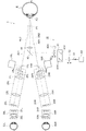
- FIG. 1 shows an optical system for observing the posterior eye part
- FIG. 2 shows an optical system for observing the anterior eye part.
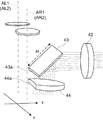
- 3 and 4 are explanatory diagrams of the deflection mirror and the OCT objective lens according to the embodiment.
- FIG. 5 shows an optical system for providing the above-mentioned “function as another ophthalmologic apparatus”.
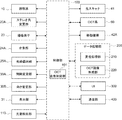
- FIG. 6 shows the configuration of the processing system.
- the ophthalmic microscope system 1 includes an illumination system 10 (10L, 10R), a light receiving system 20 (20L, 20R), an eyepiece system 30 (30L, 30R), an irradiation system 40, and an OCT system 60.
- an illumination system 10 (10L, 10R)
- a light receiving system 20 (20L, 20R)
- an eyepiece system 30 (30L, 30R)
- an irradiation system 40 and an OCT system 60.
- the front lens 90 is disposed immediately before the eye E to be examined.
- a contact lens or the like can be used instead of the non-contact front lens 90 as shown in FIG.
- a contact mirror three-sided mirror or the like
- the illumination system 10 irradiates the eye E with illumination light.
- the illumination system 10 includes a light source that emits illumination light, a diaphragm that defines an illumination field, a lens system, and the like.
- the configuration of the illumination system may be the same as that of a conventional ophthalmologic apparatus (for example, a slit lamp microscope, a fundus camera, a refractometer, etc.).
- the illumination systems 10L and 10R of the present embodiment are configured coaxially with the light receiving systems 20L and 20R, respectively.
- the left light receiving system 20L for acquiring an image presented to the left eye E 0 L of the observer is obliquely provided with a beam splitter 11L made of, for example, a half mirror.
- the beam splitter 11L coaxially couples the optical path of the left illumination system 10L to the optical path of the left light receiving system 20L.
- the illumination light output from the left illumination system 10L is reflected by the beam splitter 11L and illuminates the eye E to be examined coaxially with the left light receiving system 20L.
- the right light receiving system 20R for acquiring an image presented to the right eye E 0 R of the observer is obliquely provided with a beam splitter 11R that couples the optical path of the right illumination system 10R to the optical path of the right light receiving system 20R.
- the beam splitter 11R coaxially couples the optical path of the right illumination system 10R to the optical path of the right light receiving system 20R.
- the illumination light output from the right illumination system 10R is reflected by the beam splitter 11R and illuminates the eye E to be examined coaxially with the right light reception system 20R.
- the position of the illumination light with respect to the optical axis of the light receiving system 20L (20R) can be changed.
- This configuration is realized, for example, by providing means for changing the irradiation position of the illumination light with respect to the beam splitter 11L (11R) as in the conventional microscope for ophthalmic surgery.
- the beam splitter 11L (11R) is arranged between the objective lens 21L (21R) and the eye E, but the position where the optical path of the illumination light is coupled to the light receiving system 20L (20R) is received. Any position in the system 20L (20R) may be used.
- the left light receiving system 20 has a configuration for acquiring an image presented to the left eye E 0 L of the observer, and the right light receiving system 20R is used to acquire an image presented to the right eye E 0 R. It has a configuration.
- the left light receiving system 20L and the right light receiving system 20R have the same configuration.
- the left light receiving system 20L (right light receiving system 20R) includes an objective lens 21L (21R), an imaging lens 22L (22R), and an image sensor 23L (23R).
- an afocal optical path (parallel optical path) is formed between the objective lens 21L (21R) and the imaging lens 22L (22R). It can. As a result, it becomes easy to arrange optical elements such as filters, and to arrange optical path coupling members to couple optical paths from other optical systems (that is, the degree of freedom and expandability of the optical configuration is improved).
- Symbol AL1 indicates the optical axis (objective optical axis) of the objective lens 21L of the left light receiving system 20L
- symbol AR1 indicates the optical axis (objective optical axis) of the objective lens 21R of the right light receiving system 20R.
- the image sensor 23L (23R) is an area sensor such as a CCD image sensor or a CMOS image sensor.
- the above is the configuration of the light receiving system 20 when observing the posterior segment (fundus) of the eye E (FIG. 1).
- the focus lens 24L (24R) and the wedge prism 25L (25R) are arranged at the position on the eye E side with respect to the objective lens 21L (21R). Is done.
- the focus lens 24L (24R) of this example is a concave lens, and acts to extend the focal length of the objective lens 21L (21R).
- the wedge prism 25L (25R) deflects the optical path (objective optical axis AL1 (AR1)) of the left light receiving system 20L (right light receiving system 20R) outward by a predetermined angle (indicated by symbols AL2 and AR2).
- AL1 object optical axis
- AR2 predetermined angle
- the focus lens 24L and the wedge prism 25L are arranged in the left light receiving system 20L
- the focus lens 24R and the wedge prism 25R are arranged in the right light receiving system 20R. Accordingly, the focus position F1 for observing the posterior eye part is switched to the focus position F2 for observing the anterior eye part.
- a convex lens can be used as the focus lens.
- the focus lens is disposed in the optical path when observing the posterior eye part, and is retracted from the optical path when observing the anterior eye part.
- the focal length can be changed continuously or stepwise.
- the wedge prism 25L has a base direction outside (that is, a base-out arrangement), but a base-in arrangement wedge prism can be used.
- the wedge prism is disposed in the optical path when observing the posterior eye part, and is retracted from the optical path when observing the anterior eye part.
- a pair of left and right eyepiece systems 30L and 30R are provided.
- Acquiring left eyepiece system 30L has a configuration to present an image of the eye E obtained by the left light receiving system 20L on the viewer's left eye E 0 L
- right ocular system 30R is the right light receiving system 20R It has a configuration for presenting the image of the eye E to be examined to the right eye E 0 R.
- the left eyepiece system 30L and the right eyepiece system 30R have the same configuration.
- the left eyepiece system 30L (right eyepiece system 30R) includes a display unit 31L (31R) and an eyepiece lens system 32L (32R).
- Display unit 31L (31R) is, for example, a flat panel display such as an LCD.
- the size of the display surface of the display unit 31L (31R) is, for example, (diagonal length) 7 inches or less.
- the screen size of the display device provided in the pair of left and right eyepiece systems 30L and 30R depends on the eye width of the observer (distance between pupils, etc.), the size of the apparatus, the design of the apparatus (arrangement of optical system and mechanism, etc.) Limited. That is, there is a trade-off between such constraints and the apparent field of view. From such a viewpoint, the maximum screen size of the display units 31L and 31R is considered to be about 7 inches.
- the display units 31L and 31R having a screen size exceeding 7 inches can be applied, or the small-sized display units 31L and 31R can be applied. Can be applied.
- the interval between the left eyepiece system 30L and the right eyepiece system 30R can be changed according to the eye width of the observer.
- the relative orientation of the left eyepiece system 30L and the right eyepiece system 30R can be changed. That is, the angle formed by the optical axis of the left eyepiece system 30L and the optical axis of the right eyepiece system 30R can be changed. Thereby, the convergence of both eyes E 0 L and E 0 R can be induced, and stereoscopic viewing by the observer can be supported.
- the irradiation system 40 irradiates the eye E with light for realizing the function as the “other ophthalmologic apparatus” from a direction different from the objective optical axis (AL1 and AR1, and AL2 and AR2) of the light receiving system 20. To do.
- the irradiation system 40 of this example irradiates the eye E with light for OCT (measurement light).
- the irradiation system 40 includes an optical scanner 41, a focus lens 42, a deflection mirror 43, and an OCT objective lens 44.
- Light from the OCT system 60 is guided to the optical scanner 41.
- the focus lens 42 is movable along the optical path of light from the OCT system 60.
- the moving mechanism 42A moves the focus lens 42 along the optical path.
- the moving mechanism 42A is controlled by the control unit 100 described later. For example, the moving mechanism 42A receives the control signal from the control unit 100, and moves the focus lens 42 by the designated movement amount in the movement direction designated by the control signal.
- the light (measurement light) from the OCT system 60 is guided by the optical fiber 51 and emitted from the end face of the fiber.
- a collimating lens 52 is disposed at a position facing the fiber end face.
- the collimating lens 52 converts the measurement light emitted from the fiber end face into a parallel light beam.
- the measurement light converted into a parallel light beam by the collimator lens 52 is guided to the optical scanner 41.
- the collimating lens 52 may be movable along the optical path of the measuring light as a focus lens (or one of the lens groups constituting the focus lens).
- the moving mechanism 42A or a moving mechanism provided separately from the moving mechanism 42A can move the collimator lens 52 along the optical path of the measurement light.
- the moving mechanism for moving the collimating lens 52 is also controlled by the control unit 100 described later. Both the focus lens 42 and the collimating lens 52 may be moved in conjunction or independently by a moving mechanism.
- the optical scanner 41 is a two-dimensional optical scanner, and includes an x scanner 41H that deflects light in the horizontal direction (x direction) and a y scanner 41V that deflects light in the vertical direction (y direction).
- Each of the x scanner 41H and the y scanner 41V may be an arbitrary type of optical scanner, and for example, a galvanometer mirror is used.
- the optical scanner 41 is disposed, for example, at the exit pupil position of the collimating lens 52 or a position in the vicinity thereof. Furthermore, the optical scanner 41 is disposed, for example, at the entrance pupil position of the focus lens 42 or a position in the vicinity thereof.
- a two-dimensional optical scanner is configured by combining two one-dimensional optical scanners as in this example, the two one-dimensional optical scanners are arranged apart by a predetermined distance (for example, about 10 mm). Thereby, for example, any one-dimensional optical scanner can be arranged at the exit pupil position and / or the entrance pupil position.
- the focus lens 42 temporarily forms an image of the parallel light flux (measurement light) that has passed through the optical scanner 41.
- the light that has passed through the focus lens 42 is reflected by the deflection mirror 43 toward the OCT objective lens 44.
- the light passing through the OCT objective lens 44 is irradiated to the eye E.
- the position of the deflection mirror 43 is determined in advance so that the light guided by the irradiation system 40 is irradiated to the eye E from a direction different from the objective optical axis (AL1 and AR1, and AL2 and AR2) of the light receiving system 20. ing.
- the deflection mirror 43 is arranged at a position between the left light receiving system 20L and the right light receiving system 20R where the objective optical axes are arranged non-parallel.
- FIG. 3 schematically shows a perspective view of the deflection mirror 43 and the OCT objective lens 44.
- a cross section of the optical path of the left light receiving system 20L in a direction perpendicular to the objective optical axis AL1 (AL2) and a cross section of the optical path of the right light receiving system 20R in a direction perpendicular to the objective optical axis AR1 (AR2) are schematically illustrated. It is represented.
- a deflecting mirror is provided in the vicinity of the objective optical axes (AL1 and AR1, and AL2 and AR2) of the light receiving system 20.
- 43 and an OCT objective lens 44 are arranged.
- the end 43a on the objective optical axis side of the light receiving system 20 of the deflection mirror 43 and the end 44a on the objective optical axis side of the light receiving system 20 of the OCT objective lens 44 are the optical path of the left light receiving system 20L and the optical path of the right light receiving system 20R. It is close to.
- the optical scanner 41 and the deflecting surface of the deflecting mirror 43 are optically substantially conjugate.
- the deflection surface of the y scanner 41V that deflects the light from the irradiation system 40 in a direction substantially parallel to the objective optical axis of the light receiving system 20 and the deflection surface of the deflection mirror 43 are optically substantially conjugate.
- the deflection surface of the y scanner 41V that deflects the light from the irradiation system 40 in a plane orthogonal to the plane including the pair of objective optical axes of the light receiving system 20 and the deflection surface of the deflection mirror 43 are substantially optical. Arranged in a conjugate. As a result, the size H (see FIG.
- the end 44a on the objective optical axis side of the light receiving system 20 of the OCT objective lens 44 is cut out linearly. Thereby, the observation optical path of the left light receiving system 20L and the observation optical path of the right light receiving system 20R are not blocked by the peripheral edge of the OCT objective lens 44.
- the deflection mirror 43 and the OCT objective lens 44 can be arranged closer to the objective optical axis of the light receiving system 20.
- the end portion 44a is not linear, and may be cut out in a curved shape, for example.
- the deflection mirror 43 is a reflection mirror in which an end 43a on the objective optical axis side of the light receiving system 20 on the deflection surface (reflection surface) is formed in a straight line.
- the end 43a of the deflection mirror 43 and the end 44a of the OCT objective lens 44 are disposed so as to be substantially in contact with the optical path of the left light receiving system 20L and the optical path of the right light receiving system 20R. Thereby, the deflection mirror 43 and the OCT objective lens 44 can be arranged at a position as close as possible to the objective optical axis of the light receiving system 20.
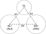
- FIG. 4 schematically shows an optical path arrangement diagram when the optical paths of the light receiving system 20 and the irradiation system 40 are viewed from the objective optical axis direction of the light receiving system 20.
- the objective optical axis AL1 (AL2) of the left light receiving system 20L is provided in the vicinity of the lens center of the left objective lens 21L.
- the objective optical axis AR1 (AR2) of the right light receiving system 20R is provided in the vicinity of the lens center of the right objective lens 21R.
- the objective optical axis OL of the irradiation system 40 is provided in the vicinity of the lens center of the OCT objective lens 44.
- a distance D1 between the lens center of the left objective lens 21L and the lens center of the OCT objective lens 44 and a distance D2 between the lens center of the right objective lens 21R and the lens center of the OCT objective lens 44 are substantially equal. Thereby, light from the irradiation system 40 can be incident from the optical axis direction as close as possible to the objective optical axis of the light receiving system 20.
- the distance D3 (base length) between the lens center of the left objective lens 21L and the lens center of the right objective lens 21R may be longer than the distances D1 and D2 (length of the hypotenuse). Thereby, light from the irradiation system 40 can be incident from the optical axis direction closer to the objective optical axis of the light receiving system 20.
- the deflection mirror 43 and the OCT objective lens 44 can be disposed close to the objective optical axis of the light receiving system 20. Thereby, the light guided by the irradiation system 40 can be incident on the eye E from an incident direction as close to the vertical direction as possible.
- the OCT system 60 includes an interference optical system for performing OCT.
- An example of the configuration of the OCT system 60 is shown in FIG.
- the optical system shown in FIG. 5 is an example of a swept source OCT, which splits light from a wavelength scanning type (wavelength sweep type) light source into measurement light and reference light, and returns return light of measurement light from the eye E to be examined. Interference light is generated by interfering with the reference light passing through the reference light path, and this interference light is detected.
- the detection result (detection signal) of the interference light by the interference optical system is a signal indicating the spectrum of the interference light, and is sent to the control unit 100.
- the light source unit 61 includes a wavelength scanning type (wavelength sweeping type) light source capable of scanning (sweeping) the wavelength of emitted light in the same manner as a general swept source type OCT apparatus.
- the light source unit 61 temporally changes the output wavelength in the near-infrared wavelength band that cannot be visually recognized by the human eye.
- the light L0 output from the light source unit 61 is guided to the polarization controller 63 by the optical fiber 62 and its polarization state is adjusted.
- the light L0 is guided to the fiber coupler 65 by the optical fiber 64 and converted into the measurement light LS and the reference light LR. Divided.
- the reference light LR is guided to a collimator 67 by an optical fiber 66A, converted into a parallel light beam, and guided to a corner cube 70 via an optical path length correction member 68 and a dispersion compensation member 69.
- the optical path length correction member 68 functions as a delay unit for matching the optical path length (optical distance) of the reference light LR with the optical path length of the measurement light LS.
- the dispersion compensation member 69 acts as a dispersion compensation means for matching the dispersion characteristics between the reference light LR and the measurement light LS.
- the corner cube 70 folds the traveling direction of the reference light LR in the reverse direction.
- the corner cube 70 is movable in a direction along the incident optical path and the outgoing optical path of the reference light LR, thereby changing the length of the optical path of the reference light LR.
- any one of a means for changing the length of the optical path of the measurement light LS and a means for changing the length of the optical path of the reference light LR may be provided.
- the reference light LR that has passed through the corner cube 70 passes through the dispersion compensation member 69 and the optical path length correction member 68, is converted from a parallel light beam into a focused light beam by the collimator 71, enters the optical fiber 72, and is guided to the polarization controller 73. Accordingly, the polarization state of the reference light LR is adjusted. Further, the reference light LR is guided to the attenuator 75 by the optical fiber 74, and the light amount is adjusted under the control of the control unit 100. The reference light LR whose light amount has been adjusted is guided to the fiber coupler 77 by the optical fiber 76.
- the measurement light LS generated by the fiber coupler 65 is guided by the optical fiber 51 and emitted from the end face of the fiber, and is converted into a parallel light beam by the collimator lens 52.
- the measurement light LS converted into a parallel light beam is irradiated onto the eye E through the optical scanner 41, the focus lens 42, the deflection mirror 43, and the OCT objective lens 44.
- the measurement light LS is reflected and scattered at various depth positions of the eye E.
- the return light of the measurement light LS from the eye E includes reflected light and backscattered light, travels in the same direction as the forward path in the reverse direction, is guided to the fiber coupler 65, and passes through the optical fiber 66B to the fiber coupler 77. To reach.
- the fiber coupler 77 combines the measurement light LS incident through the optical fiber 66B and the reference light LR incident through the optical fiber 76 to generate interference light.
- the fiber coupler 77 generates a pair of interference light LC by dividing the interference light at a predetermined branching ratio (for example, 1: 1).
- the pair of interference lights LC emitted from the fiber coupler 77 are guided to the detector 79 by optical fibers 78A and 78B, respectively.
- the detector 79 is, for example, a balanced photodiode (Balanced Photo Diode) that includes a pair of photodetectors that respectively detect a pair of interference light LC and outputs a difference between detection results obtained by these.
- the detector 79 sends the detection result (detection signal) to the control unit 100.
- the swept source OCT is applied, but other types of OCT, such as a spectral domain OCT, can be applied.
- Control unit 100 The control part 100 performs control of each part of the ophthalmic microscope system 1 (see FIG. 6). Examples of control of the illumination system 10 include the following: turning on / off the light source, adjusting the amount of light; adjusting the diaphragm; adjusting the slit width when slit illumination is possible. Control of the image sensor 23 includes exposure adjustment, gain adjustment, and shooting rate adjustment.
- the control unit 100 displays various information on the display unit 31.
- the control unit 100 causes the display unit 31L to display an image acquired by the image sensor 23L (or an image obtained by processing the image) and displays an image acquired by the image sensor 23R (or processes it). The image obtained in this manner is displayed on the display unit 31R.
- the measurement light LS is sequentially deflected so that the measurement light LS is irradiated to a plurality of positions according to a preset OCT scan pattern.
- Control targets included in the OCT system 60 include a light source unit 61, a polarization controller 63, a corner cube 70, a polarization controller 73, an attenuator 75, a detector 79, and the like.
- the focus lens 42 (or the collimating lens 52) is moved along the optical path of the measurement light LS.
- control unit 100 controls various mechanisms.
- a stereo angle changing unit 20A a focusing unit 24A, an optical path deflecting unit 25A, an interval changing unit 30A, and an orientation changing unit 30B are provided.
- the stereo angle changing unit 20A relatively rotates and moves the left light receiving system 20L and the right light receiving system 20R. That is, the stereo angle changing unit 20A relatively moves the left light receiving system 20L and the right light receiving system 20R so as to change the angle formed by the objective optical axes (for example, AL1 and AR1).
- This relative movement is, for example, to move the left light receiving system 20L and the right light receiving system 20R by the same angle in opposite rotational directions.
- the direction of the angle bisector formed by the objective optical axes (for example, AL1 and AR1) is constant.
- FIG. 7 shows an example where the stereo angle is enlarged from the state shown in FIG.
- the stereo angle may be defined as an angle formed by the objective optical axis AL1 of the left light receiving system 20L and the objective optical axis AR1 of the right light receiving system 20R, or the objective optical axis AL2 of the left light receiving system 20L and the right light receiving system. It may be defined as an angle formed by the 20R objective optical axis AR2. Even if the stereo angle is changed by the stereo angle changing unit 20A, the relative positions (intervals and relative orientations) of the left and right eyepiece systems 30L and 30R do not change.
- the focal position is adjusted by adjusting the distance between the left and right light receiving systems 20L and 20R with respect to the eye E or changing the focal length of the left and right light receiving systems 20L and 20R in response to the change in the stereo angle. Control can be performed so as not to move.
- the focusing unit 24A inserts / withdraws the left and right focus lenses 24L and 24R from the optical path.
- the focusing unit 24A may be configured to simultaneously insert / retract the left and right focus lenses 24L and 24R.
- the focusing unit 24A may be configured to change the focal position by moving the left and right focus lenses 24L and 24R (simultaneously) in the optical axis direction.
- the focusing unit 24A may be configured to change the focal length by changing (simultaneously) the refractive powers of the left and right focus lenses 24L and 24R.
- the optical path deflecting unit 25A inserts / withdraws the left and right wedge prisms 25L and 25R with respect to the optical path.
- the optical path deflecting unit 25A may be configured to simultaneously insert / retract the left and right wedge prisms 25L and 25R.
- the optical path deflecting unit 25A changes the direction of the optical paths of the left and right light receiving systems 20L and 20R by changing the prism amounts (and prism directions) of the left and right wedge prisms 25L and 25R (simultaneously). May be configured.
- the interval changing unit 30A changes the interval between the left and right eyepiece systems 30L and 30R.
- the interval changing unit 30A may be configured to relatively move the left and right eyepiece systems 30L and 30R without changing the relative directions of the optical axes of each other.
- the orientation changing unit 30B changes the relative orientation of the left and right eyepiece systems 30L and 30R.
- the direction changing unit 30B relatively moves the left eyepiece system 30L and the right eyepiece system 30R so as to change the angle formed by the optical axes of each other.
- This relative movement is, for example, to move the left eyepiece system 30L and the right eyepiece system 30R by the same angle in opposite rotation directions.
- the direction of the bisector of the angle formed by the optical axes of each other is constant.
- the light amount detection unit 110 detects the amount of return light of the measurement light LS irradiated to the eye E. By detecting a part of the return light of the measurement light LS by the light quantity detection unit 110, the light quantity of the return light can be specified.
- an optical path separation member is disposed in the optical path of the return light of the measurement light LS in the irradiation system 40 or the OCT system 60.
- the optical path separating member separates the monitoring optical path from the optical path of the return light.
- the light quantity detection unit 110 is disposed on the monitoring optical path separated by the optical path separation member.
- Such a light quantity detection unit 110 includes, for example, a fiber coupler and a detector, similarly to the configuration shown in FIG. A detection signal from the light amount detection unit 110 is sent to the control unit 100.
- the control unit 100 includes an OCT focusing control unit 101.
- the OCT focus control unit 101 controls the moving mechanism 42 ⁇ / b> A based on the amount of return light of the measurement light LS detected by the light amount detection unit 110.
- the OCT focusing control unit 101 moves the focus lens 42 by controlling the moving mechanism 42A so that the return light of the measurement light LS detected by the light amount detection unit 110 is maximized.
- the OCT focusing control unit 101 can repeatedly execute the above control on the moving mechanism 42A after a predetermined time. Thereby, the focused OCT image can be acquired as a live image.
- the OCT focusing control unit 101 can control the moving mechanism 42A when the light amount of the return light of the measurement light LS detected by the light amount detection unit 110 becomes equal to or less than the first threshold value.
- the first threshold value is set in advance according to the maximum value of the return light amount of the measurement light LS detected by the light amount detection unit 110.
- the first threshold value may be a value obtained by multiplying the maximum value by a predetermined coefficient, or a value obtained by subtracting a predetermined amount of light from the maximum value.
- the OCT focusing control unit 101 may control the moving mechanism 42A based on the intensity of the interference light LC detected by the OCT system 60.
- the OCT focusing control unit 101 controls the moving mechanism 42A based on the detection signal obtained by the detector 79 of the OCT system 60 so that the intensity of the detected interference light LC is maximized.
- the lens 42 is moved.
- the OCT focusing control unit 101 can repeatedly execute the above control on the moving mechanism 42A after a predetermined time. Thereby, the focused OCT image can be acquired as a live image.
- the OCT focusing control unit 101 may execute the above-described control based on the intensity of the interference light LC while performing the above-described control based on the return light of the measurement light LS with respect to the moving mechanism 42A.
- the OCT focusing control unit 101 can execute control of the moving mechanism 42A when the intensity of the interference light LC becomes equal to or lower than the second threshold value.
- the second threshold is set in advance according to the maximum value of the intensity of the interference light LC based on the detection result obtained by the detector 79, for example.
- the second threshold value may be a value obtained by multiplying the maximum value by a predetermined coefficient, or a value obtained by subtracting a predetermined intensity from the maximum value.
- the focus control unit 101 detects a change in the luminance distribution of the image by analyzing the image acquired by at least one of the imaging elements 23L and 23R, and based on the detection result of the change, the movement mechanism 42A. Control may be performed.
- the luminance distribution includes a luminance histogram.
- the focus control unit 101 may execute control of the moving mechanism 42A based on a change in the statistical value of the luminance distribution obtained by analyzing the image.
- the statistical value includes a minimum value, a maximum value, an average value, a median value, a mode value, and the like.
- the focus control unit 101 may detect a change in the luminance distribution in a predetermined region of interest (region of interest) in the acquired image. Thereby, when it is determined that the image acquired by at least one of the imaging elements 23L and 23R has changed, the focus position of the measurement light LS can be changed, and an optimal OCT image can be automatically acquired.
- the data processing unit 200 executes various types of data processing. This data processing includes processing for forming an image, processing for processing an image, and the like. In addition, the data processing unit 200 may be capable of executing processing relating to analysis of images, examination results, and measurement results, and information relating to the subject (such as electronic medical record information).
- the data processing unit 200 includes a scaling processing unit 210 and an OCT image forming unit 220.
- the scaling processing unit 210 enlarges the image acquired by the image sensor 23.
- This process is a so-called digital zoom process, and includes a process of cutting out a part of an image acquired by the image sensor 23 and a process of creating an enlarged image of the part.
- the image clipping range is set by the observer or by the control unit 100.
- the scaling processing unit 210 performs the same processing on the image (left image) acquired by the imaging device 23L of the left light receiving system 20L and the image (right image) acquired by the imaging device 23R of the right light receiving system 20R. Apply. Thereby, images of the same magnification are presented to the left eye E 0 L and the right eye E 0 R of the observer.
- the optical zoom function is realized by providing a variable magnification lens (variable lens system) in each of the left and right light receiving systems 20L and 20R.
- a variable magnification lens variable lens system
- Control related to the optical zoom function is executed by the control unit 100.
- the OCT image forming unit 220 forms an image of the eye E based on the detection result of the interference light LC obtained by the detector 79 of the OCT system 60.
- the control unit 100 sends detection signals sequentially output from the detector 79 to the OCT image forming unit 220.
- the OCT image forming unit 220 performs, for example, Fourier transform or the like on the spectrum distribution based on the detection result obtained by the detector 79 for each series of wavelength scans (for each A line), thereby reflecting the reflection intensity profile in each A line. Form.
- the OCT image forming unit 220 forms image data by imaging each A-line profile. Thereby, a B-scan image (cross-sectional image) and volume data (three-dimensional image data) are obtained.
- the data processing unit 200 may have a function of analyzing the image (OCT image) formed by the OCT image forming unit 220.
- This analysis function includes retinal thickness analysis and comparative analysis with normal eyes. Such an analysis function is executed using a known application.
- the data processing unit 200 may have a function of analyzing an image acquired by the light receiving system 20.
- the data processing unit 200 may include an analysis function that combines analysis of an image acquired by the light receiving system 20 and analysis of an OCT image.
- the user interface (UI) 300 has a function for exchanging information between an observer or the like and the ophthalmic microscope system 1.
- the user interface 300 includes a display device and an operation device (input device).
- the display device may include the display unit 31 and may include other display devices.
- the operation device includes various hardware keys and / or software keys. It is possible to integrally configure at least a part of the operation device and at least a part of the display device.
- a touch panel display is an example.
- the communication unit 400 performs a process for transmitting information to another apparatus and a process for receiving information transmitted from the other apparatus.
- the communication unit 400 may include a communication device that conforms to a predetermined network (LAN, Internet, etc.). For example, the communication unit 400 acquires information from an electronic medical record database or a medical image database via a LAN provided in a medical institution.
- the communication unit 400 converts an image acquired by the ophthalmic microscope system 1 (an image acquired by the light receiving system 20, an OCT image, etc.) to the external monitor substantially in real time. Can be sent.
- the ophthalmic microscope system includes an illumination system (illumination systems 10, 10L, 10R), a pair of light receiving systems (light receiving systems 20, 20L, 20R), and an interference optical system (irradiation system 40 and OCT system 60). And a moving mechanism (moving mechanism 42A), a control unit (control unit 100), and a data processing unit (data processing unit 200).
- the illumination system irradiates the eye to be examined (eye E to be examined) with illumination light.
- the pair of light receiving systems includes an objective lens (objective lenses 21L and 21R) and an imaging device (imaging devices 23L and 23R), respectively.
- the pair of light receiving systems have their respective objective optical axes (objective optical axes AL1 (AL2) and AR1 (AR2)) arranged non-parallel, and return light of the illumination light irradiated to the eye to be examined is passed through each objective lens.
- the interference optical system includes a focus lens (focus lens 42 and collimator lens 52) and an OCT objective lens (OCT objective lens 44).
- the interference optical system divides the light from the OCT light source (light source unit 61) into measurement light (measurement light LS) and reference light (reference light LR), which is different from the objective optical axis via the focus lens and the OCT objective lens.
- Interference light (interference light LC) between the return light of the measurement light irradiated on the eye to be examined from the direction and the reference light is detected.
- the moving mechanism moves the focus lens.
- the control unit controls the moving mechanism.
- the data processing unit generates an image of the eye to be examined or an analysis result based on the detection result of the interference light.
- an ophthalmic microscope system capable of acquiring an OCT image while observing the eye to be examined without limiting the degree of freedom in optical design and mechanism design. Further, since the eye to be examined is irradiated with the measurement light via the focus lens that is moved by the moving mechanism that can be controlled by the control unit, the focused OCT image can be acquired in real time. Therefore, even when the shape of the cornea or the like is instantaneously deformed during the operation, it is not necessary to manually adjust the focus of the OCT image, and the operation is continued while always observing the focused OCT image. It becomes possible.
- the ophthalmic microscope system includes a light amount detection unit (light amount detection unit 110) that detects the amount of return light of the measurement light, and the control unit is configured to move the movement mechanism based on the detection result of the light amount detection unit. Control may be performed.
- a light amount detection unit light amount detection unit 110
- the control unit is configured to move the movement mechanism based on the detection result of the light amount detection unit. Control may be performed.
- the focus lens is moved based on the amount of return light of the measurement light irradiated to the eye to be examined, focusing control based on the amount of light becomes possible, and thereby focusing is performed.
- the obtained OCT image can be easily acquired.
- control unit may execute the control of the moving mechanism when the amount of the return light becomes equal to or less than the first threshold value.
- control unit may execute control of the moving mechanism based on the intensity of the interference light detected by the interference optical system.
- the focus lens is moved based on the intensity of the interference light based on the return light of the measurement light and the reference light irradiated on the eye to be examined, focusing based on the intensity of the interference light is performed. Control becomes possible. Thereby, the focused OCT image can be easily acquired.
- control unit may execute the control of the moving mechanism when the intensity of the interference light becomes equal to or less than the second threshold value.
- control unit detects a change in the luminance distribution of the image by analyzing the image acquired by the image sensor, and controls the moving mechanism based on the detection result of the change. May be executed.
- the ophthalmic microscope system includes an optical scanner (optical scanner 41) for scanning the eye to be examined with measurement light, and the focus lens is disposed between the optical scanner and the OCT objective lens. Also good.
- a focused OCT image can be automatically acquired by the movement of the focus lens arranged between the optical scanner and the OCT objective lens.
- the interference optical system includes an optical fiber (optical fiber 51) that guides measurement light, and the focus lens emits the measurement light emitted from the optical fiber and directed toward the eye to be examined.
- a collimating lens may be included.
- the focused OCT image can be automatically acquired by the movement of the collimating lens arranged at the position facing the emission end of the optical fiber that guides the measurement light to the eye to be examined.
- the focus lenses 24L and 24R and the wedge prisms 25L and 25R are retracted from the optical path during fundus observation, and are inserted into the optical path during anterior segment observation.
- Such an operation can be automated.
- an auxiliary optical member for changing the observation site of the eye to be examined is used.
- the front lens 90 is disposed in the optical path during fundus observation and is retracted from the optical path during anterior eye observation.
- the ophthalmic microscope system of this modification changes the states of the focus lenses 24L and 24R according to the state of the auxiliary optical member (that is, the selection of the observation site). That is, the control unit 100 controls the second mechanism for linking the focus lenses 24L and 24R according to the change of the observation site by the auxiliary optical member. Similarly, the control unit 100 controls the third mechanism for operating the wedge prisms 25L and 25R in association with changes in the observation site by the auxiliary optical member.
- the control unit 100 controls the focusing unit 24A and the optical path deflecting unit 25A so that the focus lenses 24L and 24R and the wedge prisms 25L and 25R are inserted into the optical path. .
- the control unit 100 controls the focusing unit 24A and the optical path deflecting unit 25A so as to retract from the focus lenses 24L and 24R and the wedge prisms 25L and 25R in response to the insertion of the front lens 90 in the optical path. To do.
- the ophthalmic microscope system may include a configuration for generating information indicating the state of the auxiliary optical member (for example, whether or not the front lens 90 is inserted in the optical path).
- the arrangement state of the arm that holds the front lens 90 can be detected using a sensor such as a microswitch.
- the current state of the front lens 90 can be recognized by referring to the control history.
- the data processing unit 200 analyzes an image acquired in a state where the focus lens 24L and the like are arranged on the optical path, thereby obtaining an amount indicating the blurred state of the image.
- the amount of blur is equal to or greater than the threshold value, it is determined that the front lens 90 is disposed in the optical path.
- the amount of blur is less than the threshold value, it is determined that the front lens 90 is retracted from the optical path.
- the state of the front lens 90 can be determined in the same manner.
- the state of the lens for changing the focal position (focus lenses 24L and 24R) and the state of the deflection member (wedge prisms 25L and 25R) for deflecting the optical path are used for switching the observation site. It can be changed automatically. Therefore, the operability can be further improved.
- the illumination systems (10L and 10R) of the above embodiment are arranged coaxially with the pair of light receiving systems (20L and 20R).
- a configuration in which an illumination system is arranged non-coaxially with respect to a pair of light receiving systems that is, a configuration in which illumination light can be irradiated from a direction different from the objective optical axis of the pair of light receiving systems will be described.
- a configuration example of the optical system of this modification is shown in FIG.
- the illumination system 10S of the ophthalmic microscope system 1A can irradiate, for example, slit light to the eye to be examined.
- a typical example of such an ophthalmic microscope is a slit lamp microscope.
- the relative positions of the illumination system 10S and the light receiving systems 20L and 20R can be changed like a slit lamp microscope. That is, the illumination system 10S and the light receiving systems 20L and 20R are configured to be rotatable around the same axis. Thereby, it is possible to observe the cross section of the cornea etc. illuminated with the slit light from an oblique direction.
- the ophthalmic microscope system may include one or both of the coaxial illumination system as in the above embodiment and the non-coaxial illumination system as in this modification.
- the illumination system to be used can be switched in accordance with, for example, switching of the observation site.
Landscapes
- Health & Medical Sciences (AREA)
- Life Sciences & Earth Sciences (AREA)
- Ophthalmology & Optometry (AREA)
- Surgery (AREA)
- Engineering & Computer Science (AREA)
- Animal Behavior & Ethology (AREA)
- Biomedical Technology (AREA)
- Heart & Thoracic Surgery (AREA)
- Veterinary Medicine (AREA)
- Public Health (AREA)
- General Health & Medical Sciences (AREA)
- Molecular Biology (AREA)
- Physics & Mathematics (AREA)
- Medical Informatics (AREA)
- Nuclear Medicine, Radiotherapy & Molecular Imaging (AREA)
- Biophysics (AREA)
- Vascular Medicine (AREA)
- Optics & Photonics (AREA)
- Oral & Maxillofacial Surgery (AREA)
- Pathology (AREA)
- Eye Examination Apparatus (AREA)
Abstract
La présente invention acquiert automatiquement une image OCT concentrée, tandis qu'un œil en cours d'examen est observé. Le système de microscope ophtalmologique selon les modes de réalisation comprend un système d'éclairage, une paire de systèmes de réception de lumière, un système optique d'interférence, un mécanisme de mouvement, une unité de commande et une unité de traitement de données. Le système d'éclairage émet la lumière d'éclairage au niveau d'un œil en cours d'examen. La paire de systèmes de réception de lumière comprennent des objectifs et des éléments d'imagerie respectifs, sont agencés de telle sorte que les axes optiques d'objectif de des derniers ne sont pas parallèles l'un par rapport à l'autre, et, par l'intermédiaire des objectifs respectifs de ces derniers, guident la lumière de retour qui provient de la lumière d'éclairage qui a été émise au niveau de l'œil en cours d'examen vers les éléments d'imagerie respectifs de ces derniers. Le système optique d'interférence comprend une lentille de mise au point et un objectif OCT, sépare la lumière qui provient d'une source de lumière OCT en une lumière de mesure et une lumière de référence, et détecte, par l'intermédiaire de la lentille de mise au point et de l'objectif OCT, la lumière d'interférence entre la lumière de référence et la lumière de retour qui provient de la lumière de mesure qui a été émise au niveau de l'œil en cours d'examen depuis une direction qui est différente de l'axe optique d'objectif. Le mécanisme de mouvement déplace la lentille de mise au point. L'unité de commande commande le mécanisme de mouvement. L'unité de traitement de données génère des résultats d'analyse ou une image de l'œil en cours d'examen, sur la base des résultats de détection pour la lumière d'interférence.
Applications Claiming Priority (2)
| Application Number | Priority Date | Filing Date | Title |
|---|---|---|---|
| JP2015132085A JP6499937B2 (ja) | 2015-06-30 | 2015-06-30 | 眼科用顕微鏡システム |
| JP2015-132085 | 2015-06-30 |
Publications (1)
| Publication Number | Publication Date |
|---|---|
| WO2017002379A1 true WO2017002379A1 (fr) | 2017-01-05 |
Family
ID=57608395
Family Applications (1)
| Application Number | Title | Priority Date | Filing Date |
|---|---|---|---|
| PCT/JP2016/053283 Ceased WO2017002379A1 (fr) | 2015-06-30 | 2016-02-03 | Système de microscope ophtalmologique |
Country Status (2)
| Country | Link |
|---|---|
| JP (1) | JP6499937B2 (fr) |
| WO (1) | WO2017002379A1 (fr) |
Cited By (10)
| Publication number | Priority date | Publication date | Assignee | Title |
|---|---|---|---|---|
| JP2018157969A (ja) * | 2017-03-23 | 2018-10-11 | 株式会社トプコン | 眼科装置 |
| US10610096B2 (en) | 2016-12-21 | 2020-04-07 | Acucela Inc. | Miniaturized mobile, low cost optical coherence tomography system for home based ophthalmic applications |
| US11357401B2 (en) | 2018-06-20 | 2022-06-14 | Acucela Inc. | Miniaturized mobile, low cost optical coherence tomography system for home based ophthalmic applications |
| US11393094B2 (en) | 2020-09-11 | 2022-07-19 | Acucela Inc. | Artificial intelligence for evaluation of optical coherence tomography images |
| US11497396B2 (en) | 2021-03-24 | 2022-11-15 | Acucela Inc. | Axial length measurement monitor |
| US11684254B2 (en) | 2020-08-04 | 2023-06-27 | Acucela Inc. | Scan pattern and signal processing for optical coherence tomography |
| US11730363B2 (en) | 2019-12-26 | 2023-08-22 | Acucela Inc. | Optical coherence tomography patient alignment system for home based ophthalmic applications |
| US11911105B2 (en) | 2020-09-30 | 2024-02-27 | Acucela Inc. | Myopia prediction, diagnosis, planning, and monitoring device |
| US11974807B2 (en) | 2020-08-14 | 2024-05-07 | Acucela Inc. | System and method for optical coherence tomography a-scan decurving |
| US12262948B2 (en) | 2017-08-30 | 2025-04-01 | Topcon Corporation | Microscope and function expansion unit |
Families Citing this family (2)
| Publication number | Priority date | Publication date | Assignee | Title |
|---|---|---|---|---|
| JP6839901B2 (ja) * | 2017-05-02 | 2021-03-10 | 株式会社トプコン | 眼科用顕微鏡 |
| CN116490117A (zh) * | 2020-10-27 | 2023-07-25 | 株式会社拓普康 | 眼科观察装置 |
Citations (3)
| Publication number | Priority date | Publication date | Assignee | Title |
|---|---|---|---|---|
| JP2011515194A (ja) * | 2008-03-27 | 2011-05-19 | ドヘニー アイ インスティテュート | 光干渉断層装置、方法、およびシステム |
| JP2012509729A (ja) * | 2008-11-26 | 2012-04-26 | カール ツァイス サージカル ゲーエムベーハー | 画像化システム |
| JP2012213634A (ja) * | 2011-03-31 | 2012-11-08 | Nidek Co Ltd | 眼科用レーザ治療装置 |
-
2015
- 2015-06-30 JP JP2015132085A patent/JP6499937B2/ja active Active
-
2016
- 2016-02-03 WO PCT/JP2016/053283 patent/WO2017002379A1/fr not_active Ceased
Patent Citations (3)
| Publication number | Priority date | Publication date | Assignee | Title |
|---|---|---|---|---|
| JP2011515194A (ja) * | 2008-03-27 | 2011-05-19 | ドヘニー アイ インスティテュート | 光干渉断層装置、方法、およびシステム |
| JP2012509729A (ja) * | 2008-11-26 | 2012-04-26 | カール ツァイス サージカル ゲーエムベーハー | 画像化システム |
| JP2012213634A (ja) * | 2011-03-31 | 2012-11-08 | Nidek Co Ltd | 眼科用レーザ治療装置 |
Cited By (21)
| Publication number | Priority date | Publication date | Assignee | Title |
|---|---|---|---|---|
| US11627874B2 (en) | 2016-12-21 | 2023-04-18 | Acucela Inc. | Miniaturized mobile, low cost optical coherence tomography system for home based ophthalmic applications |
| US10610096B2 (en) | 2016-12-21 | 2020-04-07 | Acucela Inc. | Miniaturized mobile, low cost optical coherence tomography system for home based ophthalmic applications |
| US10952607B2 (en) | 2016-12-21 | 2021-03-23 | Acucela Inc. | Miniaturized mobile, low cost optical coherence tomography system for home based ophthalmic applications |
| US11890053B2 (en) | 2016-12-21 | 2024-02-06 | Acucela Inc. | Miniaturized mobile, low cost optical coherence tomography system for home based ophthalmic applications |
| US12396639B2 (en) | 2016-12-21 | 2025-08-26 | Acucela Inc. | Miniaturized mobile, low cost optical coherence tomography system for home based ophthalmic applications |
| JP2018157969A (ja) * | 2017-03-23 | 2018-10-11 | 株式会社トプコン | 眼科装置 |
| US12262948B2 (en) | 2017-08-30 | 2025-04-01 | Topcon Corporation | Microscope and function expansion unit |
| US11576572B2 (en) | 2018-06-20 | 2023-02-14 | Acucela Inc. | Miniaturized mobile, low cost optical coherence tomography system for home based ophthalmic applications |
| US12290317B2 (en) | 2018-06-20 | 2025-05-06 | Acucela Inc. | Miniaturized mobile, low cost optical coherence tomography system for home based ophthalmic applications |
| US11357401B2 (en) | 2018-06-20 | 2022-06-14 | Acucela Inc. | Miniaturized mobile, low cost optical coherence tomography system for home based ophthalmic applications |
| US11896308B2 (en) | 2018-06-20 | 2024-02-13 | Acucela Inc. | Miniaturized mobile, low cost optical coherence tomography system for home based ophthalmic applications |
| US11730363B2 (en) | 2019-12-26 | 2023-08-22 | Acucela Inc. | Optical coherence tomography patient alignment system for home based ophthalmic applications |
| US12232810B2 (en) | 2020-08-04 | 2025-02-25 | Acucela Inc. | Scan pattern and signal processing for optical coherence tomography |
| US11684254B2 (en) | 2020-08-04 | 2023-06-27 | Acucela Inc. | Scan pattern and signal processing for optical coherence tomography |
| US11974807B2 (en) | 2020-08-14 | 2024-05-07 | Acucela Inc. | System and method for optical coherence tomography a-scan decurving |
| US11393094B2 (en) | 2020-09-11 | 2022-07-19 | Acucela Inc. | Artificial intelligence for evaluation of optical coherence tomography images |
| US11798164B2 (en) | 2020-09-11 | 2023-10-24 | Acucela Inc. | Artificial intelligence for evaluation of optical coherence tomography images |
| US11620749B2 (en) | 2020-09-11 | 2023-04-04 | Acucela Inc. | Artificial intelligence for evaluation of optical coherence tomography images |
| US11911105B2 (en) | 2020-09-30 | 2024-02-27 | Acucela Inc. | Myopia prediction, diagnosis, planning, and monitoring device |
| US11779206B2 (en) | 2021-03-24 | 2023-10-10 | Acucela Inc. | Axial length measurement monitor |
| US11497396B2 (en) | 2021-03-24 | 2022-11-15 | Acucela Inc. | Axial length measurement monitor |
Also Published As
| Publication number | Publication date |
|---|---|
| JP2017012430A (ja) | 2017-01-19 |
| JP6499937B2 (ja) | 2019-04-10 |
Similar Documents
| Publication | Publication Date | Title |
|---|---|---|
| JP6499937B2 (ja) | 眼科用顕微鏡システム | |
| JP6490469B2 (ja) | 眼科用顕微鏡システム | |
| JP6502720B2 (ja) | 眼科用顕微鏡 | |
| US11166631B2 (en) | Ophthalmologic microscope and function expansion unit | |
| JP6499936B2 (ja) | 眼科用顕微鏡システム | |
| JP6490519B2 (ja) | 眼科用顕微鏡システム | |
| US11871994B2 (en) | Ophthalmologic microscope and function expansion unit | |
| JP6505539B2 (ja) | 眼科用顕微鏡 | |
| JP6538466B2 (ja) | 眼科用顕微鏡 | |
| JP2017217290A (ja) | 眼科用手術顕微鏡 | |
| JP6505527B2 (ja) | 眼科用顕微鏡 | |
| JP2017029333A (ja) | 眼科用顕微鏡 | |
| US11503996B2 (en) | Ophthalmic microscope and functionality enhancement unit | |
| US10531984B2 (en) | Ophthalmologic microscope system | |
| JP6588750B2 (ja) | 眼科用顕微鏡システム | |
| WO2017110145A1 (fr) | Système de microscopie ophtalmique | |
| JP6577266B2 (ja) | 眼科用顕微鏡 | |
| JP2017012536A (ja) | 眼科用顕微鏡 | |
| JP2022091766A (ja) | Oct機能拡張ユニット |
Legal Events
| Date | Code | Title | Description |
|---|---|---|---|
| 121 | Ep: the epo has been informed by wipo that ep was designated in this application |
Ref document number: 16817489 Country of ref document: EP Kind code of ref document: A1 |
|
| NENP | Non-entry into the national phase |
Ref country code: DE |
|
| 122 | Ep: pct application non-entry in european phase |
Ref document number: 16817489 Country of ref document: EP Kind code of ref document: A1 |