WO2017002582A1 - Dispositif pour fabriquer un faisceau de fibres coupées et procédé de fabrication de celui-ci - Google Patents
Dispositif pour fabriquer un faisceau de fibres coupées et procédé de fabrication de celui-ci Download PDFInfo
- Publication number
- WO2017002582A1 WO2017002582A1 PCT/JP2016/067328 JP2016067328W WO2017002582A1 WO 2017002582 A1 WO2017002582 A1 WO 2017002582A1 JP 2016067328 W JP2016067328 W JP 2016067328W WO 2017002582 A1 WO2017002582 A1 WO 2017002582A1
- Authority
- WO
- WIPO (PCT)
- Prior art keywords
- roll
- fiber bundle
- cutter
- chopped fiber
- reinforcing fiber
- Prior art date
- Legal status (The legal status is an assumption and is not a legal conclusion. Google has not performed a legal analysis and makes no representation as to the accuracy of the status listed.)
- Ceased
Links
Images




Classifications
-
- B—PERFORMING OPERATIONS; TRANSPORTING
- B26—HAND CUTTING TOOLS; CUTTING; SEVERING
- B26D—CUTTING; DETAILS COMMON TO MACHINES FOR PERFORATING, PUNCHING, CUTTING-OUT, STAMPING-OUT OR SEVERING
- B26D1/00—Cutting through work characterised by the nature or movement of the cutting member or particular materials not otherwise provided for; Apparatus or machines therefor; Cutting members therefor
- B26D1/01—Cutting through work characterised by the nature or movement of the cutting member or particular materials not otherwise provided for; Apparatus or machines therefor; Cutting members therefor involving a cutting member which does not travel with the work
- B26D1/12—Cutting through work characterised by the nature or movement of the cutting member or particular materials not otherwise provided for; Apparatus or machines therefor; Cutting members therefor involving a cutting member which does not travel with the work having a cutting member moving about an axis
- B26D1/14—Cutting through work characterised by the nature or movement of the cutting member or particular materials not otherwise provided for; Apparatus or machines therefor; Cutting members therefor involving a cutting member which does not travel with the work having a cutting member moving about an axis with a circular cutting member, e.g. disc cutter
- B26D1/143—Cutting through work characterised by the nature or movement of the cutting member or particular materials not otherwise provided for; Apparatus or machines therefor; Cutting members therefor involving a cutting member which does not travel with the work having a cutting member moving about an axis with a circular cutting member, e.g. disc cutter rotating about a stationary axis
- B26D1/15—Cutting through work characterised by the nature or movement of the cutting member or particular materials not otherwise provided for; Apparatus or machines therefor; Cutting members therefor involving a cutting member which does not travel with the work having a cutting member moving about an axis with a circular cutting member, e.g. disc cutter rotating about a stationary axis with vertical cutting member
-
- B—PERFORMING OPERATIONS; TRANSPORTING
- B26—HAND CUTTING TOOLS; CUTTING; SEVERING
- B26D—CUTTING; DETAILS COMMON TO MACHINES FOR PERFORATING, PUNCHING, CUTTING-OUT, STAMPING-OUT OR SEVERING
- B26D1/00—Cutting through work characterised by the nature or movement of the cutting member or particular materials not otherwise provided for; Apparatus or machines therefor; Cutting members therefor
- B26D1/01—Cutting through work characterised by the nature or movement of the cutting member or particular materials not otherwise provided for; Apparatus or machines therefor; Cutting members therefor involving a cutting member which does not travel with the work
- B26D1/12—Cutting through work characterised by the nature or movement of the cutting member or particular materials not otherwise provided for; Apparatus or machines therefor; Cutting members therefor involving a cutting member which does not travel with the work having a cutting member moving about an axis
- B26D1/14—Cutting through work characterised by the nature or movement of the cutting member or particular materials not otherwise provided for; Apparatus or machines therefor; Cutting members therefor involving a cutting member which does not travel with the work having a cutting member moving about an axis with a circular cutting member, e.g. disc cutter
- B26D1/143—Cutting through work characterised by the nature or movement of the cutting member or particular materials not otherwise provided for; Apparatus or machines therefor; Cutting members therefor involving a cutting member which does not travel with the work having a cutting member moving about an axis with a circular cutting member, e.g. disc cutter rotating about a stationary axis
- B26D1/153—Cutting through work characterised by the nature or movement of the cutting member or particular materials not otherwise provided for; Apparatus or machines therefor; Cutting members therefor involving a cutting member which does not travel with the work having a cutting member moving about an axis with a circular cutting member, e.g. disc cutter rotating about a stationary axis with inclined cutting member
-
- B—PERFORMING OPERATIONS; TRANSPORTING
- B26—HAND CUTTING TOOLS; CUTTING; SEVERING
- B26D—CUTTING; DETAILS COMMON TO MACHINES FOR PERFORATING, PUNCHING, CUTTING-OUT, STAMPING-OUT OR SEVERING
- B26D1/00—Cutting through work characterised by the nature or movement of the cutting member or particular materials not otherwise provided for; Apparatus or machines therefor; Cutting members therefor
- B26D1/01—Cutting through work characterised by the nature or movement of the cutting member or particular materials not otherwise provided for; Apparatus or machines therefor; Cutting members therefor involving a cutting member which does not travel with the work
- B26D1/12—Cutting through work characterised by the nature or movement of the cutting member or particular materials not otherwise provided for; Apparatus or machines therefor; Cutting members therefor involving a cutting member which does not travel with the work having a cutting member moving about an axis
- B26D1/14—Cutting through work characterised by the nature or movement of the cutting member or particular materials not otherwise provided for; Apparatus or machines therefor; Cutting members therefor involving a cutting member which does not travel with the work having a cutting member moving about an axis with a circular cutting member, e.g. disc cutter
- B26D1/22—Cutting through work characterised by the nature or movement of the cutting member or particular materials not otherwise provided for; Apparatus or machines therefor; Cutting members therefor involving a cutting member which does not travel with the work having a cutting member moving about an axis with a circular cutting member, e.g. disc cutter coacting with a movable member, e.g. a roller
- B26D1/225—Cutting through work characterised by the nature or movement of the cutting member or particular materials not otherwise provided for; Apparatus or machines therefor; Cutting members therefor involving a cutting member which does not travel with the work having a cutting member moving about an axis with a circular cutting member, e.g. disc cutter coacting with a movable member, e.g. a roller for thin material, e.g. for sheets, strips or the like
-
- B—PERFORMING OPERATIONS; TRANSPORTING
- B26—HAND CUTTING TOOLS; CUTTING; SEVERING
- B26D—CUTTING; DETAILS COMMON TO MACHINES FOR PERFORATING, PUNCHING, CUTTING-OUT, STAMPING-OUT OR SEVERING
- B26D5/00—Arrangements for operating and controlling machines or devices for cutting, cutting-out, stamping-out, punching, perforating, or severing by means other than cutting
-
- B—PERFORMING OPERATIONS; TRANSPORTING
- B26—HAND CUTTING TOOLS; CUTTING; SEVERING
- B26D—CUTTING; DETAILS COMMON TO MACHINES FOR PERFORATING, PUNCHING, CUTTING-OUT, STAMPING-OUT OR SEVERING
- B26D7/00—Details of apparatus for cutting, cutting-out, stamping-out, punching, perforating, or severing by means other than cutting
- B26D7/08—Means for treating work or cutting member to facilitate cutting
-
- C—CHEMISTRY; METALLURGY
- C03—GLASS; MINERAL OR SLAG WOOL
- C03B—MANUFACTURE, SHAPING, OR SUPPLEMENTARY PROCESSES
- C03B37/00—Manufacture or treatment of flakes, fibres, or filaments from softened glass, minerals, or slags
- C03B37/10—Non-chemical treatment
- C03B37/16—Cutting or severing
-
- D—TEXTILES; PAPER
- D01—NATURAL OR MAN-MADE THREADS OR FIBRES; SPINNING
- D01G—PRELIMINARY TREATMENT OF FIBRES, e.g. FOR SPINNING
- D01G1/00—Severing continuous filaments or long fibres, e.g. stapling
- D01G1/02—Severing continuous filaments or long fibres, e.g. stapling to form staple fibres not delivered in strand form
- D01G1/04—Severing continuous filaments or long fibres, e.g. stapling to form staple fibres not delivered in strand form by cutting
-
- D—TEXTILES; PAPER
- D01—NATURAL OR MAN-MADE THREADS OR FIBRES; SPINNING
- D01G—PRELIMINARY TREATMENT OF FIBRES, e.g. FOR SPINNING
- D01G1/00—Severing continuous filaments or long fibres, e.g. stapling
- D01G1/06—Converting tows to slivers or yarns, e.g. in direct spinning
- D01G1/10—Converting tows to slivers or yarns, e.g. in direct spinning by cutting
-
- D—TEXTILES; PAPER
- D06—TREATMENT OF TEXTILES OR THE LIKE; LAUNDERING; FLEXIBLE MATERIALS NOT OTHERWISE PROVIDED FOR
- D06H—MARKING, INSPECTING, SEAMING OR SEVERING TEXTILE MATERIALS
- D06H7/00—Apparatus or processes for cutting, or otherwise severing, specially adapted for the cutting, or otherwise severing, of textile materials
- D06H7/10—Apparatus or processes for cutting, or otherwise severing, specially adapted for the cutting, or otherwise severing, of textile materials obliquely
-
- B—PERFORMING OPERATIONS; TRANSPORTING
- B26—HAND CUTTING TOOLS; CUTTING; SEVERING
- B26D—CUTTING; DETAILS COMMON TO MACHINES FOR PERFORATING, PUNCHING, CUTTING-OUT, STAMPING-OUT OR SEVERING
- B26D1/00—Cutting through work characterised by the nature or movement of the cutting member or particular materials not otherwise provided for; Apparatus or machines therefor; Cutting members therefor
- B26D1/0006—Cutting members therefor
- B26D2001/0033—Cutting members therefor assembled from multiple blades
Definitions
- the present invention when used as a molding material, has a good impregnation property, fluidity and molding followability, and when used as a fiber reinforced plastic, an apparatus for manufacturing a chopped fiber bundle that exhibits excellent mechanical properties and a manufacturing method thereof It is about.
- Fiber reinforced plastic consisting of reinforced fiber and matrix resin is attracting attention in industrial applications because it has high specific properties, high specific modulus, excellent mechanical properties, weather resistance, chemical resistance, etc.
- the demand is increasing year by year.
- a molding method suitable for a complicated shape such as a three-dimensional shape
- a bundle of discontinuous reinforcing fibers for example, carbon fibers
- a matrix resin for example, a resin for polyurethane resin
- a technique for producing a molded product having a desired shape by using a molding material by heating and pressure molding is known, and molding using a SMC (sheet molding compound) or a stampable sheet is mainly mentioned. .
- An SMC molded product is a sheet in which a fiber bundle of reinforcing fibers is cut in a direction perpendicular to the fiber so that the fiber length is, for example, about 25 mm, and the chopped fiber bundle is impregnated with a matrix resin that is a thermosetting resin to be in a semi-cured state It is obtained by heating and pressurizing the shaped substrate (SMC) using a heating type press.
- a stampable sheet molded product is obtained by thermoplasticizing a sheet-like base material (stampable sheet) in which a thermoplastic resin is impregnated with a chopped fiber bundle cut to about 25 mm or a nonwoven mat made of continuous reinforcing fibers with an infrared heater.
- the SMC or stampable sheet is cut smaller than the shape of the molded body before being pressed, placed on the mold, and stretched (flowed) into the shape of the molded body by pressing. Since these fibers are discontinuous, the reinforcing fiber bundle can flow freely together with the resin, so that it is possible to follow a complicated shape such as a three-dimensional shape.
- Patent Document 1 there is no specific method in Patent Document 1 for actually cutting the reinforcing fiber obliquely.
- Patent Document 2 mentions a cutting roll in which cutting blades are arranged obliquely on a rotating roll.
- the manufacturing cost is high due to the complicated shape, and only the blade portion is replaced like a normal cutter roll. Therefore, the cost of blade replacement becomes very large, and it is unrealistic to apply to actual production.
- high-strength fibers such as carbon fibers and aramid fibers
- the strength of the fibers themselves is high, so the blade wears out quickly, and this problem is remarkable.
- patent document 3 the method of inclining and introducing a fiber into a cutter roll having a shape in which straight blades are arranged in the circumferential direction of the roll, as in a normal cutter roll, is mentioned. Is possible, so the above problem is avoided. However, in this method, in order to cut continuously while maintaining the fiber direction of the yarn in an oblique direction, the shape and fiber direction of the yarn must not change due to the pulling of the roll. Processing such as fixing to the top was necessary. In Patent Document 3, a method of hardening fibers by resin impregnation is mentioned, but it is not a preferable method because it leads to an improvement in cost.
- the yarn path needs to be inclined by 85 ° and introduced into the cutter roll, which means that the fiber direction is introduced substantially parallel to the rotation axis of the cutter. Therefore, it has been very difficult to continuously introduce the introduction angle constant while maintaining the fiber shape at such an angle.
- the object of the present invention is to produce a chopped fiber bundle that allows continuous oblique cutting of reinforcing fiber yarns with a simple device and enables oblique cutting at a smaller angle with a simple apparatus.
- An apparatus and a method for manufacturing the same are provided.
- a cutter roll in which one or a plurality of disk blades are attached to the outer periphery of the roll body so that the rotation axis of the roll body coincides with the central axis, and is arranged in parallel with the rotation axis direction of the roll body.
- a chopped fiber bundle manufacturing apparatus that continuously feeds a reinforcing fiber yarn between the nip roll and the cutter roll and continuously cuts the cutter roll. And at least one of a reciprocating drive mechanism for reciprocating the cutter roll in the direction of the rotation axis of the roll body, or a traverse guide for traversing the reinforcing fiber yarn in the direction of the rotation axis of the roll body.
- the chopped fiber bundle manufacturing apparatus according to any one of (1) to (5), wherein the cutter roll is one in which disk blades and spacers are alternately arranged on the outer periphery of the roll body.
- the reinforcing fiber yarn is made of carbon fiber.
- a chopped fiber bundle that continuously feeds a reinforcing fiber yarn between the cutter roll and the nip roll while continuously rotating the cutter roll.
- the reinforcing fiber yarn is continuously A method for producing a chopped fiber bundle, characterized by cutting.
- a chopped fiber bundle manufacturing apparatus and method for manufacturing a chopped fiber bundle that can continuously and obliquely cut reinforcing fiber yarns with a simple apparatus, and further enables oblique cutting at a smaller angle. Can do.
- FIG. 2 shows the cutting length of a chopped fiber bundle.
- FIG. 2 shows the cutting length of a chopped fiber bundle.
- FIG. 2 shows the cutting length of a chopped fiber bundle.
- FIG. 2 shows the cutting length of a chopped fiber bundle.
- FIG. 2 shows the cutting length of a chopped fiber bundle.
- FIG. 2 shows the cutting length of a chopped fiber bundle.
- the schematic shows an example of the disk blade arrange
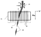
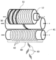
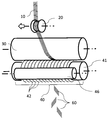
- the manufacturing apparatus used in the present invention includes a cutter roll 40 in which one or a plurality of disk blades 42 are attached to the outer periphery of the roll body 41 so that the rotation axis and the center axis of the roll body 41 coincide with each other, and the roll body 41. And a nip roll 30 disposed in parallel with the rotational axis direction of the nip roll 30. Further, in order to feed the reinforcing fiber yarn 10 between the nip roll 30 and the cutter roll 40 and continuously cut it, a rotation drive mechanism (not shown) for rotating the cutter roll 40 is provided.
- a reciprocating drive mechanism (not shown) for reciprocating the cutter roll 40 in the direction of the rotation axis of the cutter roll, or (b) a traverse for traversing the reinforcing fiber yarn in the direction of the rotation axis of the roll. At least one of the guides 20 is provided.
- the traverse guide 20 travels substantially parallel to the rotation axis direction of the nip roll 30 or the cutter roll 40, and thereby allows the reinforcing fiber yarn 10 to enter in an oblique direction with respect to the circumferential direction of the nip roll 30.
- the cutter roll 40 and the nip roll 30 can be traversed to the left and right substantially parallel to the rotational axis direction of the traverse guide 20 by a reciprocating drive mechanism.
- the traverse guide 20 may be fixed, and as described above, the traverse guide 20 may be allowed to travel substantially parallel to the rotation axis direction of the nip roll 30 or the cutter roll 40.
- the reinforcing fiber yarn 10 can be made to enter in an oblique direction with respect to the circumferential direction of the nip roll 30.
- the cutter roll 40 refers to the entire roll-shaped rotating body formed by the roll body 41 and the disk blade 42, and has a shape in which the blade portion of the disk blade 42 protrudes from the roll surface.
- the disk blade 42 may be fixed or integrated with the outer peripheral portion of the roll body 41, but is preferably detachable from the viewpoint of blade maintenance.
- the nip roll 30 is installed substantially parallel to the rotation axis direction of the cutter roll 40 so as to be adjacent to or in contact with the cutter roll 40, and has a relatively flat surface shape.
- the material of the nip roll 30 and the roll main body 41 is not particularly limited, but if an elastic material such as rubber or urethane is used, the force for gripping the reinforcing fiber yarn 10 can be improved. In particular, when an elastic material is used for the nip roll 30, the adhesiveness with the cutter roll 40 is improved, so that the reinforcing fiber yarn 10 is easily cut reliably.
- Each of the reciprocating drive mechanism and the traverse guide 20 preferably has a control mechanism that can be traversed independently. By independently moving the reciprocating drive mechanism and the traverse guide 20, the cycle, speed, width, etc. of each traverse can be shifted so as not to synchronize, so that the chopped fiber bundle can be uniformly dispersed. .
- each reinforcing fiber yarn 10 is traversed independently by individual traverse guides 20 and further independent of the reciprocating drive mechanism. Preferably traversed.
- the reciprocating drive mechanism and the traverse guide 20 have a mechanism for arbitrarily changing the relative speed in the axial direction during a series of traverse operations.
- the reinforcing fiber yarn 10 used in the present invention is not particularly limited, but is a high-strength reinforcing fiber in which the disk blade 42 is quickly worn out and frequently needs to be replaced, and particularly high in hardness. Carbon fiber is preferred.
- the reinforcing fiber yarn 10 is sandwiched between the cutter roll 40 and the nip roll 30 as a pair while being guided by the traverse guide 20 that travels to the left and right, and by the disk blade 42 protruding on the surface of the cutter roll 40, The chopped fiber bundle 60 is cut.
- the nip roll 30 is always in contact with the cutter roll 40, and when the cutter roll 40 is driven, the nip roll 30 is also driven by friction. In this case, the nip roll 30 may be driven and the cutter roll 40 may be free. Moreover, if it is a case where it does not follow well by friction by slip etc., you may drive both the nip roll 30 and the cutter roll 40.
- the reinforcing fiber yarn 10 is sandwiched between the cutter roll 40 and the nip roll 30 as a pair while being guided by a guide (not shown) or the like.
- the reinforcing fiber yarns 10 are chopped fibers by the disc blade 42 that protrudes from the surface of the cutter roll 40 by causing the cutter roll 40 to travel left and right by a reciprocating drive mechanism that traverses substantially parallel to the rotational axis direction of the cutter roll 40. Cut into the shape of a bundle 60.
- the reinforcing fiber yarn 10 is sandwiched between the cutter roll 40 and the nip roll 30, and is drawn by the rotation of the cutter roll 40 and / or the nip roll 30 to give a tension. Thereby, the reinforcing fiber yarn 10 is fixed between the traverse guide 20 and the nip roll 30 while maintaining a predetermined angle. Therefore, the reinforcing fiber yarn 10 can be directly cut without performing a special process such as fixing the reinforcing fiber yarn 10 with a guide or the like, or solidifying the reinforcing fiber yarn 10 by impregnating the resin with the resin.
- V [m / min] is a relative speed with respect to the moving speed of the traverse guide 20 that guides the reinforcing fiber yarn 10 with respect to the moving speed in the central axis direction of the cutter roll 40
- R ⁇ [m / min] is the cutter roll.
- the peripheral speed is 40
- the angle ⁇ [°] is determined by the relationship between the two. That is, by appropriately changing these speeds, the angle ⁇ [°] can be easily and steplessly controlled at any time without exchanging the disk blade 42.
- the angle ⁇ [°] can be changed continuously by arbitrarily changing the relative velocity V [m / min]. If such a cutting method is utilized, it is also possible to mix strands having various angles ⁇ [°]. In particular, if a mechanism for arbitrarily adjusting the moving speed of the traverse guide 20 is provided, the relative speed V [m / min] can be easily changed.
- the angle ⁇ [° it is possible to obtain a chopped fiber bundle having a very small value of, for example, ⁇ ⁇ 5 °.
- a chopped fiber bundle having a very small cutting angle ⁇ [°] is applied to, for example, a discontinuous fiber reinforced plastic, its strength can be improved.
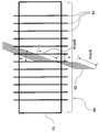
- the cutting length of the reinforcing fiber yarn 10 is such that when the interval between the disk blades 42 is P [mm] and the reinforcing fiber yarn 10 enters at an angle ⁇ [°], the reinforcing fiber yarn
- the cutting length of the strip 10 is P / sin ⁇ [mm]. That is, it is possible to control the cutting length arbitrarily and steplessly by changing the angle ⁇ [°] without changing the interval P [mm] of the disk blades 42.
- the traverse guide 20 When the traverse guide 20 is turned, in the process of switching the cutting angle from ⁇ [°] to - ⁇ [°], the angle ⁇ [°] approaches 0 ° and the cutting length becomes longer than P / sin ⁇ [mm].
- the fiber bundle 61 is cut out. If the cutting length becomes too long and the difference from the normal cutting length increases, adverse effects such as non-uniform quality may be considered.
- the traverse guide 20 is rapidly stopped at the end portion folding using the mechanism for arbitrarily adjusting the moving speed of the traverse guide 20 described above, and then folded back. It is preferable to shorten the time required for the cutting angle to switch from ⁇ [°] to ⁇ [°] by abrupt acceleration in the direction as much as possible.
- the cutting length can be changed by changing the angle ⁇ as described above, it is also preferable to increase the traverse traveling speed only at the folded portion at the end and to increase ⁇ . Since the cutting length is shortened by increasing ⁇ , the fiber length of the chopped fiber bundle 61 can be relatively shortened.
- the blade dense portion 44 in which the pitch P [mm] of the disk blades 42 is narrowed at the end of the cutter roll 40 that turns the traverse guide 20. Is preferably provided.
- a chopped fiber bundle 63 obtained by subdividing the chopped fiber bundle 61 can be obtained.
- an additional blade 45 arranged at the end of the cutter roll 40 for turning the traverse guide 20 so as to straddle adjacent disk blades 42.
- a chopped fiber bundle 64 in which the chopped fiber bundle 61 is forcibly divided can be obtained at the folded portion at the end of the cutter roll 40 where the fiber length tends to increase.
- the shape and arrangement of the additional blade 45 are not limited to a mode in which the adjacent disk blades 42 extend in a substantially orthogonal direction or are provided in a plurality of radial shapes.
- the cutter roll 40 and the nip roll 30 are traversed left and right substantially parallel to the rotation axis direction of the traverse guide 20 by the reciprocating drive mechanism.
- the same structure as above can be used.
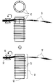
- FIG. A blade is attached to the outer edge, and a disk blade 42 having an opening for attachment at the center and a disk-shaped spacer 43 having an opening for attachment at the center are alternately arranged.
- the cutter roll 40 can be configured by inserting the roll main body 41 through the opening. With such a configuration, when the disk blade 42 is worn out, it is only necessary to replace the worn disk blade 42, so that the working time associated with the replacement of the disk blade 42 can be shortened and the replacement cost can be reduced. In particular, it is suitable for cutting high-strength reinforcing fibers that require rapid replacement of the disk blades 42, especially carbon fibers with particularly high hardness.
- the distance between the disk blades 42 can be easily and accurately changed by exchanging or rearranging the spacers 43. Furthermore, even if the plurality of cutter rolls 40 are not owned, it is possible to cope with various angles ⁇ [°] and fiber lengths P / sin ⁇ [mm] with one type of cutter roll 40. Furthermore, by changing the diameter of the disk blade 42 or the spacer 43, the amount of protrusion of the blade from the surface of the cutter roll 40 can be changed. Accordingly, it is possible to deal with the reinforcing fiber yarns 10 having various thicknesses.
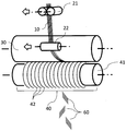
- FIG. 8 shows another embodiment of a manufacturing apparatus used for manufacturing a chopped fiber bundle according to the present invention.
- the 1st traverse roll 21 which pinches
- the 2nd traverse roll 22 which guides the reinforcing fiber yarn 10 to the nip roll 30 surface.
- the first traverse roll and the second traverse roll are connected to each other or move in synchronism with each other, and when the nip roll 30 and the cutter roll 40 reciprocate, they are fixed together, or at least one of them independently moves. Conceivable.
- FIG. 1st traverse roll 21 which pinches
- the 2nd traverse roll 22 which guides the reinforcing fiber yarn 10 to the nip roll 30 surface.
- the first traverse roll and the second traverse roll are connected to each other or move in synchronism with each other, and when the n
- the reinforcing fiber yarn 10 is guided to the surface of the second traverse roll 22 while being twisted between the first traverse roll 21 and the second traverse roll 22.
- the reinforcing fiber yarn 10 always receives a force so as to enter perpendicularly to the rotation axis of the downstream traverse roll 22, and as a result, the reinforcing fiber yarn 10 always has the second traverse roll. 22 is guided to travel at a certain position on 22. Thereafter, the reinforcing fiber yarns 10 on the second traverse roll 22 are guided in a form of being transferred to the surface of the nip roll 30.
- the second traverse roll 22 As a feature of this configuration, unlike the traverse guide 20 as shown in FIG. 1, since a roll or bar with a hook is not used, there is a point that the yarn width of the reinforcing fiber yarn 10 does not become narrow due to the hook.
- the distance between the first traverse roll 21 and the second traverse roll 22 is preferably as wide as possible in order to avoid the narrowing of the yarn due to twisting of the yarn. Further, it is preferable to provide a roll or a guide between the first traverse roll 21 and the second traverse roll 22 and twist it stepwise to avoid the narrowing of the yarn.
- the rolls other than the second traverse roll 22 are not limited to rolls, and various configurations such as a fixed guide can be used.
- FIG. 9 shows still another embodiment of a manufacturing apparatus used for manufacturing a chopped fiber bundle according to the present invention.
- the bobbin 12 is installed in the vicinity of the nip roll 30, and the reinforcing fiber yarn 11 on the outermost surface portion of the bobbin drawn from the bobbin 12 is introduced into the cutter in a manner of being transferred to the nip roll 30. Since the reinforcing fiber yarn 11 on the outermost surface portion of the bobbin is generally wound in an oblique direction with respect to the central axis of the bobbin, the position where the yarn is pulled out traverses in the axial direction of the bobbin as the yarn is pulled out. To move. If this traverse-like operation is used as it is, the yarn can be introduced in an oblique direction with respect to the cutter roll.
- FIG. 10 shows an example of the cleaning mechanism of the manufacturing apparatus used for manufacturing the chopped fiber bundle according to the present invention.
- the blade With the cutter roll having the shape in which straight blades are arranged in the roll circumferential direction and the cutter roll having the blades arranged in an oblique direction as described above as the existing technology, the blade is caught on or swept into the cleaning roll 46 and effectively wiped. It is difficult to take.
- the material of the cleaning roll 46 is not particularly limited, but by using a soft material such as rubber, it is possible to clean the cutter blade without damaging it, and to further bite the blade into the cleaning roll 46. As a result, the surface of the cleaning roll 46 also enters between the blades, so that the deposits clogged between the blades can be effectively wiped off.
- the same effect can be obtained by devising a groove in advance in the circumferential direction so as to avoid contact with the blade.
- the cleaning roll is not necessarily in contact with the cutter blade. Even if there is a certain interval, if the cleaning roll comes into contact with the deposit on the surface, the deposit will be flipped off, so that a cleaning effect can be obtained. Further, even when this cleaning roll 46 is applied to the nip roll 30, a high cleaning effect can be obtained similarly.
Landscapes
- Engineering & Computer Science (AREA)
- Life Sciences & Earth Sciences (AREA)
- Forests & Forestry (AREA)
- Mechanical Engineering (AREA)
- Textile Engineering (AREA)
- Chemical & Material Sciences (AREA)
- Geochemistry & Mineralogy (AREA)
- Manufacturing & Machinery (AREA)
- General Life Sciences & Earth Sciences (AREA)
- Materials Engineering (AREA)
- Organic Chemistry (AREA)
- Preliminary Treatment Of Fibers (AREA)
- Treatment Of Fiber Materials (AREA)
Abstract
Priority Applications (7)
| Application Number | Priority Date | Filing Date | Title |
|---|---|---|---|
| US15/740,114 US11110622B2 (en) | 2015-07-01 | 2016-06-10 | Device for manufcaturing chopped fiber bundle and method for manufacturing same |
| EP16817691.5A EP3318671B1 (fr) | 2015-07-01 | 2016-06-10 | Dispositif pour fabriquer un faisceau de fibres coupées et procédé de fabrication de celui-ci |
| KR1020187001698A KR102339964B1 (ko) | 2015-07-01 | 2016-06-10 | 촙드 섬유 다발의 제조 장치 및 그 제조 방법 |
| CN201680034961.1A CN107709653B (zh) | 2015-07-01 | 2016-06-10 | 短切纤维束的制造装置及其制造方法 |
| CA2991009A CA2991009A1 (fr) | 2015-07-01 | 2016-06-10 | Dispositif pour fabriquer un faisceau de fibres coupees et procede de fabrication de celui-ci |
| JP2016543104A JP6128455B1 (ja) | 2015-07-01 | 2016-06-10 | チョップド繊維束の製造装置およびその製造方法 |
| ES16817691T ES2884306T3 (es) | 2015-07-01 | 2016-06-10 | Dispositivo para fabricar haz de fibras cortadas y método para su fabricación |
Applications Claiming Priority (2)
| Application Number | Priority Date | Filing Date | Title |
|---|---|---|---|
| JP2015-132667 | 2015-07-01 | ||
| JP2015132667 | 2015-07-01 |
Publications (1)
| Publication Number | Publication Date |
|---|---|
| WO2017002582A1 true WO2017002582A1 (fr) | 2017-01-05 |
Family
ID=57607698
Family Applications (1)
| Application Number | Title | Priority Date | Filing Date |
|---|---|---|---|
| PCT/JP2016/067328 Ceased WO2017002582A1 (fr) | 2015-07-01 | 2016-06-10 | Dispositif pour fabriquer un faisceau de fibres coupées et procédé de fabrication de celui-ci |
Country Status (9)
| Country | Link |
|---|---|
| US (1) | US11110622B2 (fr) |
| EP (1) | EP3318671B1 (fr) |
| JP (1) | JP6128455B1 (fr) |
| KR (1) | KR102339964B1 (fr) |
| CN (1) | CN107709653B (fr) |
| CA (1) | CA2991009A1 (fr) |
| ES (1) | ES2884306T3 (fr) |
| TW (1) | TWI698562B (fr) |
| WO (1) | WO2017002582A1 (fr) |
Cited By (5)
| Publication number | Priority date | Publication date | Assignee | Title |
|---|---|---|---|---|
| JP2018059235A (ja) * | 2016-10-05 | 2018-04-12 | 東レ株式会社 | チョップド繊維束の製造装置 |
| JP2018058159A (ja) * | 2016-10-05 | 2018-04-12 | 東レ株式会社 | チョップド繊維束の製造装置および製造方法 |
| JP2020028954A (ja) * | 2018-08-23 | 2020-02-27 | 株式会社東京精密 | ファイバーケーブル切断装置 |
| JPWO2021177215A1 (fr) * | 2020-03-02 | 2021-09-10 | ||
| CN115198508A (zh) * | 2022-06-02 | 2022-10-18 | 台嘉玻璃纤维有限公司 | 一种切纱装置 |
Families Citing this family (10)
| Publication number | Priority date | Publication date | Assignee | Title |
|---|---|---|---|---|
| CN109385880B (zh) * | 2018-10-16 | 2021-04-20 | 宜城市天舒纺织有限公司 | 一种纺织用导纱切割装置 |
| CN111321488A (zh) * | 2018-12-13 | 2020-06-23 | 河南神玖天航新材料股份有限公司 | 一种铡刀式纤维短切机 |
| JP7297627B2 (ja) * | 2019-02-12 | 2023-06-26 | デクセリアルズ株式会社 | 刃及び刃の製造方法 |
| CN112048894B (zh) * | 2020-08-28 | 2021-07-16 | 安庆市花蕾纺织材料有限公司 | 一种熔喷布分切装置 |
| KR102193980B1 (ko) | 2020-10-21 | 2020-12-22 | 김민환 | 탄소 섬유 가닥 절단 장치 |
| CN114457470B (zh) * | 2022-02-10 | 2023-07-14 | 巢湖市强力渔业有限责任公司 | 一种渔网线生产用纤维定距裁剪装置 |
| CN116854363B (zh) * | 2023-07-06 | 2026-04-14 | 五河县维佳复合材料有限公司 | 一种用于静电玻璃纤维短切丝用防飞尘短切机 |
| CN121969792A (zh) | 2023-10-06 | 2026-05-01 | 加泽希姆复合材料集团 | 用于生产短切原丝以制造短切原丝毡的系统和方法 |
| CN117549375A (zh) * | 2023-11-28 | 2024-02-13 | 广西大学 | 一种纤维超声振动辅助短切平台 |
| CN119318410A (zh) * | 2024-10-22 | 2025-01-17 | 新华锦集团山东海川工艺发制品有限公司 | 一种幅度发束产品的制造方法 |
Citations (4)
| Publication number | Priority date | Publication date | Assignee | Title |
|---|---|---|---|---|
| JPH0741333A (ja) * | 1993-07-29 | 1995-02-10 | Nippon Electric Glass Co Ltd | 長繊維切断装置 |
| US5954278A (en) * | 1998-03-31 | 1999-09-21 | Etc. Industries, Inc. | Fiberglass cutting apparatus and method |
| JP2006200107A (ja) * | 2005-01-19 | 2006-08-03 | Smoother:Kk | 繊維束切断装置 |
| JP2008296408A (ja) * | 2007-05-29 | 2008-12-11 | Tokki Kk | 熱可塑性樹脂粒状物製造装置のカッタ |
Family Cites Families (19)
| Publication number | Priority date | Publication date | Assignee | Title |
|---|---|---|---|---|
| US2221869A (en) * | 1939-04-27 | 1940-11-19 | Celanese Corp | Device for producing staple fiber yarns from continuous filaments |
| BE505323A (fr) * | 1950-11-22 | 1900-01-01 | ||
| NL183255B (nl) * | 1952-12-03 | 1900-01-01 | Electroprint Inc | Stelsel met een regeldrukinrichting. |
| US3497920A (en) * | 1967-10-25 | 1970-03-03 | Turbo Machine Co | Apparatus and method for de-registering tow |
| US3768356A (en) * | 1972-06-05 | 1973-10-30 | Monsanto Co | Tow cutter |
| US3791247A (en) * | 1972-08-28 | 1974-02-12 | F Pretz | Paper trimming machine |
| US4043779A (en) * | 1976-03-08 | 1977-08-23 | Ppg Industries, Inc. | Apparatus for chopping coated glass fibers |
| US4347071A (en) * | 1978-11-24 | 1982-08-31 | Tba Industrial Products, Limited | Apparatus for production and cutting of glass fibres |
| US4885964A (en) * | 1984-09-14 | 1989-12-12 | Industrial Tools, Inc. | Tape slitter adjustment means |
| JPH05330846A (ja) * | 1992-06-04 | 1993-12-14 | Bando Chem Ind Ltd | ガラス繊維カット用刃受けロール |
| JP3456075B2 (ja) * | 1995-10-27 | 2003-10-14 | 日本電気硝子株式会社 | 長繊維の切断方法 |
| JP3980678B2 (ja) * | 1996-03-08 | 2007-09-26 | 富士フイルム株式会社 | 刃物位置切り替え制御方法 |
| US5970837A (en) * | 1996-12-18 | 1999-10-26 | Johns Manville International, Inc. | Chopper for cutting fiber continuously, and method |
| JP4154724B2 (ja) | 2001-11-27 | 2008-09-24 | 日本電気硝子株式会社 | ガラスチョップドストランド、及びガラス繊維不織布の製造方法 |
| JP2009114611A (ja) | 2007-10-16 | 2009-05-28 | Toray Ind Inc | チョップド繊維束および成形材料の製造方法、成形材料、繊維強化プラスチック |
| JP2009114612A (ja) | 2007-10-16 | 2009-05-28 | Toray Ind Inc | チョップド繊維束および成形材料の製造方法、成形材料、繊維強化プラスチック |
| CN203805055U (zh) * | 2014-04-19 | 2014-09-03 | 姚钟钟 | 一种玻璃纤维切割装置 |
| CN203794788U (zh) * | 2014-04-22 | 2014-08-27 | 全红英 | 一种玻璃纤维切割机构 |
| CN104355537A (zh) * | 2014-10-16 | 2015-02-18 | 宿迁市天彩玻璃纤维有限公司 | 一种玻璃纤维切割分散机 |
-
2016
- 2016-06-10 KR KR1020187001698A patent/KR102339964B1/ko active Active
- 2016-06-10 ES ES16817691T patent/ES2884306T3/es active Active
- 2016-06-10 JP JP2016543104A patent/JP6128455B1/ja active Active
- 2016-06-10 US US15/740,114 patent/US11110622B2/en active Active
- 2016-06-10 CN CN201680034961.1A patent/CN107709653B/zh active Active
- 2016-06-10 EP EP16817691.5A patent/EP3318671B1/fr active Active
- 2016-06-10 WO PCT/JP2016/067328 patent/WO2017002582A1/fr not_active Ceased
- 2016-06-10 CA CA2991009A patent/CA2991009A1/fr not_active Abandoned
- 2016-06-30 TW TW105120665A patent/TWI698562B/zh active
Patent Citations (4)
| Publication number | Priority date | Publication date | Assignee | Title |
|---|---|---|---|---|
| JPH0741333A (ja) * | 1993-07-29 | 1995-02-10 | Nippon Electric Glass Co Ltd | 長繊維切断装置 |
| US5954278A (en) * | 1998-03-31 | 1999-09-21 | Etc. Industries, Inc. | Fiberglass cutting apparatus and method |
| JP2006200107A (ja) * | 2005-01-19 | 2006-08-03 | Smoother:Kk | 繊維束切断装置 |
| JP2008296408A (ja) * | 2007-05-29 | 2008-12-11 | Tokki Kk | 熱可塑性樹脂粒状物製造装置のカッタ |
Non-Patent Citations (1)
| Title |
|---|
| See also references of EP3318671A4 * |
Cited By (9)
| Publication number | Priority date | Publication date | Assignee | Title |
|---|---|---|---|---|
| JP2018059235A (ja) * | 2016-10-05 | 2018-04-12 | 東レ株式会社 | チョップド繊維束の製造装置 |
| JP2018058159A (ja) * | 2016-10-05 | 2018-04-12 | 東レ株式会社 | チョップド繊維束の製造装置および製造方法 |
| JP2020028954A (ja) * | 2018-08-23 | 2020-02-27 | 株式会社東京精密 | ファイバーケーブル切断装置 |
| JP7132497B2 (ja) | 2018-08-23 | 2022-09-07 | 株式会社東京精密 | ファイバーケーブル切断装置 |
| JP2022164727A (ja) * | 2018-08-23 | 2022-10-27 | 株式会社東京精密 | ファイバーケーブル切断装置 |
| JP7397369B2 (ja) | 2018-08-23 | 2023-12-13 | 株式会社東京精密 | ファイバーケーブル切断装置 |
| JPWO2021177215A1 (fr) * | 2020-03-02 | 2021-09-10 | ||
| JP7743787B2 (ja) | 2020-03-02 | 2025-09-25 | 東レ株式会社 | 強化繊維複合材料 |
| CN115198508A (zh) * | 2022-06-02 | 2022-10-18 | 台嘉玻璃纤维有限公司 | 一种切纱装置 |
Also Published As
| Publication number | Publication date |
|---|---|
| EP3318671A4 (fr) | 2018-11-21 |
| CN107709653B (zh) | 2020-05-19 |
| CA2991009A1 (fr) | 2017-01-05 |
| ES2884306T3 (es) | 2021-12-10 |
| JP6128455B1 (ja) | 2017-05-17 |
| CN107709653A (zh) | 2018-02-16 |
| KR20180022814A (ko) | 2018-03-06 |
| TWI698562B (zh) | 2020-07-11 |
| US11110622B2 (en) | 2021-09-07 |
| KR102339964B1 (ko) | 2021-12-17 |
| EP3318671B1 (fr) | 2021-08-11 |
| TW201708657A (zh) | 2017-03-01 |
| US20180186020A1 (en) | 2018-07-05 |
| EP3318671A1 (fr) | 2018-05-09 |
| JPWO2017002582A1 (ja) | 2017-06-29 |
Similar Documents
| Publication | Publication Date | Title |
|---|---|---|
| JP6128455B1 (ja) | チョップド繊維束の製造装置およびその製造方法 | |
| JP7509193B2 (ja) | 断続的に分繊された連続炭素繊維束およびその製造方法 | |
| KR100696969B1 (ko) | 섬유속의 개섬방법 및 그 방법에 사용되는 장치 | |
| EP2969493B1 (fr) | Mécanisme de découpe | |
| US11794419B2 (en) | Fiber-reinforced resin molding material molded product and method of producing same | |
| JP6774651B2 (ja) | チョップド繊維束の製造装置 | |
| CN109890586B (zh) | 无序毡及其制造方法以及使用其的纤维增强树脂成型材料 | |
| JP2005161797A (ja) | プリプレグの製造方法および製造装置 | |
| EP1144288A2 (fr) | Procede de distribution de fibres de renfort | |
| KR102082632B1 (ko) | 보강 섬유 다발들의 제어된 침착을 위한 침착 디바이스 | |
| JP6764580B2 (ja) | チョップド繊維束の製造装置および製造方法 | |
| KR101928928B1 (ko) | 탄소 필라멘트 제조장치 | |
| JP7300910B2 (ja) | 開繊機構 | |
| JP4064995B2 (ja) | 繊維強化樹脂ストランドの製造装置 | |
| JP2018140486A (ja) | 強化繊維糸条切断装置 | |
| JP2022116765A (ja) | 開繊機構 | |
| CN121969792A (zh) | 用于生产短切原丝以制造短切原丝毡的系统和方法 | |
| JPH06254854A (ja) | 長繊維強化合成樹脂ストランドの製造方法 | |
| JP2006341473A (ja) | 長繊維強化熱可塑性樹脂成形材料の製造装置及びその製造方法 | |
| WO2011142658A2 (fr) | Procédé et système pour produire un mat de matière fibreuse |
Legal Events
| Date | Code | Title | Description |
|---|---|---|---|
| ENP | Entry into the national phase |
Ref document number: 2016543104 Country of ref document: JP Kind code of ref document: A |
|
| 121 | Ep: the epo has been informed by wipo that ep was designated in this application |
Ref document number: 16817691 Country of ref document: EP Kind code of ref document: A1 |
|
| ENP | Entry into the national phase |
Ref document number: 2991009 Country of ref document: CA |
|
| NENP | Non-entry into the national phase |
Ref country code: DE |
|
| ENP | Entry into the national phase |
Ref document number: 20187001698 Country of ref document: KR Kind code of ref document: A |