WO2017002878A1 - Dispositif d'élimination de substance étrangère, et véhicule équipé de celui-ci - Google Patents
Dispositif d'élimination de substance étrangère, et véhicule équipé de celui-ci Download PDFInfo
- Publication number
- WO2017002878A1 WO2017002878A1 PCT/JP2016/069335 JP2016069335W WO2017002878A1 WO 2017002878 A1 WO2017002878 A1 WO 2017002878A1 JP 2016069335 W JP2016069335 W JP 2016069335W WO 2017002878 A1 WO2017002878 A1 WO 2017002878A1
- Authority
- WO
- WIPO (PCT)
- Prior art keywords
- nozzle
- foreign matter
- pressure air
- lens
- vehicle
- Prior art date
- Legal status (The legal status is an assumption and is not a legal conclusion. Google has not performed a legal analysis and makes no representation as to the accuracy of the status listed.)
- Ceased
Links
Images











Classifications
-
- B—PERFORMING OPERATIONS; TRANSPORTING
- B60—VEHICLES IN GENERAL
- B60S—SERVICING, CLEANING, REPAIRING, SUPPORTING, LIFTING, OR MANOEUVRING OF VEHICLES, NOT OTHERWISE PROVIDED FOR
- B60S1/00—Cleaning of vehicles
- B60S1/02—Cleaning windscreens, windows or optical devices
- B60S1/56—Cleaning windscreens, windows or optical devices specially adapted for cleaning other parts or devices than front windows or windscreens
- B60S1/566—Cleaning windscreens, windows or optical devices specially adapted for cleaning other parts or devices than front windows or windscreens including wiping devices
-
- B—PERFORMING OPERATIONS; TRANSPORTING
- B60—VEHICLES IN GENERAL
- B60S—SERVICING, CLEANING, REPAIRING, SUPPORTING, LIFTING, OR MANOEUVRING OF VEHICLES, NOT OTHERWISE PROVIDED FOR
- B60S1/00—Cleaning of vehicles
- B60S1/02—Cleaning windscreens, windows or optical devices
- B60S1/56—Cleaning windscreens, windows or optical devices specially adapted for cleaning other parts or devices than front windows or windscreens
-
- B—PERFORMING OPERATIONS; TRANSPORTING
- B08—CLEANING
- B08B—CLEANING IN GENERAL; PREVENTION OF FOULING IN GENERAL
- B08B13/00—Accessories or details of general applicability for machines or apparatus for cleaning
-
- B—PERFORMING OPERATIONS; TRANSPORTING
- B08—CLEANING
- B08B—CLEANING IN GENERAL; PREVENTION OF FOULING IN GENERAL
- B08B5/00—Cleaning by methods involving the use of air flow or gas flow
- B08B5/02—Cleaning by the force of jets, e.g. blowing-out cavities
-
- B—PERFORMING OPERATIONS; TRANSPORTING
- B60—VEHICLES IN GENERAL
- B60S—SERVICING, CLEANING, REPAIRING, SUPPORTING, LIFTING, OR MANOEUVRING OF VEHICLES, NOT OTHERWISE PROVIDED FOR
- B60S1/00—Cleaning of vehicles
- B60S1/02—Cleaning windscreens, windows or optical devices
- B60S1/54—Cleaning windscreens, windows or optical devices using gas, e.g. hot air
-
- H—ELECTRICITY
- H04—ELECTRIC COMMUNICATION TECHNIQUE
- H04N—PICTORIAL COMMUNICATION, e.g. TELEVISION
- H04N7/00—Television systems
- H04N7/18—Closed-circuit television [CCTV] systems, i.e. systems in which the video signal is not broadcast
Definitions
- the present invention relates to a foreign matter removing device that ejects high pressure air to remove foreign matter, and a vehicle equipped with the foreign matter removing device.
- an injection device that injects high-pressure air requires a device for generating high-pressure air.
- such an injection device has a configuration in which external air is sucked from the tip of the nozzle and the air sucked in the device is compressed.
- the tip of the nozzle may be clogged with mud or dust, and it may be difficult to generate high-pressure air.
- it is necessary to take measures against clogging of the nozzle tip.
- An object of the present invention is to provide a foreign matter removing device capable of saving space and a vehicle including the foreign matter removing device.
- the foreign matter removing apparatus of the present invention comprises A foreign matter removing device for removing foreign matter on the lens of the in-vehicle camera attached to the vehicle so that the lens of the in-vehicle camera is exposed toward the outside of the body panel of the vehicle, A generator for generating high-pressure air; A nozzle unit having a nozzle that injects the high-pressure air toward the lens, and a mounting portion that is integrally formed with the nozzle and that can be attached to a housing of the in-vehicle camera; With In a state where the attachment portion is attached to the housing, the tip of the nozzle is positioned with respect to the lens.
- the nozzle is attached to the housing of the in-vehicle camera by the attachment portion formed integrally with the nozzle. For this reason, the tip of the nozzle can be accurately positioned with respect to the lens of the in-vehicle camera without using a dedicated bracket for attaching to the body panel of the vehicle, and the performance of removing foreign matters can be maintained.
- the attachment portion is attached to the housing of the in-vehicle camera in which the change in shape of each product is small compared to the body panel of the vehicle, versatility when attaching the foreign matter removing device to the vehicle is improved.
- the housing includes a first surface, a second surface that is continuous with one end of the first surface, a third surface that is located opposite to the second surface and is continuous with the other end of the first surface, Have In the state where the attachment portion is attached to the housing, the attachment portion is elastically deformable in a direction away from the opposing surface facing the first surface and the second surface, and is in contact with the second surface. You may have a contact part and the 2nd contact part which contacts the said 3rd surface while being elastically deformable toward the direction away from the said 3rd surface.
- the mounting portion of the nozzle unit is fixed to the housing while being deformed along the outer shape of the housing of the in-vehicle camera. For this reason, the tip of the nozzle can be positioned more accurately with respect to the lens of the in-vehicle camera.
- the first surface of the housing and the facing surface of the mounting portion may be bonded to each other through an adhesive member.
- the mounting portion of the nozzle unit is firmly fixed to the in-vehicle camera housing via the adhesive member. For this reason, the tip of the nozzle can be positioned more accurately with respect to the lens of the in-vehicle camera.
- the foreign matter removing apparatus of the present invention is The housing and the attachment portion may be configured to be engageable with each other.
- the mounting portion of the nozzle unit is fixed while being engaged with the housing of the in-vehicle camera. For this reason, the tip of the nozzle can be positioned more accurately with respect to the lens of the in-vehicle camera.
- the housing has a camera front surface in which a lens hole for exposing the lens is formed
- the nozzle may include a positioning portion that is positioned with respect to the camera front surface in contact with the camera front surface in a state where the attachment portion is attached to the housing.
- the tip of the nozzle can be accurately positioned in the front-rear direction of the camera with respect to the lens of the in-vehicle camera.
- the generator has a discharge port for discharging the high-pressure air
- the nozzle has an inlet through which the high-pressure air flows, further, A hose connecting the outlet and the inlet; While connecting the hose and the nozzle, a joint member capable of changing the attitude with respect to the nozzle, May be provided.
- the orientation of the hose can be changed by changing the posture of the joint member that is a separate component from the nozzle, and the versatility when attaching the foreign matter removing device to the vehicle is improved.
- the tip of the nozzle may be positioned so as to face the center of the lens.
- the foreign matter removing apparatus of the present invention is A foreign matter removing device that removes foreign matter on the camera lens attached so that the camera lens is exposed to the outside of the panel member, A generator for generating high-pressure air; A nozzle unit having a nozzle that injects the high-pressure air toward the lens, and a mounting portion that is integrally formed with the nozzle and that can be attached to the housing of the camera; With In a state where the attachment portion is attached to the housing, the tip of the nozzle is positioned with respect to the lens.
- the nozzle is attached to the camera housing by the attachment portion formed integrally with the nozzle. Therefore, the tip of the nozzle can be accurately positioned with respect to the camera lens without using a dedicated bracket for attaching to the panel member, and the performance of removing foreign matter can be maintained. Moreover, since the attachment portion is attached to the camera housing in which the change in shape of each product is small compared to the panel member, versatility is improved.
- the foreign matter removing apparatus of the present invention is A foreign matter removing device for removing foreign matter adhering to a partition wall interposed between an in-vehicle sensor and a measurement target of the in-vehicle sensor, A generator for generating high-pressure air; A nozzle unit having a nozzle that injects the high-pressure air toward the partition; and a mounting unit that is integrally formed with the nozzle and that can be attached to a housing of the in-vehicle sensor; With In a state where the attachment portion is attached to the housing, the tip of the nozzle is positioned with respect to the partition wall.
- the foreign matter removing apparatus of the present invention includes: A foreign matter removing device for removing foreign matter on the lens of the in-vehicle camera attached to the vehicle so that the lens of the in-vehicle camera is exposed toward the outside of the body panel of the vehicle, A generator for generating high-pressure air; A nozzle for injecting the high-pressure air toward the lens; With The nozzle has an inflow port through which high-pressure air flows, a spout through which high-pressure air is ejected, and a communication path that connects the inflow port and the spout. The communication path communicates with a bypass path through an opening smaller than the jet port.
- the bypass path may be formed to join the communication path in an acute angle direction from the rear with respect to the direction in which the high-pressure air flows.
- the bypass path is formed at an acute angle with respect to the direction in which the high-pressure air flows through the communication path. For this reason, the high-pressure air flowing toward the injection port during the injection hardly flows out from the opening, and the performance of removing foreign matters is maintained.
- the generator has a discharge port for discharging the high-pressure air, further, A hose connecting the outlet and the inlet of the nozzle; A connecting portion for connecting the hose and the nozzle; With A groove may be provided on the outer peripheral surface of the connecting portion, and the groove may serve as the bypass path in a state where the connecting portion is fitted to the inlet of the nozzle.
- the bypass path can be simply configured using the connecting portion that connects the hose and the nozzle.
- the generator has a discharge port for discharging the high-pressure air, further, A hose connecting the outlet and the inlet of the nozzle; A connecting portion for connecting the hose and the nozzle; With The opening of the connecting portion is smaller than the inlet of the nozzle, In a state where a part of the connecting portion is inserted into the inlet of the nozzle, a gap is formed between the outer peripheral surface of the connecting portion and the inner peripheral surface of the inlet, and the gap is the bypass path. It may be.
- the bypass path can be simply configured using the connecting portion that connects the hose and the nozzle.
- the foreign matter removing apparatus of the present invention is A foreign matter removing device for removing foreign matter on a lens, A generator for generating high-pressure air; A nozzle for injecting the high-pressure air toward the lens; With The nozzle has an inflow port through which high-pressure air flows, a spout through which high-pressure air is ejected, and a communication path that connects the inflow port and the spout.
- the communication path communicates with a bypass path through an opening smaller than the jet port.
- the foreign matter removing apparatus of the present invention is A foreign matter removing device for removing foreign matter adhering to a partition wall interposed between an in-vehicle sensor and a measurement target of the in-vehicle sensor, A generator for generating high-pressure air; A nozzle that injects the high-pressure air toward the partition; With The nozzle has an inflow port through which high-pressure air flows, a spout through which high-pressure air is ejected, and a communication path that connects the inflow port and the spout. The communication path communicates with a bypass path through an opening smaller than the jet port.
- the generator has a piston
- the time for the piston in the generating unit to move from the top dead center to the bottom dead center may be 10 times or more the time for the piston to move from the bottom dead center to the top dead center.
- the piston in the generating unit is in the direction of the retentive force in which the speed in the sending direction, which is the moving direction when sending air, is opposite to the sending direction and is the moving direction when sucking in air.
- the speed at which the air in the communication path moves is also faster during exhaust than during intake. According to this, while ensuring the bypass function of the bypass path, the amount of high-pressure air flowing out from the bypass path during exhaust (injection) can be reduced, and the foreign matter removal performance during injection can be maintained.
- the foreign matter removing apparatus includes: A foreign matter removing device for removing foreign matter on the lens of the in-vehicle camera attached to the vehicle so that the lens of the in-vehicle camera is exposed toward the outside of the body panel of the vehicle, A generator for generating high-pressure air; A nozzle for injecting the high-pressure air toward the lens, The tip of the nozzle includes a first wall that faces the front surface of the in-vehicle camera.
- the tip of the nozzle includes the first wall portion facing the front surface of the in-vehicle camera.
- the shape of the nozzle may be configured such that the high-pressure air that has flowed into the nozzle from the generation unit is jetted toward the lens while being applied to the first wall portion.
- the high-pressure air can be rectified by sending the high-pressure air against the first wall portion, and high-pressure air with an appropriate air volume can be sent to an appropriate location on the lens surface.
- the tip of the nozzle may include a pair of second wall portions that extend from both side surfaces of the first wall portion toward the lens.
- the air blown from the nozzle can be more efficiently guided to the lens.
- the pair of second wall portions has a shape conforming to the shape of the front surface of the in-vehicle camera,
- the nozzle may be attached to the in-vehicle camera so that the pair of second wall portions are in contact with the front surface.
- the first wall portion, the second wall portion, and the front surface of the camera can form a pipe line that covers the entire peripheral surface of the high-pressure air outlet, so that the air blown from the nozzle is more efficient. Therefore, the nozzle can be accurately positioned with respect to the lens of the camera.
- the first wall portion may have a shape expanded in a fan shape toward the lens.
- high-pressure air can be sprayed substantially uniformly toward the entire outer surface of the lens.
- the surface of the first wall facing the front surface of the in-vehicle camera may be provided with at least one protrusion for rectifying the high-pressure air and spraying it on the lens.
- the projection direction can control the injection direction, amount, pressure, and the like of the high-pressure air at the nozzle tip to efficiently blow it with the lens.
- a foreign matter removing apparatus for removing foreign matter on the lens of the in-vehicle camera attached to the vehicle so that the lens of the in-vehicle camera is exposed toward the outside of the body panel of the vehicle,
- the nozzle is attached to the in-vehicle camera so that the pair of second wall portions are in contact with the front surface, At least one protrusion for rectifying the cleaning liquid and discharging it toward the lens is provided on a surface of the first wall facing the front surface.
- the ejection direction, the flow rate, the pressure, and the like of the cleaning liquid at the nozzle tip can be controlled by the protrusion, and the lens can be efficiently sprayed.
- the foreign matter removing apparatus of the present invention is A foreign matter removing device for removing foreign matter on a camera lens, A generator for generating high-pressure air; A nozzle for injecting the high-pressure air toward the lens; With The tip portion of the nozzle includes a first wall portion facing the lens.
- the tip portion of the nozzle includes the first wall portion facing the lens.
- the foreign matter removing apparatus of the present invention is A foreign matter removing device for removing foreign matter adhering to a partition wall interposed between an in-vehicle sensor and a measurement target of the in-vehicle sensor, A generator for generating high-pressure air; A nozzle that injects the high-pressure air toward the partition; With The tip of the nozzle has a first wall that faces the partition.
- the vehicle of the present invention includes the above-described foreign matter removing device.
- the foreign matter on the lens can be removed by blowing high-pressure air.
- the accuracy of the information obtained can be increased.
- the foreign matter removing device of the present invention and the vehicle equipped with the foreign matter removing device, it is possible to improve versatility when attaching the foreign matter removing device to the vehicle while maintaining the performance of removing the foreign matter. Moreover, even when the tip of the nozzle is clogged, high-pressure air can be generated, and space can be saved when the nozzle is attached to the vehicle.
- (A) is a rear view of the vehicle (foreign matter removing device is shown in perspective)
- (b) is a side view of the rear part of the vehicle (foreign matter removing device is shown in perspective)
- (c) is a vehicle It is the elements on larger scale of the rear part.
- (A) is a figure which shows another example of the position where a foreign material removal apparatus is attached.
- It is a perspective view of a foreign substance removal device concerning a first embodiment of the present invention.
- FIG. 10 is a cross-sectional view taken along line AA in FIG. 9.
- FIG. 10 is a longitudinal sectional view taken along line BB in FIG. 9.
- (A), (b) is sectional drawing for demonstrating the bypass path
- FIG. 14 is a cross-sectional view taken along the line CC of FIG. 13.
- FIG. 15A is a cross-sectional view taken along the line DD of FIG. 14, and
- FIG. 15B is a perspective view of the joint member viewed from the lower surface side.
- (A) is a perspective view for demonstrating another modification (modification 3) of a bypass path.
- FIG. 17 is a longitudinal sectional view taken along line EE in FIG. 16. It is a graph which shows the time change of the flow volume of the high pressure air injected from a nozzle. It is a perspective view of the foreign material removal apparatus which concerns on 3rd embodiment of this invention. It is a disassembled perspective view which shows the nozzle unit and joint member which concern on 3rd embodiment.
- FIG. 21 It is a perspective view which shows the nozzle unit attached to the vehicle-mounted camera of FIG. It is a side view which shows the attachment state of the nozzle unit with respect to a vehicle-mounted camera.
- A) is a longitudinal sectional view taken along line FF in FIG. 21, and
- (b) is a transverse sectional view taken along line GG in FIG. It is a perspective view for demonstrating the modification (modification 4) of the nozzle with which a nozzle unit is provided.
- (A) is a side view of the state in which the nozzle unit of FIG. 24 is attached to the in-vehicle camera
- (b) is a longitudinal sectional view taken along the line HH of FIG.
- the foreign matter removing device of the present invention is applied as a device that removes foreign matter such as water droplets, mud and dust adhering to the lens of the vehicle-mounted camera.
- the foreign matter removing apparatus 1 is attached to a back door 200A of the vehicle V, for example.
- the foreign matter removing apparatus 1 includes a motor 55, and a power terminal of the motor 55 is connected to a power line of the vehicle.
- the vehicle control unit (ECU) (not shown) starts shooting by an in-vehicle camera 100 described later, and the foreign matter removing device 1 is, for example, within a few seconds at the start of shooting. It is controlled to operate by a vehicle control unit (ECU).
- the in-vehicle camera 100 is a camera for confirming, for example, the rear of the vehicle V, and the lens 101 of the in-vehicle camera 100 is exposed toward the outside of the back door 200A of the vehicle V as shown in FIG. Is attached to the back door 200A.
- the in-vehicle camera 100 has an imaging unit (not shown), and the lens 101 covers the imaging unit.
- the lens 101 includes a simple translucent cover that does not converge or diffuse light.
- the foreign material removal apparatus 1 may be attached to the rear bumper 200B of the vehicle V, for example, as shown to Fig.2 (a), (b).
- the position where the in-vehicle camera 100 is attached is not limited to the rear end side of the vehicle, and may be a body panel on the front side or side side of the vehicle.
- the meaning of “attached to the body panel” means, for example, when the in-vehicle camera is attached via a vehicle cover part such as a lamp, a door knob, a mirror, or a bumper attached to the body panel. Is included as a part of these parts (as an integral part).
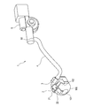
- the foreign matter removing apparatus 1 includes a nozzle unit 2, a joint member 3, a hose 4, and a high-pressure air generation unit (an example of a generation unit) 5.
- the nozzle unit 2 is configured to be detachable from the in-vehicle camera 100, and includes an attachment portion 21 and a nozzle 22.
- the nozzle unit 2 is made of, for example, resin.
- the attachment portion 21 is attached to the housing 102 of the in-vehicle camera 100 so as to cover the upper surface of the in-vehicle camera 100.
- the nozzle 22 injects high-pressure air toward the lens 101 of the in-vehicle camera 100.
- the nozzle 22 is formed integrally with the attachment portion 21, and is provided so that the tip (injection port) of the nozzle 22 faces the lens 101 when the attachment portion 21 is attached to the housing 102.
- integralally formed means that the operator can handle the nozzle 22 and the attachment portion 21 as an integral part during assembly work.
- the nozzle 22 and the attachment portion 21 may be formed with the same material and the same mold, or the nozzle 22 and the attachment portion 21 may be formed with different materials and fitted to each other.
- the nozzle unit 2 may be formed integrally.
- the joint member 3 is a member that joins the nozzle 22 and the hose 4 of the nozzle unit 2, and has one end connected to the nozzle 22 and the other end connected to the hose 4.
- the joint member 3 is made of, for example, resin.
- the hose 4 is a piping member that connects the nozzle 22 and the high-pressure air generation unit 5 together with the joint member 3. One end of the hose 4 is connected to the joint member 3, and the opposite end is connected to the discharge port 50 of the high-pressure air generation unit 5.
- the hose 4 is made of a material such as resin or rubber.
- the high-pressure air generation unit 5 is a unit for generating high-pressure air to be sent to the nozzle 22.
- the high pressure air generation unit 5 is attached to a part of the vehicle body inside the vehicle.
- the high-pressure air generation unit 5 includes a case main body 51 and a moving mechanism disposed inside the case main body 51.
- the moving direction of the piston 52 is the sending direction in the rear, which is the direction in which the air is sent out, and the accumulating force direction is in the direction opposite to the sending direction.
- the piston 52 In an initial state before high-pressure air is sent out, the piston 52 is positioned on the delivery direction side, and the rack 53 is positioned in a state where the rack portion 53a can mesh with the gear portion 54a of the pinion 54.
- the air (outside air) that has flowed into the front half portion (second space) 60b of the internal space 60 of the piston support portion 59 passes through the gap 61b along the step 61a. It flows through the inner space 60 toward a substantially half portion (first space) 60a on the rear side.
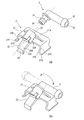
- the mounting portion 21 of the nozzle unit 2 has a substantially rectangular top plate 21A and two side plates 21B and 21C.
- the side plate 21B is provided so as to protrude from the lower surface side of the top plate 21A continuously to one end of the top plate 21A.
- the side plate 21C is located on the side opposite to the side plate 21B, and is provided so as to protrude from the lower surface side of the top plate 21A continuously to the other end of the top plate 21A.
- the side plate 21B and the side plate 21C are curved so that the respective contact portions 21D and 21E protrude slightly inward, and the lower end portion 21F and the lower end portion 21G slightly extend outward. Inclined. A material having excellent elasticity is used for the resin constituting the mounting portion 21.
- the nozzle 22 of the nozzle unit 2 has a connecting portion 22A, an extending portion 22B, and an ejection portion 22C.
- the connecting portion 22A is a portion to which the joint member 3 is connected.
- the connecting portion 22A is provided with an inflow port 23 through which high-pressure air flows.
- the extending portion 22B is a portion that connects the connecting portion 22A and the ejection portion 22C.
- the jet part 22C is a part from which high-pressure air is jetted, and is provided with a jet port 24 that opens horizontally (for example, rectangular, elliptical, etc.).
- the high-pressure air that has flowed into the inlet 23 of the connecting portion 22A is ejected from the outlet 24 of the ejecting portion 22C through the connecting portion 22A, the extending portion 22B, and the communication path formed in the ejecting portion 22C.
- the nozzle 22 is disposed at the center of the mounting portion 21 on the top plate 21A.
- the joint member 3 is formed of a cylindrical member having an L shape, and has a connecting portion 31 connected to the nozzle 22 and a connecting portion 32 connected to the hose 4.
- the connection part 32 is provided with an inflow port 33 into which high-pressure air flows.
- the connecting portion 31 is provided with an outlet 34 through which high-pressure air flows out.
- a connection path that connects the inflow port 33 and the outflow port 34 is formed in the joint member 3.
- the joint member 3 is connected to the nozzle 22 as shown in FIG. 5B by fitting the connecting portion 31 into the inlet 23 of the nozzle 22. In a state where the joint member 3 is connected to the nozzle 22, the joint member 3 can rotate about the connecting portion 31 to change the posture with respect to the nozzle 22.
- the housing 102 of the in-vehicle camera 100 is formed in a cubic shape, for example.
- the housing 102 is positioned on the opposite side of the upper surface (an example of the first surface) 102A, the right side surface (an example of the second surface) 102B continuous with one end of the upper surface 102A, and the other side of the upper surface 102A.
- the left side surface (an example of the third surface) 102C is formed in a cubic shape, for example.
- the nozzle unit 2 is attached to the in-vehicle camera 100 so that the attachment portion 21 is fitted into the housing 102 from above.
- the inner surface (an example of the opposite surface) of the top plate 21 ⁇ / b> A faces the upper surface 102 ⁇ / b> A of the housing 102.
- the top plate 21A is bonded to the upper surface 102A of the housing 102 via an adhesive member 25 such as an adhesive or a double-sided tape.
- the side plate 21B is elastically deformable in a direction away from the right side surface 102B of the housing 102, and contacts the right side surface 102B at a contact portion (an example of a first contact portion) 21D of the side plate 21B.
- the side plate 21C comes into contact with the left side surface 102C and presses the left side surface 102C at a contact portion (an example of a second contact portion) 21E.
- a contact portion an example of a second contact portion
- the nozzle 22 is disposed toward the lens 101 so that the extending portion 22B is along the shoulder on the front surface of the housing 102, and is positioned so that the jet outlet 24 of the jet portion 22C faces the center 101A of the lens 101.
- the joint member 3 is connected to the hose 4 at the connecting portion 32.
- the high-pressure air flows into the inlet 23 (see FIG. 5) of the nozzle 22 and is ejected from the ejection port 24 through the communication path.
- High-pressure air ejected from the ejection port 24 is blown toward the lens 101 of the in-vehicle camera 100. Thereby, the foreign matter adhering to the lens 101 is blown away, and the dirt of the lens 101 is eliminated.
- the camera and the nozzle are respectively attached to the vehicle body panel. It must be positioned while. In this case, an attachment error occurs in each of the camera and the nozzle, and the sum of the two errors results in a displacement of the nozzle relative to the camera lens.
- the shape of the body panel (appearance) of the vehicle is various, it is necessary to prepare a dedicated bracket depending on the manufacturer and vehicle type, and the versatility when attaching to the vehicle is low.
- the nozzle 22 is formed integrally with the attachment portion 21, and the attachment portion 21 is attached to the housing 102 of the in-vehicle camera 100. Since it is not necessary to position the nozzle 22 by attaching it to the body panel of the vehicle, the tip of the nozzle 22 can be accurately positioned with respect to the lens 101 of the in-vehicle camera 100, and the performance of removing foreign matter adhering to the lens 101 is achieved. Can be increased.
- the nozzle unit 2 is configured such that when the attachment portion 21 is attached to the housing 102 of the in-vehicle camera 100, the jet port 24 of the nozzle 22 faces the center of the lens 101. For this reason, the positioning accuracy of the nozzle 22 with respect to the lens 101 of the in-vehicle camera 100 can be further improved, and the performance of removing foreign matter can be enhanced.
- the top plate 21 ⁇ / b> A is bonded to the housing 102 with the adhesive member 25, and the side plates 21 ⁇ / b> B and 21 ⁇ / b> C are elastically deformed to come into contact with the housing 102.
- the attachment portion 21 is firmly fixed to the housing 102 by the adhesive member 25 and is fixed to the housing 102 of the in-vehicle camera 100 in a state of being deformed along the shape of the housing 102. Therefore, the jet port 24 of the nozzle 22 can be positioned more accurately with respect to the lens 101 of the in-vehicle camera 100, and the performance of removing foreign matter can be enhanced.
- the shape of the housing 102 of the in-vehicle camera 100 to which the mounting portion 21 is attached is smaller in the size of each product compared to the shape of the vehicle body panel. Since the side plates 21B and 21C can be elastically deformed and attached to cameras with slightly different left and right widths of the housing 102, it is not necessary to prepare a dedicated bracket or the like, and the foreign matter removing apparatus 1 is attached to the vehicle. Versatility can be improved.
- the joint member 3 connected to the nozzle 22 is configured so that the posture with respect to the nozzle 22 can be changed. Therefore, the joint member 3 can be connected to the hose 4 by changing the posture of the joint member 3 even when the location of the high-pressure air generating unit 5 in the vehicle varies depending on the vehicle type. Therefore, the nozzle unit 2 and the high pressure air generation unit 5 can be easily connected via the joint member 3, and the versatility when the foreign matter removing apparatus 1 is attached to the vehicle can be further improved.
- the nozzle 22 can be attached to the vehicle-mounted camera 100 via the nozzle unit 2 without using a dedicated bracket, an increase in product cost can be suppressed.
- the attachment portion 71 of the modification is different in structure of the side plate 71B and the side plate 71C from the attachment portion 21 (see FIG. 7).
- the repeated description is abbreviate
- the side plate 71B is provided so as to extend in a direction perpendicular to the top plate 21A on the lower surface side of the top plate 21A continuously from one end of the top plate 21A.
- the side plate 71C is located on the opposite side of the side plate 71B, and is provided so as to extend in a direction perpendicular to the top plate 21A on the lower surface side of the top plate 21A continuously to the other end of the top plate 21A. It has been.
- the side plate 71B and the side plate 71C can be elastically deformed in a direction away from the right side surface 102B and the left side surface 102C of the housing 102, respectively.
- the side plate 71B and the side plate 71C are provided with a convex portion 71F and a convex portion 71G at the lower end 71D and the lower end 71E, respectively.
- the convex portion 71F and the convex portion 71G are provided so as to face each other inside the side plate 71B and the side plate 71C.
- the convex part 71F and the convex part 71G are provided so that it may extend in the width direction of the side plate 71B and the side plate 71C, for example.
- the left side surface 102C and the right side surface 102B of the housing 102 are provided with a recess 102G and a recess 102F.
- the distance h from the upper surface 102A of the housing 102 to the concave portion 102G and the concave portion 102F is configured to be equal to the distance H from the lower surface of the top plate 21A of the mounting portion 71 to the convex portion 71F and the convex portion 71G.
- the mounting portion 71 of the nozzle unit 2 is engaged with the concave portion 102G and the concave portion 102F of the housing 102, respectively, with respect to the housing 102 of the in-vehicle camera 100.
- the side plate 71B and the side plate 71C are fixed in surface contact with the housing 102.
- tip of the nozzle 22 can be positioned more accurately with respect to the lens 101 of the vehicle-mounted camera 100 in the front-rear and left-right directions of the camera.
- an engagement configuration in which a convex portion is provided on the housing 102 and a concave portion is provided on the side plate may be employed.
- FIG. 9 shows the nozzle unit 2 ⁇ / b> A attached to the in-vehicle camera 100.
- 10 shows a cross-sectional view taken along the line AA in FIG. 9, and
- FIG. 11 shows a vertical cross-sectional view taken along the line BB in FIG.
- the nozzle 82 of the modified example is different from the nozzle 22 (see FIG. 6) in the structure of the ejection part 82C.
- the repeated description is abbreviate
- the nozzle unit 2 ⁇ / b> A includes a mounting portion 21 and a nozzle 82.
- the nozzle 82 has a connecting portion 22A, an extending portion 22B, and an ejection portion 82C.
- the ejection part 82C is a part from which high-pressure air is ejected, and is provided with an ejection port 24.
- the high-pressure air flowing into the inflow port 23 is ejected from the ejection port 24 through a communication path formed by the connecting portion 22A, the extending portion 22B, and the ejection portion 82C.
- the housing 102 of the in-vehicle camera 100 has a front surface (an example of the camera front surface) 102H that is continuous with one end of each of the upper surface 102A, the right side surface 102B, and the left side surface 102C.
- the front surface 102H is a planar view region when the housing 102 is viewed from the front as a single unit.
- a lens hole 102K through which the lens 101 is exposed is formed on the front surface 102H.
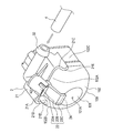
- the ejection part 82 ⁇ / b> C has a top wall 91 that faces the front surface 102 ⁇ / b> H of the housing 102, and two side walls 92 and 93.
- the side wall 92 is provided so as to continuously extend from the one end of the top wall 91 in a direction away from the top wall 91.
- the side wall 93 is located on the opposite side of the side wall 92, and is provided so as to continuously extend from the other end of the top wall 91 in a direction away from the top wall 91.
- the ejection portion 82 ⁇ / b> C of the nozzle 82 is configured by the top wall 91 and the side walls 92 and 93, and a wall (bottom wall) facing the top wall 91 is not formed.
- the nozzle 82 is configured such that the side walls 92 and 93 (an example of a positioning portion) of the ejection portion 82 ⁇ / b> C are in contact with the front surface 102 ⁇ / b> H of the housing 102 in a state where the attachment portion 21 is attached to the housing 102 of the in-vehicle camera 100. (See FIG. 10). When the side walls 92 and 93 are in contact with the front surface 102H, the position of the nozzle 82 with respect to the front surface 102H of the housing 102 is determined.
- a communication passage 94 surrounded by the top wall 91, the side walls 92 and 93, and the front surface 102H of the housing 102 is formed in the ejection portion 82C (see FIG. 11).
- the high-pressure air is ejected from the ejection port 24 through the communication path 94.
- the nozzle unit 2A is fixed to the housing 102 of the in-vehicle camera 100 by the mounting portion 21 and is also fixed by the side walls 92 and 93 of the nozzle 82.
- the tip of the nozzle 82 can be accurately positioned with respect to the lens 101 of the in-vehicle camera 100 not only in the left-right direction but also in the front-rear direction of the camera.
- the ejection portion 82C has no bottom wall, the thickness of the nozzle 82 can be reduced, and the increase in size of the nozzle unit 2A can be suppressed.
- FIG. 12A and 12B are cross-sectional views for explaining a bypass path formed in a nozzle included in the foreign matter removing apparatus according to the second embodiment.
- the nozzle 122 provided in the foreign matter removing apparatus according to the second embodiment includes a communication path 71 that connects the inflow port 23 and the ejection port 24, and a lower wall 72 of the extending portion 22 ⁇ / b> B.
- a bypass path 73 is formed therethrough.
- the communication path 71 includes a pipe 71a of the connecting portion 22A, pipes 71b and 71c of the extending portion 22B, and a pipe 71d of the ejection portion 22C.
- the pipe line 71b means a pipe line from the end of the pipe line 71a to a place where the bypass path 73 is formed, and the pipe line 71c is a path from the place where the bypass path 73 is formed to the beginning of the pipe line 71d.
- the cross-sectional area of the pipe 71c (the cross-sectional area of the cross section orthogonal to the flow: an example of the size of the pipe) is slightly larger than the cross-sectional area of the pipe 71b.
- the cross-sectional area of the pipe line 71d (jet port 24) is formed to be the same as the cross-sectional area of the pipe line 71c.
- the cross-sectional area of the pipe line 71a is formed larger than the cross-sectional area of the pipe line 71d.
- the inner diameter of the pipe 71 a is the same as the outer diameter of the connecting portion 31 of the joint member 3 fitted into the inflow port 23.
- the magnitude relationship of a pipe line and each opening may be prescribed
- the bypass path 73 communicates with the communication path 71 through an opening 74 formed in the lower wall 72.
- the sectional area of the bypass path 73 is formed to be the same size as the sectional area of the opening 74.
- the opening 74 is formed to be smaller than the cross-sectional area of the pipe 71d (jet port 24) and the cross-sectional area of the pipe 71b.
- the bypass path 73 is formed to have an acute angle ⁇ with respect to the lower wall 72.
- An arrow X in FIG. 12A indicates the direction in which high-pressure air flows in the communication path 71.
- the bypass path 73 is formed so as to merge in the acute angle direction from the rear with respect to the direction of the arrow X.
- the high-pressure air flows into the inflow port 23 of the nozzle 122 as shown in FIG. 12A, and is ejected from the ejection port 24 through the communication path 71 as indicated by an arrow X.
- the jet outlet 24 is formed larger than the opening 74, and the bypass passage 73 is formed in an acute angle ( ⁇ ) direction with respect to the direction in which the high pressure air flows. Sent out as indicated by X.
- the high-pressure air ejected from the ejection port 24 is blown toward the lens 101 of the in-vehicle camera 100. Thereby, the foreign matter adhering to the lens 101 is blown away, and the dirt of the lens 101 is eliminated.
- the air sucked into the high-pressure air generating unit 5 is indicated by an arrow Y in FIG. As shown, the air flows in from the bypass port 75 and is sucked into the high-pressure air generating unit 5 through the bypass path 73 and the communication path 71.
- the nozzle 122 is provided with the spout 24 and the bypass path 73 communicating with the communication path 71 via the opening 74. For this reason, even if the nozzle 24 is temporarily clogged, the outside air (air) for generating high-pressure air can be sucked through the bypass path 73. Thereby, even if the clogging occurs in the ejection port 24, high-pressure air can be generated, and the clogging of the ejection port 24 is eliminated by the generated high-pressure air, and a good ejection state of the high-pressure air is ensured. be able to.
- the opening 74 of the bypass path 73 is formed smaller than the ejection port 24 of the nozzle 122, the high-pressure air flowing toward the ejection port 24 during the injection hardly flows out from the opening 74. For this reason, even if the bypass path 73 is provided in the nozzle 122 in addition to the ejection port 24, the performance of the nozzle 122 to remove foreign matters is maintained.
- the bypass path 73 is formed at an acute angle ( ⁇ ) with respect to the direction in which the high-pressure air flows through the communication path 71 (the direction of the arrow X shown in FIG. 12A). For this reason, the high-pressure air flowing toward the jet outlet 24 during the injection hardly flows in the direction of the bypass path 73 and hardly flows out from the opening. For this reason, even if the bypass path 73 is provided in addition to the ejection port 24, the performance of removing foreign matter by the nozzle 122 is maintained.
- FIG. 13 shows a nozzle unit 2 attached to the in-vehicle camera 100 and a joint member (an example of a connecting portion) 3A connected to the nozzle 22 of the nozzle unit 2.
- FIG. 14 is a longitudinal sectional view taken along the line CC in FIG.
- FIG. 15A shows a cross-sectional view taken along the line DD in FIG. 14, and
- FIG. 15B shows a nozzle side connecting portion 31A (referred to as a nozzle connecting portion in this example) 31A of the joint member 3A from the lower surface side. A perspective view is shown.
- the bypass path 73A of Modification 2 is different from the bypass path 73 (see FIG. 12) formed through the lower wall 72 of the nozzle 122 in that it is formed in the nozzle connecting portion 31A of the joint member 3A. Yes.
- the repeated description is abbreviate
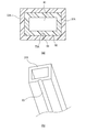
- the nozzle connecting portion 31A of the joint member 3A of this example has a rectangular cross section as shown in FIG. Further, a rectangular connecting path 81 (a path connecting the inflow port 33 and the outflow port 34) is formed in the nozzle connecting portion 31A.
- a groove 83 that forms part of the bypass path 73A is provided on the outer peripheral surface of the lower wall 82 that constitutes the nozzle connecting portion 31A.
- the groove 83 has, for example, a semicircular cross section, and is provided so as to extend in a single line in the length direction of the nozzle connecting portion 31A.
- a bypass path 73A is formed by the inner peripheral surface.
- the bypass path 73 ⁇ / b> A is connected to the communication path 71 in the nozzle 22.
- the cross-sectional area of the bypass path 73 ⁇ / b> A is formed smaller than the cross-sectional area of the ejection port 24 of the nozzle 22.
- the function and operation of the bypass path 73A are the same as those of the bypass path 73 (see FIG. 12) described in the above embodiment.
- the bypass 22A can be simply configured by connecting the nozzle 22 and the hose 4 and using the joint member 3A that is detachably provided. Further, since the bypass path 73A is smaller than the ejection port 24, the ability of the nozzle 22 to remove foreign matter is maintained even if the bypass path 73A is provided in addition to the ejection port 24 with respect to the nozzle 22. Even if the nozzle 22 is clogged, the outside air (air) can be sucked through the bypass path 73A, and high-pressure air can be generated.
- FIG. 16A shows a state where each member is not assembled
- FIG. 16B shows a state where each member is assembled
- FIG. 17 is a cross-sectional view taken along the line EE in FIG.
- the bypass path 73B of Modification 3 is formed by assembling the in-vehicle camera 100 to which the nozzle unit 2 is attached to the camera bracket 91, and is a bypass path formed through the lower wall 72 of the nozzle 122. 73 (see FIG. 12).
- the repeated description is abbreviate
- the camera bracket 91 is provided with a pipe line (an example of a connecting portion) 92 and an opening 93.
- the pipe line 92 is a pipe that allows the nozzle 22 and the joint member 3 to communicate with each other.
- the pipe line 92 has a nozzle-side connecting portion 92A at the end on the side to which the nozzle 22 is connected, and the end on the side to which the joint member 3 is connected.
- a connecting path is formed in the pipe path 92, a nozzle connecting port 94 is provided in the nozzle side connecting portion 92A, and a joint connecting port 95 is provided in the joint side connecting portion 92B.
- the opening 93 is a part in which the in-vehicle camera 100 is accommodated.
- the in-vehicle camera 100 includes a connector unit 103 provided with a power supply terminal, a signal terminal, and the like.
- the nozzle 22 is attached to the upper surface 10 ⁇ / b> A of the camera 100 with an adhesive member (for example, double-sided tape) 25.
- the nozzles 22 are attached so as to be adjusted so that the nozzles 24 of the nozzles 22 face, for example, the center point of the lens 101 of the camera 100.
- the connector 103 of the in-vehicle camera 100 is inserted into the opening 93 of the camera bracket 91.
- the inserted in-vehicle camera 100 has the lens 101 side rotated in the direction of the upper surface 100A of the in-vehicle camera 100 around the end on the connector portion 103 side, and the nozzle 22 affixed to the upper surface 100A is a conduit of the camera bracket 91 92.
- a part of the nozzle side connecting portion 92 ⁇ / b> A of the pipe line 92 is inserted into the inlet 23 of the nozzle 22.
- the engaging portion of the camera bracket 91 is engaged with the engaging portion of the in-vehicle camera 100, and the assembly is completed.
- the cross-sectional area of the nozzle connection port 94 of the nozzle side connection portion 92A is smaller than the cross-sectional area of the inflow port 23 of the connection portion 22A of the nozzle 22. For this reason, gaps 96A and 96B are formed between the outer peripheral surface of the nozzle side connecting portion 92A and the inner peripheral surface of the connecting portion 22A. This gap becomes the bypass path 73B.
- the bypass path 73 ⁇ / b> B communicates with the communication path 71 in the nozzle 22 through the opening 97 or 98.
- the cross-sectional area of the opening 97 and the cross-sectional area of the opening 98 are formed smaller than the cross-sectional area of the ejection port 24 of the nozzle 22.
- the distance d1 of the opening 97 and the distance d2 of the opening 98 are formed to be smaller than the distance d3 of the ejection port 24 of the nozzle 22.
- the function and operation of the bypass path 73B are the same as those of the bypass path 73 (see FIG. 12) described in the second embodiment.
- the bypass path 73B can be simply configured using the pipe path 92 provided in the camera bracket 91.
- the nozzle-side connecting portion 92A of the conduit 92 and the nozzle connecting port 94 of the nozzle 22 that have different maximum outer diameters and cross-sectional areas. Are inserted into each other and assembled. For this reason, when the vehicle-mounted camera 100 is assembled to the camera bracket 91, the nozzle-side coupling portion 92A and the nozzle coupling port 94 can be assembled without being in contact with each other.
- the position of the nozzle 22 with respect to 101 can be set appropriately.
- the same effects as those of the second modification are achieved.
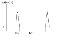
- the high-pressure air generation unit 5 described with reference to FIG. 4 may operate as follows. Specifically, in FIG. 18, the piston 52 in the high-pressure air generating unit 5 is moved from the top dead center (the state where the end 52 ⁇ / b> A is positioned on the imaginary line L of the first space 60 a) to the bottom dead center (shown in FIG. 4). The time during which the piston 52 moves from the bottom dead center to the top dead center is defined as the exhaust time (delivery time) t1. At this time, as shown in FIG. 18, the accumulation time t2 is preferably 10 times or more of the delivery time t1.
- the piston 52 is slowly moved from the top dead center to the bottom dead center, while the movement from the bottom dead center to the top dead center is instantaneously performed, that is, sufficiently longer than the delivery time t1.
- instantaneously exhausting the air within the delivery time t1 while ensuring the reservoir time t2 even in the high-pressure air generating unit 5 where the biasing force of the biasing spring 58 is small, water droplets attached to the lens 101 are reliably moved. be able to.
- the speed of the piston 52 in the sending direction which is the moving direction for sending out air
- the speed in the direction of the retentive force which is the moving direction when inhaling air.
- the moving speed of the air in the communication passage 71 is also faster during exhaust than during intake.
- FIG. 19 is a perspective view of a foreign matter removing apparatus according to the third embodiment of the present invention.
- the foreign matter removing apparatus 1000 includes a nozzle unit 1002, a joint member 3, a hose 4, and a high-pressure air generation unit (an example of a generation unit) 5. Since the basic configuration of the nozzle unit 1002 is the same as that of the nozzle unit 2 of the first embodiment, repeated description is omitted. In addition, parts having the same numbers as those described above have the same functions and operations, and thus repetitive description is omitted.
- the mounting portion 1021 of the nozzle unit 1002 has a substantially rectangular top plate 1021A and two side plates 1021B and 1021C.
- the side plate 1021B is provided so as to protrude from the lower surface side of the top plate 1021A continuously to one end of the top plate 1021A.
- the side plate 1021C is located on the opposite side to the side plate 1021B, and is provided so as to protrude from the lower surface side of the top plate 1021A continuously to the other end of the top plate 1021A.
- a material having excellent elasticity is used for the resin constituting the mounting portion 1021.
- the nozzle 1022 of the nozzle unit 1002 is arranged at the center of the mounting portion 1021 on the top plate 1021A.
- the nozzle 1022 has a connecting portion 1022A and a top wall 1022B (an example of a first wall portion).
- the connecting portion 1022A is a portion to which the joint member 3 is connected.
- the connecting portion 1022A is provided with an inflow port 1023 into which high-pressure air flows.
- the ceiling wall 1022B is a portion from which high-pressure air is ejected, and protrudes obliquely downward from the upper portion of the connecting portion 1022A.
- the high-pressure air flowing into the inflow port 1023 is ejected toward the lens 101 along the top wall 1022B through the connecting portion 1022A.
- the housing 102 of the in-vehicle camera 100 is formed in a cubic shape, for example.
- the housing 102 has an upper surface (an example of a first surface) 102A, side surfaces 102B and 102C continuous with both ends of the upper surface 102A, and a front surface (front surface of the camera) continuous with one end of each of the upper surface 102A, right side surface 102B, and left side surface 102C.
- Example) 102H The front surface 102H is a planar view region when the housing 102 is viewed from the front as a single unit.
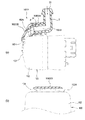
- the top wall 1022B of the nozzle 1022 is disposed at a position facing the front surface 102H of the housing 102 in a state where the mounting portion 1021 of the nozzle unit 1002 is mounted on the housing 102 of the in-vehicle camera 100.
- the injection port of the nozzle 1022 is formed only from the top wall 1022B, and a wall (bottom wall) facing the top wall 1022B and side walls extending from both ends of the top wall 1022B are not formed.
- the nozzle 1022 is disposed toward the lens 101 so that the top wall 1022B is along the shoulder between the upper surface 102A and the upper surface 102A and the front surface 102H of the housing 102, and the tip of the top wall 1022B is The lens 101 is positioned so as to face the lens 101.
- the high-pressure air that has flowed into the inflow port 1023 of the connecting portion 1022A passes between the top wall 1022B and the upper surface 102A of the housing 102, and is ejected from between the top wall 1022B and the front surface 102H of the housing 102.
- a high-pressure air outlet is formed between the top wall 1022B and the housing 102.
- the shape of the nozzle 1022 is configured so that the high-pressure air flowing into the nozzle 1022 from the high-pressure air generation unit 5 is jetted toward the lens 101 while being applied to the top wall 1022B.
- the nozzle 1022 is formed so that the angle ⁇ formed by the connecting portion 1022A and the top wall 1022B is an obtuse angle, preferably 110 ° or more and 160 ° or less.
- the top wall 1022B has a shape that extends substantially parallel to the front surface 102H of the housing 102 of the in-vehicle camera 100 in a top view with the nozzle unit 1002 attached to the in-vehicle camera 100. No side wall or the like extending from the top wall 1022B to the front surface 102H side of the housing 102 is provided.
- the high-pressure air flows into the inlet 1023 (see FIG. 23A) of the nozzle 1022, and flows between the top wall 1022B and the front surface 102H of the housing 102.
- the high-pressure air that has flowed in between the top wall 1022 ⁇ / b> B and the front surface 102 ⁇ / b> H of the housing 102 flows along the shoulder of the front surface 102 ⁇ / b> H of the housing 102 and is blown toward the lens 101 of the in-vehicle camera 100. Thereby, the foreign matter adhering to the lens 101 is blown away, and the dirt of the lens 101 is eliminated.
- the nozzle outlet is arranged at a position facing the upper surface of the camera housing as in the conventional foreign matter removing apparatus, it is difficult to efficiently blow high-pressure air onto the lens. Further, if the nozzle tip is formed with a wall that covers the entire peripheral surface of the high-pressure air outlet, it is necessary to make the space for attaching the foreign substance removing device relatively large.
- the tip of the nozzle 1022 is formed from the top wall 1022B facing the front surface 102H of the camera 100. For this reason, since the high-pressure air sent from the high-pressure air generation unit 5 flows between the top wall 1022B and the front surface 102H of the camera housing 102 and is efficiently blown onto the lens 101, the performance of removing foreign matters can be maintained. it can. Further, the tip of the nozzle 1022 is formed only from the top wall 1022B, and the nozzle ejection portion is not formed by the wall portion covering the entire peripheral surface of the high-pressure air ejection port as in the prior art. It is simple and can reduce the thickness of the jet outlet of the nozzle 1022 to save space, and is very excellent in mounting on a vehicle.
- the shape of the nozzle 1022 is configured so that the high-pressure air flowing into the nozzle 1022 from the high-pressure air generating unit 5 is jetted toward the lens 101 while being applied to the top wall 1022B.
- high-pressure air can be rectified, and high-pressure air with an appropriate air volume can be sent to an appropriate location on the surface of the lens 101.
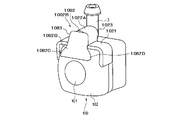
- FIG. 24 shows a nozzle unit 1002A attached to the in-vehicle camera 100.
- FIG. 25 (a) is a side view of the state in which the nozzle unit 1002A is attached to the in-vehicle camera 100
- FIG. 25 (b) is a longitudinal sectional view taken along the line HH in FIG. c) shows a cross-sectional view taken along the line II in FIG.
- the nozzle 1072 of the modified example 4 is different in the structure of the ejection part 1073 compared to the nozzle 1022 (see FIGS. 21, 22 and the like).
- the repeated description is abbreviate
- the nozzle unit 1002A has a mounting portion 1021 and a nozzle 1072.
- the nozzle 1072 has a connecting portion 1022A and an ejection portion 1073.
- the ejection part 1073 is a part from which high-pressure air is ejected, and the high-pressure air that has flowed into the inlet 1023 via the joint member 3 is ejected from the ejection part 1073 through the connecting part 1022A.
- the ejection portion 1073 has a top wall 1072B facing the front surface 102H of the housing 102, and two side walls 1072C and 1072D (an example of a second wall portion).
- the side wall 1072C is provided so as to continuously extend from one end of the top wall 1072B in a direction away from the top wall 1072B.
- the side wall 1072D is located on the opposite side of the side wall 1072C, and is provided so as to continuously extend from the other end of the top wall 1072B in a direction away from the top wall 1072B.
- the ejection part 1073 of the nozzle 1072 is constituted by the top wall 1072B and the side walls 1072C and 1072D, and a wall (bottom wall) facing the top wall 1072B is not formed.
- the nozzle 1072 is configured such that the side walls 1072C and 1072D of the ejection portion 1073 are in contact with the front surface 102H of the housing 102 in a state where the attachment portion 1021 is attached to the housing 102 of the in-vehicle camera 100 (FIG. 25C). reference).
- the side walls 1072C and 1072D come into contact with the front surface 102H, the position of the nozzle 1072 with respect to the front surface 102H of the housing 102 is determined.
- the ejection portion 1073 is formed with a communication passage 1074 surrounded by the top wall 1072B, the side walls 1072C and 1072D, and the front surface 102H of the housing 102 (FIG. 25 ( b) and (c)). High-pressure air is ejected from the ejection port 1075 through the communication path 1074.
- the top wall 1072B, the side walls 1072C and 1072D, and the front surface 102H of the camera housing 102 form the communication path 1074 that covers the entire peripheral surface of the high-pressure air blowing port, so that the high pressure blown from the nozzle 1072 is formed. Air can be guided to the lens 101 more efficiently.
- it is fixed to the housing 102 of the in-vehicle camera 100 by the mounting portion 1021 and positioned by contacting the side walls 1072C and 1072D of the nozzle 1072 with the front surface 102H of the housing 102.
- the tip of the nozzle 1072 can be accurately positioned with respect to the lens 101 of the in-vehicle camera 100 not only in the left-right direction but also in the front-rear direction of the in-vehicle camera 100. Further, since the ejection portion 1073 is constituted by the top wall 1072B and the side walls 1072C and 1072D and does not have a bottom wall facing the top wall 1072B, the thickness of the nozzle 1072 can be reduced and space saving can be achieved. Can also be achieved.
- the side walls 1072C and 1072D are configured to contact the front surface 102H of the housing 102, but the side walls 1072C and 1072D may not be configured to contact the front surface 102H. Even in this case, the high-pressure air can be efficiently guided toward the lens 101 by the top wall and the side wall. Further, as shown in FIG. 26, the top wall 1074B may be formed to have a circular arc shape in accordance with the circular arc shape of the lens 101. Thereby, high-pressure air can be uniformly guided to the entire surface of the lens 101.
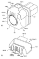
- the nozzle unit 1002B has a mounting portion 1021 and a nozzle 1082.
- the nozzle 1082 has a connecting portion 1022A and an ejection portion 1083.
- the ejection part 1083 has a top wall 1082B that faces the front surface 102H of the housing 102, and side walls 1082C and 1082D that extend from both ends of the top wall 1082B toward the lens 101 side.
- the top wall 1082B is formed in a shape that is enlarged in a fan shape from the connecting portion 1022A toward the front surface of the lower lens 101.
- the high-pressure air that has flowed into the inflow port 1023 through the joint member 3 is ejected from the ejection part 1083 through the connecting part 1022A.
- the top wall 1082B is formed in a fan shape, high-pressure air can be blown substantially uniformly toward the entire outer surface of the lens 101.
- the nozzle unit 1002C has a mounting portion 1021 and a nozzle 1092.
- the nozzle 1092 has an opening 1092A and an ejection part 1093.
- the opening portion 1092A is an opening through which a high-pressure air is introduced by inserting a hose or a joint member (not shown) that is connected to the high-pressure air generation unit 5 and sends out the high-pressure air therein.
- the ejection portion 1093 is a portion from which high-pressure air is ejected, and the high-pressure air that has flowed from the opening 1092A is ejected from the ejection port 1094 of the ejection portion 1093.
- the ejection part 1093 has a top wall 1092B facing the front surface 102H of the housing 102, and two side walls 1092C and 1092D.
- a plurality of elongated protrusions 1095 are provided in the top wall 1092B in the top wall 1092B, a plurality of elongated protrusions 1095 are provided on a surface 1092B1 (see FIG. 28B) facing the front surface 102H of the housing 102.
- the protrusion 1095 is a member for rectifying high-pressure air and blowing it to the lens 101.
- the arrangement pitch between the protrusions 1095A at the center is slightly narrower than the arrangement pitch between the protrusions 1095B on both sides and the protrusions 1095A on the inside.
- the nozzle 1092 is arranged so that the side walls 1092C and 1092D of the ejection portion 1093 are in contact with the front surface 102H of the housing 102 in a state where the attachment portion 1021 is attached to the housing 102 of the in-vehicle camera 100, and the top wall 1092B A communication path surrounded by the side walls 1092C and 1092D and the front surface 102H of the housing 102 is formed.
- the high-pressure air that has flowed in through the opening 1092A is jetted from the jet outlet 1094 toward the lens 101 while being rectified by the protrusion 1095 formed in the communication path.
- the high pressure air is more efficiently blown to the lens 101 by controlling the injection direction, the amount, the pressure, and the like of the high pressure air at the ejection portion 1093 by the protrusion 1095. Can do.
- the foreign matter removing apparatus 1,1000 in which high pressure air is generated by the high pressure air generating unit 5 and high pressure air is ejected from the nozzle 22 to remove foreign matter on the lens.
- the nozzle unit according to the embodiment and the modified example as a foreign matter removing device including a storage unit that stores the cleaning liquid and a nozzle that sprays the cleaning liquid toward the lens of the camera.
- the joint member 3 is provided as a member for joining the nozzle 22 and the hose 4 of the nozzle unit 2, but there is no need to change the posture of the hose 4 with respect to the nozzle 22.
- the hose 4 may be directly attached to the nozzle 22 without providing the joint member 3.
- this invention is not limited to embodiment mentioned above, A deformation
- the material, shape, dimension, numerical value, form, number, location, and the like of each component in the above-described embodiment are arbitrary and are not limited as long as the present invention can be achieved.
- the application to the vehicle-mounted camera is described, but the target to which the present invention is applied is not limited as long as it is a camera used outdoors.
- the target to which the present invention is applied is not limited as long as it is a camera used outdoors.
- it includes a camera attached so as to be exposed to the outside such as an aircraft, a railway, a ship, a robot, an outdoor installation, a building, and the like.
- the present invention is applicable to sensors that can be attached to a vehicle, such as LIDAE (laser radar), millimeter wave radar, and ultrasonic sensor.
- LIDAE laser radar
- millimeter wave radar millimeter wave radar
- ultrasonic sensor ultrasonic sensor
- the target part from which the foreign substance removing device removes the foreign substance is not limited to the camera lens.
- an optical lens of a sensor element a cover that covers the front surface of the optical lens, a lamp that has a part that functions as a communication window for the sensor, a cover for vehicle cover parts such as a mirror, a bumper, a grille, and a doorknob, and a sensor mounted in the vehicle compartment
- the present invention can be applied to a foreign matter removing apparatus that removes foreign matter adhering to a “partition wall” defined as a concept encompassing a vehicle window and the like in such a case.
- This partition is not limited to a transparent member (translucent), and may not be transparent in an ultrasonic sensor, a millimeter wave radar, or the like.
Landscapes
- Engineering & Computer Science (AREA)
- Mechanical Engineering (AREA)
- Multimedia (AREA)
- Signal Processing (AREA)
- Studio Devices (AREA)
- Nozzles (AREA)
Abstract
L'invention concerne un dispositif d'élimination de substance étrangère qui élimine une substance étrangère se trouvant sur une lentille (101) d'une caméra embarquée (100) installée sur un véhicule, de sorte que la lentille (101) de la caméra embarquée (100) est dans un état d'exposition vers le côté externe d'un panneau de corps du véhicule. Ce dispositif d'élimination de substance étrangère est équipé : d'une partie production (5) produisant un air haute pression ; et d'une unité buse qui possède une buse (22) pulvérisant cet air haute pression vers la lentille (101), et une partie installation (21) formée d'un seul tenant avec la buse (22), et permettant son installation sur un logement (102) de la caméra embarquée (100). Dans un état d'installation de la partie installation (21) sur le logement (102) de la caméra embarquée (100), une extrémité avant de la buse (22) est positionnée par rapport à la lentille (101).
Priority Applications (6)
| Application Number | Priority Date | Filing Date | Title |
|---|---|---|---|
| US15/740,871 US10604122B2 (en) | 2015-06-30 | 2016-06-29 | Foreign matter removal device and vehicle provided with same |
| EP16817986.9A EP3318454B1 (fr) | 2015-06-30 | 2016-06-29 | Dispositif d'élimination de substance étrangère, et véhicule équipé de celui-ci |
| CN201680038321.8A CN107709106B (zh) | 2015-06-30 | 2016-06-29 | 异物去除装置及具备该异物去除装置的车辆 |
| CN202310960274.4A CN116946071A (zh) | 2015-06-30 | 2016-06-29 | 异物去除装置 |
| JP2017526412A JP6641370B2 (ja) | 2015-06-30 | 2016-06-29 | 異物除去装置および当該異物除去装置を備える車両 |
| US16/807,432 US20200198591A1 (en) | 2015-06-30 | 2020-03-03 | Foreign matter removal device and vehicle provided with same |
Applications Claiming Priority (6)
| Application Number | Priority Date | Filing Date | Title |
|---|---|---|---|
| JP2015-131788 | 2015-06-30 | ||
| JP2015-131785 | 2015-06-30 | ||
| JP2015131788 | 2015-06-30 | ||
| JP2015131786 | 2015-06-30 | ||
| JP2015131785 | 2015-06-30 | ||
| JP2015-131786 | 2015-06-30 |
Related Child Applications (2)
| Application Number | Title | Priority Date | Filing Date |
|---|---|---|---|
| US15/740,871 A-371-Of-International US10604122B2 (en) | 2015-06-30 | 2016-06-29 | Foreign matter removal device and vehicle provided with same |
| US16/807,432 Continuation US20200198591A1 (en) | 2015-06-30 | 2020-03-03 | Foreign matter removal device and vehicle provided with same |
Publications (1)
| Publication Number | Publication Date |
|---|---|
| WO2017002878A1 true WO2017002878A1 (fr) | 2017-01-05 |
Family
ID=57608351
Family Applications (1)
| Application Number | Title | Priority Date | Filing Date |
|---|---|---|---|
| PCT/JP2016/069335 Ceased WO2017002878A1 (fr) | 2015-06-30 | 2016-06-29 | Dispositif d'élimination de substance étrangère, et véhicule équipé de celui-ci |
Country Status (5)
| Country | Link |
|---|---|
| US (2) | US10604122B2 (fr) |
| EP (1) | EP3318454B1 (fr) |
| JP (3) | JP6641370B2 (fr) |
| CN (2) | CN116946071A (fr) |
| WO (1) | WO2017002878A1 (fr) |
Cited By (19)
| Publication number | Priority date | Publication date | Assignee | Title |
|---|---|---|---|---|
| CN108525871A (zh) * | 2017-03-02 | 2018-09-14 | 株式会社本田阿克塞斯 | 喷射用喷嘴构件 |
| WO2019044113A1 (fr) * | 2017-08-30 | 2019-03-07 | 株式会社小糸製作所 | Unité de nettoyage de véhicule et véhicule pourvu de l'unité de nettoyage de véhicule |
| WO2019044399A1 (fr) * | 2017-08-30 | 2019-03-07 | 株式会社小糸製作所 | Filtre à air pour véhicule |
| EP3470278A1 (fr) * | 2017-10-12 | 2019-04-17 | Toyota Jidosha Kabushiki Kaisha | Véhicule |
| WO2019106930A1 (fr) * | 2017-11-28 | 2019-06-06 | 株式会社デンソー | Dispositif de nettoyage de capteur embarqué |
| US10328906B2 (en) | 2014-04-11 | 2019-06-25 | Dlhbowles, Inc. | Integrated automotive system, compact, low-profile nozzle assembly and compact fluidic circuit for cleaning a wide-angle image sensor's exterior surface |
| US10350647B2 (en) | 2011-03-10 | 2019-07-16 | Dlhbowles, Inc. | Integrated automotive system, nozzle assembly and remote control method for cleaning an image sensor's exterior or objective lens surface |
| US10432827B2 (en) | 2011-03-10 | 2019-10-01 | Dlhbowles, Inc. | Integrated automotive system, nozzle assembly and remote control method for cleaning an image sensors exterior or objective lens surface |
| US10525937B2 (en) | 2014-04-16 | 2020-01-07 | Dlhbowles, Inc. | Integrated multi image sensor and lens washing nozzle assembly and method for simultaneously cleaning a plurality of image sensors |
| CN110662003A (zh) * | 2019-10-28 | 2020-01-07 | 南京茗淇信息科技有限公司 | 一种基于5g网络的具有清洁功能的视频监控装置 |
| CN111032451A (zh) * | 2017-08-30 | 2020-04-17 | 株式会社小糸制作所 | 车牌板灯单元以及具备车牌板灯单元的车辆 |
| WO2020158938A1 (fr) * | 2019-02-01 | 2020-08-06 | 株式会社小糸製作所 | Dispositif de nettoyage pour véhicules, support pour véhicules, et unité de nettoyage pour véhicules |
| JP2021120142A (ja) * | 2020-01-30 | 2021-08-19 | 株式会社デンソーテン | ノズル装置 |
| US11693095B2 (en) | 2018-11-20 | 2023-07-04 | Toyota Jidosha Kabushiki Kaisha | Sensor mounting structure |
| JP2023547957A (ja) * | 2020-10-28 | 2023-11-14 | ウルソップ シム | 光学装置のカバーを洗浄するための洗浄装置 |
| US20240190391A1 (en) * | 2022-12-13 | 2024-06-13 | Hyundai Motor Company | Cleaning apparatus |
| DE112017004676B4 (de) * | 2016-09-16 | 2024-08-14 | Methode Electronics, Inc. | Kameraobjektiv-/Sensorreinigungsvorrichtung |
| US12285769B2 (en) | 2021-07-06 | 2025-04-29 | Abc Technologies Inc. | Pulsating spray cleaning nozzle assembly and method |
| DE102019203547B4 (de) * | 2018-03-15 | 2025-07-10 | Koito Manufacturing Co., Ltd. | Fahrzeugsystem |
Families Citing this family (29)
| Publication number | Priority date | Publication date | Assignee | Title |
|---|---|---|---|---|
| FR3062764B1 (fr) * | 2017-02-08 | 2019-08-02 | Valeo Systemes D'essuyage | Dispositif de vision, systeme d’assistance a la conduite et procede de maintien de la visibilite associes |
| DE102017127526B4 (de) * | 2017-11-22 | 2023-10-12 | Rheinmetall Landsysteme Gmbh | Blende und Vorrichtung zur Reinigung von Sichtsystemen |
| JP6900332B2 (ja) * | 2018-02-01 | 2021-07-07 | 株式会社ミツバ | ウォッシャノズル |
| US10549723B2 (en) * | 2018-05-04 | 2020-02-04 | Ford Global Technologies, Llc | Vehicle object-detection sensor assembly |
| CN109089022B (zh) * | 2018-07-25 | 2021-01-22 | 林春芬 | 一种用于下雨天前后的具有气流驱蚁的交通道路监管设备 |
| WO2020137823A1 (fr) * | 2018-12-26 | 2020-07-02 | 株式会社小糸製作所 | Unité de nettoyage de véhicule et système de nettoyage de véhicule |
| CN111656272B (zh) * | 2019-01-04 | 2024-04-16 | 京东方科技集团股份有限公司 | 液晶显示面板和显示装置 |
| US12141949B2 (en) * | 2019-03-26 | 2024-11-12 | Sony Semiconductor Solutions Corporation | Vehicle-mounted camera apparatus and image distortion correction method |
| DE202019106142U1 (de) * | 2019-11-05 | 2019-12-02 | Dallmeier Electronic Gmbh & Co. Kg | System zur Reinigung der Frontscheibe eines Kameragehäuses zumindest einer Überwachungskameraeinheit |
| CN110935690B (zh) * | 2019-11-28 | 2021-12-07 | 维沃移动通信有限公司 | 电子设备 |
| FR3104039B1 (fr) | 2019-12-10 | 2022-04-15 | Valeo Systemes Dessuyage | système de nettoyage d'un capteur/émetteur d'un véhicule automobile |
| CN113543899A (zh) * | 2020-02-11 | 2021-10-22 | 深圳元戎启行科技有限公司 | 无人驾驶传感器集成装置及无人驾驶系统 |
| KR102867475B1 (ko) * | 2020-04-01 | 2025-10-14 | 한국전자기술연구원 | 차량탑재 광학기기의 렌즈보호를 위한 에어하우징 장치 |
| EP4173901A4 (fr) * | 2020-06-30 | 2024-04-03 | Koito Manufacturing Co., Ltd. | Buse, ensemble buse et appareil de nettoyage |
| KR102789185B1 (ko) * | 2020-08-25 | 2025-04-01 | 현대모비스 주식회사 | 차량 모니터링 장치 |
| US20220135005A1 (en) * | 2020-10-29 | 2022-05-05 | Argo AI, LLC | Method and system for diverting ram air to vehicle sensors |
| EP4245611A4 (fr) * | 2020-11-10 | 2024-08-28 | Agc Inc. | Élément en résine pour véhicule, élément de fenêtre de véhicule et véhicule |
| DE102021210086A1 (de) * | 2021-09-13 | 2023-03-16 | Continental Automotive Technologies GmbH | Pneumatische Vorrichtung für eine Sensorvorrichtung eines Fahrzeugs |
| JP7791680B2 (ja) * | 2021-10-06 | 2025-12-24 | 株式会社デンソーテン | 流体噴射ノズル |
| CN113877889B (zh) * | 2021-11-03 | 2022-12-23 | 杭州海康威视数字技术股份有限公司 | 一种摄像机 |
| CN114289411B (zh) * | 2021-12-17 | 2023-02-28 | 杭州海康汽车软件有限公司 | 摄像机组件 |
| EP4265486A1 (fr) * | 2022-04-20 | 2023-10-25 | Valeo Systèmes d'Essuyage | Dispositif de nettoyage pour système de détection d'un véhicule à moteur |
| DE102022209212A1 (de) * | 2022-09-05 | 2024-03-07 | Continental Automotive Technologies GmbH | Vorrichtung zum Beaufschlagen einer Sensoroberfläche mit Luftströmung |
| DE102022209211A1 (de) * | 2022-09-05 | 2024-03-07 | Continental Automotive Technologies GmbH | Vorrichtung zum Beaufschlagen einer Sensoroberfläche mit Luftströmung |
| DE102022209213A1 (de) * | 2022-09-05 | 2024-03-07 | Continental Automotive Technologies GmbH | 7Vorrichtung zum Beaufschlagen einer Sensoroberfläche mit Luftströmung |
| EP4626008A1 (fr) * | 2022-11-24 | 2025-10-01 | Koito Manufacturing Co., Ltd. | Dispositif de nettoyage et ensemble capteur |
| US20250136059A1 (en) * | 2023-10-25 | 2025-05-01 | Andrew Lavanture | On-vehicle camera cleaning device and method of use |
| WO2025192651A1 (fr) * | 2024-03-13 | 2025-09-18 | 株式会社小糸製作所 | Dispositif de nettoyage et ensemble capteur |
| WO2025192649A1 (fr) * | 2024-03-13 | 2025-09-18 | 株式会社小糸製作所 | Kit d'assemblage de dispositif de nettoyage et procédé d'assemblage de dispositif de nettoyage |
Citations (13)
| Publication number | Priority date | Publication date | Assignee | Title |
|---|---|---|---|---|
| JP2001171491A (ja) | 1999-12-16 | 2001-06-26 | Matsushita Electric Ind Co Ltd | 車載カメラ装置及び車載カメラの洗浄方法 |
| JP2009083730A (ja) * | 2007-10-01 | 2009-04-23 | Panasonic Corp | 車載カメラ |
| JP2012035654A (ja) * | 2010-08-03 | 2012-02-23 | Asmo Co Ltd | 車載カメラ用ノズル装置、清掃装置付き車載カメラ、及び車載カメラ用清掃システム |
| WO2014010579A1 (fr) * | 2012-07-11 | 2014-01-16 | 日産自動車株式会社 | Dispositif de nettoyage de caméra embarquée |
| JP2014069586A (ja) | 2012-09-27 | 2014-04-21 | Asmo Co Ltd | 車載カメラ用ウォッシャノズル |
| JP2015083830A (ja) * | 2013-09-19 | 2015-04-30 | アスモ株式会社 | 電動ポンプ、及び車載光学センサ洗浄装置 |
| US20150185592A1 (en) * | 2012-07-02 | 2015-07-02 | Agricam Ab | Camera housings, camera modules, and monitoring systems |
| JP2015131785A (ja) | 2014-01-15 | 2015-07-23 | Agcセイミケミカル株式会社 | 誘電率異方性が負の環構造を有する新規な化合物およびその製造方法、液晶組成物および液晶電気光学素子 |
| JP2015131786A (ja) | 2014-01-16 | 2015-07-23 | 田岡化学工業株式会社 | 9,9’−スピロビフルオレン類の製造方法 |
| JP2015131788A (ja) | 2014-01-14 | 2015-07-23 | 有限会社湘南予防医科学研究所 | 育毛・発毛促進剤 |
| WO2015159763A1 (fr) * | 2014-04-14 | 2015-10-22 | 株式会社小糸製作所 | Dispositif de retrait de matière étrangère |
| US20150353024A1 (en) * | 2014-06-06 | 2015-12-10 | Joseph Richard Cooper | Obstruction-removal system and method for vehicle-camera lens |
| JP2015224032A (ja) * | 2014-05-27 | 2015-12-14 | フィコ トランスパー,ソシエダ アノニマ | 車載光学レンズの洗浄システムおよび洗浄方法 |
Family Cites Families (32)
| Publication number | Priority date | Publication date | Assignee | Title |
|---|---|---|---|---|
| JPH041708U (fr) | 1990-04-20 | 1992-01-08 | ||
| JPH0519615U (ja) | 1991-08-29 | 1993-03-12 | シヤープ株式会社 | 銘板取付装置 |
| JP3063922U (ja) | 1999-05-14 | 1999-12-10 | 有限会社大東製作所 | 銃玩具の空気ポンプ作動装置 |
| JP2002240628A (ja) | 2001-02-19 | 2002-08-28 | Viewtec Japan Co Ltd | 自動車用バックアイカメラ |
| JPWO2005066575A1 (ja) | 2003-12-26 | 2007-07-26 | 宏一 鶴本 | エアガンおよびその発射回数切替制御方法 |
| JP2007053448A (ja) | 2005-08-15 | 2007-03-01 | Fujifilm Corp | 撮影装置 |
| US20080078429A1 (en) * | 2006-09-28 | 2008-04-03 | Hoffmann Terry A | Cleaning device for paint rollers |
| EP2113736B8 (fr) | 2007-02-16 | 2020-03-04 | TOKYO MARUI Co., Ltd. | Dispositif de choc de recul dans une arme-jouet |
| JP4513889B2 (ja) | 2008-04-03 | 2010-07-28 | 株式会社日本自動車部品総合研究所 | ウォッシャノズル付カメラおよびウォッシャノズル |
| JP5407682B2 (ja) | 2009-09-10 | 2014-02-05 | トヨタ自動車株式会社 | 車体外装部品の取付シール構造 |
| JP5056919B2 (ja) * | 2009-09-29 | 2012-10-24 | 株式会社デンソー | 車載光学センサカバー及び車載光学センサ装置 |
| US20110292212A1 (en) * | 2010-05-27 | 2011-12-01 | Asmo Co., Ltd. | Washer nozzle for vehicle mounted camera, vehicle mounted camera, and washer device for vehicle |
| JP2011245989A (ja) | 2010-05-27 | 2011-12-08 | Asmo Co Ltd | 車載カメラ用ウォッシャノズル、車載カメラ、及び車両用ウォッシャ装置 |
| JP2012201122A (ja) | 2011-03-23 | 2012-10-22 | Asmo Co Ltd | 車載カメラ用ノズル装置、清掃装置付き車載カメラ、及び車載カメラ用清掃システム |
| JP5643157B2 (ja) | 2011-06-23 | 2014-12-17 | アスモ株式会社 | 車載カメラ用ウォッシャノズル及び車載カメラ洗浄システム |
| US8931467B2 (en) | 2011-07-05 | 2015-01-13 | Si Young Lee | Magazine rifle |
| JP2013018404A (ja) | 2011-07-12 | 2013-01-31 | Asmo Co Ltd | 車載カメラ用ウォッシャノズル |
| US20130086766A1 (en) * | 2011-10-07 | 2013-04-11 | Derrick André Allen | Attachable windshield wiper system for a helmet |
| JP5494743B2 (ja) | 2011-10-14 | 2014-05-21 | 株式会社デンソー | カメラ洗浄装置 |
| JP2013154771A (ja) * | 2012-01-30 | 2013-08-15 | Asmo Co Ltd | 車載カメラ装置 |
| CN103313565B (zh) * | 2012-03-06 | 2016-08-31 | 宏碁股份有限公司 | 卡合机构 |
| JP6090319B2 (ja) | 2012-07-11 | 2017-03-08 | 日産自動車株式会社 | 車載カメラの洗浄装置 |
| CN104470770B (zh) | 2012-07-11 | 2016-06-15 | 日产自动车株式会社 | 车载摄像机的清洗装置 |
| BR112015000243B1 (pt) | 2012-07-11 | 2021-07-13 | Nissan Motor Co., Ltd | Dispositivo de limpeza para câmera montada em veículo e método de limpar câmera montada em veículo |
| CN202779193U (zh) | 2012-07-16 | 2013-03-13 | 宝山钢铁股份有限公司 | 一种热轧旋转式侧喷气吹扫装置 |
| JP5850157B2 (ja) * | 2012-07-27 | 2016-02-03 | 日産自動車株式会社 | 車載カメラ装置 |
| CN103056054B (zh) * | 2013-01-29 | 2015-07-22 | 厦门建霖工业有限公司 | 多功能分配器 |
| US9126534B2 (en) * | 2013-03-14 | 2015-09-08 | Ford Global Technologies, Llc | Automated camera wash for vehicles |
| JP6379665B2 (ja) * | 2013-08-12 | 2018-08-29 | 株式会社デンソー | 車載光学センサ洗浄装置 |
| CN204240007U (zh) * | 2014-10-30 | 2015-04-01 | 许诏智 | 卡扣固定装置 |
| JP6654145B2 (ja) | 2014-12-22 | 2020-02-26 | 株式会社小糸製作所 | 異物除去装置、除去駆動装置 |
| US20160272163A1 (en) * | 2015-03-17 | 2016-09-22 | Magna Electronics Inc. | Vehicle camera with lens washer system |
-
2016
- 2016-06-29 EP EP16817986.9A patent/EP3318454B1/fr active Active
- 2016-06-29 CN CN202310960274.4A patent/CN116946071A/zh active Pending
- 2016-06-29 CN CN201680038321.8A patent/CN107709106B/zh active Active
- 2016-06-29 JP JP2017526412A patent/JP6641370B2/ja active Active
- 2016-06-29 US US15/740,871 patent/US10604122B2/en active Active
- 2016-06-29 WO PCT/JP2016/069335 patent/WO2017002878A1/fr not_active Ceased
-
2018
- 2018-02-13 JP JP2018023055A patent/JP6370507B2/ja active Active
- 2018-02-13 JP JP2018023056A patent/JP6434663B2/ja active Active
-
2020
- 2020-03-03 US US16/807,432 patent/US20200198591A1/en not_active Abandoned
Patent Citations (13)
| Publication number | Priority date | Publication date | Assignee | Title |
|---|---|---|---|---|
| JP2001171491A (ja) | 1999-12-16 | 2001-06-26 | Matsushita Electric Ind Co Ltd | 車載カメラ装置及び車載カメラの洗浄方法 |
| JP2009083730A (ja) * | 2007-10-01 | 2009-04-23 | Panasonic Corp | 車載カメラ |
| JP2012035654A (ja) * | 2010-08-03 | 2012-02-23 | Asmo Co Ltd | 車載カメラ用ノズル装置、清掃装置付き車載カメラ、及び車載カメラ用清掃システム |
| US20150185592A1 (en) * | 2012-07-02 | 2015-07-02 | Agricam Ab | Camera housings, camera modules, and monitoring systems |
| WO2014010579A1 (fr) * | 2012-07-11 | 2014-01-16 | 日産自動車株式会社 | Dispositif de nettoyage de caméra embarquée |
| JP2014069586A (ja) | 2012-09-27 | 2014-04-21 | Asmo Co Ltd | 車載カメラ用ウォッシャノズル |
| JP2015083830A (ja) * | 2013-09-19 | 2015-04-30 | アスモ株式会社 | 電動ポンプ、及び車載光学センサ洗浄装置 |
| JP2015131788A (ja) | 2014-01-14 | 2015-07-23 | 有限会社湘南予防医科学研究所 | 育毛・発毛促進剤 |
| JP2015131785A (ja) | 2014-01-15 | 2015-07-23 | Agcセイミケミカル株式会社 | 誘電率異方性が負の環構造を有する新規な化合物およびその製造方法、液晶組成物および液晶電気光学素子 |
| JP2015131786A (ja) | 2014-01-16 | 2015-07-23 | 田岡化学工業株式会社 | 9,9’−スピロビフルオレン類の製造方法 |
| WO2015159763A1 (fr) * | 2014-04-14 | 2015-10-22 | 株式会社小糸製作所 | Dispositif de retrait de matière étrangère |
| JP2015224032A (ja) * | 2014-05-27 | 2015-12-14 | フィコ トランスパー,ソシエダ アノニマ | 車載光学レンズの洗浄システムおよび洗浄方法 |
| US20150353024A1 (en) * | 2014-06-06 | 2015-12-10 | Joseph Richard Cooper | Obstruction-removal system and method for vehicle-camera lens |
Cited By (38)
| Publication number | Priority date | Publication date | Assignee | Title |
|---|---|---|---|---|
| US10350647B2 (en) | 2011-03-10 | 2019-07-16 | Dlhbowles, Inc. | Integrated automotive system, nozzle assembly and remote control method for cleaning an image sensor's exterior or objective lens surface |
| US10432827B2 (en) | 2011-03-10 | 2019-10-01 | Dlhbowles, Inc. | Integrated automotive system, nozzle assembly and remote control method for cleaning an image sensors exterior or objective lens surface |
| US10328906B2 (en) | 2014-04-11 | 2019-06-25 | Dlhbowles, Inc. | Integrated automotive system, compact, low-profile nozzle assembly and compact fluidic circuit for cleaning a wide-angle image sensor's exterior surface |
| US10525937B2 (en) | 2014-04-16 | 2020-01-07 | Dlhbowles, Inc. | Integrated multi image sensor and lens washing nozzle assembly and method for simultaneously cleaning a plurality of image sensors |
| US11472375B2 (en) | 2014-04-16 | 2022-10-18 | Dlhbowles, Inc. | Integrated multi image sensor and lens washing nozzle assembly and method for simultaneously cleaning a plurality of image sensors |
| DE112017004676B4 (de) * | 2016-09-16 | 2024-08-14 | Methode Electronics, Inc. | Kameraobjektiv-/Sensorreinigungsvorrichtung |
| JP2018144542A (ja) * | 2017-03-02 | 2018-09-20 | 株式会社ホンダアクセス | 噴射用ノズル部材 |
| DE102018203115B4 (de) | 2017-03-02 | 2025-10-02 | Honda Access Corp. | Ejektionsdüsenelement |
| CN108525871A (zh) * | 2017-03-02 | 2018-09-14 | 株式会社本田阿克塞斯 | 喷射用喷嘴构件 |
| JPWO2019044113A1 (ja) * | 2017-08-30 | 2020-08-20 | 株式会社小糸製作所 | 車両用クリーナユニットおよび車両用クリーナユニットを備える車両 |
| WO2019044399A1 (fr) * | 2017-08-30 | 2019-03-07 | 株式会社小糸製作所 | Filtre à air pour véhicule |
| CN111032452A (zh) * | 2017-08-30 | 2020-04-17 | 株式会社小糸制作所 | 车辆用清洁单元及具备车辆用清洁单元的车辆 |
| CN111032451A (zh) * | 2017-08-30 | 2020-04-17 | 株式会社小糸制作所 | 车牌板灯单元以及具备车牌板灯单元的车辆 |
| CN111051156A (zh) * | 2017-08-30 | 2020-04-21 | 株式会社小糸制作所 | 车辆用空气清洁器 |
| CN111032452B (zh) * | 2017-08-30 | 2024-03-08 | 株式会社小糸制作所 | 车辆用清洁单元及具备车辆用清洁单元的车辆 |
| JPWO2019044399A1 (ja) * | 2017-08-30 | 2020-08-13 | 株式会社小糸製作所 | 車両用エアクリーナ |
| CN111051156B (zh) * | 2017-08-30 | 2024-02-20 | 株式会社小糸制作所 | 车辆用空气清洁器 |
| EP3677478A4 (fr) * | 2017-08-30 | 2021-05-19 | Koito Manufacturing Co., Ltd. | Unité de lampe de plaque d'immatriculation et véhicule équipé d'une unité de lampe de plaque d'immatriculation |
| WO2019044113A1 (fr) * | 2017-08-30 | 2019-03-07 | 株式会社小糸製作所 | Unité de nettoyage de véhicule et véhicule pourvu de l'unité de nettoyage de véhicule |
| EP4015318A1 (fr) * | 2017-08-30 | 2022-06-22 | Koito Manufacturing Co., Ltd. | Dispositif de nettoyage à air pour véhicule |
| US11738720B2 (en) | 2017-08-30 | 2023-08-29 | Koito Manufacturing Co., Ltd. | Vehicle cleaner unit and vehicle provided with vehicle cleaner unit |
| US11535203B2 (en) | 2017-08-30 | 2022-12-27 | Koito Manufacturing Co.. Ltd. | Air cleaner for vehicles |
| US11535201B2 (en) | 2017-08-30 | 2022-12-27 | Koito Manufacturing Co., Ltd. | License plate lamp unit and vehicle provided with license plate lamp unit |
| JP7223696B2 (ja) | 2017-08-30 | 2023-02-16 | 株式会社小糸製作所 | 車両用エアクリーナ |
| JP7269880B2 (ja) | 2017-08-30 | 2023-05-09 | 株式会社小糸製作所 | 車両用クリーナユニットおよび車両用クリーナユニットを備える車両 |
| EP3470278A1 (fr) * | 2017-10-12 | 2019-04-17 | Toyota Jidosha Kabushiki Kaisha | Véhicule |
| WO2019106930A1 (fr) * | 2017-11-28 | 2019-06-06 | 株式会社デンソー | Dispositif de nettoyage de capteur embarqué |
| DE102019203547B4 (de) * | 2018-03-15 | 2025-07-10 | Koito Manufacturing Co., Ltd. | Fahrzeugsystem |
| US11693095B2 (en) | 2018-11-20 | 2023-07-04 | Toyota Jidosha Kabushiki Kaisha | Sensor mounting structure |
| WO2020158938A1 (fr) * | 2019-02-01 | 2020-08-06 | 株式会社小糸製作所 | Dispositif de nettoyage pour véhicules, support pour véhicules, et unité de nettoyage pour véhicules |
| US12157440B2 (en) | 2019-02-01 | 2024-12-03 | Koito Manufacturing Co., Ltd. | Cleaner for vehicles, bracket for cleaners for vehicles, and cleaner unit for vehicles |
| CN110662003A (zh) * | 2019-10-28 | 2020-01-07 | 南京茗淇信息科技有限公司 | 一种基于5g网络的具有清洁功能的视频监控装置 |
| JP2021120142A (ja) * | 2020-01-30 | 2021-08-19 | 株式会社デンソーテン | ノズル装置 |
| JP7401326B2 (ja) | 2020-01-30 | 2023-12-19 | 株式会社デンソーテン | ノズル装置 |
| JP2023547957A (ja) * | 2020-10-28 | 2023-11-14 | ウルソップ シム | 光学装置のカバーを洗浄するための洗浄装置 |
| US12285769B2 (en) | 2021-07-06 | 2025-04-29 | Abc Technologies Inc. | Pulsating spray cleaning nozzle assembly and method |
| US20240190391A1 (en) * | 2022-12-13 | 2024-06-13 | Hyundai Motor Company | Cleaning apparatus |
| US12583419B2 (en) * | 2022-12-13 | 2026-03-24 | Hyundai Motor Company | Cleaning apparatus |
Also Published As
| Publication number | Publication date |
|---|---|
| EP3318454A4 (fr) | 2019-02-27 |
| EP3318454B1 (fr) | 2021-06-02 |
| CN107709106B (zh) | 2023-08-22 |
| JP6434663B2 (ja) | 2018-12-05 |
| US10604122B2 (en) | 2020-03-31 |
| CN107709106A (zh) | 2018-02-16 |
| EP3318454A1 (fr) | 2018-05-09 |
| CN116946071A (zh) | 2023-10-27 |
| JP2018095255A (ja) | 2018-06-21 |
| JP6641370B2 (ja) | 2020-02-05 |
| JP2018076075A (ja) | 2018-05-17 |
| JP6370507B2 (ja) | 2018-08-08 |
| JPWO2017002878A1 (ja) | 2018-04-26 |
| US20200198591A1 (en) | 2020-06-25 |
| US20180186342A1 (en) | 2018-07-05 |
Similar Documents
| Publication | Publication Date | Title |
|---|---|---|
| JP6434663B2 (ja) | 異物除去装置および当該異物除去装置を備える車両 | |
| JP6324643B1 (ja) | 異物除去装置および当該異物除去装置を備える車両 | |
| CN107709107B (zh) | 异物去除装置及具备该异物去除装置的车辆 | |
| JP2021508595A (ja) | 自動車の画像センサー表面の洗浄乾燥システム | |
| JP7565215B2 (ja) | 自動車の画像センサー表面の洗浄乾燥システム及び方法 | |
| CN111032451B (zh) | 车牌板灯单元以及具备车牌板灯单元的车辆 | |
| WO2017002688A1 (fr) | Dispositif d'élimination de substance étrangère, et véhicule équipé de celui-ci | |
| US12186762B2 (en) | Fluid spray nozzle mounting | |
| CN217496074U (zh) | 车身外板和车辆 | |
| WO2025192649A1 (fr) | Kit d'assemblage de dispositif de nettoyage et procédé d'assemblage de dispositif de nettoyage |
Legal Events
| Date | Code | Title | Description |
|---|---|---|---|
| 121 | Ep: the epo has been informed by wipo that ep was designated in this application |
Ref document number: 16817986 Country of ref document: EP Kind code of ref document: A1 |
|
| ENP | Entry into the national phase |
Ref document number: 2017526412 Country of ref document: JP Kind code of ref document: A |
|
| WWE | Wipo information: entry into national phase |
Ref document number: 201680038321.8 Country of ref document: CN |
|
| NENP | Non-entry into the national phase |
Ref country code: DE |