WO2017006470A1 - Dispositif de communication et procédé de sélection de faisceau - Google Patents
Dispositif de communication et procédé de sélection de faisceau Download PDFInfo
- Publication number
- WO2017006470A1 WO2017006470A1 PCT/JP2015/069691 JP2015069691W WO2017006470A1 WO 2017006470 A1 WO2017006470 A1 WO 2017006470A1 JP 2015069691 W JP2015069691 W JP 2015069691W WO 2017006470 A1 WO2017006470 A1 WO 2017006470A1
- Authority
- WO
- WIPO (PCT)
- Prior art keywords
- terminal
- measurement signal
- communication
- base station
- reception quality
- Prior art date
- Legal status (The legal status is an assumption and is not a legal conclusion. Google has not performed a legal analysis and makes no representation as to the accuracy of the status listed.)
- Ceased
Links
Images


Classifications
-
- H—ELECTRICITY
- H04—ELECTRIC COMMUNICATION TECHNIQUE
- H04B—TRANSMISSION
- H04B7/00—Radio transmission systems, i.e. using radiation field
- H04B7/02—Diversity systems; Multi-antenna system, i.e. transmission or reception using multiple antennas
- H04B7/10—Polarisation diversity; Directional diversity
Definitions
- the present invention relates to a communication apparatus and a beam selection method for performing communication using beam forming technology.
- the base station forms a beam by beam forming in the direction of a communication target terminal using a plurality of antennas and transmits a signal.
- the base station since the direction in which the radio signal flies is narrowed, interference with another terminal existing in another location can be prevented or reduced.
- the base station can concentrate transmission power compared to the case where radio signals are transmitted over the entire service area, leading to an increase in signal reach.
- This beam forming can also be applied when the base station receives a signal from a terminal. That is, by limiting the direction in which the receiving antenna of the base station receives signals to the direction of the communication target terminal, it is possible to prevent or reduce the influence of interference waves coming from a direction different from the direction of the communication target terminal.
- one beam can only fly in a specific direction or receive a signal only from a specific direction, multiple beams are required to cover the entire service area of one base station. .
- a specific beam is not always an optimum beam for the terminal. That is, when the terminal moves, the base station needs to switch the beam to be used to the optimum one.
- Patent Document 1 discloses a method in which a base station selects a beam to be used in communication with a mobile station that is a terminal in a system using a beamforming technique.
- the mobile station receives a signal while the base station forms two or more beams and transmits the signal, and the beam detection result, which is the signal reception result, is obtained. Report to the base station.
- the base station selects a beam to be used for communication with the mobile station according to the report from the mobile station.
- Patent Document 1 describes that when a beam is selected, a base station embeds a reference signal for beam identification in each beam and transmits the beam. However, details of the beam irradiation method are not described. For example, Patent Document 1 does not describe the irradiation timing of each beam, the irradiation direction, the maximum value of the number of beams to be irradiated, and the like. Therefore, when the base station and the mobile station operate according to the description in Patent Document 1, if the mobile station moves, the mobile station cannot receive the reference signal transmitted by the base station, and the mobile station cannot continue communication. There is sex.
- the base station when the maximum number of beams that can be simultaneously formed by the base station is N, there may be a case where the number of beams necessary for irradiating the service area with beams uniformly is not enough. In this case, if a deviation occurs between the direction and timing at which the base station irradiates the beam and the timing at which each mobile station performs reception processing and detects the beam, an optimum beam for communicating with each mobile station. May not be detected by the base station.
- the present invention has been made in view of the above, and an object of the present invention is to obtain a communication apparatus capable of continuing communication using an optimum beam even when a terminal moves.
- the present invention is a communication apparatus that operates as a base station that communicates with a terminal using a beam.
- the communication apparatus periodically executes measurement signal transmission processing for transmitting reception quality measurement signals using a plurality of beams to all areas within the service area covered by the own apparatus, and receives the reception quality measurement signal terminals.
- the beam used for communication with the terminal is determined based on the reception quality for each beam at.
- the communication device has an effect that communication using an optimum beam can be continued even if the terminal moves.
- the figure which shows the structural example of a base station Diagram showing an example of terminal configuration The figure which shows an example of the operation
- the flowchart which shows the operation example of the control part in case a terminal reports the detection result of a beam to a base station The figure which shows an example of the hardware constitutions which implement
- positioning of the reference signal to each beam which a base station irradiates
- positioning of the reference signal to each beam which a base station irradiates
- Illustration for explaining the average reception level in the service area The figure which shows the relationship between the execution cycle of a terminal search, and the timing which transmits a reference signal by a terminal search
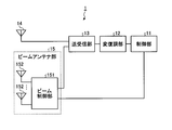
- FIG. 1 is a diagram illustrating a configuration example of a base station which is a communication apparatus according to the present invention.
- a base station 1 shown in FIG. 1 constitutes a wireless communication system together with a terminal to be described later, and transmits and receives data to and from the terminal using a beam formed by beam forming.
- the base station 1 includes a control unit 11, a modem unit 12, a transmission / reception unit 13, an omni antenna 14, and a beam antenna unit 15.
- the beam antenna unit 15 includes a beam control unit 151 and a plurality of antennas 152.
- the control unit 11 collects reception quality information when signals are transmitted using each of a plurality of beams from terminals in the service area covered by the own device, and based on the collected information. Determine the beam to use when communicating with the terminal.
- the reception quality information collected by the control unit 11 is used as the reception power level of the signal, but the present invention is not limited to this.
- the modulation / demodulation unit 12 modulates control information or data to be transmitted to the terminal when input from the control unit 11, and demodulates it when a reception signal from the terminal is input from the transmission / reception unit 13.
- the transmission / reception unit 13 When the signal is input from the modulation / demodulation unit 12, the transmission / reception unit 13 performs a transmission process of converting from digital to analog and up-converting to a radio frequency signal (hereinafter, referred to as a radio signal), and the radio signal received from the terminal is received.
- a radio signal a radio frequency signal
- the omni antenna 14 or the beam antenna unit 15 When it is input from the omni antenna 14 or the beam antenna unit 15, it performs down-conversion to a baseband signal and executes a reception process for converting from analog to digital.
- the omni antenna 14 transmits and receives radio signals to and from the terminal.
- the omni antenna 14 is mainly used when transmitting / receiving control information.
- the beam antenna unit 15 forms a beam in the direction in which the terminal exists and transmits / receives a radio signal to / from the terminal.
- the beam antenna unit 15 is mainly used in communication for transmitting / receiving data to / from a terminal.
- the beam control unit 151 of the beam antenna unit 15 forms one or more beams using some or all of the plurality of antennas 152 in accordance with instructions from the control unit 11.
- the beam control unit 151 selects and controls a directional beam by antenna selection or antenna adjustment.
- the beam control unit 151 is an electronic circuit configured to include, for example, an amplifier and a phase shifter.
- the beam control unit 151 distributes signals input from the transmission / reception unit 13 to the plurality of antennas 152, and signals received by the antennas 152. Are output to the transmitter / receiver 13.
- the plurality of antennas 152 are, for example, element antennas that constitute an array antenna.
- the modem unit 12 may perform the encoding process for the transmission signal to the terminal and the decoding process for the reception signal from the terminal. Although the transmission data to the terminal is input to the modem unit 12 via the control unit 11, the transmission data may be input to the modem unit 12 without using the control unit 11.
- the control unit 11, the modulation / demodulation unit 12, the transmission / reception unit 13, and the beam antenna unit 15 constitute a measurement signal transmission unit.
- the control unit 11 also operates as a beam determination unit.
- the service area covered by the base station 1 is expressed as “the service area of the base station 1” in order to prevent the expression from becoming difficult to understand.
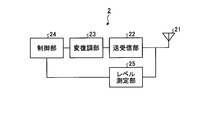
- FIG. 2 is a diagram illustrating a configuration example of a terminal that constitutes a wireless communication system together with the base station 1.
- the terminal 2 shown in FIG. 2 includes an antenna 21, a transmission / reception unit 22, a modulation / demodulation unit 23, a control unit 24, and a level measurement unit 25.
- the antenna 21 transmits and receives radio signals to and from the base station 1 shown in FIG.
- the transmission / reception unit 22 converts from digital to analog when the signal is input from the modulation / demodulation unit 23, and up-converts the signal to a radio signal. Convert and convert from analog to digital.
- the modulation / demodulation unit 23 modulates control information or data to be transmitted to the base station 1 when input from the control unit 24, and demodulates it when a reception signal from the base station 1 is input from the transmission / reception unit 22.
- the control unit 24 collects information necessary for the base station 1 to determine a beam to be used for communication with its own device and transmits the information to the base station 1.
- the level measurement unit 25 measures the reception power level (hereinafter referred to as reception level) of the radio signal received by the antenna 21.
- the base station 1 transmits a signal using a plurality of beams to all areas in the service area of the own device, and sets the reception level to the terminal 2 as the reception quality of the transmitted signal. Let me measure.
- the terminal 2 notifies the measurement result to the base station 1, and the base station 1 communicates with the terminal 2 based on the measurement result notified from the terminal 2. Decide which beam to use for communication.
- the base station 1 identifies the position where the terminal 2 exists based on the measurement result notified from the terminal 2, that is, in which beam irradiation direction the terminal 2 exists. Then, it is determined to use a beam whose irradiation direction matches the direction in which the terminal 2 exists, or a beam whose irradiation direction is close to the direction in which the terminal 2 exists. Note that there may be a plurality of terminals in the service area of the base station 1, and in such a case, the base station 1 determines a beam to be used for communication with each terminal for each terminal.
- the base station 1 is limited in the number of beams that can be formed at the same time due to the size of the device, the cost, the size of the service area to be covered, and other reasons, and is received for all areas within the service area of the own device. It may be difficult to send quality measurement signals all at once. In such a case, the base station 1 transmits the reception quality measurement signal a plurality of times, and transmits the reception quality measurement signal to the entire area within the service area of the base station 1.
- FIG. 3 is a diagram illustrating an example of an operation in which the base station 1 executes transmission of a reception quality measurement signal a plurality of times.
- the number of beams N that can be simultaneously formed by the base station 1 is 9, and the number of beams M necessary for uniformly irradiating the entire area of the service area of the base station 1 is 18
- the base station 1 needs to transmit the signal for reception quality measurement in two steps in order to transmit it uniformly over the entire service area. Therefore, in the first signal transmission, the base station 1 irradiates the beam in the direction of the irradiation pattern B1 shown in FIG. 3, that is, the hatched areas B11 to B19. In the second signal transmission, The beam is irradiated to the direction of the irradiation pattern B2, that is, the hatched regions B21 to B29.
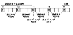
- FIG. 4 is a diagram showing an example of the execution timing of the first beam irradiation and the second beam irradiation shown in FIG.
- the base station 1 irradiates the beam in the direction of the irradiation pattern B1 shown in FIG. 3 at timing T1, and irradiates the beam in the direction of the irradiation pattern B2 at timing T2.
- the communication dedicated time zone other than the timings T1 and T2 is not a time zone for transmitting a reception quality measurement signal but a time zone for normal communication.
- Normal communication includes transmission / reception of data between the base station 1 and the terminal 2.
- the base station 1 uses a beam corresponding to the position of the communication partner terminal 2.
- the base station 1 periodically performs the beam irradiation in the direction of the irradiation pattern B1 and the beam irradiation in the direction of the irradiation pattern B2, that is, every time the measurement signal transmission period elapses, and performs reception quality measurement. Is transmitted to all areas of the service area. Thereby, when the terminal 2 moves, the base station 1 can grasp the position after the movement, and can continue communication with the terminal 2 using an optimum beam.
- the adjacent beam irradiation directions are different irradiation patterns (B1 and B2), but the irradiation pattern is not necessarily limited to this.
- the execution timing of the first beam irradiation and the second beam irradiation is set as the adjacent time timing, but the timing shown in FIG. 6, that is, the first beam irradiation is performed.
- a communication dedicated time zone may be provided between the timing and the timing of the second beam irradiation.
- the measurement signal transmission cycle is determined based on the maximum moving speed of the terminal 2 in the service area of the base station 1. Specifically, the cycle is shortened if the maximum movement speed of the terminal 2 is fast, and the cycle is lengthened if the maximum movement speed is slow. It is assumed that the maximum moving speed of the terminal 2 is determined in advance according to the installation position of the base station 1. When the base station 1 is installed near a highway, a main road, or a high-speed railway track, the maximum movement speed of the terminal 2 is increased. In this case, the measurement signal transmission cycle of the base station 1 is shortened. .
- the maximum moving speed of the terminal 2 is estimated to be slow. Lengthen.
- a specific value of the measurement signal transmission cycle may be a rough value according to the maximum moving speed of the terminal 2. For example, it is good also as three types of values, the period when the maximum moving speed is fast, the period when it is slow, and the period when it is intermediate between when it is fast and when it is slow. Further, a specific value of the measurement signal transmission cycle may be calculated from the maximum moving speed of the terminal 2.
- the maximum moving speed used in the calculation may be determined based on, for example, the maximum speed of an automobile or a railway vehicle, that is, based on the speed limit in a section near the installation position of the base station 1.
- a service provider that provides the communication system may make a determination based on a speed that is lower than the maximum speed of the automobile or railway vehicle where the base station 1 is installed, according to the service policy.
- FIG. 7 is a sequence diagram illustrating an example of a procedure in which the base station 1 determines a beam to be used for communication with the terminal 2.
- the base station 1 notifies the terminal 2 in advance of search information for the terminal 2 to perform a receiving operation and detect a beam (step S1).
- the search information includes a timing at which the base station 1 transmits a reference signal, which is a signal for measuring reception quality, using a beam, that is, a timing at which the terminal 2 should search for a beam emitted from the base station 1, a beam And the like, the reference signal pattern of the beam to be detected by the terminal 2 in the reception operation, the correspondence relationship between the reference signal pattern and the beam ID, and the like.
- the timing at which the base station 1 transmits the reference signal with the beam includes, for example, the timing at which the reference signal is first transmitted and the reference signal transmission period, that is, the measurement signal transmission period illustrated in FIGS. 4 and 6. Information.
- the timing at which the reference signal is first transmitted can be specified, for example, by the elapsed time from when the search information is transmitted until the reference signal is first transmitted. Further, the same can be realized by placing the frame number at the time of transmission when transmitting the search information and notifying the frame number of the first transmission of the reference signal. Alternatively, if the reference signal is transmitted every time the reference signal transmission cycle elapses with reference to the timing at which the search information is transmitted, the base station 1 transmits “reference signal transmitted by beam included in the search information. It is only necessary to notify the terminal 2 of the reference signal transmission cycle (measurement signal transmission cycle).
- the base station 1 uses the omni antenna 14 and transmits search information by broadcasting.
- the search information transmitted from the omnidirectional omni antenna 14 reaches all the terminals 2 existing in the service area of the base station 1 and is received by the terminals 2.
- the reference signal pattern (bit pattern) is a fixed and different pattern for each beam, and a beam ID that is beam identification information is associated with the reference signal pattern. Therefore, if the reference signal pattern is known, it is possible to grasp which beam is used to transmit the reference signal pattern.
- the base station 1 periodically performs the process of step S1, that is, notification of search information. Further, if the search information can be surely notified to all the terminals 2 in the service area, the base station 1 may notify the search information to the terminals 2 via another communication network.
- the base station 1 uses a plurality of beams to direct all the regions in the service area.
- the reference signal is transmitted (steps S2a and S2b).
- the reference signal is a reception quality measurement signal.
- the base station 1 transmits a reference signal using the beam of the irradiation pattern B1 in step S2a, and transmits a reference signal using the beam of the irradiation pattern B2 in step S2b.
- the terminal 2 receives the reference signal transmitted by each beam and transmits the reference signal. Measure the reception level and detect the beam. Then, the terminal 2 reports the beam detection result to the base station 1 (step S3). At this time, the terminal 2 may report the beam IDs of all the beams and the reception levels corresponding to them as the beam detection results, or a prescribed number of beam IDs and reception levels in order from the highest reception level. May be reported.
- the base station 1 determines a beam to be used for communication with the reporting source terminal 2 based on the reported detection result (step S4).
- the reported detection result is a detection result reported from all the terminals 2 in the service area.
- the base station 1 determines, for each terminal 2, a beam to be used for communication with each terminal 2 based on each reported detection result for each terminal 2. Determine individually. For example, the base station 1 determines to use a beam having the highest reception level at a certain terminal 2 in communication with the terminal 2.
- Steps S2a, S2b, and S3 shown in FIG. 7 are processes for the base station 1 to grasp where the terminal 2 exists in the service area of its own device. It can be said that it is a process of searching. Therefore, in the following description, the processes in steps S2a, S2b, and S3 may be collectively expressed as a terminal search or a search process.
- the base station 1 may receive the beam detection result reported from the terminal 2 in step S3 by the omni antenna 14 or the beam antenna unit 15.
- the base station 1 sets the above-mentioned timing so that the detection result report timing of the beam irradiated with the irradiation pattern B1 is different from the detection result report timing of the beam irradiated with the irradiation pattern B2.
- the terminal 2 is instructed by the search information.
- the base station 1 forms the beam of the irradiation pattern B1 at the detection result report timing of the beam transmitted in the irradiation pattern B1, and performs reception processing, and the irradiation pattern B2 at the detection result report timing of the beam transmitted in the irradiation pattern B2.
- the beam is formed and reception processing is performed.
- the report timing of the terminal is reported in the search information.
- the report timing may be different for each terminal, in that case, after the search information is broadcast, the report timing is individually reported for each terminal. do it.
- different communication parameters are set individually for each terminal before communication. Can do.
- the base station 1 and the terminal 2 periodically execute the above steps S2a to S4.
- the execution cycle of steps S2a to S4 corresponds to the “measurement signal transmission cycle” described above.
- the base station 1 repeatedly executes step S1 with a period longer than the execution period of steps S2a to S4.
- FIG. 8 is a flowchart illustrating an operation example of the control unit 11 when the base station 1 transmits a reference signal toward all areas in the service area using a plurality of beams.
- the flowchart of FIG. 8 shows an operation example when the control unit 11 operates as a measurement signal transmission unit.
- the operation shown in FIG. 8 corresponds to the operations of steps S1, S2a, and S2b shown in FIG.
- the control unit 11 of the base station 1 confirms whether or not the search information transmission timing is reached (step S11), and if it is the transmission timing (step S11: Yes), the search information is broadcast and transmitted within the service area of the own device. (Step S12). The control part 11 returns to step S11 after performing step S12.
- step S11 when it is not the transmission timing of the search information (step S11: No), the control unit 11 confirms whether it is the transmission timing of the reference signal (step S13). The control part 11 returns to step S11, when it is not the transmission timing of a reference signal (step S13: No). In the case of the transmission timing of the reference signal (step S13: Yes), the controller 11 checks whether or not it is the first beam irradiation timing, that is, whether or not it is the beam irradiation timing in the irradiation pattern B1 (step S14). In the case of the first beam irradiation timing (step S14: Yes), the control unit 11 performs the first beam irradiation (step S15).
- the control unit 11 instructs the beam antenna unit 15 to irradiate the beam according to the irradiation pattern B1 indicating the first beam irradiation direction, and outputs a reference signal to be transmitted with each irradiated beam to the modem unit 12. .
- the reference signal output to the modulation / demodulation unit 12 is modulated by the modulation / demodulation unit 12, converted into an analog radio signal by the transmission / reception unit 13, and then input to the beam antenna unit 15.
- the beam antenna unit 15 forms a beam in accordance with an instruction from the control unit 11, assigns a reference signal input as an analog radio signal from the transmission / reception unit 13 to each beam, and transmits the beam.
- step S16 the control unit 11 instructs the beam antenna unit 15 to irradiate the beam according to the irradiation pattern B2 indicating the second beam irradiation direction, and outputs a reference signal transmitted by the irradiated beam to the modem unit 12.
- the operations of the modem unit 12, the transmitter / receiver unit 13, and the beam antenna unit 15 at this time are the same as those in step S15.
- step S14 the control unit 11 confirms the number of times of irradiation and instructs the beam antenna unit 15 to irradiate the beam with the irradiation pattern corresponding to the confirmation result.
- FIG. 9 is a flowchart illustrating an operation example when the control unit 11 of the base station 1 determines a beam to be used based on the beam detection result in the terminal 2.
- the flowchart in FIG. 9 illustrates an operation example when the control unit 11 operates as a beam determination unit.
- the operation shown in FIG. 9 corresponds to the operation in step S3 and the operation in step S4 shown in FIG. Therefore, the operation shown in FIG. 9 starts after the reference signal is transmitted.
- control unit 11 of the base station 1 confirms whether it is time to receive the beam detection result in the terminal 2 (step S21). When it is not the reception timing of the detection result (step S21: No), the control unit 11 repeats step S21 until the reception timing is reached.
- the control unit 11 receives the beam detection result from the terminal 2 in the case of the detection result reception timing (step S21: Yes) (step S22). That is, the control unit 11 receives the beam detection result transmitted from the terminal 2 via the omni antenna 14 or the beam antenna unit 15, the transmission / reception unit 13, and the modem unit 12. At this time, the transmission / reception unit 13 down-converts the analog radio signal input from the omni antenna 14 or the beam antenna unit 15 into a baseband signal, converts the analog signal into digital, and outputs the converted signal to the modulation / demodulation unit 12. The modem unit 12 demodulates the signal input from the transmission / reception unit 13 and outputs the demodulated signal to the control unit 11.
- the control unit 11 receives beam detection results from all the terminals 2 in the service area in step S22. Upon receiving the beam detection result, the control unit 11 determines a beam to be used for communication with each terminal 2 in the service area based on the received detection result (step S23). For example, the control unit 11 determines to use the beam having the highest reception level at the terminal 2. Also, instead of determining from a single detection result, for example, based on a plurality of detection results including the past several detection results, for example, the beam having the highest average value of the plurality of reception levels is used. It is also possible to decide.
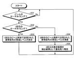
- FIG. 10 is a flowchart showing an operation example of the control unit 24 when the terminal 2 searches for the beam irradiated from the base station 1 and reports the search result, that is, the beam detection result to the base station 1.
- the operation shown in FIG. 10 corresponds to the operations of steps S2a, S2b and S3 shown in FIG.
- the control unit 24 of the terminal 2 confirms whether or not it is the beam search timing (step S31), and if it is not the search timing (step S31: No), repeats step S31 until the search timing is reached.
- the control unit 24 checks whether or not it is the first search timing (step S32).
- the control unit 24 receives and receives the reference signal transmitted by each beam irradiated for the first time via the transmission / reception unit 22 and the modem unit 23. Information on the reception level of the reference signal is acquired from the level measuring unit 25 (step S33).
- step S33 ends, the control unit 24 returns to step S31.
- the control unit 24 receives the reference signal transmitted by each beam irradiated for the second time through the transmission / reception unit 22 and the modem unit 23, Information on the reception level of the received reference signal is acquired from the level measurement unit 25 (step S34).
- the control unit 24 reports the reception result of the first reference signal and the reception result of the second reference signal as a beam detection result to the base station 1 via the modulation / demodulation unit 23, the transmission / reception unit 22, and the antenna 21.
- the information reported as the beam detection result is the beam ID of the detected beam and the beam reception level.
- the control unit 24 can detect only a part of the beam emitted from the base station 1.
- control unit 24 may report only the beam ID and the reception level of the detected beam to the base station 1 in step S35 described above. For the beam that could not be detected, instead of the reception level, It may be reported that the beam could not be detected. After executing Step S35, the control unit 24 returns to Step S31.
- the base station 1 is individually provided with the omni antenna 14 for broadcasting search information and the like and the beam antenna unit 15 for beam formation, one antenna unit has these functions. It is also possible to make it.
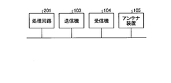
- FIG. 11 is a diagram illustrating an example of a hardware configuration for realizing the base station 1 and the terminal 2.
- the base station 1 is realized by, for example, the processor 101, the memory 102, the transmitter 103, the receiver 104, and the antenna device 105 illustrated in FIG.
- the processor 101 is a CPU (Central Processing Unit, central processing unit, processing unit, arithmetic unit, microprocessor, microcomputer, processor, DSP (Digital Signal Processor)), system LSI (Large Scale Integration), or the like.
- CPU Central Processing Unit
- processing unit processing unit
- arithmetic unit microprocessor
- microcomputer processor
- DSP Digital Signal Processor
- system LSI Large Scale Integration
- the memory 102 is a nonvolatile or volatile semiconductor such as RAM (Random Access Memory), ROM (Read Only Memory), flash memory, EPROM (Erasable Programmable Read Only Memory), EEPROM (Electrically Erasable Programmable Read-Only Memory), etc. Memory, magnetic disk, flexible disk, optical disk, compact disk, mini disk, DVD (Digital Versatile Disc), etc.
- the control unit 11 and the modem unit 12 of the base station 1 are realized by programs stored in the processor 101 and the memory 102. Specifically, it is realized by the processor 101 reading out a program for operating the control unit 11 and the modem unit 12 from the memory 102 and executing the program.
- the transmission / reception unit 13 of the base station 1 is realized by the transmitter 103 and the receiver 104. That is, transmission processing in the transmission / reception unit 13 is performed in the transmitter 103, and reception processing in the transmission / reception unit 13 is performed in the receiver 104.
- the omni antenna 14 and the beam antenna unit 15 of the base station 1 are realized by the antenna device 105.
- the omni antenna 14 and the beam antenna unit 15 may be realized by different antenna devices.
- the control unit 24 and the modem unit 23 of the terminal 2 are realized by programs stored in the processor 101 and the memory 102. Specifically, the processing is realized by the processor 101 reading a program for operating the control unit 24 and the modem unit 23 from the memory 102 and executing the program.
- the transmission / reception unit 22 of the terminal 2 is realized by the transmitter 103 and the receiver 104. That is, transmission processing in the transmission / reception unit 22 is performed in the transmitter 103, and reception processing in the transmission / reception unit 22 is performed in the receiver 104.
- the level measuring unit 25 of the terminal 2 is realized by the receiver 104. Further, the antenna 21 of the terminal 2 is realized by the antenna device 105.
- control unit 11 and the modulation / demodulation unit 12 of the base station 1 and the control unit 24 and the modulation / demodulation unit 23 of the terminal 2 may be realized by dedicated hardware, and some of them are realized by dedicated hardware, and the rest May be realized by software, firmware, or a combination of software and firmware.
- the hardware configuration of the base station 1 and the terminal 2 when these units are realized by dedicated hardware is, for example, as shown in FIG. That is, the control unit 11 and the modem unit 12 of the base station 1 and the control unit 24 and the modem unit 23 of the terminal 2 are realized by the processing circuit 201.
- the processing circuit 201 may be, for example, a single circuit, a composite circuit, a programmed processor, a parallel programmed processor, an ASIC (Application Specific Integrated Circuit), an FPGA (Field Programmable Gate Array), or a combination thereof.
- ASIC Application Specific Integrated Circuit
- FPGA Field Programmable Gate Array
- FIG. 13 is a diagram illustrating an example of arrangement of reference signals to each beam emitted by the base station 1.
- RS is a reference signal.
- the reference signal is a signal transmitted from the base station 1 into the service area of the own device in the terminal search described above.
- the example shown in FIG. 13 shows a case where a reference signal is transmitted using a part of the frequency resource in each beam, and the remaining frequency resources where no reference signal is arranged are used for communication. However, it is limited to communication with a terminal existing in the beam irradiation direction.
- the frequency resources at two locations in each beam are used for reference signal transmission.
- the measurement results at the two locations are averaged, which is specific to wireless communication. This is to avoid instantaneous fluctuations in level due to fading and to enable more stable measurement. Therefore, in the example of FIG. 13, two frequency resources are used, but three or more frequency resources may be used. Further, as shown in the lower part of FIG.
- the position where the reference signal is arranged for each beam is changed in fine units in the time axis direction within one frequency resource.
- 3GPP The definition of resources by standardized LTE (Long Term Evolution) in (3 rd Generation Partnership Project), a plurality of OFDM (Orthogonal Frequency Division Multiplexing) in the time unit of resource allocation that TTI (Transmission Time Interval) Symbol There is a unit.
- LTE Long Term Evolution
- OFDM Orthogonal Frequency Division Multiplexing
- TTI Transmission Time Interval
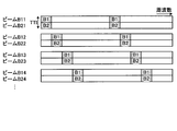
- the reference signals are arranged using resources at the same frequency position in all the beams, but the arrangement shown in FIG. 14 is also possible.
- the position of the frequency resource in which the reference signal is arranged is changed for each beam.
- reference signals can be transmitted with a plurality of beams at the same time.
- the beams B11, B12, B13, B14,... Of the irradiation pattern B1 and the beams B21, B22, B23, B24,... Of the irradiation pattern B2 are switched within one TTI. ing.
- the time required for the terminal search is shortened, and the base station 1 can shorten the time required for determining the optimum beam to be used for communication with the terminal 2. Therefore, when the terminal 2 moves, the used beam can be switched in a short time. In addition, resources required for terminal search can be reduced.
- the number of beams irradiated by the base station 1 in one terminal search (hereinafter referred to as the number of beam irradiations) is determined by the average reception level of the service area and the reference signal transmission at the search timing, that is, the timing of starting the terminal search. It is determined by the trade-off of communication time rate after allocating time resources.
- the call time rate is a ratio of a period in which the base station 1 and the terminal 2 can communicate with each other in a certain period, and is a ratio of a period that is not used for reference signal transmission in another expression.
- FIG. 16A shows an example in which a service area surrounded by a dotted line is covered with 9 beams.
- the edge of each circle shown in the figure indicates, for example, a position 3 dB lower than the maximum gain obtained in the direction in which the center of the beam is directed. In this case, there is a gain reduction of 3 dB or more at a position outside the circle, and when the terminal 2 receives a signal from the base station 1 at a position outside the circle, the reception level becomes low.
- FIG. 16B shows an example in which the service area is covered with 16 beams. In the example of FIG.
- the reception level when the terminal 2 receives a signal from the base station 1 is higher than that in the case of FIG.
- the reception level is high, a modulation scheme with a high modulation degree capable of sending many bits at a time can be used, and thus the throughput during communication tends to be high.
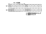
- FIG. 17 is a diagram illustrating a relationship between a search cycle that is a terminal search execution cycle and a timing at which a reference signal is transmitted in the terminal search.
- the search cycle corresponds to the above-described “measurement signal transmission cycle”.
- FIG. 17A shows a case where the reference signal transmission timing exists once per search cycle
- FIG. 7B shows a case where the reference signal transmission timing exists twice per search cycle. Yes. Since communication is performed at times other than the transmission timing of the reference signal, the number of timings that can be used for communication is reduced in FIG. In this case, the throughput during communication tends to be low.
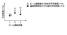
- FIG. 18 is a diagram showing a specific example of a method for determining the number of beam irradiations per terminal search.
- the horizontal axis indicates the number of beam irradiation executions per one terminal search (number of beam irradiations), and the vertical axis indicates the average reception level in the service area.
- the white plot shows the average reception level in the service area at each number of beam irradiations.
- FIG. 18 shows an example in which the number of beams that can be irradiated by one beam irradiation is nine.
- the average reception level when the service area is covered with 9 beams when the number of beam irradiations is 1, the average reception level when the service area is covered with 9 beams, when the number of beam irradiations is 2, the average reception level when the service area is covered with 18 beams, and the beam irradiation When the number of times is 3, the average reception level when the service area is covered by 27 beams is used.
- the black plot is the result of multiplying the result of the white plot by the communication time rate.
- the method for determining the number of beam irradiations is not limited to this. It may be determined by other methods.
- the number of beam irradiations per terminal search in each base station 1 constituting the wireless communication system may be determined by simulation in consideration of the installation position of each base station 1. After 1 is actually installed, it may be determined based on a search cycle, an actual measurement value of the average reception level, and the like.
- the base station 1 transmits a reference signal to all areas of the service area of its own device using a plurality of beams, and the terminal 2 based on the reception result of the reference signal in the terminal 2
- the process of determining the beam to be used for communication with the terminal 2 is repeatedly executed in a cycle based on the maximum moving speed of the terminal 2. Thereby, even if the terminal 2 moves, the base station 1 can continue the communication using the beam most suitable for the terminal 2.
- the process for determining the beam to be used is executed in a cycle based on the maximum movement speed of the terminal 2, the process for determining the beam to be used can be frequently executed even though the movement speed of the terminal 2 is low. Disappear. That is, unnecessary terminal search operation can be eliminated, terminal search (determination of a beam to be used) can be performed efficiently, and waste of communication resources can be prevented.
- the base station 1 when the number of beams that can be simultaneously generated by the base station 1 is limited, a plurality of beam irradiation timings are provided, and the base station 1 irradiates the beams by changing the beam direction at each timing.
- the terminal 2 measures the reception level of each beam at all the plurality of beam irradiation timings and reports the measurement result to the base station 1. Thereby, the base station 1 can select an optimum beam no matter where the terminal 2 exists in the service area.
- the reference signal used in the terminal search is not embedded in all frequency resources or time resources in each beam, but is embedded in some resources. That is, the reference signal is transmitted using some communication resources. At this time, communication resources that are not used in the transmission of the reference signal are used for transmission of the communication signal. Thereby, it is possible to minimize a decrease in throughput due to the execution of the terminal search.
- the configuration described in the above embodiment shows an example of the contents of the present invention, and can be combined with another known technique, and can be combined with other configurations without departing from the gist of the present invention. It is also possible to omit or change the part.
Landscapes
- Engineering & Computer Science (AREA)
- Computer Networks & Wireless Communication (AREA)
- Signal Processing (AREA)
- Mobile Radio Communication Systems (AREA)
Abstract
La présente invention concerne un dispositif de communication fonctionnant comme une station de base pour communiquer avec un terminal en utilisant un faisceau, le dispositif de communication comportant: une unité d'émission de signal de mesure (unité 11 de commande, unité 12 de modulation/démodulation, une unité 13 d'émission/réception, une unité 15 d'antenne de faisceau) servant à exécuter cycliquement un processus d'émission de signal de mesure visant à envoyer, en utilisant une pluralité de faisceaux, un signal de mesure de la qualité de réception à toute la région située à l'intérieur d'une zone de desserte couverte par le dispositif, et une unité de détermination de faisceau (unité 11 de commande) servant à déterminer le faisceau utilisé pour la communication avec un terminal d'après la qualité de réception de faisceaux individuels du signal de mesure de la qualité de réception au niveau du terminal.
Priority Applications (2)
| Application Number | Priority Date | Filing Date | Title |
|---|---|---|---|
| PCT/JP2015/069691 WO2017006470A1 (fr) | 2015-07-08 | 2015-07-08 | Dispositif de communication et procédé de sélection de faisceau |
| JP2017527043A JP6541783B2 (ja) | 2015-07-08 | 2015-07-08 | 通信装置およびビーム選択方法 |
Applications Claiming Priority (1)
| Application Number | Priority Date | Filing Date | Title |
|---|---|---|---|
| PCT/JP2015/069691 WO2017006470A1 (fr) | 2015-07-08 | 2015-07-08 | Dispositif de communication et procédé de sélection de faisceau |
Publications (1)
| Publication Number | Publication Date |
|---|---|
| WO2017006470A1 true WO2017006470A1 (fr) | 2017-01-12 |
Family
ID=57685148
Family Applications (1)
| Application Number | Title | Priority Date | Filing Date |
|---|---|---|---|
| PCT/JP2015/069691 Ceased WO2017006470A1 (fr) | 2015-07-08 | 2015-07-08 | Dispositif de communication et procédé de sélection de faisceau |
Country Status (2)
| Country | Link |
|---|---|
| JP (1) | JP6541783B2 (fr) |
| WO (1) | WO2017006470A1 (fr) |
Cited By (4)
| Publication number | Priority date | Publication date | Assignee | Title |
|---|---|---|---|---|
| JP2020511850A (ja) * | 2017-03-23 | 2020-04-16 | コンヴィーダ ワイヤレス, エルエルシー | New Radioにおけるダウンリンク測定設計 |
| JP2021511710A (ja) * | 2018-01-11 | 2021-05-06 | テレフオンアクチーボラゲット エルエム エリクソン(パブル) | ビーム障害回復のためのコンテンションベースランダムアクセス |
| JP2021536154A (ja) * | 2018-07-06 | 2021-12-23 | 日本電気株式会社 | ネットワーク機器で実施される方法及び端末機器で実施される方法 |
| CN116192221A (zh) * | 2018-02-08 | 2023-05-30 | 三菱电机株式会社 | 无线终端、控制电路以及非暂时性程序存储装置 |
Citations (6)
| Publication number | Priority date | Publication date | Assignee | Title |
|---|---|---|---|---|
| JPH10190569A (ja) * | 1996-11-08 | 1998-07-21 | Lucent Technol Inc | ビーム形成方法及び読み出し可能記録媒体 |
| JP2003152610A (ja) * | 2001-11-19 | 2003-05-23 | Hitachi Ltd | 無線通信装置 |
| JP2007336547A (ja) * | 2006-06-12 | 2007-12-27 | Hitachi Ltd | 無線システム、基地局装置および端末装置 |
| JP2010534020A (ja) * | 2007-07-16 | 2010-10-28 | ノーテル・ネットワークス・リミテッド | 無線ネットワークでの空間分割多重アクセスの提供 |
| JP2012227686A (ja) * | 2011-04-19 | 2012-11-15 | Kyocera Corp | 基地局、周辺基地局及び通信システム |
| US20140112220A1 (en) * | 2012-10-24 | 2014-04-24 | Samsung Electronics Co., Ltd. | Method and apparatus for transmitting and receiving common channel information in wireless communication system |
Family Cites Families (1)
| Publication number | Priority date | Publication date | Assignee | Title |
|---|---|---|---|---|
| JP6266929B2 (ja) * | 2013-09-06 | 2018-01-24 | 株式会社Nttドコモ | 同期方法、移動局装置及び基地局装置 |
-
2015
- 2015-07-08 WO PCT/JP2015/069691 patent/WO2017006470A1/fr not_active Ceased
- 2015-07-08 JP JP2017527043A patent/JP6541783B2/ja active Active
Patent Citations (6)
| Publication number | Priority date | Publication date | Assignee | Title |
|---|---|---|---|---|
| JPH10190569A (ja) * | 1996-11-08 | 1998-07-21 | Lucent Technol Inc | ビーム形成方法及び読み出し可能記録媒体 |
| JP2003152610A (ja) * | 2001-11-19 | 2003-05-23 | Hitachi Ltd | 無線通信装置 |
| JP2007336547A (ja) * | 2006-06-12 | 2007-12-27 | Hitachi Ltd | 無線システム、基地局装置および端末装置 |
| JP2010534020A (ja) * | 2007-07-16 | 2010-10-28 | ノーテル・ネットワークス・リミテッド | 無線ネットワークでの空間分割多重アクセスの提供 |
| JP2012227686A (ja) * | 2011-04-19 | 2012-11-15 | Kyocera Corp | 基地局、周辺基地局及び通信システム |
| US20140112220A1 (en) * | 2012-10-24 | 2014-04-24 | Samsung Electronics Co., Ltd. | Method and apparatus for transmitting and receiving common channel information in wireless communication system |
Cited By (6)
| Publication number | Priority date | Publication date | Assignee | Title |
|---|---|---|---|---|
| JP2020511850A (ja) * | 2017-03-23 | 2020-04-16 | コンヴィーダ ワイヤレス, エルエルシー | New Radioにおけるダウンリンク測定設計 |
| US11510119B2 (en) | 2017-03-23 | 2022-11-22 | Ipla Holdings Inc. | Downlink measurement design in new radio |
| US11683734B2 (en) | 2017-03-23 | 2023-06-20 | Ipla Holdings Inc. | Downlink measurement design in new radio |
| JP2021511710A (ja) * | 2018-01-11 | 2021-05-06 | テレフオンアクチーボラゲット エルエム エリクソン(パブル) | ビーム障害回復のためのコンテンションベースランダムアクセス |
| CN116192221A (zh) * | 2018-02-08 | 2023-05-30 | 三菱电机株式会社 | 无线终端、控制电路以及非暂时性程序存储装置 |
| JP2021536154A (ja) * | 2018-07-06 | 2021-12-23 | 日本電気株式会社 | ネットワーク機器で実施される方法及び端末機器で実施される方法 |
Also Published As
| Publication number | Publication date |
|---|---|
| JP6541783B2 (ja) | 2019-07-10 |
| JPWO2017006470A1 (ja) | 2018-02-15 |
Similar Documents
| Publication | Publication Date | Title |
|---|---|---|
| JP6525357B2 (ja) | ビーム送受信方法、基地局、端末、および無線通信システム | |
| US10064219B2 (en) | Method and apparatus for system access in system using beamforming | |
| KR102026256B1 (ko) | 빔포밍 시스템에서의 rach 신호 송수신 기법 | |
| WO2019154344A1 (fr) | Réception de canaux de liaison descendante dans un système de communication sans fil | |
| KR101937821B1 (ko) | 라디오 네트워크의 수직으로 섹터화된 셀을 서빙하는 안테나에 대한 경사각의 조절을 결정 | |
| JP6312742B2 (ja) | 基地局 | |
| CN109804654B (zh) | 波束发送接收方法、基站、终端以及无线通信系统 | |
| US11695534B2 (en) | Base station, terminal, wireless communication system, and transmission/reception method | |
| JP6377184B2 (ja) | 通信装置 | |
| JP6541783B2 (ja) | 通信装置およびビーム選択方法 | |
| KR20200082230A (ko) | 자원 관리를 위한 장치 및 방법 | |
| CN116192221A (zh) | 无线终端、控制电路以及非暂时性程序存储装置 | |
| US20160302090A1 (en) | Backhaul Beam Searching | |
| CN101621807A (zh) | 基站装置、频率分配方法以及利用其的移动通信系统 | |
| WO2018163230A1 (fr) | Terminal mobile, station de base sans fil et procédé de transmission et de réception de faisceau | |
| WO2024074357A1 (fr) | Planification et gestion de faisceau de transmissions sans fil avec charge utile de communication sur la base d'exigences de détection |
Legal Events
| Date | Code | Title | Description |
|---|---|---|---|
| 121 | Ep: the epo has been informed by wipo that ep was designated in this application |
Ref document number: 15897732 Country of ref document: EP Kind code of ref document: A1 |
|
| ENP | Entry into the national phase |
Ref document number: 2017527043 Country of ref document: JP Kind code of ref document: A |
|
| NENP | Non-entry into the national phase |
Ref country code: DE |
|
| 122 | Ep: pct application non-entry in european phase |
Ref document number: 15897732 Country of ref document: EP Kind code of ref document: A1 |