WO2020003948A1 - Machine de travail - Google Patents
Machine de travail Download PDFInfo
- Publication number
- WO2020003948A1 WO2020003948A1 PCT/JP2019/022409 JP2019022409W WO2020003948A1 WO 2020003948 A1 WO2020003948 A1 WO 2020003948A1 JP 2019022409 W JP2019022409 W JP 2019022409W WO 2020003948 A1 WO2020003948 A1 WO 2020003948A1
- Authority
- WO
- WIPO (PCT)
- Prior art keywords
- switch
- steering
- arm
- cabin
- pin
- Prior art date
- Legal status (The legal status is an assumption and is not a legal conclusion. Google has not performed a legal analysis and makes no representation as to the accuracy of the status listed.)
- Ceased
Links
Images


Classifications
-
- B—PERFORMING OPERATIONS; TRANSPORTING
- B62—LAND VEHICLES FOR TRAVELLING OTHERWISE THAN ON RAILS
- B62D—MOTOR VEHICLES; TRAILERS
- B62D49/00—Tractors
- B62D49/06—Tractors adapted for multi-purpose use
- B62D49/0692—Tractors adapted for multi-purpose use characterised by the particular arrangement of control devices, e.g. having more than one control stand, operable from vehicle extension (control devices or systems characterised by mechanical features only)
-
- B—PERFORMING OPERATIONS; TRANSPORTING
- B60—VEHICLES IN GENERAL
- B60R—VEHICLES, VEHICLE FITTINGS, OR VEHICLE PARTS, NOT OTHERWISE PROVIDED FOR
- B60R16/00—Electric or fluid circuits specially adapted for vehicles and not otherwise provided for; Arrangement of elements of electric or fluid circuits specially adapted for vehicles and not otherwise provided for
- B60R16/02—Electric or fluid circuits specially adapted for vehicles and not otherwise provided for; Arrangement of elements of electric or fluid circuits specially adapted for vehicles and not otherwise provided for electric constitutive elements
- B60R16/023—Electric or fluid circuits specially adapted for vehicles and not otherwise provided for; Arrangement of elements of electric or fluid circuits specially adapted for vehicles and not otherwise provided for electric constitutive elements for transmission of signals between vehicle parts or subsystems
- B60R16/027—Electric or fluid circuits specially adapted for vehicles and not otherwise provided for; Arrangement of elements of electric or fluid circuits specially adapted for vehicles and not otherwise provided for electric constitutive elements for transmission of signals between vehicle parts or subsystems between relatively movable parts of the vehicle, e.g. between steering wheel and column
-
- B—PERFORMING OPERATIONS; TRANSPORTING
- B60—VEHICLES IN GENERAL
- B60K—ARRANGEMENT OR MOUNTING OF PROPULSION UNITS OR OF TRANSMISSIONS IN VEHICLES; ARRANGEMENT OR MOUNTING OF PLURAL DIVERSE PRIME-MOVERS IN VEHICLES; AUXILIARY DRIVES FOR VEHICLES; INSTRUMENTATION OR DASHBOARDS FOR VEHICLES; ARRANGEMENTS IN CONNECTION WITH COOLING, AIR INTAKE, GAS EXHAUST OR FUEL SUPPLY OF PROPULSION UNITS IN VEHICLES
- B60K35/00—Instruments specially adapted for vehicles; Arrangement of instruments in or on vehicles
- B60K35/10—Input arrangements, i.e. from user to vehicle, associated with vehicle functions or specially adapted therefor
-
- B—PERFORMING OPERATIONS; TRANSPORTING
- B60—VEHICLES IN GENERAL
- B60K—ARRANGEMENT OR MOUNTING OF PROPULSION UNITS OR OF TRANSMISSIONS IN VEHICLES; ARRANGEMENT OR MOUNTING OF PLURAL DIVERSE PRIME-MOVERS IN VEHICLES; AUXILIARY DRIVES FOR VEHICLES; INSTRUMENTATION OR DASHBOARDS FOR VEHICLES; ARRANGEMENTS IN CONNECTION WITH COOLING, AIR INTAKE, GAS EXHAUST OR FUEL SUPPLY OF PROPULSION UNITS IN VEHICLES
- B60K35/00—Instruments specially adapted for vehicles; Arrangement of instruments in or on vehicles
- B60K35/50—Instruments characterised by their means of attachment to or integration in the vehicle
- B60K35/53—Movable instruments, e.g. slidable
-
- B—PERFORMING OPERATIONS; TRANSPORTING
- B60—VEHICLES IN GENERAL
- B60K—ARRANGEMENT OR MOUNTING OF PROPULSION UNITS OR OF TRANSMISSIONS IN VEHICLES; ARRANGEMENT OR MOUNTING OF PLURAL DIVERSE PRIME-MOVERS IN VEHICLES; AUXILIARY DRIVES FOR VEHICLES; INSTRUMENTATION OR DASHBOARDS FOR VEHICLES; ARRANGEMENTS IN CONNECTION WITH COOLING, AIR INTAKE, GAS EXHAUST OR FUEL SUPPLY OF PROPULSION UNITS IN VEHICLES
- B60K35/00—Instruments specially adapted for vehicles; Arrangement of instruments in or on vehicles
- B60K35/60—Instruments characterised by their location or relative disposition in or on vehicles
-
- B—PERFORMING OPERATIONS; TRANSPORTING
- B60—VEHICLES IN GENERAL
- B60K—ARRANGEMENT OR MOUNTING OF PROPULSION UNITS OR OF TRANSMISSIONS IN VEHICLES; ARRANGEMENT OR MOUNTING OF PLURAL DIVERSE PRIME-MOVERS IN VEHICLES; AUXILIARY DRIVES FOR VEHICLES; INSTRUMENTATION OR DASHBOARDS FOR VEHICLES; ARRANGEMENTS IN CONNECTION WITH COOLING, AIR INTAKE, GAS EXHAUST OR FUEL SUPPLY OF PROPULSION UNITS IN VEHICLES
- B60K35/00—Instruments specially adapted for vehicles; Arrangement of instruments in or on vehicles
- B60K35/65—Instruments specially adapted for specific vehicle types or users, e.g. for left- or right-hand drive
- B60K35/654—Instruments specially adapted for specific vehicle types or users, e.g. for left- or right-hand drive the user being the driver
-
- B—PERFORMING OPERATIONS; TRANSPORTING
- B60—VEHICLES IN GENERAL
- B60K—ARRANGEMENT OR MOUNTING OF PROPULSION UNITS OR OF TRANSMISSIONS IN VEHICLES; ARRANGEMENT OR MOUNTING OF PLURAL DIVERSE PRIME-MOVERS IN VEHICLES; AUXILIARY DRIVES FOR VEHICLES; INSTRUMENTATION OR DASHBOARDS FOR VEHICLES; ARRANGEMENTS IN CONNECTION WITH COOLING, AIR INTAKE, GAS EXHAUST OR FUEL SUPPLY OF PROPULSION UNITS IN VEHICLES
- B60K35/00—Instruments specially adapted for vehicles; Arrangement of instruments in or on vehicles
- B60K35/80—Arrangements for controlling instruments
-
- B—PERFORMING OPERATIONS; TRANSPORTING
- B62—LAND VEHICLES FOR TRAVELLING OTHERWISE THAN ON RAILS
- B62D—MOTOR VEHICLES; TRAILERS
- B62D1/00—Steering controls, i.e. means for initiating a change of direction of the vehicle
- B62D1/02—Steering controls, i.e. means for initiating a change of direction of the vehicle vehicle-mounted
- B62D1/16—Steering columns
-
- E—FIXED CONSTRUCTIONS
- E02—HYDRAULIC ENGINEERING; FOUNDATIONS; SOIL SHIFTING
- E02F—DREDGING; SOIL-SHIFTING
- E02F3/00—Dredgers; Soil-shifting machines
- E02F3/04—Dredgers; Soil-shifting machines mechanically-driven
- E02F3/28—Dredgers; Soil-shifting machines mechanically-driven with digging tools mounted on a dipper- or bucket-arm, i.e. there is either one arm or a pair of arms, e.g. dippers, buckets
- E02F3/36—Component parts
- E02F3/3604—Devices to connect tools to arms, booms or the like
- E02F3/3609—Devices to connect tools to arms, booms or the like of the quick acting type, e.g. controlled from the operator seat
- E02F3/3636—Devices to connect tools to arms, booms or the like of the quick acting type, e.g. controlled from the operator seat using two or four movable transversal pins
-
- E—FIXED CONSTRUCTIONS
- E02—HYDRAULIC ENGINEERING; FOUNDATIONS; SOIL SHIFTING
- E02F—DREDGING; SOIL-SHIFTING
- E02F3/00—Dredgers; Soil-shifting machines
- E02F3/04—Dredgers; Soil-shifting machines mechanically-driven
- E02F3/28—Dredgers; Soil-shifting machines mechanically-driven with digging tools mounted on a dipper- or bucket-arm, i.e. there is either one arm or a pair of arms, e.g. dippers, buckets
- E02F3/36—Component parts
- E02F3/3604—Devices to connect tools to arms, booms or the like
- E02F3/3609—Devices to connect tools to arms, booms or the like of the quick acting type, e.g. controlled from the operator seat
- E02F3/3663—Devices to connect tools to arms, booms or the like of the quick acting type, e.g. controlled from the operator seat hydraulically-operated
-
- E—FIXED CONSTRUCTIONS
- E02—HYDRAULIC ENGINEERING; FOUNDATIONS; SOIL SHIFTING
- E02F—DREDGING; SOIL-SHIFTING
- E02F9/00—Component parts of dredgers or soil-shifting machines, not restricted to one of the kinds covered by groups E02F3/00 - E02F7/00
- E02F9/08—Superstructures; Supports for superstructures
- E02F9/0841—Articulated frame, i.e. having at least one pivot point between two travelling gear units
-
- E—FIXED CONSTRUCTIONS
- E02—HYDRAULIC ENGINEERING; FOUNDATIONS; SOIL SHIFTING
- E02F—DREDGING; SOIL-SHIFTING
- E02F9/00—Component parts of dredgers or soil-shifting machines, not restricted to one of the kinds covered by groups E02F3/00 - E02F7/00
- E02F9/08—Superstructures; Supports for superstructures
- E02F9/0858—Arrangement of component parts installed on superstructures not otherwise provided for, e.g. electric components, fenders, air-conditioning units
- E02F9/0891—Lids or bonnets or doors or details thereof
-
- E—FIXED CONSTRUCTIONS
- E02—HYDRAULIC ENGINEERING; FOUNDATIONS; SOIL SHIFTING
- E02F—DREDGING; SOIL-SHIFTING
- E02F9/00—Component parts of dredgers or soil-shifting machines, not restricted to one of the kinds covered by groups E02F3/00 - E02F7/00
- E02F9/16—Cabins, platforms, or the like, for drivers
-
- E—FIXED CONSTRUCTIONS
- E02—HYDRAULIC ENGINEERING; FOUNDATIONS; SOIL SHIFTING
- E02F—DREDGING; SOIL-SHIFTING
- E02F9/00—Component parts of dredgers or soil-shifting machines, not restricted to one of the kinds covered by groups E02F3/00 - E02F7/00
- E02F9/20—Drives; Control devices
- E02F9/2004—Control mechanisms, e.g. control levers
-
- E—FIXED CONSTRUCTIONS
- E02—HYDRAULIC ENGINEERING; FOUNDATIONS; SOIL SHIFTING
- E02F—DREDGING; SOIL-SHIFTING
- E02F9/00—Component parts of dredgers or soil-shifting machines, not restricted to one of the kinds covered by groups E02F3/00 - E02F7/00
- E02F9/20—Drives; Control devices
- E02F9/2058—Electric or electro-mechanical or mechanical control devices of vehicle sub-units
- E02F9/2083—Control of vehicle braking systems
-
- E—FIXED CONSTRUCTIONS
- E02—HYDRAULIC ENGINEERING; FOUNDATIONS; SOIL SHIFTING
- E02F—DREDGING; SOIL-SHIFTING
- E02F9/00—Component parts of dredgers or soil-shifting machines, not restricted to one of the kinds covered by groups E02F3/00 - E02F7/00
- E02F9/20—Drives; Control devices
- E02F9/22—Hydraulic or pneumatic drives
- E02F9/2203—Arrangements for controlling the attitude of actuators, e.g. speed, floating function
-
- E—FIXED CONSTRUCTIONS
- E02—HYDRAULIC ENGINEERING; FOUNDATIONS; SOIL SHIFTING
- E02F—DREDGING; SOIL-SHIFTING
- E02F9/00—Component parts of dredgers or soil-shifting machines, not restricted to one of the kinds covered by groups E02F3/00 - E02F7/00
- E02F9/20—Drives; Control devices
- E02F9/22—Hydraulic or pneumatic drives
- E02F9/2264—Arrangements or adaptations of elements for hydraulic drives
- E02F9/2275—Hoses and supports therefor and protection therefor
-
- B—PERFORMING OPERATIONS; TRANSPORTING
- B60—VEHICLES IN GENERAL
- B60K—ARRANGEMENT OR MOUNTING OF PROPULSION UNITS OR OF TRANSMISSIONS IN VEHICLES; ARRANGEMENT OR MOUNTING OF PLURAL DIVERSE PRIME-MOVERS IN VEHICLES; AUXILIARY DRIVES FOR VEHICLES; INSTRUMENTATION OR DASHBOARDS FOR VEHICLES; ARRANGEMENTS IN CONNECTION WITH COOLING, AIR INTAKE, GAS EXHAUST OR FUEL SUPPLY OF PROPULSION UNITS IN VEHICLES
- B60K2360/00—Indexing scheme associated with groups B60K35/00 or B60K37/00 relating to details of instruments or dashboards
- B60K2360/128—Axially displaceable input devices for instruments
-
- B—PERFORMING OPERATIONS; TRANSPORTING
- B60—VEHICLES IN GENERAL
- B60K—ARRANGEMENT OR MOUNTING OF PROPULSION UNITS OR OF TRANSMISSIONS IN VEHICLES; ARRANGEMENT OR MOUNTING OF PLURAL DIVERSE PRIME-MOVERS IN VEHICLES; AUXILIARY DRIVES FOR VEHICLES; INSTRUMENTATION OR DASHBOARDS FOR VEHICLES; ARRANGEMENTS IN CONNECTION WITH COOLING, AIR INTAKE, GAS EXHAUST OR FUEL SUPPLY OF PROPULSION UNITS IN VEHICLES
- B60K2360/00—Indexing scheme associated with groups B60K35/00 or B60K37/00 relating to details of instruments or dashboards
- B60K2360/131—Pivotable input devices for instruments
-
- B—PERFORMING OPERATIONS; TRANSPORTING
- B60—VEHICLES IN GENERAL
- B60K—ARRANGEMENT OR MOUNTING OF PROPULSION UNITS OR OF TRANSMISSIONS IN VEHICLES; ARRANGEMENT OR MOUNTING OF PLURAL DIVERSE PRIME-MOVERS IN VEHICLES; AUXILIARY DRIVES FOR VEHICLES; INSTRUMENTATION OR DASHBOARDS FOR VEHICLES; ARRANGEMENTS IN CONNECTION WITH COOLING, AIR INTAKE, GAS EXHAUST OR FUEL SUPPLY OF PROPULSION UNITS IN VEHICLES
- B60K2360/00—Indexing scheme associated with groups B60K35/00 or B60K37/00 relating to details of instruments or dashboards
- B60K2360/133—Multidirectional input devices for instruments
- B60K2360/135—Joysticks
-
- B—PERFORMING OPERATIONS; TRANSPORTING
- B60—VEHICLES IN GENERAL
- B60K—ARRANGEMENT OR MOUNTING OF PROPULSION UNITS OR OF TRANSMISSIONS IN VEHICLES; ARRANGEMENT OR MOUNTING OF PLURAL DIVERSE PRIME-MOVERS IN VEHICLES; AUXILIARY DRIVES FOR VEHICLES; INSTRUMENTATION OR DASHBOARDS FOR VEHICLES; ARRANGEMENTS IN CONNECTION WITH COOLING, AIR INTAKE, GAS EXHAUST OR FUEL SUPPLY OF PROPULSION UNITS IN VEHICLES
- B60K2360/00—Indexing scheme associated with groups B60K35/00 or B60K37/00 relating to details of instruments or dashboards
- B60K2360/139—Clusters of instrument input devices
-
- B—PERFORMING OPERATIONS; TRANSPORTING
- B60—VEHICLES IN GENERAL
- B60K—ARRANGEMENT OR MOUNTING OF PROPULSION UNITS OR OF TRANSMISSIONS IN VEHICLES; ARRANGEMENT OR MOUNTING OF PLURAL DIVERSE PRIME-MOVERS IN VEHICLES; AUXILIARY DRIVES FOR VEHICLES; INSTRUMENTATION OR DASHBOARDS FOR VEHICLES; ARRANGEMENTS IN CONNECTION WITH COOLING, AIR INTAKE, GAS EXHAUST OR FUEL SUPPLY OF PROPULSION UNITS IN VEHICLES
- B60K2360/00—Indexing scheme associated with groups B60K35/00 or B60K37/00 relating to details of instruments or dashboards
- B60K2360/60—Structural details of dashboards or instruments
- B60K2360/61—Specially adapted for utility vehicles
-
- B—PERFORMING OPERATIONS; TRANSPORTING
- B60—VEHICLES IN GENERAL
- B60K—ARRANGEMENT OR MOUNTING OF PROPULSION UNITS OR OF TRANSMISSIONS IN VEHICLES; ARRANGEMENT OR MOUNTING OF PLURAL DIVERSE PRIME-MOVERS IN VEHICLES; AUXILIARY DRIVES FOR VEHICLES; INSTRUMENTATION OR DASHBOARDS FOR VEHICLES; ARRANGEMENTS IN CONNECTION WITH COOLING, AIR INTAKE, GAS EXHAUST OR FUEL SUPPLY OF PROPULSION UNITS IN VEHICLES
- B60K2360/00—Indexing scheme associated with groups B60K35/00 or B60K37/00 relating to details of instruments or dashboards
- B60K2360/60—Structural details of dashboards or instruments
- B60K2360/68—Features of instruments
- B60K2360/685—Instruments movable with steering column
Definitions
- the present invention relates to a working machine such as a wheel loader.
- the working machine disclosed in Patent Document 1 has a steering and a steering column that covers a steering post that supports the steering.
- a switch panel is provided on the upper side of the steering column and below the steering, and a plurality of switches are provided on the switch panel.
- the work machine disclosed in Patent Literature 2 has a lift arm mounted on the front part of the body so as to be vertically swingable, and a work implement is mounted on the lift arm.
- the lift arm is provided with a quick coupler for mounting a work implement.
- the quick coupler is provided with a connecting pin for connecting the lift arm and the work implement.
- the work machine disclosed in Patent Literature 3 includes a first arm and a second arm extending forward from the body and provided at intervals in the body width direction.
- a work implement equipped with a hydraulic actuator can be mounted on the front of the first arm and the second arm.
- a preliminary control valve for controlling a hydraulic actuator mounted on the work implement is provided on the machine body side.
- the working machine disclosed in Patent Literature 4 has a steering column provided at a front portion in a cabin of a cabin mounted on an airframe.
- a brake pedal is provided on the side of the steering column.
- the working machine disclosed in Patent Document 5 has a cabin.
- a driver's seat is provided in the cabin.
- a steering column is provided in front of the driver's seat, and an air conditioner body is provided below the driver's seat.
- the work machine disclosed in Patent Document 5 has an air conditioner main body that is a main body of an air conditioner provided in the work machine.
- the working machine disclosed in Patent Document 6 has a steering column that supports a steering.
- a brake shaft extending in the machine body width direction is supported on the steering column so as to be rotatable around an axis.
- a brake pedal is provided on a side of the steering column so as to be integrally rotatable with a brake shaft.
- the work machine disclosed in Patent Literature 3 has a first connection member and a second connection member having a take-out portion for taking out hydraulic oil from a hydraulic actuator, and connects a preliminary control valve and the first connection member to one arm. And a second hydraulic line for connecting the first hydraulic line and the preliminary control valve to the second connection member.
- the arrangement of the hydraulic pipeline in the external hydraulic take-out structure for taking out the hydraulic oil to the outside may be complicated.
- the living space in the cabin becomes narrower, and the brake oil tank installed in the cabin may obstruct the view of the outside from the cabin. May be.
- the duct structure provided from the air conditioner main body to the steering column is installed on the floor of the cabin, the living space in the cabin room becomes narrower, and the duct structure looks outside from the cabin room. May interfere with the situation.
- the present invention has been made in view of the above problems, and has as its object to improve the operability of a plurality of switches provided on the upper surface side of a steering column. Another object of the present invention is to provide a working machine capable of simplifying the arrangement of a hydraulic pipeline. Another object of the present invention is to provide a working machine that can simplify the arrangement of a hydraulic pipeline in an external hydraulic take-out structure.
- Another object of the present invention is to provide a compact support structure for supporting the brake pedal.
- a work machine includes a steering, a steering post that supports the steering, and a steering column that covers the steering post, wherein the steering column is provided on an upper surface side of the steering column and the steering column.
- the switch panel is disposed on both sides of the steering post in the fuselage width direction, and is provided in an inclined shape that shifts outward from the fuselage as it goes forward in plan view.
- a first switch group including a plurality of switches is provided.
- the first switch group includes a first switch and a second switch arranged side by side on one side of the steering post, and a third switch and a fourth switch arranged side by side on the other side of the steering post. And a switch.
- the first to fourth switches are seesaw switches whose one end and the other end in the tilt direction are pressed.
- the first switch is a release switch for enabling a release operation of the connection of the work implement
- the second switch is a regeneration switch for operating an exhaust gas purifying device for purifying exhaust gas
- the third switch is The switch is a light switch for turning on or off the light
- the fourth switch is a parking switch for restricting movement during parking.
- a driver's seat disposed behind the steering wheel, a console disposed on a side of the driver's seat, and a control lever provided at a front portion of the console, wherein the console includes the control lever And a second switch group including a plurality of switches arranged side by side in the machine width direction on the switch installation section.
- the second switch group includes fifth to seventh switches arranged side by side in the machine body width direction.
- the fifth to seventh switches are seesaw switches that are operated to swing back and forth.
- the fifth switch is a hold switch that keeps hydraulic oil flowing in a fixed direction to a hydraulic attachment mounted on the working machine, and the sixth switch supports the hydraulic attachment so as to be able to swing up and down.
- the seventh switch is an unload switch that regulates the operation of the lift arm and the hydraulic attachment.
- a work machine includes an airframe, a lift arm mounted on the airframe to be able to swing up and down, a work implement mounted on a front portion of the lift arm, the lift arm and the work
- a quick release coupler having a connection pin for connecting the tool and a coupler cylinder for moving the connection pin to release the connection and the connection, and a lock release valve for operating the coupler cylinder to release the connection.
- the lock release valve is attached to the quick coupler.
- the lift arm includes a first arm and a second arm provided at intervals in a machine body width direction and such that the interval gradually widens as going forward, and the connection pin is connected to the first arm.
- a first pin provided at a front portion; and a second pin provided at a front portion of the second arm.
- the quick coupler has a first engagement portion which is detachably engaged with the work tool on the first arm side, and a second engagement portion which is detachably engaged with the work tool on the second arm side.
- An unlocking valve having an engaging portion, a first plate connecting the first engaging portion and the first pin, and a second plate connecting the second engaging portion and the second pin; Is attached to the first plate or the second plate.
- a first hydraulic line routed along the first arm from the fuselage side to a front portion of the first arm and the first hydraulic line are connected and attached to the first plate.
- the first connection member has a first extraction portion capable of extracting hydraulic oil and a first output portion capable of outputting hydraulic oil
- the second connection member has a first output portion capable of extracting hydraulic oil. 2 having a take-out portion and a second output portion capable of outputting hydraulic oil, one of the first output portion or the second output portion being connected to a head side of the coupler cylinder, and the other being the lock release valve.
- the lock release valve has a main body valve that operates the coupler cylinder, and a solenoid unit that controls the main body valve.
- the lock release valve includes a solenoid valve and has a cover member that covers the solenoid portion.
- a work machine includes a body, and a first arm provided to extend forward from the body, to be spaced apart in the machine body width direction, and to be gradually widened as the space goes forward. And a second arm, a work implement mounted on the front of the first arm and the second arm, a preliminary control valve for controlling a hydraulic actuator mounted on the work implement, and A first hydraulic line routed along the first arm to the front of one arm, and a second hydraulic line routed from the preliminary control valve to the front of the second arm along the second arm.
- a first connection member having a first extraction portion connected to the hydraulic line and the first hydraulic line and capable of extracting hydraulic oil; and a first connection member connected to the second hydraulic line and extracting hydraulic oil.
- a second connection member having two take-out portions.
- the first hydraulic line and the second hydraulic line are routed under the connection pipe.
- a first output portion, and the second connection member has a second output portion capable of outputting hydraulic oil to the lock release valve.
- the coupler cylinder has a cylinder tube extending between the front portions of the first arm and the second arm in a machine body width direction, and the first pin is provided at one end of the cylinder tube.
- the second pin is provided movably in the body width direction, and the second pin is provided movably in the body width direction at the other end of the cylinder tube.
- a work machine includes an airframe, a cabin mounted on the airframe, a steering column provided at a front portion of the cabin, and a brake oil tank storing brake oil. And the brake oil tank is provided in the steering column.
- a detachable cover is provided for removably closing an opening from which the brake oil tank can be accessed from the front of the cabin. Further, the detachable cover forms a part of a front panel of the cabin.
- the steering column further includes a brake pedal and a return spring for returning the brake pedal to a position before the brake pedal is operated.
- the steering column has a first side wall and a second side wall provided at intervals in a machine body width direction.
- the brake oil tank is disposed inside one of the first side wall and the second side wall, and the return spring is formed of a torsion coil spring, and is provided over the first side wall and the second side wall. And is disposed inside the other of the first side wall and the second side wall.
- a master cylinder operated by the brake pedal is provided, and the master cylinder is provided between the first side wall and the second side wall and on the side where the return spring is disposed.
- a driver seat provided in the cabin of the cabin; and a console provided on the right side of the driver's seat, wherein the cabin is provided with an outside from a space between a front strut on the right side of the cabin and the console. It has a side panel that includes a visible permeable portion.
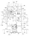
- a work machine includes a driver seat, a steering wheel disposed in front of the driver seat, a steering column that covers a steering post that supports the steering wheel, and a steering column provided below the driver seat.
- a first duct extending under the floor toward the lower portion of the steering column; and a second duct connected to the front of the first duct and rising into the steering column.
- the duct structure includes a first side duct extending from an upper portion of the steering column toward one side in a body width direction and having a first blow-out portion for blowing conditioned air into a cabin room; And a second side duct extending from the upper part of the steering column toward the other side in the machine width direction and having a second blowing part for blowing the conditioned air into the cabin.
- the second duct is provided inside the steering column. Branching into the left and right sides of the steering post, wherein the first side duct is connected to a first branch, which is one of the branches of the second duct, and the second side duct is Is connected to a second branch portion which is the other portion of the branch portion of the second duct.
- the first side duct has a first extension that extends upward
- the second side duct has a second extension that extends upward
- the first branch portion has a distal end portion bent downward and connected to the first extension portion from above
- the second branch portion has a distal end portion bent downward and has a 2 connected to the extension from above.
- the front panel of the cabin has a front window having transparency so that the front can be visually recognized, and the front window is located on one side of an upper portion of the steering column and in front of the first side duct.
- a first lower portion located on the other side of the upper portion of the steering column and in front of the second side duct;
- the floor has a floor main body having an inspection opening, and an opening / closing cover closing the inspection opening, and a portion corresponding to the inspection opening of the first duct is detachable.
- a working machine includes an air conditioner main body, and a duct structure for circulating conditioned air blown out from an outlet of the air conditioner main body, wherein the duct structure is provided at the outlet.
- One part and a second part on the other end side, and the first part is inserted and connected to one of the first member or the third member, and the second part is the first member or It is connected to the other of the third members in an abutting state.
- the second member may be inserted into one of the first member or the third member in an inclined state in which the second member moves upward from the first portion toward the second portion, and the second member may be inclined.
- the second part By moving the second part downward from the state, the second part can be connected to the other of the first member or the third member in a state of being abutted.
- the connection end of the first portion is formed in an inclined shape that shifts downward from the first portion side toward the second portion side.
- the butted end of the second portion is formed in an inclined shape that shifts downward from the second portion toward the first portion, and the first member or the first member to which the second portion is connected.
- the butting end of the third member is formed in an inclined shape corresponding to the butting end of the second part.
- the seal member includes an annular first seal member provided on an outer periphery of the second portion, and an annular second seal member provided on an outer periphery of the connection portion, and the cover plate includes the first seal member.
- the seal member and the second seal member are pressed and attached to the installation portion.
- a work machine includes a steering column supporting a steering, a brake shaft rotatably supported on the steering column around an axis extending in a machine width direction, and a side of the steering column. And a return spring returned to a position before operating the brake pedal, the return spring being formed by a torsion coil spring, It is arranged inside the steering column and provided so as to surround the periphery of the brake shaft.
- a brake arm that has an arm boss that is integrally rotatably fitted to the outer periphery of the brake shaft and that operates a master cylinder by operating the brake pedal; a bearing cylinder that supports the brake shaft; And a bush provided on a circumferential side, wherein the steering column has a first side wall and a second side wall that are arranged to face each other in the machine body width direction, and the brake shaft includes the first side wall and the second side wall.
- a bearing portion that penetrates and is coupled to the arm boss, wherein the bushing is fixed to one of the first side wall or the second side wall and surrounds the coupling portion; and the arm boss is attached to the bearing tube. A bearing portion is inserted and supported by the bush via the bush.
- the return spring is provided so as to surround the periphery of the bearing cylinder.
- the coupling portion has a protruding portion that protrudes from an end of the bearing cylinder to a side of the steering column opposite to a side on which the brake pedal is disposed.
- the brake pedal may include another brake pedal having a pedal boss coupled to the protrusion, and the pedal boss may include another bush inserted into the bearing cylinder and provided on an inner peripheral side of the bearing cylinder. Having a shaft supporting portion supported by the bush via
- the operability of the switches can be improved by providing a plurality of switches on both sides of the steering post in the body width direction in such a manner that the switches are shifted to the outside of the body as going forward. Further, a plurality of switches can be compactly arranged on the upper surface side of the steering column. Further, according to the working machine, it is possible to simplify the arrangement of the hydraulic pipeline.
- the working machine it is possible to simplify the arrangement of the hydraulic pipeline in the external hydraulic outlet structure. Further, according to the working machine, it is possible to improve the livability in the cabin room and the visibility when viewing the outside from the cabin room, as compared with the case where the brake oil tank is arranged in the cabin room.
- the duct structure so as to rise from the air conditioner main body to the inside of the steering column through the lower side of the cabin floor, the livability in the cabin is improved, The visibility when viewing the outside can be improved. Further, according to the working machine, the second member constituting the duct structure can be easily removed and attached.
- the support structure for supporting the brake pedal can be made compact.
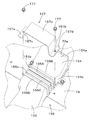
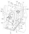
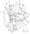
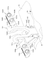
- FIG. 4 is an exploded perspective view of a mounting portion of the working tool. It is a top view of the front part of a working machine. It is the figure which looked at the quick coupler from the bottom. It is side surface sectional drawing of the connection part of a lift arm. It is the perspective view which looked at the left inner side of the quick coupler from the back side. It is the perspective view which looked at the right inside of the quick coupler from the back side. It is a perspective view of a rear body. It is the perspective view which looked at the floor frame from diagonally upper left.
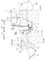
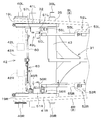
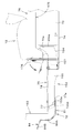
- FIG. 1 is a schematic side view showing the entire configuration of a working machine 1 according to the present embodiment.
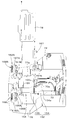
- FIG. 2 is a schematic plan view of the working machine 1.
- a wheel loader is exemplified as the work implement 1.
- the wheel loader according to the present embodiment is an articulated work machine 1, and a machine body 2 of the work machine 1 includes a front body 2 ⁇ / b> A and a rear body 2 ⁇ / b> B.
- the front body 2A is provided with a left front wheel 3L and a right front wheel 3R.
- the front wheel 3L is provided to the left of the front body 2A, and the front wheel 3R is provided to the right of the front body 2A.
- the rear body 2B is provided with a left rear wheel 4L and a right rear wheel 4R.
- the rear wheel 4L is provided on the left side of the rear body 2B, and the rear wheel 4R is provided on the right side of the rear body 2B.
- a driver's seat (seat) 13 on which an operator (driver) sits is provided on the rear body 2B.
- the driver's seat 13 is disposed between the rear wheel 4L and the rear wheel 4R, and is provided at the center of the body 2 in the body width direction K2.
- the front side (in the direction of arrow A1 in FIGS. 1 and 2) of the operator sitting on the driver's seat 13 is forward
- the rear side of the operator (in the direction of arrow A2 in FIGS. 1 and 2) is rearward
- a horizontal direction orthogonal to the front-rear direction K1 will be described as a body width direction K2 (see FIG. 2).
- the direction from the center in the width direction of the body 2 to the right or left will be described as the outside of the body.
- the outside of the fuselage means a direction that is in the fuselage width direction K2 and is separated from the center of the fuselage 2 in the width direction.
- the direction opposite to the outside of the aircraft will be described as the interior of the aircraft.
- the inside of the body is the body width direction K2 and a direction approaching the center of the body 2 in the width direction.
- a body connecting member 5 is provided at the front end side of the rear body 2B so as to be rotatable within a predetermined range around the axis in the front-rear direction K1, and the rear end side of the front body 2A is attached to the body connecting member 5. It is swingably connected in the machine width direction K2 around the vertical axis (the axis extending in the vertical direction).
- a steering cylinder 6 including a hydraulic cylinder is provided between the body connecting member 5 and the front body 2A. By expanding and contracting the steering cylinder 6, the front body 2A swings in the body width direction K2 with respect to the rear body 2B, so that the work machine 1 can turn left and right.
- a cabin 14 as a driver's seat protection device surrounding the driver's seat 13 is provided in the rear body 2B.
- a steering 15 (steering wheel) for operating the steering cylinder 6 and a control lever 16 for controlling the working device 7 are provided in the cabin 14 (hereinafter referred to as a cabin room).
- the steering 15 is arranged in front of the driver's seat 13, and the control lever 16 is arranged on the side (right side) of the driver's seat 13.
- a prime mover is mounted on the rear body 2B.
- the prime mover is a diesel engine.
- the prime mover may be a gasoline engine, an LPG engine, or an electric motor, or may be a hybrid type having an engine and an electric motor.
- the driver's seat protection device may be a canopy.
- a working device 7 front working device
- the working device 7 has a lift arm 8 supported by the front body 2A (body 2) so as to be vertically swingable.
- the lift arm 8 has a left first arm 8L and a right second arm 8R arranged at intervals in the machine body width direction K2.
- the first arm 8L is rotatably supported around an axis extending in the body width direction K2 on an upper portion of a first support frame 10L having a base end side (rear end side) erected on the left side of the front body 2A. ing. Therefore, the first arm 8L can swing up and down.
- the second arm 8R is rotatably supported on an upper portion of a second support frame 10R, the base end of which is erected on the right side of the front body 2A, about an axis extending in the body width direction K2. Therefore, the second arm 8R can also swing up and down.
- a work light (light) 33L is provided on the upper left side of the first support frame 10L.
- a work light (light) 33R is also provided on the upper right side of the second support frame 10R.
- the first arm 8L and the second arm 8R are provided at intervals in the body width direction K2 and gradually widen as the interval goes forward. As a result, the visibility of the operator seated on the driver's seat 13 in the diagonally forward left and diagonally forward directions is improved.
- the state (connected state or released state) of the first pin 40L and the second pin 40R which will be described later, it can be performed without much movement of the body. That is, it is possible to easily check the states of the first pin 40L and the second pin 40R.
- the confirmation of the front wheel 3L and the front wheel 3R can be easily performed. Thereby, the work while looking at the front wheel 3L and the front wheel 3R can be easily performed.
- the first arm 8L and the second arm 8R are connected by a connection pipe 26 provided at a middle part of the lift arm 8 in the longitudinal direction.
- the connecting pipe 26 has an elliptical cross section that is long in the longitudinal direction of the lift arm 8.
- the cross-sectional shape of the connecting pipe 26 is an oval shape (a shape in which a part of a circle is cut out flatly) in which both sides of two flat surfaces are connected by an arc.
- a lift cylinder 11L is provided between a middle part in the longitudinal direction of the first arm 8L and a middle part in the vertical direction of the first support frame 10L.
- the lift cylinder 11R is provided over a middle part in the longitudinal direction of the second arm 8R and a middle part in the vertical direction of the second support frame 10R.
- the lift cylinder 11L and the lift cylinder 11R are constituted by double-acting hydraulic cylinders. By extending and retracting the lift cylinder 11L and the lift cylinder 11R, the lift arm 8 swings up and down (the first arm 8L and the second arm 8R simultaneously).
- the working device 7 has a working tool 9 that is detachably attached to a front portion of the lift arm 8.
- the work implement 9 is provided with a bucket as a standard equipment. Instead of the bucket, a work implement (attachment) such as a pallet fork or a mania fork, or a work implement (hydraulic attachment) having a hydraulic actuator such as a sweeper, a mower, or a breaker is used. Can be attached.
- the lower rear portion of the work tool 9 is connected to and pivotally supported by the distal end (front end) of the lift arm 8.
- the work implement 1 has a work implement cylinder 12 that drives a work implement 9.
- the work implement cylinder 12 is configured by a double-acting hydraulic cylinder.
- a bracket member 27 is fixed to the connection pipe 26, and the bracket member 27 pivotally supports a vertically intermediate portion of the swing link 28.
- One end of the work implement cylinder 12 is connected to an upper portion of the swing link 28.
- the other end of the working tool cylinder 12 is pivotally supported by a bracket member 30 provided on a connecting member 29 that connects the first support frame 10L and the second support frame 10R.
- a lower portion of the swing link 28 pivotally supports a rear portion of the interlocking link 31.
- the front part of the interlocking link 31 is pivotally supported (engaged) on the upper rear part of the work implement 9.
- the swing link 28 swings and the interlocking link 31 moves back and forth.
- the work implement 9 swings up and down about the connection point with the lift arm 8.
- a first fixing plate 34 ⁇ / b> L and a second fixing plate 34 ⁇ / b> R provided at intervals in the machine body width direction K ⁇ b> 2 are provided on the back surface of the work implement (bucket) 9.
- the first fixing plate 34L and the second fixing plate 34R extend in the up-down direction.
- the first fixing plate 34L and the second fixing plate 34R have a hook portion 34a at an upper portion and an insertion hole 34b at a lower portion.
- the front wheel 3L is provided forward of the first support frame 10L and to the left of the first arm 8L.
- the front wheel 3L is located behind the left part of the work implement 9.
- the front wheel 3R is provided forward of the second support frame 10R and to the right of the second arm 8R.
- the front wheel 3 ⁇ / b> R is located behind the right part of the work implement 9.
- a control valve V1 is mounted on the front body 2A.
- the control valve V1 is a hydraulic device configured by integrating control valves for controlling hydraulic actuators such as a hydraulic cylinder and a hydraulic motor mounted on the work machine 1.
- the control valve constituting the control valve V1 is, for example, a lift control valve for controlling the lift cylinder 11, a work implement control valve for controlling the work implement cylinder 12, and a preliminary control valve 38 for controlling a hydraulic actuator mounted on the work implement 9. It is. More specifically, the preliminary control valve 38 is a control valve that controls the hydraulic actuator when the work implement 9 equipped with the hydraulic actuator is mounted.
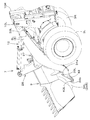
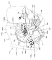
- the working device 7 has a quick coupler 32 for detachably attaching the working tool 9 to the lift arm 8.
- the quick coupler 32 includes a first engagement pin (first engagement portion) 39L, a second engagement pin (second engagement portion) 39R, a first pin (connection pin) 40L, and a second pin (connection pin) 40R.
- the first engagement pin 39L is provided on the left side of the front part of the interlocking link 31, and the second engagement pin 39R is provided on the right side of the front part of the interlocking link 31.
- a support cylinder 43 extending in the machine body width direction K2 is provided at a front portion of the interlocking link 31, and the rod member 35 is inserted through and fixed to the support cylinder 43.
- a first engagement pin 39L is formed integrally with the left end of the rod member 35.
- the first engagement pin 39L is formed smaller in diameter than the rod member 35, and is capable of engaging with the hook portion 34a of the first fixing plate 34L from below.
- the second engagement pin 39R is formed integrally with the right end of the rod member 35.
- the second engagement pin 39R is formed smaller in diameter than the rod member 35, and can be engaged with the hook portion 34a of the second fixing plate 34R from below.
- the first pin 40L is provided movably in the body width direction K2 on a bearing boss 19L provided at a front portion (front end side) of the first arm 8L.
- the first pin 40L is insertable into the insertion hole 34b of the first fixing plate 34L.
- the work implement 9 and the first arm 8L are connected by inserting the first pin 40L into the insertion hole 34b.
- the second pin 40R is provided on a bearing boss 19R provided at a front portion (front end side) of the second arm 8R so as to be movable in the machine body width direction K2.
- the second pin 40R can be inserted into the insertion hole 34b of the second fixing plate 34R.
- the working tool 9 and the second arm 8R are connected by inserting the second pin 40R into the insertion hole 34b.
- the coupler cylinder 42 is a device that drives the first pin 40L and the second pin 40R.
- the coupler cylinder 42 has a cylinder tube 42A.
- the cylinder tube 42A is arranged between the front portions of the first arm 8L and the second arm 8R (between the bearing bosses 19L and 19R) so as to extend in the machine body width direction K2.
- a first pin 40L is provided on one end side (left end side) of the cylinder tube 42A so as to be movable (movable in and out) in the machine body width direction K2. More specifically, the first pin 40L is provided so as to be movable in a direction protruding from the cylinder tube 42A (leftward) and in a direction retracting into the cylinder tube 42A (rightward).
- a first piston 42L to which the first pin 40L is connected is provided on the left side in the cylinder tube 42A.
- the first pin 40L is driven by the first piston 42L. Therefore, the first pin 40L constitutes a rod of the coupler cylinder 42. Note that the rod of the coupler cylinder 42 and the first pin 40L may be separate bodies.
- a second pin 40R is provided on the other end side (right end side) of the cylinder tube 42A so as to be movable (movable in and out) in the machine body width direction K2.
- the second pin 40R is provided so as to be movable in a direction protruding from the cylinder tube 42A (rightward) and in a direction retracting into the cylinder tube 42A (leftward).
- a second piston 42R to which the second pin 40R is connected is provided on the right side in the cylinder tube 42A.
- the second pin 40R is driven by the second piston 42R. Therefore, the second pin 40 ⁇ / b> R forms a rod of the coupler cylinder 42.
- the rod of the coupler cylinder 42 and the second pin 40R may be separate bodies.
- the coupler cylinder 42 is formed of a double-rod type hydraulic cylinder in which a pair of rods can simultaneously move out of the cylinder tube 42A.
- the first plate 41L connects the first engagement pin 39L side and the first pin 40L side. Specifically, the upper part of the first plate 41L is attached to the left part of the rod member 35. The lower part of the first plate 41L is attached to the left part of the cylinder tube 42A. The first plate 41L connects the first engagement pin 39L and the first pin 40L via the rod member 35 and the cylinder tube 42A.
- the second plate 41R connects the second engagement pin 39R side and the second pin 40R side. Specifically, the upper part of the second plate 41R is attached to the right part of the rod member 35. The lower part of the second plate 41R is attached to the right part of the cylinder tube 42A. The second plate 41R connects the second engagement pin 39R and the second pin 40R via the rod member 35 and the cylinder tube 42A.
- the first engagement pin 39L is engaged with the hook portion 34a of the first fixing plate 34L from below, and the second engagement pin 39R is connected to the second fixing plate 34R. From below.
- the lift arm 8 is moved upward from this state, the work tool 9 is lifted, and the lower side of the work tool 9 moves rearward around the first engagement pin 39L and the second engagement pin 39R.
- the work implement 9 is positioned by contacting a stopper member 48 provided on the lift arm 8.
- the first pin 40L and the second pin 40R are moved in the protruding direction in this state, the first pin 40L is inserted into the insertion hole 34b of the first fixing plate 34L, and the second pin 40R is inserted through the second fixing plate 34R. Insert through hole 34b.
- a first connection member 49L is attached to the inside of the lower portion of the first plate 41L (toward the inside of the machine).
- the first connection member 49L has a first input member 50L and a first output member 51L.
- the first hydraulic line 52L is connected to the first connection member 49L.
- the first hydraulic line 52L is routed from the preliminary control valve 38 (control valve V1) to the front of the first arm 8L along the first arm 8L.
- the first hydraulic line 52L has a first pipe 53L, a second pipe 54L, and a third pipe 55L.
- the first pipe 53L is attached to the inside of the first arm 8L (on the inside of the machine).
- the first pipe 53L is formed of a steel pipe, and is routed under the connecting pipe 26 (see FIG. 7). Thereby, the visibility in front of the operator sitting on the driver's seat 13 can be improved.
- the second pipe 54L connects the preliminary control valve 38 and the first pipe 53L.
- the third pipe 55L connects the first pipe 53L and the first input member 50L.
- the second pipe 54L and the third pipe 55L are constituted by hydraulic hoses.
- the first hydraulic pipeline 52L includes members necessary for connection of piping such as a hydraulic joint.
- the first output member 51L has a first extraction portion 56L from which hydraulic oil can be extracted.
- the first extraction portion 56L is connected to a hydraulic actuator mounted on the work implement 9 via a hydraulic hose or the like.
- the first output member 51L has a first output portion 57L.
- the first output section 57L is capable of outputting hydraulic oil.
- the first output portion 57L is connected to the head side of the first piston 42L and the second piston 42R in the coupler cylinder 42 via a connection member 60.
- the head side is the side opposite to the side where the first pin 40L and the second pin 40R are connected.
- the hydraulic oil from the first hydraulic line 52L is supplied from the first output portion 57L to the head side of the coupler cylinder 42 via the connecting member 60, so that the first piston 42L and the second piston 42R become airframes.
- the first pin 40L and the second pin 40R can be inserted through the insertion hole 34b.
- the hydraulic oil is drained from between the first piston 42L and the second piston 42R in the cylinder tube 42A via the connection member 60 and the first output portion 57L. It has become.
- a second connection member 49R is attached to the inside of the lower portion of the second plate 41R (inside the machine).
- the second connection member 49R has a second input member 50R and a second output member 51R.
- the second hydraulic line 52R is connected to the second connection member 49R.
- the second hydraulic line 52R is routed from the preliminary control valve 38 (control valve V1) to the front of the second arm 8R along the second arm 8R.
- the second hydraulic pipeline 52R has a fourth pipe 53R, a fifth pipe 54R, and a sixth pipe 55R.
- the fourth pipe 53R is attached inside the second arm 8R (on the inside of the machine).
- the fourth pipe 53R is formed of a steel pipe, and is routed under the connecting pipe 26 (see FIG.
- the fifth pipe 54R connects the preliminary control valve 38 to the fourth pipe 53R.
- the sixth pipe 55R connects the fourth pipe 53R and the second input member 50R.
- the fifth pipe 54R and the sixth pipe 55R are constituted by hydraulic hoses.
- the second hydraulic pipeline 52R also includes members necessary for connecting piping such as a hydraulic joint.
- the second output member 51R has a second extraction portion 56R that can extract hydraulic oil.
- the second extraction portion 56R is connected to a hydraulic actuator mounted on the work implement 9 via a hydraulic hose or the like.
- the second output member 51R has a second output section 57R.
- the second output unit 57R can output the hydraulic oil to the lock release valve 61.
- the lock release valve 61 is attached inside the lower part of the second plate 41R.
- the lock release valve 61 is provided near the second output member 51R.
- the lock release valve 61 is constituted by a solenoid valve (electromagnetic valve), and has a main body valve 61A for operating the coupler cylinder 42 (for supplying and discharging hydraulic oil) and a solenoid portion 61B for controlling the main body valve 61A. .
- the main valve 61A is connected to the second output portion 57R of the second output member 51R via the connection member 62.
- the main valve 61A is connected to the rod side of the first piston 42L and the second piston 42R of the coupler cylinder 42 via a connecting member 63.
- the rod side is a side to which the first pin 40L and the second pin 40R are connected. In the present embodiment, they are the one end side and the other end side of the cylinder tube 42A.
- the lock release valve 61 is operated by, for example, a switch provided on a grip of the control lever 16.
- the solenoid portion 61B is covered by a cover member 64.
- the cover member 64 is attached to the second plate 41R.
- the lock release valve 61 may be attached to the second plate 41R.
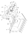
- the rear body 2B includes a body frame 71 and a floor frame 72 mounted on the body frame 71.
- the body frame 71 is movably supported by the rear wheels 4L and 4R.
- the body connecting member 5 is attached to the front of the body frame 71.
- the floor frame 72 is mounted on the body frame 71 via a mount member having an elastic material, and is supported by the body frame 71 in a vibration-proof manner.
- the floor frame 72 has a left side wall 73L and a right side wall 73R.
- a bottom wall (installation portion) 74 is provided between the lower portions of the side walls 73L and 73R.
- the floor frame 72 has a floor (step) 75 provided on the front side of the bottom wall 74.
- the bottom wall 74 is located below the floor 75. Therefore, a space is provided between the front end of the bottom wall 74 and the rear end of the floor 75. Specifically, a gap is provided between a front end side of the bottom wall 74 and an opening / closing cover 78 described later, through which a duct member for circulating conditioned air passes.
- the floor 75 has a floor main body 77 having an inspection opening 77a, and an opening / closing cover 78 for closing the inspection opening 77a.
- the floor main body 77 has a first portion 79, a second portion 80, and a third portion 81.
- the first portion 79 constitutes a left portion of the floor main body 77.
- the rear portion 79a of the first portion 79 is formed to be narrower in the body width direction K2 than the front portion 79b. More specifically, the rear portion 79a is located on the outer side (left side) of the fuselage with respect to the side wall 73L, and the front portion 79b has a portion extending forward from the rear portion 79a and a portion closer to the fuselage than the rear portion 79a. (Right side).
- the second part 80 constitutes the right part of the floor main body 77.
- the rear portion 80a of the second portion 80 is formed to be narrower in the body width direction K2 than the front portion 80b. More specifically, the rear portion 80a is located on the outer side (right side) of the fuselage with respect to the side wall 73R, and the front portion 80b has a portion extending forward from the rear portion 80a and a portion closer to the body than the rear portion 80a. (Left).
- the third portion 81 is located at the center in the machine body width direction K2, and is located between the front portion 79b of the first portion 79 and the front portion 80b of the second portion 80.
- the third part 81 connects the front part 79b and the front part 80b.
- the third portion 81 connects the rear sides of the front portion 79b and the front portion 80b.
- An opening is provided between a rear portion 79a of the first portion 79 and a rear portion 80a of the second portion 80. This opening is the inspection opening 77a. Through the inspection opening 77a, it is possible to inspect equipment and the like provided in the body frame 71.
- the third portion 81 is formed in a concave portion that is recessed downward.
- the third portion 81 includes a side wall portion 81a extending downward from a front right end of the first portion 79, a side wall portion 81b extending downward from a front left end of the second portion 80, and a side wall portion 81a. And a lower wall portion 81c connecting the lower ends of the side wall portions 81b to each other.
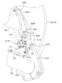
- a steering column 87 that supports the steering 15 is provided at a front portion inside the cabin. The steering column 87 is located at the center in the machine width direction K2 in the cabin.
- the steering column 87 has a column frame (frame member) 88 erected at the front of the floor frame 72 and a column cover 89 that covers the column frame 88.
- the column frame 88 is provided at the front of the floor frame 72 at the center of the body width direction K2.
- the column frame 88 is located ahead of the third portion 81.
- the column frame 88 has a first side wall 88L and a second side wall 88R arranged at intervals in the body width direction K2.
- the first side wall 88 ⁇ / b> L forms the left part of the column frame 88, and stands upright on the floor 75.
- first side wall 88L is fixed to the right end of the front part 79b of the first part 79 and to the front of the third part 81.
- the second side wall 88 ⁇ / b> R constitutes the right part of the column frame 88, and stands upright on the floor 75. Specifically, it is fixed to the left end of the front part 80 b of the second part 80 and to the front of the third part 81.
- the column frame 88 has a first connecting member 83 and a second connecting member 84.
- the first connection member 83 connects the upper portions of the rear portions of the first side wall 88L and the second side wall 88R.
- the first connecting member 83 has a mounting wall portion 83A at a central portion in the body width direction K2.
- the first connecting member 83 has one side wall portion 83L located on the left side of the mounting wall portion 83A and another side wall portion 83R located on the right side.
- the one side wall 83L and the other side wall 83R are located forward of the mounting wall 83A.
- the attachment wall 83A is connected to the one side wall 83L and the other side wall 83R.
- the first connecting member 83 protrudes forward from the left end of the one side wall 83L and is fixed to the first side wall 88L, and protrudes forward from the right end of the other side wall 83R and is fixed to the second side wall 88R. It has a fixed wall 83C.
- the second connecting member 84 connects the lower portions of the first side wall 88L and the second side wall 88R.
- the second connecting member 84 includes a rear wall 84A that rises from the front of the lower wall portion 81c of the third portion 81, and an inclined upper wall 84B that moves upward from the upper end of the rear wall 84A toward the front.
- the column cover 89 (the steering column 87) has a switch panel 99 disposed below the steering 15 on the upper surface side.
- the switch panel 99 includes a plurality of switches (first switches) that are disposed on both sides of the steering post 91 that supports the steering 15 in the body width direction K2 and that move outward from the body as it goes forward in plan view.
- the first switch group 101 includes the switches 101A to 101D).
- the column cover 89 has a first cover member 96, a second cover member 97, and a third cover member 98.
- the first cover member 96 forms the upper part of the column cover 89.
- the monitor 100 is provided on the back side of the first cover member 96.
- the front side of the first cover member 96 is open.
- the second cover member 97 is provided below the first cover member 96.
- the first cover member 96 and the second cover member 97 are located above the column frame 88, and project to the left and right from the column frame 88.
- the front side of the second cover member 97 is also open.
- the second cover member 97 has a first panel holding portion 102L that extends rearward from the first cover member 96 on the left side.
- the second portion 97b has a second panel holding portion 102R that extends rearward from the first cover member 96 on the right portion.
- the steering post 91 passes between the first panel holding portion 102L and the second panel holding portion 102R.
- the switch panel 99 includes a first switch panel 99L provided on the first panel holding unit 102L and a second switch panel 99R provided on the second panel holding unit 102R.
- the third cover member 98 has a first portion 98a, a second portion 98b, and a third portion 98c.
- the first portion 98a covers the back side of the column frame 88.
- the second portion 98b covers the lower surface side of the second cover member 97. Specifically, the second portion 98b covers the lower surface of the left portion, the lower surface of the right portion, and the lower surface of the front portion of the second cover member 97.
- the third portion 98c is located between the first panel holding portion 102L and the second panel holding portion 102R, and covers between the panel holding portions 102L and 102R.
- a boot member 103 that covers the steering post 91 is provided at the third portion 98c.
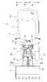
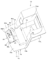
- the front side of the steering column 87 is open. As shown in FIGS. 13 and 14, the steering column 87 is disposed close to the front panel 141 of the cabin 14, and the front panel 141 covers the front side of the steering column 87. As shown in FIGS. 13 and 15, the front panel 141 includes a first front support 142L provided on the left side of the front part of the cabin 14 and a second front support 142R provided on the right side of the front part of the cabin 14. It is provided between.
- the front panel 141 has a front window 146 having transparency so that the front can be viewed.
- the front window 146 forms a middle part from the upper part of the front panel 141.
- the front window 146 has a main part 146A, a first lower part 146L, and a second lower part 146R.
- the main portion 146A is provided above the steering column 87 from the first front support 142L to the second front support 142R.
- the first lower portion 146L extends downward from the left side of the main portion 146A, and is located on one side of the upper portion of the steering column 87.
- the second lower portion 146R extends downward from the right side of the main portion 146A, and is located on the other side of the upper portion of the steering column 87.
- An opaque cover panel part 147 is provided between the first lower part 146L and the second lower part 146R. The upper front side of the steering column 87 is covered with the cover panel portion 147.
- the first switch group 101 includes a first switch 101A and a second switch 101B arranged side by side on the left side (one side) of the steering post 91, and a right side of the steering post 91 ( A third switch 101C and a fourth switch 101D arranged side by side (on the other side).
- the first switch 101A and the second switch 101B have an inclined shape that shifts leftward as going forward.
- the third switch 101C and the fourth switch 101D have an inclined shape that shifts rightward as going forward.
- the first switch 101A and the second switch 101B are provided on the first switch panel 99L, and the third switch 101C and the fourth switch 101D are provided on the second switch panel 99R.
- the first switch 101A to the fourth switch 101D are seesaw switches whose one end and the other end in the inclined direction are pressed.
- the first switch 101 ⁇ / b> A is a release switch for releasing the lock of the work implement 9.
- the first switch 101A is a double action switch with a guard.
- the operation of the lock release valve 61 cannot be performed (the operation of the lock release valve 61 becomes invalid).
- the operation of the lock release valve 61 can be performed (the operation of the lock release valve 61 becomes effective). That is, the connection between the lift arm 8 and the work tool 9 can be released by an operation intended by the operator.
- the second switch 101B is a regeneration switch that operates an exhaust gas purification device that purifies exhaust gas.
- the exhaust gas purifying device is, for example, a DPF (Diesel particulate filter).
- the third switch 101C is a light switch for turning on or off the work lights 33L and 33R.
- the fourth switch 101D is a parking switch that regulates movement during parking.
- the switch is a switch for activating or releasing a parking brake device for restricting movement of the work machine 1 during parking.
- a console 104 is provided beside the driver's seat 13 in the cabin.
- the console 104 is attached to the floor frame 72.
- a control lever 16 is provided at the front of the console 104.
- the console 104 has a switch installation section 105 provided in front of and below the control lever 16.
- the switch installation section 105 is provided with a second switch group 106 including a plurality of switches (fifth switch 106A to seventh switch 106C) arranged side by side in the machine body width direction K2.
- the fifth switch 106A to the seventh switch 106C are seesaw switches that are operated to swing back and forth.
- the second switch group 106 is an operation switch for a working system.
- the fifth switch 106A is a hold switch that keeps hydraulic oil flowing in a fixed direction to the hydraulic attachment mounted on the work implement 1, and operates to continuously maintain the operation of the hydraulic actuator mounted on the hydraulic attachment. Let it.
- the sixth switch 106 is a float switch that puts the lift arm 8 that supports the hydraulic attachment (work implement 9) so as to be able to swing up and down in a floating state.
- the seventh switch 106 is an unload switch that regulates the operation of the lift arm 8 and the hydraulic attachment, and switches the working device 7 between an operable state and an inoperable state when operated.
- a steering valve 90 for controlling the steering cylinder 6 is attached to the lower surface of the upper wall 84B.
- a steering post 91 that supports the steering 15 is attached to the upper wall 84B and the attachment wall 83A.
- the steering post 91 is provided in an inclined shape so as to pass rearward as going upward from the upper wall 84B so as to pass through the rear side of the mounting wall 83A.
- a steering shaft that transmits a steering operation to the steering valve 90 is inserted through the steering post 91.
- the steering 15 is mounted on the upper part of the steering shaft.
- the side panel 171 that forms the right side surface of the cabin 14 includes a transparent portion 171a that allows the outside to be visually recognized from between the second front support 142R of the cabin 14 and the console 104. Therefore, the outside can be seen from the cabin interior through the right side panel 171 of the cabin 14, and visibility can be improved.
- the left side panel of the cabin 14 is a door 172 for getting on and off the cabin 14 (see FIG. 1).
- the right side panel 171 is also a door that can be opened and closed. Therefore, a passage between the second front support 142R and the console 104 may be used as a boarding / alighting passage so that the vehicle can be got on and off from the right side of the cabin 14.
- the right door (side panel 171) has a transparent door window 171A that allows the outside to be viewed.
- the door window 171A includes the permeable portion 171a.
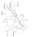
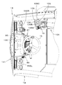
- a first brake pedal (brake pedal) 111L is disposed on the left side of the column frame 88.
- a second brake pedal (another brake pedal) 111R is disposed on the right side of the column frame 88.
- a brake shaft 112 having an axis extending in the machine body width direction K2 is provided.
- the brake shaft 112 is formed of a single rod, penetrates the upper and front portions of the first side wall 88L and the second side wall 88R, and is supported by these side walls 88L and 88R so as to be rotatable around the axis.
- the left portion of the brake shaft 112 projects leftward from the bearing boss 113 fixed to the outside of the first side wall 88L.
- a pedal boss (first pedal boss) 114L provided above the first brake pedal 111L is fixed to this protruding portion. Therefore, the first brake pedal 111L rotates integrally with the brake shaft 112.
- a step portion 115L operated by an operator is provided at a lower portion of the first brake pedal 111L. That is, the first brake pedal 111L is a suspended brake pedal.
- the right part of the brake shaft 112 projects outward from the second side wall 88R.
- a pedal boss (second pedal boss) 114R provided above the second brake pedal 111R is attached to the right portion of the brake shaft 112. Therefore, the second brake pedal 111R also rotates integrally with the brake shaft 112.
- Also provided below the second brake pedal 111R is a step portion 115R operated by the operator. That is, the second brake pedal 111R is also a suspended brake pedal.
- a coupling portion 116 is formed on the right portion of the brake shaft 112.
- This connecting portion 116 is formed by a spline. Further, the connecting portion 116 is formed up to the right end of the brake shaft 112.
- a bearing cylinder 117 that supports the brake shaft 112 is fixed to an upper portion inside the second side wall 88R.
- the bearing cylinder 117 penetrates the second side wall 88R, and protrudes from the second side wall 88R toward the inside of the machine.
- the bearing cylinder 117 has openings at both ends in the axial direction, and the brake shaft 112 passes through the bearing cylinder 117. In other words, the bush 117 surrounds the coupling portion 116.
- the bearing cylinder 117 is provided concentrically with the brake shaft 112.
- the bearing cylinder 117 has a large-diameter portion 117a that abuts on the outer surface of the second side wall 88R and is fixed by welding.
- the coupling portion 116 has a projecting portion 116a that projects outward from the right end of the large-diameter portion 117a (to the side opposite to the side on which the first brake pedal 111L is disposed). Further, the coupling portion 116 protrudes from the left end of the bearing cylinder 117.
- a brake arm 118 is disposed on the left side of the bearing cylinder 117.
- the brake arm 118 has an arm boss 119 fitted to the brake shaft 112, and an arm 120 fixed to the arm boss 119.
- the arm boss 119 is spline-coupled to the coupling part 116 and rotates integrally with the brake shaft 112. Further, the arm boss 119 has a bearing portion 119a inserted into the bearing cylinder 117.
- a bush (referred to as a first bush) 121 is provided inside the bearing cylinder 117.
- the first bush 121 is formed of a so-called DU bush, and is fitted to the outside of the bearing 119a.
- the first bush 121 is in contact with the inner peripheral surface of the bearing cylinder 117 and is in contact with the outer peripheral surface of the bearing portion 119a. Therefore, the brake shaft 112 is supported by the bearing cylinder 117 via the bearing 119 a and the first bush 121.
- one end of a connecting link 122 is pivotally supported at the rear of the arm 120, and the other end of the connecting link 122 is connected to an upper part of a piston rod 124 of a master cylinder 123. Accordingly, when the first brake pedal 111L or the second brake pedal 111R is depressed, the rear portion of the brake arm 118 swings downward with the rotation of the brake shaft 112, and the piston rod 124 is pushed through the connection link 122. . As a result, the master cylinder 123 operates and a brake device (not shown) operates.
- the arm part 120 is provided with a first contact part 120a and a second contact part 120b.
- a regulating rod 129 is provided between the first contact part 120a and the second contact part 120b.
- the regulating rod 129 is fixed to the second side wall 88R so as to protrude toward the inside of the machine.
- the master cylinder 123 is attached to a bracket member 125 fixed to the second side wall 88R.
- An attachment stay 126 is fixed to the bracket member 125, and a detection switch 127 is attached to the attachment stay 126.
- the brake arm 118 is provided with a contact member 128 that contacts the detection switch 127. When the contact member 128 contacts the detection switch 127, the positions of the first brake pedal 111L and the second brake pedal 111R before being depressed can be detected.
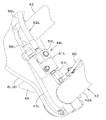
- a return spring 131 is provided inside the steering column 87 to return the brake pedals 111L and 111R to a position before operation (a set position when not operated).
- the return spring 131 is disposed on the right side between the first side wall 88L and the second side wall 88R.
- the return spring 131 is constituted by a torsion coil spring, and is provided so as to surround the brake shaft 112.
- the return spring 131 is provided so as to surround the outer circumference of the bearing cylinder 117.
- One end (left end) 131 a of the return spring 131 is hooked on a spring hook 118 a of the brake arm 118.
- the other end (right end) 131b of the return spring 131 is hooked on the regulating rod 129.
- the return spring 131 urges the first brake pedal 111L and the second brake pedal 111R in a counter-depressing direction.
- the second pedal boss 114R is spline-fitted to the projecting portion 116a of the connecting portion 116 from the right. As a result, the second pedal boss 114R rotates integrally with the brake shaft 112.
- the second pedal boss 114R has a shaft support 132 inserted into the bearing cylinder 117.
- a second bush (another bush) 133 provided on the inner peripheral side of the bearing cylinder 117 is fitted on the outer periphery of the shaft support 132.
- the second bush 133 is constituted by a so-called DU bush.
- the second bush 133 is in contact with the inner peripheral surface of the bearing cylinder 117 and is in contact with the outer peripheral surface of the shaft support 132. Therefore, the brake shaft 112 is supported by the bearing cylinder 117 via the shaft support 132 and the second bush 133.
- the removal of the second pedal boss 114R is performed by a bolt or the like screwed into the brake shaft 112.
- the second brake pedal 111R is selectively (optionally) provided to the work machine 1.
- a member having substantially the same configuration as that of the second pedal boss 114R is attached.
- a brake oil tank 134 for storing brake oil is provided inside the steering column 87.
- the brake oil tank 134 is disposed between the first side wall 88L and the second side wall 88R and on the left side. That is, it is arranged inside the first side wall 88L.
- the brake oil tank 134 is disposed below the brake shaft 112.
- the brake oil tank 134 is mounted on a mounting stay 135 fixed to the inside of the first side wall 88L by bolts.
- the brake oil tank 134 is connected to the master cylinder 123 by a connection tube 136.
- the front panel 141 has a cover panel 144 having an opening 144A at the lower part thereof to allow access to the brake oil tank 134 from the front of the cabin 14.
- the cover panel 144 has a detachable cover 144B that closes the opening 144A.
- the detachable cover 144B is fixed to the main body of the cover panel 144 by bolts 170 and is detachable. By removing the removable cover 144B, the brake oil can be supplied to the brake oil tank 134 from outside the cabin 14. Further, it is possible to perform maintenance on components and the like provided in the steering column 87.
- the return spring 131 is formed by a torsion coil spring and is provided on the outer periphery of the coupling portion 116 of the brake shaft 112, and the coupling portion 116 is supported by the bearing cylinder 117 via the arm boss 119 of the brake arm 118 and the first bush 121.
- the support structure for the brake shaft 112 can be made compact.
- a space for disposing the brake oil tank 134 in the steering column 87 can be secured.
- housing the brake oil tank 134 in the steering column 87 it is possible to reduce the number of components that obstruct the view in the cabin room, as compared with the case where the brake oil tank 134 is arranged in the cabin room. Can be improved when viewing.
- the brake oil tank 134 is disposed on the right side between the first side wall 88L and the second side wall 88R, and the master cylinder 123, the return spring 131, the bearing 117, the brake arm 118, and the like are connected to the first side wall 88L and the second side wall 88L. It may be arranged on the left side between the side walls 88R.
- a seat base 76 is mounted on the bottom wall 74, and the driver's seat 13 is mounted on the seat base 76. Further, below the driver's seat 13 (in the seat base 76), an air conditioner main body 70 is arranged.
- the air conditioner body 70 is attached to a bottom wall 74. Further, the air conditioner main body 70 is disposed at the center of the body 2 in the body width direction K2.
- the air conditioner main body 70 has a case, a blower, an evaporator, and the like housed in the case, and constitutes a main body of an air conditioner provided in the working machine 1.
- a storage box 175 is provided on the lower surface side of the upper wall of the seat base 76. The front side of the storage box 175 can be opened and closed by a lid member 176.
- the storage box 175 can store a booklet such as an instruction manual, for example.
- the working machine 1 includes a duct structure 151 that circulates conditioned air blown out from the outlet 70 a of the air conditioner main body 70.
- the outlet 70a is provided at the front of the air conditioner main body 70 and opens forward.
- the duct structure 151 has a first duct 152 and a second duct (third member) 153.
- the first duct 152 is connected to the outlet 70a and extends forward (to the lower part of the steering column 87) below the floor 75 (opening / closing cover 78) of the cabin 14. I do.
- the second duct 153 is connected to the front of the first duct 152 and rises inside the steering column 87 (see FIG. 27).
- the air conditioner main body 70, the first duct 152, and the second duct 153 are arranged at a central portion in the machine body width direction K2.
- the first duct 152 has a first member 154 having a connection port (referred to as a first connection port) 154a connected to the outlet 70a, and a first member 154 extending forward from the first member 154. And two members 155.
- the first member 154 has a connection portion 154b connected to the second member 155 at the front.
- the connection portion 154b is located below the first connection port 154a, and is attached to the bottom wall (installation portion) 74 by a bolt 177 or the like (see FIG. 26).
- a front end (butt end) 154c of the connection portion 154b is formed in an inclined shape that shifts downward as it goes forward.
- connection portion 154b is provided with a plurality of sealing materials (first sealing material 156A, first sealing material 156B).
- the first seal material 156A and the first seal material 156B are formed in an annular shape, are arranged at intervals in the front-rear direction K1, and are fitted on the outer periphery of the connection portion 154b.
- the first sealing material may be one, or three or more.
- the second member 155 is formed in a tubular shape (a tubular shape having a rectangular cross section) that is long in the front-rear direction K1. As shown in FIG. 25, the second member 155 extends forward from the connection portion 154b of the first member 154. More specifically, as shown in FIG. 23, the second member 155 extends forward from between the front end side of the bottom wall 74 and the rear end side of the floor portion 75 (opening / closing cover 78), and the lower side of the opening / closing cover 78. And extends into the third portion 81 of the floor frame 72. In other words, the second member 155 extends from the first member 154 to the lower part of the second duct 153. As shown in FIG.
- the second member 155 is located below the opening / closing cover 78, and the inspection opening 77a is long in the machine body width direction K2. That is, the inspection opening 77a is formed so as to cross the second member 155 in the machine body width direction K2 in a plan view.
- the second member 155 may be provided so as to fit in the inspection opening 77a.
- the second duct 153 has a connection port (referred to as a second connection port) 153a directed rearward at a lower portion.
- the second connection port 153a is located in the third portion 81 of the floor frame 72.
- the second member 155 is inserted into the second connection port 153a (the lower part of the second duct 153) at the front portion (one end side in the longitudinal direction) and connected thereto. Site) 155a.
- the front end (connection end) 155b of the insertion port 155a is formed in an inclined shape that shifts downward as it goes rearward. This makes it easy to connect the second member 155 in the backward inclined posture. More specifically, the second member 155 can be easily inserted into the second connection port 153a in a rearwardly inclined posture in which the rear end side is inclined above the front end side (the insertion is possible).
- the second member 155 has a connection portion (second portion) 155c at a rear portion (the other end in the longitudinal direction) connected to the connection portion 154b of the first member 154 in an abutting manner.
- the rear end (butting end) 155d of the connection portion 155c is formed in an inclined shape that shifts downward as it goes forward. Accordingly, when the rear part of the second member 155 is lowered from above and connected to the first member 154, the connection can be easily performed.
- the connecting portion 155c is provided with a plurality of sealing materials (second sealing material 156C, second sealing material 156D).
- the second sealing material 156C and the second sealing material 156D are formed in an annular shape, are arranged at intervals in the front-rear direction K1, and are fitted on the outer periphery of the connection portion 155c.
- the number of the second sealing material may be one, or three or more may be provided.
- a cover plate 157 is provided over the connection portion 154b of the first member 154 and the connection portion 155c of the second member 155.
- the cover plate 157 includes an upper wall 157a, a first side wall 157b extending downward from a left end of the upper wall 157a, and a second side wall extending downward from a right end of the upper wall 157a. 157c.
- the upper wall 157a covers above the connection portions 154b and 155c.
- the first side wall 157b covers the left side of the connection portions 154b and 155c.
- the second side wall 157c covers the left side of the connection portion 154b and the connection portion 155c.
- the upper wall 157a, the first side wall 157b, and the second side wall 157c can be in close contact with the first seal materials 156A and 156B and the second seal materials 156C and 156D.
- the first side wall 157b has a flange wall 157d extending leftward at the lower end
- the second side wall 157c has a flange wall 157e extending rightward at the lower end.
- the flange walls 157d and 157e are fixed to the bottom wall 74 by bolts 177.
- the connection portion 154b and the connection portion 155c are pressed by the cover plate 157.
- the first seal members 156A and 156B, the second seal members 156C and 156D, and the cover plate 157 ensure the sealing performance of the butted portion between the connection portion 154b and the connection portion 155c.
- the second member 155 is attached as follows. First, in a state where the opening / closing cover 78 is removed, the rear end of the second member 155 is lowered and the rear end of the connection portion 155c is inserted while the second member 155 is in the backward inclined posture and the insertion port 155a is inserted into the second connection port 153a. 155d is brought into contact with the front end 154c of the connection portion 154b. Thereafter, the cover plate 157 is attached to the bottom wall 74.
- the above operation is performed in reverse.
- the second member 155 which is a portion corresponding to the inspection opening 77a, is detachable. By removing the second member 155, there is no member that hinders the inspection, and the inspection can be easily performed. Can be.
- the mounting structure of the second member 155 is not limited to the above structure. For example, the rear part of the second member 155 is inserted into the first member 154 to be connected, and the front part of the second member 155 is connected to the first member 154.
- the two ducts 153 may be connected in a butt-like manner.
- the second duct 153 rises upward from the second connection port 153a inside the steering column 87. Further, the second duct 153 stands up behind the column frame 88 as shown in FIG. As shown in FIG. 28, the second duct 153 has a lower base portion 158 and an upper branch portion (branch portion) 159.
- the base portion 158 has a second connection port 153a and is located below the column frame 88.
- the branch portion 159 extends upward from the base portion 158 and branches in a bifurcated manner around the steering post 91. Specifically, the branch portion 159 has a first branch portion 160L located to the left of the steering post 91 and a second branch portion 160R located to the right of the steering post 91.
- the first branch portion 160L extends above the column frame 88 through the back side of the one side wall portion 83L.
- the second branch portion 160R extends above the column frame 88 through the back side of the other side wall portion 83R.
- the upper part of the first branch part 160L is located inside the upper parts of the first cover member 96 and the second cover member 97.
- the upper part of the second branch part 160R is located inside the upper parts of the first cover member 96 and the second cover member 97 (see FIG. 28).
- the first branch portion 160L has a first connection portion 161L that is bent downward at the distal end (upper portion).
- the first connection portion 161L has an opening directed downward.
- the second branch portion 160R has a second connection portion 161R that is bent downward at the tip (upper portion).
- the second connection portion 161R has an opening directed downward.
- the duct structure 151 has a first side duct 162L connected to the first branch 160L, and a second side duct 162R connected to the second branch 160R.
- the first side duct 162L is disposed to the left (one side) of the upper part of the column frame 88 (the upper part of the steering column 87).
- the first side duct 162L has a first side body 163L extending leftward from the column frame 88 side, and a first extension 164L extending upward from the right side of the first side body 163L.
- the first side body 163L has a plurality of blowout portions (first blowout portion 166A and first blowout portion 166B) on the upper rear side, and has a blowout portion (first blowout portion) on the upper front side. 3 outlets 168L).
- the first blowing section 166A and the first blowing section 166B blow the conditioned air into the cabin.
- the first lower portion 146L of the front window 146 is located in front of the first side duct 162L, and the third blowing portion 168L directs the conditioned air to the first lower portion 146L. Blow out.
- FIG. 29 the first side body 163L has a plurality of blowout portions (first blowout portion 166A and first blowout portion 166B) on the upper rear side, and has a blowout portion (first blowout portion) on the upper front side. 3 outlets 168L).
- the first blowing section 166A and the first blowing section 166B blow the conditioned air into the cabin.
- the first extension 164 ⁇ / b> L is inserted into the column cover 89 through the left portion of the second portion 98 b of the third cover member 98. As shown in FIG. 29, the first connecting portion 161L is connected to the first extending portion 164L from above. This facilitates assembly.
- first side body 163L is disposed below the second portion 98b of the third cover member 98.
- a first brake pedal 111L is disposed below the first side body 163L (see FIG. 28).
- the second side duct 162R is disposed on the upper right side (the other side) of the column frame 88.
- the second side duct 162R has a second side body 163R extending rightward from the column frame 88 side, and a second extension 164R extending upward from the left side of the second side body 163R.
- the second side body 163R has a plurality of outlets (second outlet 167A and second outlet 167B) on the upper rear side, and the outlet (first outlet) on the upper front side. 3 outlets 168R).
- the second blowing section 167A and the second blowing section 167B blow the conditioned air into the cabin.
- the second lower portion 146R of the front window 146 is located in front of the second side duct 162R, and the third blowout portion 168R directs the conditioned air to the second lower portion 146R. Blow out.
- the second extension 164 ⁇ / b> R is inserted into the column cover 89 through the right portion of the second portion 98 b of the third cover member 98.
- the second connecting portion 161R is connected to the second extending portion 164R from above. This facilitates assembly.
- the second side body 163 ⁇ / b> R is also disposed below the second portion 98 b of the third cover member 98. Further, a second brake pedal 111R is disposed below the second side duct 162R (see FIG. 28).
- the number of the first blowing sections may be one, or three or more.
- the number of the second blowing portions may be one, or may be three or more.
- a plurality of third blowout portions 168L may be provided, and a plurality of third blowout portions 168R may be provided.
- the upper part of the second duct 153 is bent downward, and the side ducts (162L, 162R) are provided with extending parts (164L, 164R) extending upward.
- the extension portion of the side duct By connecting the extension portion of the side duct, the height position of the side duct can be lowered. Thereby, the visibility from the front window 146 (the first lower portion 146L and the second lower portion 146R) can be improved.
- the duct structure 151 in the steering column 87 By arranging the duct structure 151 in the steering column 87 through the lower surface of the floor portion 75 and storing the brake oil tank 134 in the steering column 87, the left and right sides of the steering column 87 in the front part in the cabin room are provided. Therefore, it is possible to eliminate a member that hinders the field of view. As a result, the upper surfaces of the first side main body 163L and the second side main body 163R can be arranged further below the second cover member 97 of the steering column 87 arranged below the steering 15, so that The lower left and lower right portions of the window part 146 can be extended below the second cover member 97, so that the front visibility can be improved.
- the working machine 1 includes a machine body 2, a lift arm 8 mounted on the machine body 2 so as to swing up and down, a work tool 9 mounted on a front portion of the lift arm 8, and a connection between the lift arm 8 and the work tool 9.
- a quick coupler 32 having a connecting pin (a first pin 40L, a second pin 40R) to be connected, a coupler cylinder 42 for moving the connecting pin for releasing and connecting, and a coupler cylinder 42 for releasing the connection.
- An unlocking valve 61 that operates, and the unlocking valve 61 is attached to the quick coupler 32.
- the lift arm 8 includes a first arm 8L and a second arm 8R provided at intervals in the machine body width direction K2 and gradually widens as the interval goes forward. It includes a first pin 40L provided at the front of 8L and a second pin 40R provided at the front of the second arm 8R.
- the quick coupler 32 has a first engagement portion (an engagement pin 39L) that removably engages with the work implement 9 on the first arm 8L side, and is detachable from the work implement 9 on the second arm 8R side.
- the lock release valve 61 is attached to the first plate 41L or the second plate 41R.
- a first hydraulic line 52L routed along the first arm 8L from the body 2 to a front portion of the first arm 8L is connected to the first hydraulic line 52L and attached to the first plate 41L.
- the connected first connection member 63L, the second hydraulic pipeline 52R arranged along the second arm 8R from the body 2 to the front of the second arm 8R, and the second hydraulic pipeline 52R are connected.
- the first connection member 63L has a first extraction portion 56L capable of extracting hydraulic oil and a first output portion 57L capable of outputting hydraulic oil, and the second connection member 63R is capable of extracting hydraulic oil.
- One of the first output portion 57L and the second output portion 57R is connected to the head side of the coupler cylinder 42, and the other is connected to the other side. Connected to lock release valve.
- the lock release valve 61 has a main body valve 61A for operating the coupler cylinder 42 and a solenoid portion 61B for controlling the main body valve 61A.
- the operation of the lock release valve is electrically controlled. It can be easily performed and the reliability of unlocking can be increased.
- a cover member 64 that covers the solenoid portion 61B is provided. According to this configuration, the solenoid 61B can be protected.
- the working machine 1 includes a body 2 and a first arm 8L and a second arm 8L that are provided so as to extend forward from the body 2 and to be spaced apart in the body width direction K2 and gradually widen as the distance goes forward.
- the second hydraulic pipeline 52R is connected to the first hydraulic pipeline 52L, the first connecting member 63L having a first extraction portion 56L from which the hydraulic oil can be extracted, and the second hydraulic pipeline 52R is connected and operated.
- the second take-out part 56R from which oil can be taken out includes a second connecting member 63R to the.
- a connecting pipe 26 is provided for connecting the first arm 8L and the second arm 8R, and the connecting pipe 26 has an elliptical cross section that is long in the longitudinal direction of the first arm 8L and the second arm 8R.
- the first hydraulic line 52L and the second hydraulic line 52R are routed under the connecting pipe 26.
- a first pin 40L for connecting the first arm 8L and the work tool 9 a second pin 40R for connecting the second arm 8R and the work tool 9, and a first pin 40L for releasing and connecting the connection.
- the first connection member 63L supplies hydraulic oil to the head side of the coupler cylinder 42.
- the second connection member 63R has a second output portion 57R capable of outputting hydraulic oil to the lock release valve 61.
- the coupler cylinder 42 has a cylinder tube 42A extending in the body width direction K2 between the front portions of the first arm 8L and the second arm 8R, and the first pin 40L is connected to one end of the cylinder tube 42A.
- the second pin 40R is provided movably in the body width direction on the other end side of the cylinder tube 42A.
- the work machine 1 includes the body 2, a cabin 14 mounted on the body 2, a steering column 87 provided at the front of the cabin 14 in the room, and a brake oil tank 134 for storing brake oil.
- the brake oil tank 134 is provided in the steering column 87.
- a detachable cover 144B is provided for removably closing an opening 144A from which the brake oil tank 134 can be accessed from the front of the cabin 14.
- the brake oil can be supplied to the brake oil tank 134 from the front of the cabin 14.
- the detachable cover 144B forms a part of the front panel 141 of the cabin 14. According to this configuration, the structure can be simplified by sharing the members.
- the steering column 87 includes a brake pedal 111L and a return spring 131 that returns the brake pedal 111L to a position before the brake pedal 111L is operated.
- the steering column 87 has a first side wall 88L and a second side wall 88L provided at intervals in the body width direction K2.
- the brake oil tank 134 has a side wall 88R, and the brake oil tank 134 is disposed inside one of the first side wall 88L and the second side wall 88R.
- the return spring 131 is formed of a torsion coil spring and has a first side wall 88L and a second side wall 88R. The first side wall 88L or the second side wall 88R is provided so as to surround the brake shaft 112 provided thereover.
- the support structure for the brake pedal 111L can be made compact, and a space for disposing the brake oil tank 134 in the steering column 87 can be secured. Further, a master cylinder 123 operated by the brake pedal 111L is provided. The master cylinder 123 is provided between the first side wall 88L and the second side wall 88R and on the side where the return spring 131 is disposed.
- the cabin 14 includes a driver's seat 13 provided in the cabin 14 and a console 104 provided on the right side of the driver's seat 13.
- the cabin 14 is connected to a front support 142 R on the right side of the cabin 14 and the console 104.
- the work implement 1 includes a driver's seat 13, a steering 15 disposed in front of the driver's seat 13, a steering column 87 covering a steering post 91 supporting the steering 15, and an air conditioner provided below the driver's seat 13.
- the air conditioner includes a main body 70 and a duct structure 151 through which the conditioned air blown out from the air outlet 70 a of the air conditioner main body 70 flows.
- the duct structure 151 is connected to the air outlet 70 a and surrounds the cabin 13 around the driver's seat 13.
- a first duct 152 extending toward the lower part of the steering column 87 through a lower side of the floor 75 of the fourteenth, and a second duct 153 connected to the front of the first duct 152 and rising into the steering column 87.
- the duct structure 151 extends from the upper part of the steering column 87 toward one side of the body width direction K2 and has a first side duct 162L having first blowing portions 166A and 166B for blowing conditioned air into the cabin room.
- a second side duct 162R extending from the upper portion of the steering column 87 toward the other side of the body width direction K2 and having second blowing portions 167A and 167B for blowing the conditioned air into the cabin room.
- the 153 is branched into the left and right sides of the steering post 91 inside the steering column 87, and the first side duct 162L is connected to the first branch portion 160L which is one of the branch portions of the second duct 153.
- the second side duct 162R is connected to the second branch 160 which is the other part of the branch of the second duct 153. To connect to.
- the duct structure 151 can be satisfactorily distributed to the left side duct and the right side duct in the steering column 87.
- the first side duct 162L has a first extension 164L extending upward
- the second side duct 162R has a second extension 164R extending upward.
- the first branch 160L has a tip bent downward and connected to the first extension 164L from above
- the second branch 160R has a tip bent downward.
- the second extension 164R is connected from above.
- the front panel 141 of the cabin 14 has a front window 146 having transparency so that the front can be visually recognized, and the front window 146 is provided on one side of the upper part of the steering column 87 and the first side duct 162L. It has a first lower portion 146L located in the front and a second lower portion 146R located on the other side of the upper portion of the steering column 87 and in front of the second side duct 162R.
- the floor 75 has a floor main body 77 having an inspection opening 77a, and an opening / closing cover 78 for closing the inspection opening 77a.
- the first duct 152 has a detachable portion corresponding to the inspection opening 77a. According to this configuration, a member obstructing the inspection can be removed, and the inspection below the floor portion 75 can be easily performed.
- the working machine 1 includes an air conditioner main body 70 and a duct structure 151 for circulating the conditioned air blown out from the air outlet 70a of the air conditioner main body 70, and the duct structure 151 is connected to the air outlet 70a.
- It has a first member 154, a second member 155 extending from the first member 154, and a third member (second duct 153) to which the second member 155 is connected.
- It has a first portion (insertion port 155a) on one end side and a second portion (connection portion 155c) on the other end side, and the first portion is inserted into one of the first member 154 or the third member.
- the second portion is connected to the other of the first member 154 or the third member in an abutting state.
- the second member 155 is inserted into one of the first member 154 and the third member in an inclined state in which the second member 155 moves upward from the first part side toward the second part side, and the second member 155 is moved from the inclined state.
- the second portion By moving the second portion downward, the second portion can be connected to the other of the first member 154 or the third member in an abutting state.
- connection end (front end 155b) of the first portion is formed in an inclined shape that shifts downward from the first portion side toward the second portion side. According to this configuration, the insertion of one end of the second member 155 can be easily performed. Also, the butted end (rear end 155d) of the second portion is formed in an inclined shape that shifts downward from the second portion toward the first portion, and the first member to which the second portion is connected. The butting end (front end 154c) of 154 or the third member is formed in an inclined shape corresponding to the butting end of the second portion.
- the other end of the second member 155 can be easily connected.
- an installation portion (a bottom portion) that covers from the second portion to the connection portion 154b of the first member 154 or the third member connected to the second portion via a sealing material and that the second portion and the connection portion 154b are installed.
- a cover plate 157 is provided which is attached to the wall 74). According to this configuration, the other end of the second portion can be fixed while ensuring the sealing performance.
- the sealing material includes annular first sealing materials 156A and 156B provided on the outer periphery of the second portion, and annular second sealing materials 156C and 156D provided on the outer periphery of the connection portion.
- the first seal members 156A and 156B and the second seal members 156C and 156D are pressed and attached to the installation portion. According to this configuration, the sealing performance at the other end of the second member 155 can be improved.
- the cabin 14 is mounted on the body 2, the floor 75 has a floor main body 77 having an inspection opening 77 a, and an opening / closing cover 78 for closing the inspection opening 77 a, and the second member 155 is It extends forward under the floor 75. According to this configuration, by removing the second member 155, the inspection through the inspection opening 77a can be easily performed.
- the work implement 1 also includes a steering 15, a steering post 91 that supports the steering 15, and a steering column 87 that covers the steering post 91.
- the switch panels (first switch panel 99L, second switch panel 99R) are disposed below the switch panel.
- the switch panels are disposed on both sides of the steering post 91 in the body width direction K2, and are directed forward in plan view.
- the operability of the switches can be improved by providing a plurality of switches on both sides of the steering post 91 in the body width direction K2 in such a manner that the switches are shifted to the outside of the body 2 as going forward. it can. Further, a plurality of switches can be compactly arranged on the upper surface side of the steering column 87.
- the first switch group 101 includes a first switch 101A and a second switch 101B arranged side by side on one side of the steering post 91, and a third switch 101B arranged side by side on the other side of the steering post 91. It has a switch 101C and a fourth switch 101D.
- the first switch 101A to the fourth switch 101D can be arranged compactly.
- the first switch 101A to the fourth switch 101D are seesaw switches whose one end and the other end in the inclined direction are pressed. According to this configuration, the operability of the first switch 101A to the fourth switch 101D is good.
- the first switch 101A is a release switch for enabling the release operation of the connection of the work implement 9
- the second switch 101B is a regeneration switch for operating an exhaust gas purifying device for purifying exhaust gas
- the third switch 101B is a third switch for operating the exhaust gas purifying device.
- the switch 101C is a light switch for turning on or off the light
- the fourth switch 101D is a parking switch for restricting movement during parking. According to this configuration, main switches can be easily accessed.
- a driver's seat 13 disposed behind the steering wheel 15, a console 104 disposed on the side of the driver's seat 13, and a control lever 16 provided at a front portion of the console 104 are provided.
- a second switch including a switch installation section 105 provided in front of and below the control lever 16 and a plurality of switches (fifth switch 106A to seventh switch 106C) arranged in the switch installation section 105 in the machine width direction K2. Group 106.
- the second switch group includes fifth switch 106A to seventh switch 106C arranged side by side in the body width direction K2. According to this configuration, the fifth switch 106A to the seventh switch 106C can be arranged compactly.
- the fifth switch 106A to the seventh switch 106C are seesaw switches that are operated to swing back and forth. According to this configuration, the interval between the fifth switch 106A to the seventh switch 106C can be reduced, and the fifth switch 106A to the seventh switch 106C can be arranged compactly.
- the fifth switch 106A is a hold switch that keeps hydraulic oil flowing in a fixed direction to the hydraulic attachment mounted on the work machine 1, and the sixth switch 106B supports the hydraulic attachment so that it can swing up and down.
- the seventh switch 106 ⁇ / b> C is an unload switch that restricts the operation of the lift arm 8 and the hydraulic attachment.
- a cabin 14 surrounding the driver's seat 13 is provided, and the console 104 is provided on the right side of the driver's seat 13.
- the cabin 14 has a right door having a transparent door window and a right door of the cabin 14. Includes an entry / exit passage 173 provided between the front support 142R and the console 104.
- the work machine 1 includes a steering column 87 that supports the steering 15, a brake shaft 112 that is supported by the steering column 87 so as to be rotatable around an axis that extends in the machine body width direction K ⁇ b> 2, and a side of the steering column 87.
- a brake pedal 111L disposed so as to be integrally rotatable with the brake shaft 112, and a return spring 131 for returning the brake pedal 111L to a position before the brake pedal 111L is operated.
- the return spring 131 is formed by a torsion coil spring. It is arranged inside the steering column 87 and is provided so as to surround the periphery of the brake shaft 112.
- the support structure that supports the brake pedal 111L can be made compact.
- a brake arm 118 having an arm boss 119 fitted to the outer periphery of the brake shaft 112 so as to be integrally rotatable and operating the master cylinder 123 by operating the brake pedal 111L, a bearing cylinder 117 supporting the brake shaft 112, and a bearing And a bush (first bush 121) provided on the inner peripheral side of the cylinder 117.
- the steering column 87 has a first side wall 88L and a second side wall 88R opposed to each other in the body width direction K2.
- the shaft 112 has a connecting portion 116 that penetrates the first side wall 88L and the second side wall 88R and is connected to the arm boss 119, and the bearing 117 is fixed to one of the first side wall 88L or the second side wall 88R. And the arm boss 119 is inserted into the bush 117 and Through having a bearing portion 119a that is supported by the bushing 117.
- the support structure for the brake pedal 111L can be configured more compactly.
- the return spring 131 is provided so as to surround the periphery of the bearing cylinder 117. According to this configuration, the structure for supporting the brake pedal 111L can be made more compact.
- the coupling portion 116 has a protruding portion 116a that protrudes from the end of the bearing cylinder 117 to the side of the steering column 87 opposite to the side on which the brake pedal 111L is disposed.
- another brake pedal 111R can be selectively attached to the side of the steering column 87 opposite to the side on which the brake pedal 111L is arranged.
- the brake pedal 111L includes another brake pedal 111R having a pedal boss (second pedal boss) 114R coupled to the protruding portion 116a.
- the pedal boss 114R is inserted into the bearing cylinder 117 and provided on the inner peripheral side of the bearing cylinder 117.
- the shaft support 132 is supported by the bush 117 via another bush (second bush 133) provided.
- the structure for supporting the brake pedal can be made compact.
- Embodiment of this invention was described, it should be considered that Embodiment disclosed this time is an illustration and restrictive at no points.
- the scope of the present invention is defined by the terms of the claims, rather than the description above, and is intended to include any modifications within the scope and meaning equivalent to the terms of the claims.
- Reference Signs List 8 lift arm 9 work implement 13 driver's seat 15 steering 16 control lever 87 steering column 91 steering post 99L switch panel (first switch panel) 99R (2nd switch panel) 101 first switch group 101A switch (first switch) 101B switch (second switch) 101C switch (third switch) 101D switch (4th switch) 104 console 105 switch installation section 106 second switch group 106A switch (fifth switch) 106B switch (6th switch) 106C switch (7th switch) 142R Front strut 173 Boarding passage K2 Aircraft width direction
Landscapes
- Engineering & Computer Science (AREA)
- Mechanical Engineering (AREA)
- Chemical & Material Sciences (AREA)
- Combustion & Propulsion (AREA)
- Transportation (AREA)
- Mining & Mineral Resources (AREA)
- Civil Engineering (AREA)
- General Engineering & Computer Science (AREA)
- Structural Engineering (AREA)
- Lifting Devices For Agricultural Implements (AREA)
- Body Structure For Vehicles (AREA)
Abstract
La présente invention améliore l'exploitabilité d'une pluralité de commutateurs (101A-101D) disposés sur la surface supérieure d'une colonne de direction (87). Une machine de travail (1) comprend : un volant de direction (15) ; un montant de direction (91) qui supporte le volant de direction (15) ; et la colonne de direction (87) qui recouvre le montant de direction (91). La colonne de direction (87) comporte un panneau de commutation (99) qui est disposé sur la surface supérieure de la colonne de direction (87) et au-dessous du volant de direction (15). Le panneau de commutation (99) est disposé sur les deux côtés du montant de direction (91) dans une direction de largeur de machine (K2) et a un premier groupe de commutateurs (101) qui comprend la pluralité de commutateurs (101A-101D) qui sont disposés diagonalement de manière à être disposés davantage vers l'extérieur de la machine dans des zones plus proches de l'avant dans une vue en plan.
Priority Applications (2)
| Application Number | Priority Date | Filing Date | Title |
|---|---|---|---|
| EP19825061.5A EP3815983B1 (fr) | 2018-06-29 | 2019-06-05 | Machine de travail |
| US17/110,749 US12037052B2 (en) | 2018-06-29 | 2020-12-03 | Working machine |
Applications Claiming Priority (14)
| Application Number | Priority Date | Filing Date | Title |
|---|---|---|---|
| JP2018-125494 | 2018-06-29 | ||
| JP2018-125492 | 2018-06-29 | ||
| JP2018125490A JP7102262B2 (ja) | 2018-06-29 | 2018-06-29 | 作業機 |
| JP2018125492A JP6976909B2 (ja) | 2018-06-29 | 2018-06-29 | 作業機 |
| JP2018125494A JP6961544B2 (ja) | 2018-06-29 | 2018-06-29 | 作業機 |
| JP2018-125493 | 2018-06-29 | ||
| JP2018125489A JP6938442B2 (ja) | 2018-06-29 | 2018-06-29 | 作業機 |
| JP2018-125495 | 2018-06-29 | ||
| JP2018125491A JP7046738B2 (ja) | 2018-06-29 | 2018-06-29 | 作業機 |
| JP2018-125491 | 2018-06-29 | ||
| JP2018125493A JP6938443B2 (ja) | 2018-06-29 | 2018-06-29 | 作業機 |
| JP2018-125489 | 2018-06-29 | ||
| JP2018-125490 | 2018-06-29 | ||
| JP2018125495A JP6995707B2 (ja) | 2018-06-29 | 2018-06-29 | 作業機 |
Related Child Applications (1)
| Application Number | Title | Priority Date | Filing Date |
|---|---|---|---|
| US17/110,749 Continuation US12037052B2 (en) | 2018-06-29 | 2020-12-03 | Working machine |
Publications (1)
| Publication Number | Publication Date |
|---|---|
| WO2020003948A1 true WO2020003948A1 (fr) | 2020-01-02 |
Family
ID=68986571
Family Applications (1)
| Application Number | Title | Priority Date | Filing Date |
|---|---|---|---|
| PCT/JP2019/022409 Ceased WO2020003948A1 (fr) | 2018-06-29 | 2019-06-05 | Machine de travail |
Country Status (3)
| Country | Link |
|---|---|
| US (1) | US12037052B2 (fr) |
| EP (1) | EP3815983B1 (fr) |
| WO (1) | WO2020003948A1 (fr) |
Citations (12)
| Publication number | Priority date | Publication date | Assignee | Title |
|---|---|---|---|---|
| JPS5951423U (ja) * | 1982-09-28 | 1984-04-04 | いすゞ自動車株式会社 | トグルスイツチ |
| JPH07207705A (ja) | 1994-01-17 | 1995-08-08 | Kubota Corp | 作業機の操縦塔構造 |
| JPH0840223A (ja) | 1994-08-01 | 1996-02-13 | Kubota Corp | 作業車のペダル支持構造 |
| JP2005256408A (ja) * | 2004-03-11 | 2005-09-22 | Hitachi Constr Mach Co Ltd | 作業機械の前後進操作装置 |
| JP2005336771A (ja) * | 2004-05-25 | 2005-12-08 | Hitachi Constr Mach Co Ltd | 建設機械の運転操作装置 |
| JP2006083996A (ja) * | 2004-09-17 | 2006-03-30 | Yanmar Co Ltd | コンバイン |
| JP2007038821A (ja) * | 2005-08-02 | 2007-02-15 | Tokyo Magnet Oyo Seihin Kk | ハザードタイマ |
| JP2007146582A (ja) | 2005-11-30 | 2007-06-14 | Shin Caterpillar Mitsubishi Ltd | 作業車両のクイックカプラ |
| JP2013036258A (ja) | 2011-08-09 | 2013-02-21 | Kubota Corp | 作業機 |
| JP2015186939A (ja) | 2014-03-26 | 2015-10-29 | 株式会社クボタ | 作業機 |
| JP2016041565A (ja) * | 2014-08-19 | 2016-03-31 | 株式会社クボタ | 操作制御システム |
| JP2016078826A (ja) * | 2014-10-15 | 2016-05-16 | ヤンマー株式会社 | 作業車両 |
Family Cites Families (43)
| Publication number | Priority date | Publication date | Assignee | Title |
|---|---|---|---|---|
| JPS5212255Y2 (fr) * | 1972-03-03 | 1977-03-17 | ||
| DE3421602A1 (de) * | 1984-06-09 | 1985-12-12 | Iveco Magirus AG, 7900 Ulm | Schalt-lenkrad-anordnung fuer ein kraftfahrzeug |
| JPH0619148B2 (ja) | 1988-01-13 | 1994-03-16 | 株式会社クボタ | トラクタの油圧配管 |
| JPH0480434A (ja) | 1990-07-20 | 1992-03-13 | Kubota Corp | ローダ車輌の油圧継手装置 |
| JPH07207696A (ja) | 1994-01-17 | 1995-08-08 | Junji Ogawa | クイックカプラ |
| JP3164979B2 (ja) | 1994-10-06 | 2001-05-14 | 株式会社クボタ | キャビン付トラクタの空調装置 |
| DE19624463A1 (de) * | 1996-06-19 | 1998-01-02 | Fendt Xaver Gmbh & Co | Steuereinrichtung für Nutzfahrzeuge, insbesondere für landwirtschaftliche nutzbare Schlepper |
| US5924515A (en) * | 1997-03-17 | 1999-07-20 | New Holland North America, Inc. | Operator seat sliding control console |
| US6061617A (en) * | 1997-10-21 | 2000-05-09 | Case Corporation | Adaptable controller for work vehicle attachments |
| US6039141A (en) * | 1998-02-23 | 2000-03-21 | Case Corporation | Moving operator and display unit |
| JP2001199283A (ja) | 2000-01-14 | 2001-07-24 | Honda Motor Co Ltd | 小型車両 |
| US20030057065A1 (en) * | 2001-09-26 | 2003-03-27 | Hecker Steven L. | Child-safe rocker switch |
| JP2003274735A (ja) * | 2002-03-20 | 2003-09-30 | Yanmar Agricult Equip Co Ltd | コンバイン |
| US7032703B2 (en) * | 2002-06-17 | 2006-04-25 | Caterpillar Inc. | Operator control station for controlling different work machines |
| US7635045B2 (en) * | 2004-07-30 | 2009-12-22 | Caterpillar Inc. | Machine tool control console |
| JP4602733B2 (ja) * | 2004-10-12 | 2010-12-22 | ヤンマー株式会社 | 農作業機における制御装置 |
| JP4753156B2 (ja) | 2005-09-29 | 2011-08-24 | マツダ株式会社 | 自動車のペダル装置 |
| WO2008062868A1 (fr) | 2006-11-24 | 2008-05-29 | Komatsu Ltd. | Chargeuse montée sur roues |
| JP2008149942A (ja) | 2006-12-19 | 2008-07-03 | Komatsu Utility Co Ltd | ステアリングチルト機構 |
| US8240738B2 (en) * | 2009-02-04 | 2012-08-14 | Honda Motor Co., Ltd. | Vehicle switch arrangement structure |
| JP5048718B2 (ja) | 2009-06-03 | 2012-10-17 | 株式会社小松製作所 | 作業車両用運転室 |
| US8684120B2 (en) * | 2010-12-24 | 2014-04-01 | Komatsu Ltd. | Cab for construction machine |
| KR101882406B1 (ko) * | 2011-03-15 | 2018-07-26 | 가부시키가이샤 케이씨엠 | 휠 로더 |
| US8626407B2 (en) * | 2011-07-26 | 2014-01-07 | Kubota Corporation | Work vehicle |
| JP5411382B1 (ja) * | 2013-07-19 | 2014-02-12 | 株式会社小松製作所 | 作業車両 |
| US9370175B2 (en) * | 2014-02-04 | 2016-06-21 | The Toro Company | Sprayer with easily locatable operational controls, hill assist, pivotal hose reel, and agitation boost |
| JP6317202B2 (ja) * | 2014-07-08 | 2018-04-25 | 株式会社クボタ | 多機能操作具及びアームレスト操作装置 |
| JP6293597B2 (ja) | 2014-07-09 | 2018-03-14 | 三陽機器株式会社 | フロントローダ |
| JP6496180B2 (ja) * | 2014-10-24 | 2019-04-03 | ヤンマー株式会社 | トラクタ |
| WO2015088049A1 (fr) * | 2014-12-26 | 2015-06-18 | 株式会社小松製作所 | Dispositif d'affichage d'informations de statut pour engin de chantier sur roues, procédé d'affichage d'écran d'entretien pour engin de chantier sur roues et programme d'affichage d'écran d'entretien pour engin de chantier sur roues |
| US10940901B2 (en) * | 2015-07-07 | 2021-03-09 | Yanmar Power Technology Co., Ltd. | Tractor |
| JP6823500B2 (ja) * | 2017-03-03 | 2021-02-03 | 株式会社小松製作所 | 作業車両および制御方法 |
| US9859074B1 (en) * | 2017-09-03 | 2018-01-02 | Carlos M. Martinez | Locking device for rocker switch |
| KR102644630B1 (ko) * | 2017-12-18 | 2024-03-07 | 가부시끼 가이샤 구보다 | 트랙터 및 작업 차량 |
| WO2019124298A1 (fr) * | 2017-12-18 | 2019-06-27 | 株式会社クボタ | Véhicule de travail et tracteur |
| EP3663128B1 (fr) * | 2018-12-06 | 2023-10-04 | Kubota Corporation | Véhicule de travail |
| US11314274B2 (en) * | 2018-12-06 | 2022-04-26 | Kubota Corporation | Operation lever for working vehicle and working vehicle |
| EP3900506B1 (fr) * | 2018-12-20 | 2024-09-11 | Kubota Corporation | Véhicule de travail |
| CN114423277B (zh) * | 2019-09-18 | 2024-09-10 | 株式会社久保田 | 作业车辆 |
| US11541951B2 (en) * | 2019-11-08 | 2023-01-03 | Kubota Corporation | Working vehicle |
| EP4060125A4 (fr) * | 2019-11-14 | 2024-02-28 | Kubota Corporation | Engin de chantier, structure d'étanchéité pour arbre et engin de chantier comprenant ladite structure d'étanchéité |
| US12018454B2 (en) * | 2021-01-15 | 2024-06-25 | Caterpillar Inc. | Implement control console for work machines |
| GB202110408D0 (en) * | 2021-07-20 | 2021-09-01 | Agco Int Gmbh | Configurable user interface |
-
2019
- 2019-06-05 WO PCT/JP2019/022409 patent/WO2020003948A1/fr not_active Ceased
- 2019-06-05 EP EP19825061.5A patent/EP3815983B1/fr active Active
-
2020
- 2020-12-03 US US17/110,749 patent/US12037052B2/en active Active
Patent Citations (13)
| Publication number | Priority date | Publication date | Assignee | Title |
|---|---|---|---|---|
| JPS5951423U (ja) * | 1982-09-28 | 1984-04-04 | いすゞ自動車株式会社 | トグルスイツチ |
| JPH07207705A (ja) | 1994-01-17 | 1995-08-08 | Kubota Corp | 作業機の操縦塔構造 |
| JP2960847B2 (ja) | 1994-01-17 | 1999-10-12 | 株式会社クボタ | 作業機の操縦塔構造 |
| JPH0840223A (ja) | 1994-08-01 | 1996-02-13 | Kubota Corp | 作業車のペダル支持構造 |
| JP2005256408A (ja) * | 2004-03-11 | 2005-09-22 | Hitachi Constr Mach Co Ltd | 作業機械の前後進操作装置 |
| JP2005336771A (ja) * | 2004-05-25 | 2005-12-08 | Hitachi Constr Mach Co Ltd | 建設機械の運転操作装置 |
| JP2006083996A (ja) * | 2004-09-17 | 2006-03-30 | Yanmar Co Ltd | コンバイン |
| JP2007038821A (ja) * | 2005-08-02 | 2007-02-15 | Tokyo Magnet Oyo Seihin Kk | ハザードタイマ |
| JP2007146582A (ja) | 2005-11-30 | 2007-06-14 | Shin Caterpillar Mitsubishi Ltd | 作業車両のクイックカプラ |
| JP2013036258A (ja) | 2011-08-09 | 2013-02-21 | Kubota Corp | 作業機 |
| JP2015186939A (ja) | 2014-03-26 | 2015-10-29 | 株式会社クボタ | 作業機 |
| JP2016041565A (ja) * | 2014-08-19 | 2016-03-31 | 株式会社クボタ | 操作制御システム |
| JP2016078826A (ja) * | 2014-10-15 | 2016-05-16 | ヤンマー株式会社 | 作業車両 |
Non-Patent Citations (1)
| Title |
|---|
| See also references of EP3815983A4 |
Also Published As
| Publication number | Publication date |
|---|---|
| EP3815983A1 (fr) | 2021-05-05 |
| EP3815983A4 (fr) | 2022-03-09 |
| US12037052B2 (en) | 2024-07-16 |
| EP3815983B1 (fr) | 2026-04-08 |
| US20210086847A1 (en) | 2021-03-25 |
Similar Documents
| Publication | Publication Date | Title |
|---|---|---|
| US3765500A (en) | Automotive tractor unit with tiltover type cab construction | |
| KR102140360B1 (ko) | 작업 차량 | |
| JP6938442B2 (ja) | 作業機 | |
| JP7102262B2 (ja) | 作業機 | |
| CN114013519B (zh) | 一种双向操作驾驶室以及双向驾驶拖拉机 | |
| WO2020003948A1 (fr) | Machine de travail | |
| JP6938443B2 (ja) | 作業機 | |
| JP6995707B2 (ja) | 作業機 | |
| JP7046738B2 (ja) | 作業機 | |
| JP6961544B2 (ja) | 作業機 | |
| JP6976909B2 (ja) | 作業機 | |
| JP7191756B2 (ja) | 作業機 | |
| JP4451831B2 (ja) | ホイール式作業機 | |
| JP6580525B2 (ja) | 作業機 | |
| JP6580524B2 (ja) | 作業機 | |
| JP7539360B2 (ja) | 作業車 | |
| JP4808397B2 (ja) | フォークリフト | |
| JP7242381B2 (ja) | 作業機 | |
| JP7237693B2 (ja) | 作業機 | |
| JP3822078B2 (ja) | 旋回作業機 | |
| JP2007092398A (ja) | 旋回作業機 | |
| JP4471916B2 (ja) | ホイール式作業機 | |
| JP2007091042A (ja) | ホイール式作業機 | |
| JP2017227150A (ja) | 作業機 | |
| JP2005212665A (ja) | 多目的作業車 |
Legal Events
| Date | Code | Title | Description |
|---|---|---|---|
| 121 | Ep: the epo has been informed by wipo that ep was designated in this application |
Ref document number: 19825061 Country of ref document: EP Kind code of ref document: A1 |
|
| NENP | Non-entry into the national phase |
Ref country code: DE |
|
| WWE | Wipo information: entry into national phase |
Ref document number: 2019825061 Country of ref document: EP |
|
| WWG | Wipo information: grant in national office |
Ref document number: 2019825061 Country of ref document: EP |