WO2017006724A1 - Appareil de purification de gaz source et procédé de purification - Google Patents
Appareil de purification de gaz source et procédé de purification Download PDFInfo
- Publication number
- WO2017006724A1 WO2017006724A1 PCT/JP2016/067790 JP2016067790W WO2017006724A1 WO 2017006724 A1 WO2017006724 A1 WO 2017006724A1 JP 2016067790 W JP2016067790 W JP 2016067790W WO 2017006724 A1 WO2017006724 A1 WO 2017006724A1
- Authority
- WO
- WIPO (PCT)
- Prior art keywords
- source gas
- removal
- cos
- purifying
- gas
- Prior art date
- Legal status (The legal status is an assumption and is not a legal conclusion. Google has not performed a legal analysis and makes no representation as to the accuracy of the status listed.)
- Ceased
Links
Images

Classifications
-
- C—CHEMISTRY; METALLURGY
- C10—PETROLEUM, GAS OR COKE INDUSTRIES; TECHNICAL GASES CONTAINING CARBON MONOXIDE; FUELS; LUBRICANTS; PEAT
- C10L—FUELS NOT OTHERWISE PROVIDED FOR; NATURAL GAS; SYNTHETIC NATURAL GAS OBTAINED BY PROCESSES NOT COVERED BY SUBCLASSES C10G OR C10K; LIQUIFIED PETROLEUM GAS; USE OF ADDITIVES TO FUELS OR FIRES; FIRE-LIGHTERS
- C10L3/00—Gaseous fuels; Natural gas; Synthetic natural gas obtained by processes not covered by subclass C10G, C10K; Liquefied petroleum gas
- C10L3/06—Natural gas; Synthetic natural gas obtained by processes not covered by C10G, C10K3/02 or C10K3/04
- C10L3/10—Working-up natural gas or synthetic natural gas
- C10L3/101—Removal of contaminants
- C10L3/102—Removal of contaminants of acid contaminants
- C10L3/103—Sulfur containing contaminants
-
- B—PERFORMING OPERATIONS; TRANSPORTING
- B01—PHYSICAL OR CHEMICAL PROCESSES OR APPARATUS IN GENERAL
- B01D—SEPARATION
- B01D53/00—Separation of gases or vapours; Recovering vapours of volatile solvents from gases; Chemical or biological purification of waste gases, e.g. engine exhaust gases, smoke, fumes, flue gases, aerosols
- B01D53/02—Separation of gases or vapours; Recovering vapours of volatile solvents from gases; Chemical or biological purification of waste gases, e.g. engine exhaust gases, smoke, fumes, flue gases, aerosols by adsorption, e.g. preparative gas chromatography
-
- B—PERFORMING OPERATIONS; TRANSPORTING
- B01—PHYSICAL OR CHEMICAL PROCESSES OR APPARATUS IN GENERAL
- B01D—SEPARATION
- B01D53/00—Separation of gases or vapours; Recovering vapours of volatile solvents from gases; Chemical or biological purification of waste gases, e.g. engine exhaust gases, smoke, fumes, flue gases, aerosols
- B01D53/02—Separation of gases or vapours; Recovering vapours of volatile solvents from gases; Chemical or biological purification of waste gases, e.g. engine exhaust gases, smoke, fumes, flue gases, aerosols by adsorption, e.g. preparative gas chromatography
- B01D53/04—Separation of gases or vapours; Recovering vapours of volatile solvents from gases; Chemical or biological purification of waste gases, e.g. engine exhaust gases, smoke, fumes, flue gases, aerosols by adsorption, e.g. preparative gas chromatography with stationary adsorbents
-
- B—PERFORMING OPERATIONS; TRANSPORTING
- B01—PHYSICAL OR CHEMICAL PROCESSES OR APPARATUS IN GENERAL
- B01D—SEPARATION
- B01D53/00—Separation of gases or vapours; Recovering vapours of volatile solvents from gases; Chemical or biological purification of waste gases, e.g. engine exhaust gases, smoke, fumes, flue gases, aerosols
- B01D53/14—Separation of gases or vapours; Recovering vapours of volatile solvents from gases; Chemical or biological purification of waste gases, e.g. engine exhaust gases, smoke, fumes, flue gases, aerosols by absorption
- B01D53/1425—Regeneration of liquid absorbents
-
- B—PERFORMING OPERATIONS; TRANSPORTING
- B01—PHYSICAL OR CHEMICAL PROCESSES OR APPARATUS IN GENERAL
- B01D—SEPARATION
- B01D53/00—Separation of gases or vapours; Recovering vapours of volatile solvents from gases; Chemical or biological purification of waste gases, e.g. engine exhaust gases, smoke, fumes, flue gases, aerosols
- B01D53/14—Separation of gases or vapours; Recovering vapours of volatile solvents from gases; Chemical or biological purification of waste gases, e.g. engine exhaust gases, smoke, fumes, flue gases, aerosols by absorption
- B01D53/1456—Removing acid components
- B01D53/1462—Removing mixtures of hydrogen sulfide and carbon dioxide
-
- B—PERFORMING OPERATIONS; TRANSPORTING
- B01—PHYSICAL OR CHEMICAL PROCESSES OR APPARATUS IN GENERAL
- B01D—SEPARATION
- B01D53/00—Separation of gases or vapours; Recovering vapours of volatile solvents from gases; Chemical or biological purification of waste gases, e.g. engine exhaust gases, smoke, fumes, flue gases, aerosols
- B01D53/14—Separation of gases or vapours; Recovering vapours of volatile solvents from gases; Chemical or biological purification of waste gases, e.g. engine exhaust gases, smoke, fumes, flue gases, aerosols by absorption
- B01D53/1456—Removing acid components
- B01D53/1468—Removing hydrogen sulfide
-
- B—PERFORMING OPERATIONS; TRANSPORTING
- B01—PHYSICAL OR CHEMICAL PROCESSES OR APPARATUS IN GENERAL
- B01D—SEPARATION
- B01D53/00—Separation of gases or vapours; Recovering vapours of volatile solvents from gases; Chemical or biological purification of waste gases, e.g. engine exhaust gases, smoke, fumes, flue gases, aerosols
- B01D53/14—Separation of gases or vapours; Recovering vapours of volatile solvents from gases; Chemical or biological purification of waste gases, e.g. engine exhaust gases, smoke, fumes, flue gases, aerosols by absorption
- B01D53/1493—Selection of liquid materials for use as absorbents
-
- B—PERFORMING OPERATIONS; TRANSPORTING
- B01—PHYSICAL OR CHEMICAL PROCESSES OR APPARATUS IN GENERAL
- B01D—SEPARATION
- B01D53/00—Separation of gases or vapours; Recovering vapours of volatile solvents from gases; Chemical or biological purification of waste gases, e.g. engine exhaust gases, smoke, fumes, flue gases, aerosols
- B01D53/22—Separation of gases or vapours; Recovering vapours of volatile solvents from gases; Chemical or biological purification of waste gases, e.g. engine exhaust gases, smoke, fumes, flue gases, aerosols by diffusion
- B01D53/229—Integrated processes (Diffusion and at least one other process, e.g. adsorption, absorption)
-
- B—PERFORMING OPERATIONS; TRANSPORTING
- B01—PHYSICAL OR CHEMICAL PROCESSES OR APPARATUS IN GENERAL
- B01D—SEPARATION
- B01D53/00—Separation of gases or vapours; Recovering vapours of volatile solvents from gases; Chemical or biological purification of waste gases, e.g. engine exhaust gases, smoke, fumes, flue gases, aerosols
- B01D53/34—Chemical or biological purification of waste gases
- B01D53/46—Removing components of defined structure
- B01D53/48—Sulfur compounds
- B01D53/50—Sulfur oxides
- B01D53/501—Sulfur oxides by treating the gases with a solution or a suspension of an alkali or earth-alkali or ammonium compound
-
- B—PERFORMING OPERATIONS; TRANSPORTING
- B01—PHYSICAL OR CHEMICAL PROCESSES OR APPARATUS IN GENERAL
- B01D—SEPARATION
- B01D53/00—Separation of gases or vapours; Recovering vapours of volatile solvents from gases; Chemical or biological purification of waste gases, e.g. engine exhaust gases, smoke, fumes, flue gases, aerosols
- B01D53/34—Chemical or biological purification of waste gases
- B01D53/74—General processes for purification of waste gases; Apparatus or devices specially adapted therefor
- B01D53/86—Catalytic processes
-
- B—PERFORMING OPERATIONS; TRANSPORTING
- B01—PHYSICAL OR CHEMICAL PROCESSES OR APPARATUS IN GENERAL
- B01D—SEPARATION
- B01D53/00—Separation of gases or vapours; Recovering vapours of volatile solvents from gases; Chemical or biological purification of waste gases, e.g. engine exhaust gases, smoke, fumes, flue gases, aerosols
- B01D53/34—Chemical or biological purification of waste gases
- B01D53/74—General processes for purification of waste gases; Apparatus or devices specially adapted therefor
- B01D53/86—Catalytic processes
- B01D53/8603—Removing sulfur compounds
- B01D53/8606—Removing sulfur compounds only one sulfur compound other than sulfur oxides or hydrogen sulfide
-
- C—CHEMISTRY; METALLURGY
- C10—PETROLEUM, GAS OR COKE INDUSTRIES; TECHNICAL GASES CONTAINING CARBON MONOXIDE; FUELS; LUBRICANTS; PEAT
- C10K—PURIFYING OR MODIFYING THE CHEMICAL COMPOSITION OF COMBUSTIBLE GASES CONTAINING CARBON MONOXIDE
- C10K1/00—Purifying combustible gases containing carbon monoxide
- C10K1/002—Removal of contaminants
- C10K1/003—Removal of contaminants of acid contaminants, e.g. acid gas removal
- C10K1/004—Sulfur containing contaminants, e.g. hydrogen sulfide
-
- C—CHEMISTRY; METALLURGY
- C10—PETROLEUM, GAS OR COKE INDUSTRIES; TECHNICAL GASES CONTAINING CARBON MONOXIDE; FUELS; LUBRICANTS; PEAT
- C10K—PURIFYING OR MODIFYING THE CHEMICAL COMPOSITION OF COMBUSTIBLE GASES CONTAINING CARBON MONOXIDE
- C10K1/00—Purifying combustible gases containing carbon monoxide
- C10K1/08—Purifying combustible gases containing carbon monoxide by washing with liquids; Reviving the used wash liquors
-
- C—CHEMISTRY; METALLURGY
- C10—PETROLEUM, GAS OR COKE INDUSTRIES; TECHNICAL GASES CONTAINING CARBON MONOXIDE; FUELS; LUBRICANTS; PEAT
- C10K—PURIFYING OR MODIFYING THE CHEMICAL COMPOSITION OF COMBUSTIBLE GASES CONTAINING CARBON MONOXIDE
- C10K1/00—Purifying combustible gases containing carbon monoxide
- C10K1/32—Purifying combustible gases containing carbon monoxide with selectively adsorptive solids, e.g. active carbon
-
- C—CHEMISTRY; METALLURGY
- C10—PETROLEUM, GAS OR COKE INDUSTRIES; TECHNICAL GASES CONTAINING CARBON MONOXIDE; FUELS; LUBRICANTS; PEAT
- C10K—PURIFYING OR MODIFYING THE CHEMICAL COMPOSITION OF COMBUSTIBLE GASES CONTAINING CARBON MONOXIDE
- C10K1/00—Purifying combustible gases containing carbon monoxide
- C10K1/34—Purifying combustible gases containing carbon monoxide by catalytic conversion of impurities to more readily removable materials
-
- C—CHEMISTRY; METALLURGY
- C10—PETROLEUM, GAS OR COKE INDUSTRIES; TECHNICAL GASES CONTAINING CARBON MONOXIDE; FUELS; LUBRICANTS; PEAT
- C10L—FUELS NOT OTHERWISE PROVIDED FOR; NATURAL GAS; SYNTHETIC NATURAL GAS OBTAINED BY PROCESSES NOT COVERED BY SUBCLASSES C10G OR C10K; LIQUIFIED PETROLEUM GAS; USE OF ADDITIVES TO FUELS OR FIRES; FIRE-LIGHTERS
- C10L3/00—Gaseous fuels; Natural gas; Synthetic natural gas obtained by processes not covered by subclass C10G, C10K; Liquefied petroleum gas
- C10L3/06—Natural gas; Synthetic natural gas obtained by processes not covered by C10G, C10K3/02 or C10K3/04
- C10L3/10—Working-up natural gas or synthetic natural gas
- C10L3/101—Removal of contaminants
-
- B—PERFORMING OPERATIONS; TRANSPORTING
- B01—PHYSICAL OR CHEMICAL PROCESSES OR APPARATUS IN GENERAL
- B01D—SEPARATION
- B01D2252/00—Absorbents, i.e. solvents and liquid materials for gas absorption
- B01D2252/20—Organic absorbents
- B01D2252/204—Amines
-
- B—PERFORMING OPERATIONS; TRANSPORTING
- B01—PHYSICAL OR CHEMICAL PROCESSES OR APPARATUS IN GENERAL
- B01D—SEPARATION
- B01D2252/00—Absorbents, i.e. solvents and liquid materials for gas absorption
- B01D2252/20—Organic absorbents
- B01D2252/204—Amines
- B01D2252/20478—Alkanolamines
- B01D2252/20489—Alkanolamines with two or more hydroxyl groups
-
- B—PERFORMING OPERATIONS; TRANSPORTING
- B01—PHYSICAL OR CHEMICAL PROCESSES OR APPARATUS IN GENERAL
- B01D—SEPARATION
- B01D2253/00—Adsorbents used in seperation treatment of gases and vapours
- B01D2253/10—Inorganic adsorbents
- B01D2253/106—Silica or silicates
- B01D2253/108—Zeolites
-
- B—PERFORMING OPERATIONS; TRANSPORTING
- B01—PHYSICAL OR CHEMICAL PROCESSES OR APPARATUS IN GENERAL
- B01D—SEPARATION
- B01D2253/00—Adsorbents used in seperation treatment of gases and vapours
- B01D2253/10—Inorganic adsorbents
- B01D2253/112—Metals or metal compounds not provided for in B01D2253/104 or B01D2253/106
- B01D2253/1124—Metal oxides
-
- B—PERFORMING OPERATIONS; TRANSPORTING
- B01—PHYSICAL OR CHEMICAL PROCESSES OR APPARATUS IN GENERAL
- B01D—SEPARATION
- B01D2256/00—Main component in the product gas stream after treatment
- B01D2256/24—Hydrocarbons
-
- B—PERFORMING OPERATIONS; TRANSPORTING
- B01—PHYSICAL OR CHEMICAL PROCESSES OR APPARATUS IN GENERAL
- B01D—SEPARATION
- B01D2257/00—Components to be removed
- B01D2257/30—Sulfur compounds
- B01D2257/302—Sulfur oxides
-
- B—PERFORMING OPERATIONS; TRANSPORTING
- B01—PHYSICAL OR CHEMICAL PROCESSES OR APPARATUS IN GENERAL
- B01D—SEPARATION
- B01D2257/00—Components to be removed
- B01D2257/30—Sulfur compounds
- B01D2257/304—Hydrogen sulfide
-
- B—PERFORMING OPERATIONS; TRANSPORTING
- B01—PHYSICAL OR CHEMICAL PROCESSES OR APPARATUS IN GENERAL
- B01D—SEPARATION
- B01D2257/00—Components to be removed
- B01D2257/30—Sulfur compounds
- B01D2257/306—Organic sulfur compounds, e.g. mercaptans
-
- B—PERFORMING OPERATIONS; TRANSPORTING
- B01—PHYSICAL OR CHEMICAL PROCESSES OR APPARATUS IN GENERAL
- B01D—SEPARATION
- B01D2257/00—Components to be removed
- B01D2257/30—Sulfur compounds
- B01D2257/308—Carbonoxysulfide COS
-
- B—PERFORMING OPERATIONS; TRANSPORTING
- B01—PHYSICAL OR CHEMICAL PROCESSES OR APPARATUS IN GENERAL
- B01D—SEPARATION
- B01D2257/00—Components to be removed
- B01D2257/50—Carbon oxides
- B01D2257/504—Carbon dioxide
-
- B—PERFORMING OPERATIONS; TRANSPORTING
- B01—PHYSICAL OR CHEMICAL PROCESSES OR APPARATUS IN GENERAL
- B01D—SEPARATION
- B01D2257/00—Components to be removed
- B01D2257/60—Heavy metals or heavy metal compounds
- B01D2257/602—Mercury or mercury compounds
-
- B—PERFORMING OPERATIONS; TRANSPORTING
- B01—PHYSICAL OR CHEMICAL PROCESSES OR APPARATUS IN GENERAL
- B01D—SEPARATION
- B01D2257/00—Components to be removed
- B01D2257/80—Water
-
- B—PERFORMING OPERATIONS; TRANSPORTING
- B01—PHYSICAL OR CHEMICAL PROCESSES OR APPARATUS IN GENERAL
- B01D—SEPARATION
- B01D2259/00—Type of treatment
- B01D2259/40—Further details for adsorption processes and devices
- B01D2259/40083—Regeneration of adsorbents in processes other than pressure or temperature swing adsorption
- B01D2259/40088—Regeneration of adsorbents in processes other than pressure or temperature swing adsorption by heating
-
- C—CHEMISTRY; METALLURGY
- C10—PETROLEUM, GAS OR COKE INDUSTRIES; TECHNICAL GASES CONTAINING CARBON MONOXIDE; FUELS; LUBRICANTS; PEAT
- C10L—FUELS NOT OTHERWISE PROVIDED FOR; NATURAL GAS; SYNTHETIC NATURAL GAS OBTAINED BY PROCESSES NOT COVERED BY SUBCLASSES C10G OR C10K; LIQUIFIED PETROLEUM GAS; USE OF ADDITIVES TO FUELS OR FIRES; FIRE-LIGHTERS
- C10L2290/00—Fuel preparation or upgrading, processes or apparatus therefore, comprising specific process steps or apparatus units
- C10L2290/54—Specific separation steps for separating fractions, components or impurities during preparation or upgrading of a fuel
- C10L2290/541—Absorption of impurities during preparation or upgrading of a fuel
-
- C—CHEMISTRY; METALLURGY
- C10—PETROLEUM, GAS OR COKE INDUSTRIES; TECHNICAL GASES CONTAINING CARBON MONOXIDE; FUELS; LUBRICANTS; PEAT
- C10L—FUELS NOT OTHERWISE PROVIDED FOR; NATURAL GAS; SYNTHETIC NATURAL GAS OBTAINED BY PROCESSES NOT COVERED BY SUBCLASSES C10G OR C10K; LIQUIFIED PETROLEUM GAS; USE OF ADDITIVES TO FUELS OR FIRES; FIRE-LIGHTERS
- C10L2290/00—Fuel preparation or upgrading, processes or apparatus therefore, comprising specific process steps or apparatus units
- C10L2290/54—Specific separation steps for separating fractions, components or impurities during preparation or upgrading of a fuel
- C10L2290/542—Adsorption of impurities during preparation or upgrading of a fuel
-
- C—CHEMISTRY; METALLURGY
- C10—PETROLEUM, GAS OR COKE INDUSTRIES; TECHNICAL GASES CONTAINING CARBON MONOXIDE; FUELS; LUBRICANTS; PEAT
- C10L—FUELS NOT OTHERWISE PROVIDED FOR; NATURAL GAS; SYNTHETIC NATURAL GAS OBTAINED BY PROCESSES NOT COVERED BY SUBCLASSES C10G OR C10K; LIQUIFIED PETROLEUM GAS; USE OF ADDITIVES TO FUELS OR FIRES; FIRE-LIGHTERS
- C10L2290/00—Fuel preparation or upgrading, processes or apparatus therefore, comprising specific process steps or apparatus units
- C10L2290/54—Specific separation steps for separating fractions, components or impurities during preparation or upgrading of a fuel
- C10L2290/548—Membrane- or permeation-treatment for separating fractions, components or impurities during preparation or upgrading of a fuel
-
- Y—GENERAL TAGGING OF NEW TECHNOLOGICAL DEVELOPMENTS; GENERAL TAGGING OF CROSS-SECTIONAL TECHNOLOGIES SPANNING OVER SEVERAL SECTIONS OF THE IPC; TECHNICAL SUBJECTS COVERED BY FORMER USPC CROSS-REFERENCE ART COLLECTIONS [XRACs] AND DIGESTS
- Y02—TECHNOLOGIES OR APPLICATIONS FOR MITIGATION OR ADAPTATION AGAINST CLIMATE CHANGE
- Y02C—CAPTURE, STORAGE, SEQUESTRATION OR DISPOSAL OF GREENHOUSE GASES [GHG]
- Y02C20/00—Capture or disposal of greenhouse gases
- Y02C20/40—Capture or disposal of greenhouse gases of CO2
-
- Y—GENERAL TAGGING OF NEW TECHNOLOGICAL DEVELOPMENTS; GENERAL TAGGING OF CROSS-SECTIONAL TECHNOLOGIES SPANNING OVER SEVERAL SECTIONS OF THE IPC; TECHNICAL SUBJECTS COVERED BY FORMER USPC CROSS-REFERENCE ART COLLECTIONS [XRACs] AND DIGESTS
- Y02—TECHNOLOGIES OR APPLICATIONS FOR MITIGATION OR ADAPTATION AGAINST CLIMATE CHANGE
- Y02P—CLIMATE CHANGE MITIGATION TECHNOLOGIES IN THE PRODUCTION OR PROCESSING OF GOODS
- Y02P20/00—Technologies relating to chemical industry
- Y02P20/151—Reduction of greenhouse gas [GHG] emissions, e.g. CO2
Definitions
- the present invention relates to a source gas purification apparatus and a purification method.
- untreated natural gas includes, in addition to hydrocarbons (HC) such as methane, CO 2 , H 2 S (hydrogen sulfide), COS (carbonyl sulfide), RSH (mercaptans), H 2 O, Hg ( Contains impurities such as mercury).
- HC hydrocarbons
- methane CO 2
- H 2 S hydrogen sulfide
- COS carbonyl sulfide
- RSH mercaptans
- H 2 O Hg
- Hg Contains impurities such as mercury
- Patent Document 1 As one of the techniques for solving the above problems, a method according to Patent Document 1 is known which employs a guard bed for hydrolyzing COS to H 2 S prior to chemical absorption of a source gas. .
- the metal oxide material for decomposing COS since the metal oxide material for decomposing COS is used in combination with the Hg adsorbent, there is a possibility that the resolution of the COS by the metal oxide material may be deteriorated early.
- H 2 S is contained in a large amount in the source gas, there is a fear that COS can not be converted to H 2 S.
- Patent Document 1 describes that gas-liquid separation by cooling is effective with respect to the RSH treatment method.
- the present invention has been made in view of the above circumstances, and it is possible to provide a source gas purification apparatus and a purification method in which the burden of cost, labor and the like in the process is reduced and the system is simplified. With the goal.
- the present invention in order to achieve the object, an apparatus for purifying the raw material gas, and at least a hydrocarbon, and H 2 S, from a raw material gas containing sulfur compounds other than H 2 S, the H 2 S a first H 2 S removal device for removing the conversion device of the sulfur compounds to convert the sulfur compounds other than the H 2 S in H 2 S, the second H 2 S to remove the conversion has been H 2 S And a removing device.
- the sulfur compounds other than H 2 S can be made COS and RSH.
- the conversion device of the sulfur compound can be configured as a COS-RSH conversion catalyst device.
- the first H 2 S removal apparatus can be configured as a chemical absorption apparatus.
- the second H 2 S removal apparatus can be configured as an adsorption / desorption apparatus using an adsorbent.
- the adsorbent is preferably a molecular sieve or zinc oxide.
- the raw material gas purification apparatus according to the present invention may further include, in another embodiment, an H 2 S combustion apparatus and a limestone-type desulfurization apparatus for treating an exhaust gas from the H 2 S combustion apparatus.
- the first H 2 S removal device H 2 S separation membrane, or the H 2 S separation apparatus having a H 2 S adsorbent can be configured as a chemical absorption device.
- the second H 2 S removal device can be configured as an adsorption / desorption device.
- a mercury removal apparatus can be further provided immediately before the conversion apparatus of the sulfur compound.
- the present invention in another aspect, is a method of purifying a feed gas, the method of purifying the feed gas comprising at least a hydrocarbon, H 2 S, and a sulfur compound other than H 2 S. a first H 2 S removal step of removing H 2 S, and conversion processes of the sulfur compounds other than the H 2 S sulfur compound which is converted to a H 2 S, the second to remove the conversion has been H 2 S And an H 2 S removing step.
- the sulfur compound other than H 2 S can be made COS and RSH.
- the conversion step of the sulfur compound can be carried out as a COS-RSH conversion catalyst step.
- the method for purifying a source gas according to the present invention can implement the first H 2 S removing step as a chemical absorption step in another embodiment.
- the second H 2 S removing step can be carried out as a removing step by an adsorption / desorption device configured using an adsorbent.
- the adsorbent is preferably a molecular sieve or zinc oxide.
- the purification method of the raw material gas according to the present invention may further include, in another embodiment, a H 2 S combustion process and a limestone-type desulfurization process for treating an exhaust gas from the H 2 S combustion process.
- the second H 2 S removing step can be performed as a chemical absorption step.
- Purification method for raw material gas in accordance with the present invention use in other embodiments, the first H 2 S removal process to H 2 S separation membrane, or the H 2 S separation apparatus having a H 2 S adsorbent
- the second H 2 S removal step can be carried out as an adsorption step using an adsorption / desorption device.
- a mercury removal step can be further provided immediately before the conversion step of the sulfur compound.
- the burden of cost, labor, etc. in the process is reduced, and the system is simplified.
- a purification apparatus, and a purification method are provided.
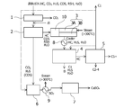
- FIG. 1 conceptually shows a first embodiment of a raw material gas purification apparatus according to the present invention.
- the raw material gas purification apparatus according to the present embodiment is provided with a CO 2 separation device 1, a chemical absorption device 2, a sulfur compound conversion catalyst device 3, and an adsorption / desorption device 4 as main components.
- natural gas containing sulfur compounds other than CO 2 , H 2 S, H 2 S (mainly COS and RSH), and H 2 O as impurities is treated. It is used as the target source gas.
- the raw material gas to be treated according to the present invention is not limited to natural gas, and, for example, coal gasification gas, synthesis gas, coke oven gas, petroleum gas (accompanying gas associated with crude oil production, etc.), etc. can include, but is not limited thereto, as long as the gas containing acid gases such as H 2 S, the application of interest. That is, the object of the present embodiment and other embodiments of the present invention is not limited to natural gas.
- the CO 2 separation device 1 is provided as one form of the CO 2 removal device.
- the CO 2 separation device 1 is a device that removes the CO 2 and the other gas components by using the difference in mobility of the CO 2 and the other gas components in the film.
- a CO 2 separation membrane is mainly used, and more specifically, a known one composed of a polymer material such as cellulose, polysulfone, polyimide, an inorganic material such as zeolite, and carbon It can be adopted.
- the chemical absorption device 2 is provided as one form of a first H 2 S removal device. In addition to the removal of H 2 S, the chemical absorption device 2 also removes remaining CO 2 that has not been completely removed by the CO 2 separation device 1.
- the remaining CO 2 and H 2 S are absorbed and removed by bringing an amine absorbing solution containing an amine compound into contact with the raw material gas. After such absorption and removal, CO 2 and H 2 S are dissipated by heating the amine absorbing solution, and the amine absorbing solution is regenerated.
- An amine is a compound that exhibits weak basicity , and has the characteristics of adsorbing an acidic substance such as CO 2 and H 2 S and emitting it by applying heat. This feature can be exploited and used as an acid gas absorbent.
- an absorbing solution based on MDEA N-methyldiethanolamine
- the raw material gas from which CO 2 and H 2 S have been removed is sent to the sulfur compound conversion catalyst device 3.
- the raw material gas from which CO 2 and H 2 S have been removed contains, in addition to hydrocarbons such as methane, COS, RSH and H 2 O.
- the sulfur compound conversion catalyst device 3 is provided as one form of a conversion device of a sulfur compound.
- the sulfur compound conversion catalyst device 3 according to the present embodiment is configured as a COS / RSH conversion catalyst device provided with a forward COS conversion catalyst device 3A and a downstream RSH conversion catalyst device 3B.
- COS conversion catalyst device 3A COS is converted to H 2 S
- RSH conversion catalyst device 3B RSH is converted to H 2 S.
- COS conversion catalyst used in the COS conversion catalyst device 3A using Al 2 O 3 and / or TiO 2 as a support, calcium, magnesium, strontium, zinc, iron, copper, manganese, chromium, barium, nickel, ruthenium, cobalt And a catalyst containing, as a main component, at least one metal selected from the group consisting of molybdenum.
- the RSH conversion catalyst used in the RSH conversion catalyst device 3B include at least one solid acid catalyst selected from silica-alumina, zeolite and the like.
- the COS conversion catalyst device 3A and the RSH conversion catalyst device 3B are arranged in tandem so that the smaller one of COS and RSH is to be treated first. Capped, the resulting H 2 S increases, generation system becomes large abundance of H 2 S, because the reaction in the direction that produces a chemical equilibrium on H 2 S becomes difficult to proceed. By processing the one with the smaller proportion first, it is possible to facilitate later conversion of the conversion target with less H 2 S. In general natural gas, since RSH has a larger presence ratio, it is preferable to dispose the COS conversion catalyst device 3A first and convert COS first.
- the COS conversion catalyst device 3A and the RSH conversion catalyst device 3B are integrally configured in the same reaction vessel, and at least one member belonging to Group V, Group VI, and Group VII as the inorganic oxide support It is also possible to carry out a catalyst on which the metal of the present invention is supported, using, for example, a catalyst such as C-Mo / alumina etc., in the form of simultaneously promoting the conversion of both COS and RSH. Furthermore, only one of the COS conversion catalyst device 3A and the RSH conversion catalyst device 3B can be operated according to the properties of the raw material gas to be treated. Alternatively, only one of them may be provided.
- the adsorption / desorption device 4 is provided as one form of a second H 2 S removal device.
- the material constituting the adsorption / desorption device 4 can be an adsorbent such as molecular sieve or zinc oxide employing a known material such as artificial zeolite.
- the adsorption / desorption device 4 adsorbs and removes H 2 S and H 2 O from the sulfur compound conversion catalyst device 3.
- the adsorption / desorption device 4 is regenerated by desorbing H 2 S and H 2 O by heating and depressurization.
- the source gas purification apparatus further includes, as other components, an NGL recovery apparatus 5, an H 2 S combustion apparatus 6, and a lime plaster type desulfurization apparatus 7.
- the NGL recovery unit 5 is a hydrocarbon obtained by removing H 2 S and H 2 O by the adsorption / desorption unit 4 as C1 hydrocarbon (methane), C2-4 hydrocarbon (hydrocarbon having 2 to 4 carbon atoms) And C5 + (hydrocarbon having 5 or more carbon atoms).
- the NGL recovery device 5 separates hydrocarbons by a known method such as cryogenic separation process using a turbo expander.
- the H 2 S combustion device 6 is a device for burning and processing H 2 S and COS, and can be configured by a known combustion device such as a combustion burner.
- the limestone type desulfurization apparatus 7 is an apparatus for recovering SO 2 (sulfurous acid gas) generated by burning H 2 S and COS as gypsum (CaSO 4 .2H 2 O).
- SO 2 sulfurous acid gas
- gypsum CaSO 4 .2H 2 O
- a well-known one can be adopted as the lime-gypsum desulfurization apparatus 7.
- limestone (CaCO 3 ) is suspended in water to make a limestone slurry, and this slurry is used as an absorption tower
- the exhaust gas is brought into contact with the exhaust gas to absorb and remove SO 2 in the exhaust gas, and is further converted to gypsum with oxygen in the exhaust gas and oxygen in the air introduced into the absorption tower.
- the source gas is introduced into the CO 2 separation device 1.
- the CO 2 separation device 1 separates and removes CO 2 contained in the source gas from other gas components by a separation membrane.
- the raw material gas from which CO 2 has been removed is introduced into the chemical absorption device 2.
- the chemical absorption device 2 removes H 2 S by chemical absorption. Furthermore, in addition to the removal of H 2 S, the chemical absorption device 2 can also remove remaining CO 2 that has not been completely removed by the CO 2 separation device 1. In addition, a part of COS is also absorbed and removed. Further, if the CO 2 concentration in the feed gas is low, the separated and removed to CO 2, using only a chemical absorber 2, it may be omitted CO 2 separator 1.
- the raw material gas from which CO 2 and H 2 S have been removed is sent to the sulfur compound conversion catalyst device 3.
- the source gas from which CO 2 and H 2 S have been removed contains, in addition to hydrocarbons such as methane, sulfur compounds other than H 2 S (denoted as COS and RSH in FIG. 1), H 2 O It is done.
- the temperature of the introduced steam is preferably 100 to 700 ° C., more preferably 300 ° C. or more.
- a gas containing hydrocarbon, H 2 S, and H 2 O obtained after converting COS and RSH into H 2 S by the sulfur compound conversion catalyst device 3 is introduced into the adsorption / desorption device 4 via the cooler 8 Do.
- the adsorption / desorption device 4 adsorbs and removes H 2 S and H 2 O contained in the gas.
- the gas from which H 2 S and H 2 O are removed is a hydrocarbon of high purity, and is sent to the NGL recovery unit 5.
- the adsorption / desorption device 4 is regenerated by desorbing H 2 S and H 2 O by heating and depressurization.
- the desorbed H 2 S and H 2 O are carried by the C1 hydrocarbon (methane) supplied from the NGL recovery unit 5 and join the source gas from the CO 2 separation unit 1 (at * in FIG. 1) , Is introduced into the chemical absorption device 2.
- the gas sent to the NGL recovery unit 5 is separated into C1 hydrocarbon (methane), C2-4 hydrocarbon (hydrocarbon having 2 to 4 carbon atoms), and C5 + hydrocarbon (hydrocarbon having 5 or more carbon atoms). Ru. Part of the C1 hydrocarbon after NGL recovery is sent as an auxiliary fuel to the H 2 S combustion device 6 separately from the one recovered as a product. C2-4 hydrocarbons, and C5 + hydrocarbons are recovered as products.
- the chemical absorption device 2 dissipates H 2 S, COS, and CO 2 by heating the amine absorption liquid.
- H 2 S, COS, and CO 2 is fed into the H 2 S combustion device 6.
- the C 1 hydrocarbon from the NGL recovery device 5 is also fed to the H 2 S combustion device 6.
- the C 1 hydrocarbon, H 2 S, and COS are burned in the H 2 S combustion device 6.
- the exhaust gas obtained after burning the C1 hydrocarbon, H 2 S, and COS is sent to the lime plaster type desulfurization device 7 via the heat exchanger 9.
- the heat obtained by the heat exchanger 9 can be used to generate steam at a temperature exceeding 300 ° C. supplied to the sulfur compound conversion catalyst device 3.
- the limestone type desulfurization apparatus 7 recovers SO 2 (sulfurous acid gas) obtained by burning H 2 S and COS as gypsum (CaSO 4 .2H 2 O).
- SO 2 sulfurous acid gas
- gypsum limestone
- limestone (CaCO 3 ) is suspended in water to make a limestone slurry, this slurry is brought into contact with exhaust gas in an absorption tower, and SO 2 in exhaust gas is absorbed and removed, and further in exhaust gas. Oxygen and oxygen in the air introduced into the absorber make gypsum.
- the absorption process such as the chemical absorption process may be performed in one process, and burdens such as cost and labor in the process can be reduced.
- the system is simple.
- the S component is recovered as gypsum (CaSO 4 ⁇ 2H 2 O), and the storage burden is also small.
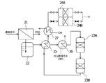
- FIG. 2 conceptually shows a second embodiment of the source gas purification apparatus according to the present invention.
- the second embodiment shows the first embodiment at a more specific level.
- the manner of illustration of the second embodiment in FIG. 2 is apparently different in comparison with the first embodiment, and is described as the second embodiment in order to facilitate the description.
- the CO 2 separation device 21 is the CO 2 separation device 1
- the chemical absorption device 22 is the chemical absorption device 2
- the COS conversion catalyst device 23 A is the COS conversion catalyst device 3 A.
- the conversion catalyst device 23B corresponds to the RSH conversion catalyst device 3B, and the adsorption / desorption devices 24A and 24B correspond to the adsorption / desorption device 4, and the contents described for the first embodiment of these constituent devices are the same as those of this embodiment. It is incorporated into the form. In FIG. 2, the H 2 S combustion device, the NGL recovery device, and the limestone gypsum desulfurization device are not shown.
- the source gas is introduced into the CO 2 separation device 21.
- the CO 2 separation device 21 separates and removes CO 2 contained in the source gas from other gas components by a separation membrane. If the present invention is to feed gas membrane separation as a target for CO 2 ratio in the feed gas, the gas on the primary side outlet proportion of CO 2 is reduced in film, the secondary side CO 2 A gas with an increased proportion of is obtained. If the ratio of CO 2 in the primary side outlet gas of the membrane does not reach the target, it is combined with the absorption method. That is, the chemical absorption device 22 plays this role.
- heat can be recovered by burning the off-gas on the secondary side (OFG in FIG. 2) and using it as a heat source.
- the off gas may be pressurized again, recycled to the primary side, and recovered as a product.
- heat recovery is performed by burning off gas (OFG in FIG. 2) on the secondary side.
- the raw material gas from which CO 2 has been removed is introduced into the chemical absorption device 22.
- the chemical absorption device 22 removes H 2 S by chemical absorption. Furthermore, in addition to the removal of H 2 S, the chemical absorption device 22 can also remove remaining CO 2 that has not been completely removed by the CO 2 separation device 1. In addition, a part of COS is also absorbed and removed.
- the chemical absorption device 22 dissipates H 2 S, COS, and CO 2 by heating the amine absorption liquid. H 2 S, COS, and CO 2 are fed into the H 2 S combustor. Further, if the CO 2 concentration in the feed gas is low, the separated and removed to CO 2, using only a chemical absorber 2, it may be omitted CO 2 separator 1.
- the raw material gas from which CO 2 and H 2 S have been removed is heated by the heat exchanger 25 with the gas from the RSH conversion catalyst device 23 B, and further, the heat exchanger 26 burns the H 2 S combustion gas and the off gas. It is heated by the resulting combustion gas, preferably to a temperature above 300.degree.
- the raw material gas from which CO 2 and H 2 S have been removed is sent to the COS conversion catalyst device 23A and then to the RSH conversion catalyst device 23B.
- Material gas has a temperature exceeding 300 ° C.
- COS conversion catalyst device 23A of the pre-swirl COS is converted to H 2 S, at RSH conversion catalyst device 23B on the downstream, RSH is converted to H 2 S Be done.
- the COS conversion catalyst device 23A and the RSH conversion catalyst device 23B are preferably arranged in tandem so that the smaller one of COS and RSH is to be treated first.
- generation system becomes large abundance of H 2 S, because the reaction in the direction that produces a chemical equilibrium on H 2 S becomes difficult to proceed.
- a gas containing hydrocarbon, H 2 S, and H 2 O obtained after converting COS and RSH into H 2 S is introduced into the adsorption / desorption devices 24 A, 24 B via the cooler 27.
- the cooling water cools the gas.
- the adsorption and desorption devices 24A and 24B adsorb and remove H 2 S and H 2 O contained in the gas.
- the gas from which H 2 S and H 2 O have been removed is a hydrocarbon of high purity, and is sent to an NGL recovery device (not shown).
- the adsorption / desorption devices 24A, 24B are regenerated by desorbing H 2 S and H 2 O by heating or depressurization.
- the desorbed H 2 S and H 2 O are carried by C 1 hydrocarbon (methane) supplied from the NGL recovery device, join with the raw material gas from the CO 2 separation device 21, and are introduced into the chemical absorption device 22 .
- adsorption-desorption apparatus 24B are closed, H 2 S, and H 2 O is adsorbed by the adsorption and desorption apparatus 24A.
- H 2 S and H 2 O can be desorbed by opening a valve (not shown) and heating / depressurizing the adsorption / desorption device 24B.
- the adsorption and desorption devices 24A and 24B alternately repeat adsorption and desorption to enable continuous operation of the entire device.
- the second embodiment describes the first embodiment at a more specific level. Therefore, the second embodiment has the same effect as the first embodiment. It is understood that, in addition to such basic effects, in the second embodiment, the combustion of the off gas has the effect of improving the thermal efficiency of the system. Further, in the second embodiment, it is also understood that by alternately repeating adsorption / desorption for the two adsorption towers constituting the adsorption / desorption device, there is an effect that continuous operation of the entire device is enabled. Ru.
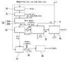
- FIG. 3 conceptually shows a third embodiment of the source gas purification apparatus according to the present invention.
- This third embodiment as the first H 2 S removal device employs a H 2 S separation device 31, the sulfur compounds other than H 2 S as a conversion device of the sulfur compounds is converted to H 2 S is The same sulfur compound conversion catalyst device 32 as that of the first embodiment is adopted, and a chemical absorption device 33 similar to that of the first embodiment is adopted as a second H 2 S removal device.
- the CO 2 separation device 34, the adsorption and desorption device 35, the NGL recovery device 36, the H 2 S combustion device 37, and the limestone gypsum desulfurization device 38 have the same basic configuration as the first embodiment.
- the contents described for the first embodiment for constituent devices with the same name other than the H 2 S separation device 31 are basically incorporated in the present embodiment.
- the H 2 S separation device 31 uses an H 2 S separation membrane to contain sulfur compounds other than CO 2 , H 2 S, H 2 S (mainly COS or RSH), H 2 O, in addition to hydrocarbons such as methane. It is an apparatus for selectively removing H 2 S from natural gas contained as an impurity.
- the H 2 S separation membrane it is possible to use a material having the property of being easy to permeate H 2 S and carbon dioxide gas as described in JP-A-7-155787, etc. and to hardly permeate methane and the like.
- an H 2 S separation membrane one composed of silicon, polyimide, and cellulose acetate can be exemplified.
- adsorption of H 2 S by molecular sieve or zinc oxide may be performed.
- the present embodiment will be described by describing the action mechanism of the constituent devices.
- the third embodiment of the method for purifying a source gas according to the present invention will be described with an explanation of such an action mechanism.
- the source gas is introduced into the CO 2 separation device 34.
- the CO 2 separation device 34 separates and removes CO 2 contained in the source gas from other gas components by a separation membrane.
- the raw material gas from which CO 2 has been removed is introduced into the H 2 S separation device 31.
- H 2 S is removed by an H 2 S separation membrane or an adsorbent.
- the removed H 2 S is burned by the H 2 S combustor 37.
- the remaining CO 2 not completely removed by the CO 2 separation device 34 can be removed.
- the raw material gas from which CO 2 and H 2 S have been removed is sent to the sulfur compound conversion catalyst device 32.
- the source gas from which CO 2 and H 2 S have been removed contains, in addition to hydrocarbons such as methane, sulfur compounds other than H 2 S (denoted as COS and RSH in FIG. 3), H 2 O It is done.
- steam at a temperature exceeding 300 ° C. is introduced into each of the COS conversion catalyst device 32A and the RSH conversion catalyst device 32B that constitute the sulfur compound conversion catalyst device 32, and COS is introduced by the COS conversion catalyst device 32A of the front stream. Convert to H 2 S and turn RSH to H 2 S in the downstream RSH conversion catalyst unit 32 B.
- Gas containing hydrocarbon, H 2 S, CO 2 (by-product), and H 2 O which is obtained after converting COS and RSH to H 2 S by the sulfur compound conversion catalyst device 32, is supplied to the chemical absorption device 33. Introduce.
- the chemical absorption device 33 adsorbs and removes H 2 S and CO 2 contained in the gas.
- the gas from which H 2 S and CO 2 have been removed contains hydrocarbons and H 2 O, and is sent to the adsorption / desorption device 35 via the cooler 39.
- H 2 O is adsorbed and removed.
- the adsorption and desorption device 35 is regenerated by desorbing H 2 O by heating and depressurization.
- the desorbed H 2 O is transported by the C1 hydrocarbon (methane) supplied from the NGL recovery device 5 and joins the C1 hydrocarbon discharge line (at * in the figure).
- the gas sent to the NGL recovery unit 36 is separated into C1 hydrocarbon (methane), C2-4 hydrocarbon (hydrocarbon having 2 to 4 carbon atoms), and C5 + hydrocarbon (hydrocarbon having 5 or more carbon atoms). Ru.
- C1 hydrocarbons are partially sent to the adsorption / desorption device 35 as described above, and the other portion is sent to the H 2 S combustion device 37.
- C2-4 hydrocarbons, and C5 + hydrocarbons are recovered as products.
- the chemical absorption device 33 dissipates H 2 S and CO 2 by heating the amine absorption liquid.
- the H 2 S and CO 2 are fed to the H 2 S combustion device 37.
- the C 1 hydrocarbon from the NGL recovery unit 36 is also fed to the H 2 S combustion unit 37 as described above.
- the C 1 hydrocarbon and H 2 S are burned by the H 2 S combustion device 37.
- the exhaust gas obtained after burning the C1 hydrocarbon and H 2 S is sent to the limestone gypsum desulfurization device 38 via the heat exchanger 40.
- the heat obtained by the heat exchanger 40 can be used to generate steam at a temperature exceeding 300 ° C. supplied to the sulfur compound conversion catalyst device 32.
- the limestone type desulfurization apparatus 38 recovers SO 2 (sulfurous acid gas) obtained by burning H 2 S and COS as gypsum (CaSO 4 ⁇ 2H 2 O).
- SO 2 sulfurous acid gas
- gypsum limestone
- limestone (CaCO 3 ) is suspended in water to make a limestone slurry, this slurry is brought into contact with the exhaust gas in an absorption tower, and SO 2 in the exhaust gas is absorbed and removed, Oxygen and oxygen in the air introduced into the absorber make gypsum.
- the chemical absorption device 33 may not be provided.
- all gases containing hydrocarbons, H 2 S and H 2 O are sent from the sulfur compound conversion catalyst device 32 to the adsorption and desorption device 35 to adsorb H 2 S and H 2 O.
- high purity hydrocarbons are obtained and sent to the NGL recovery unit 36.
- H 2 S and H 2 O are desorbed from the adsorption / desorption device 35 by the C 1 hydrocarbon from the NGL recovery device 36, and are sent to the H 2 S separation device 31.
- the other processing can be the same as that of the third embodiment.
- FIG. 4 conceptually shows a fourth embodiment of the source gas purification apparatus according to the present invention.
- the sulfur compound conversion catalyst device 3 is provided with the mercury removing device 10 immediately before.
- hydrocarbons such as methane, natural gas containing sulfur compounds other than CO 2 , H 2 S, H 2 S (mainly COS and RSH), H 2 O, Hg as impurities, It is used as the source gas to be processed.
- components given the same reference numerals as in FIG. 1 have substantially the same configuration as FIG. 1 and perform substantially the same function.
- the operation mechanism of the present embodiment that is, one embodiment of the method of purifying the source gas according to the present invention is substantially the same as that described with reference to FIG. However, it is different in that the process of the mercury removal which makes the mercury removal apparatus 10 act is added.
- the mercury removal apparatus 10 is installed for the purpose of removing mercury (Hg alone or organic mercury) which is a trace component.
- mercury removal apparatus 10 which can be employ
- adopted what makes activated carbon a physical adsorption agent can also be used as a molecular sieve. However, such a physical adsorption method tends to increase the capacity of the device. Therefore, as a guard reactor for the sulfur compound conversion catalyst device 3, one incorporating a mercury adsorbent (chemical adsorbent) is preferable.
- a mercury adsorption agent incorporated As a mercury adsorption agent incorporated, a sulfide (CuS, and / or MoS 3 or the like) is suitable.
- a mercury adsorbent With such a form of employing a mercury adsorbent, it is possible to realize a large amount of adsorption and save space because of chemical adsorption. In addition, since mercury is fixedly adsorbed as sulfide, immobilization is possible regardless of mercury species.
- the heating temperature of the mercury adsorbent is around 100 to 300 ° C., and a heat source similar to that for heating the sulfur compound conversion catalyst device 3 can be employed.
- the fourth embodiment in addition to the effects of the first embodiment, it is also possible to expect an effect that mercury contained in the source gas can be effectively removed. In addition, an effect of preventing the poisoning of the conversion catalyst used for the sulfur compound conversion catalyst device 3 present in the rear stream can also be expected.
Landscapes
- Chemical & Material Sciences (AREA)
- Engineering & Computer Science (AREA)
- Oil, Petroleum & Natural Gas (AREA)
- General Chemical & Material Sciences (AREA)
- Chemical Kinetics & Catalysis (AREA)
- Analytical Chemistry (AREA)
- Combustion & Propulsion (AREA)
- Organic Chemistry (AREA)
- Environmental & Geological Engineering (AREA)
- Biomedical Technology (AREA)
- Health & Medical Sciences (AREA)
- Treating Waste Gases (AREA)
- Gas Separation By Absorption (AREA)
- Separation Using Semi-Permeable Membranes (AREA)
- Separation Of Gases By Adsorption (AREA)
Abstract
La présente invention concerne un appareil de purification de gaz source comprenant : un premier dispositif d'élimination de H2S 2 qui élimine H2S d'un gaz source qui comprend au moins un hydrocarbure, H2S et un composé de soufre autre que H2S ; un dispositif de conversion de composé de soufre 3 qui convertit le composé de soufre autre que H2S en H2S ; et un second dispositif d'élimination de H2S 4 qui permet d'éliminer le H2S converti.
Priority Applications (1)
| Application Number | Priority Date | Filing Date | Title |
|---|---|---|---|
| US15/571,317 US20180119039A1 (en) | 2015-07-03 | 2016-06-15 | Source gas purification apparatus and purification method |
Applications Claiming Priority (2)
| Application Number | Priority Date | Filing Date | Title |
|---|---|---|---|
| JP2015134624A JP2017014437A (ja) | 2015-07-03 | 2015-07-03 | 原料ガスの精製装置、及び精製方法 |
| JP2015-134624 | 2015-07-03 |
Publications (1)
| Publication Number | Publication Date |
|---|---|
| WO2017006724A1 true WO2017006724A1 (fr) | 2017-01-12 |
Family
ID=57685021
Family Applications (1)
| Application Number | Title | Priority Date | Filing Date |
|---|---|---|---|
| PCT/JP2016/067790 Ceased WO2017006724A1 (fr) | 2015-07-03 | 2016-06-15 | Appareil de purification de gaz source et procédé de purification |
Country Status (3)
| Country | Link |
|---|---|
| US (1) | US20180119039A1 (fr) |
| JP (1) | JP2017014437A (fr) |
| WO (1) | WO2017006724A1 (fr) |
Families Citing this family (26)
| Publication number | Priority date | Publication date | Assignee | Title |
|---|---|---|---|---|
| DE102014118345A1 (de) * | 2014-12-10 | 2016-06-16 | L'Air Liquide, Société Anonyme pour l'Etude et l'Exploitation des Procédés Georges Claude | Verfahren und Anlage zur Reinigung von Rohsynthesegas |
| JP2020062571A (ja) * | 2017-02-09 | 2020-04-23 | 独立行政法人石油天然ガス・金属鉱物資源機構 | 硫化水素除去システム及び硫化水素除去方法 |
| US10696906B2 (en) | 2017-09-29 | 2020-06-30 | Marathon Petroleum Company Lp | Tower bottoms coke catching device |
| US12000720B2 (en) | 2018-09-10 | 2024-06-04 | Marathon Petroleum Company Lp | Product inventory monitoring |
| US12031676B2 (en) | 2019-03-25 | 2024-07-09 | Marathon Petroleum Company Lp | Insulation securement system and associated methods |
| US11975316B2 (en) | 2019-05-09 | 2024-05-07 | Marathon Petroleum Company Lp | Methods and reforming systems for re-dispersing platinum on reforming catalyst |
| CN110052138A (zh) * | 2019-05-13 | 2019-07-26 | 江苏龙泰环保设备制造有限公司 | 一种硬质聚氨酯泡沫塑料生产废气净化处理系统 |
| CA3212048A1 (fr) | 2019-05-30 | 2020-11-30 | Marathon Petroleum Company Lp | Procedes et systemes pour minimiser les emissions de so2 et de co dans les rechauffeurs de tirage naturel |
| WO2021097363A1 (fr) * | 2019-11-15 | 2021-05-20 | Susteon Inc. | Production de carbure de silicium particulaire de grande pureté par pyrolyse d'hydrocarbures |
| CA3109606C (fr) | 2020-02-19 | 2022-12-06 | Marathon Petroleum Company Lp | Melanges de mazout a faible teneur en soufre pour la stabilite de l`huile residuaire paraffinique et methodes connexes |
| US11578278B2 (en) * | 2020-08-01 | 2023-02-14 | Honeywell International Inc. | Renewable transportation fuel process with thermal oxidation system |
| US11898109B2 (en) | 2021-02-25 | 2024-02-13 | Marathon Petroleum Company Lp | Assemblies and methods for enhancing control of hydrotreating and fluid catalytic cracking (FCC) processes using spectroscopic analyzers |
| US20250012744A1 (en) | 2021-02-25 | 2025-01-09 | Marathon Petroleum Company Lp | Methods and assemblies for enhancing control of refining processes using spectroscopic analyzers |
| US12461022B2 (en) | 2021-02-25 | 2025-11-04 | Marathon Petroleum Company Lp | Methods and assemblies for determining and using standardized spectral responses for calibration of spectroscopic analyzers |
| US12473500B2 (en) | 2021-02-25 | 2025-11-18 | Marathon Petroleum Company Lp | Assemblies and methods for enhancing control of fluid catalytic cracking (FCC) processes using spectroscopic analyzers |
| US11702600B2 (en) | 2021-02-25 | 2023-07-18 | Marathon Petroleum Company Lp | Assemblies and methods for enhancing fluid catalytic cracking (FCC) processes during the FCC process using spectroscopic analyzers |
| US11905468B2 (en) | 2021-02-25 | 2024-02-20 | Marathon Petroleum Company Lp | Assemblies and methods for enhancing control of fluid catalytic cracking (FCC) processes using spectroscopic analyzers |
| US11692141B2 (en) | 2021-10-10 | 2023-07-04 | Marathon Petroleum Company Lp | Methods and systems for enhancing processing of hydrocarbons in a fluid catalytic cracking unit using a renewable additive |
| CN114191929B (zh) * | 2021-12-24 | 2022-12-06 | 常州化工设计院有限公司 | 一种化工尾气处理工艺 |
| US11802257B2 (en) | 2022-01-31 | 2023-10-31 | Marathon Petroleum Company Lp | Systems and methods for reducing rendered fats pour point |
| US12311305B2 (en) | 2022-12-08 | 2025-05-27 | Marathon Petroleum Company Lp | Removable flue gas strainer and associated methods |
| CN116477580B (zh) * | 2023-04-26 | 2025-01-03 | 福州大学 | 一种可循环使用的硫化氢吸附剂解析气制硫磺的工艺及系统 |
| CA3238046A1 (en) | 2023-05-12 | 2025-07-07 | Marathon Petroleum Company Lp | Systems, apparatuses, and methods for sample cylinder inspection, pressurization, and sample disposal |
| US12533615B2 (en) | 2023-06-02 | 2026-01-27 | Marathon Petroleum Company Lp | Methods and systems for reducing contaminants in a feed stream |
| US12415962B2 (en) | 2023-11-10 | 2025-09-16 | Marathon Petroleum Company Lp | Systems and methods for producing aviation fuel |
| US12599848B2 (en) | 2024-06-03 | 2026-04-14 | Marathon Petroleum Company Lp | Systems, analyzers, controllers, and associated methods to enhance fluid separation for distillation operations |
Citations (8)
| Publication number | Priority date | Publication date | Assignee | Title |
|---|---|---|---|---|
| JPH0230290B2 (fr) * | 1981-05-26 | 1990-07-05 | Sheru Intern Risaachi Maachatsupii Bv | |
| JPH0345118B2 (fr) * | 1981-08-24 | 1991-07-10 | Sheru Intern Risaachi Maachatsupii Bv | |
| JPH11104451A (ja) * | 1997-10-03 | 1999-04-20 | Mitsubishi Heavy Ind Ltd | ガス精製方法及びガス精製装置 |
| JPH11221431A (ja) * | 1998-02-04 | 1999-08-17 | Babcock Hitachi Kk | 硫黄分回収方法 |
| JPH11241076A (ja) * | 1998-02-26 | 1999-09-07 | Hitachi Ltd | ガス精製方法 |
| JP2005068337A (ja) * | 2003-08-26 | 2005-03-17 | Matsushita Electric Works Ltd | 液化石油ガスの脱硫装置及び硫化カルボニル分解触媒 |
| JP2007016149A (ja) * | 2005-07-08 | 2007-01-25 | Chiyoda Corp | 天然ガスからの硫黄化合物の除去方法 |
| US20140357926A1 (en) * | 2013-05-31 | 2014-12-04 | Uop Llc | Removal of sulfur compounds from natural gas streams |
Family Cites Families (2)
| Publication number | Priority date | Publication date | Assignee | Title |
|---|---|---|---|---|
| CA2637395C (fr) * | 2006-02-01 | 2011-11-22 | Fluor Technologies Corporation | Configurations et procedes d'elimination de mercaptans de gaz d'alimentation |
| WO2008020994A1 (fr) * | 2006-08-09 | 2008-02-21 | Fluor Technologies Corporation | Dispositifs et procédés de suppression de mercaptans des gaz d'alimentation |
-
2015
- 2015-07-03 JP JP2015134624A patent/JP2017014437A/ja active Pending
-
2016
- 2016-06-15 WO PCT/JP2016/067790 patent/WO2017006724A1/fr not_active Ceased
- 2016-06-15 US US15/571,317 patent/US20180119039A1/en not_active Abandoned
Patent Citations (8)
| Publication number | Priority date | Publication date | Assignee | Title |
|---|---|---|---|---|
| JPH0230290B2 (fr) * | 1981-05-26 | 1990-07-05 | Sheru Intern Risaachi Maachatsupii Bv | |
| JPH0345118B2 (fr) * | 1981-08-24 | 1991-07-10 | Sheru Intern Risaachi Maachatsupii Bv | |
| JPH11104451A (ja) * | 1997-10-03 | 1999-04-20 | Mitsubishi Heavy Ind Ltd | ガス精製方法及びガス精製装置 |
| JPH11221431A (ja) * | 1998-02-04 | 1999-08-17 | Babcock Hitachi Kk | 硫黄分回収方法 |
| JPH11241076A (ja) * | 1998-02-26 | 1999-09-07 | Hitachi Ltd | ガス精製方法 |
| JP2005068337A (ja) * | 2003-08-26 | 2005-03-17 | Matsushita Electric Works Ltd | 液化石油ガスの脱硫装置及び硫化カルボニル分解触媒 |
| JP2007016149A (ja) * | 2005-07-08 | 2007-01-25 | Chiyoda Corp | 天然ガスからの硫黄化合物の除去方法 |
| US20140357926A1 (en) * | 2013-05-31 | 2014-12-04 | Uop Llc | Removal of sulfur compounds from natural gas streams |
Also Published As
| Publication number | Publication date |
|---|---|
| JP2017014437A (ja) | 2017-01-19 |
| US20180119039A1 (en) | 2018-05-03 |
Similar Documents
| Publication | Publication Date | Title |
|---|---|---|
| JP2017014437A (ja) | 原料ガスの精製装置、及び精製方法 | |
| CA2745351C (fr) | Separation d'un circuit de gaz synthetique acide | |
| CN103596663B (zh) | 二氧化碳分离系统 | |
| RU2417825C2 (ru) | Способ очистки газов, полученных из установки газификации | |
| Ebner et al. | State-of-the-art adsorption and membrane separation processes for carbon dioxide production from carbon dioxide emitting industries | |
| US10005666B2 (en) | Claus process for sulfur recovery with intermediate water vapor removal by adsorption | |
| RU2349371C2 (ru) | Способ разделения отходящего газа или дыма, образующегося при окислении топлива, и выделения из него диоксида углерода | |
| CN103561844B (zh) | 用于从生物气中分离和纯化甲烷的方法和系统 | |
| AU2012347153B2 (en) | Method and device for separating hydrogen sulfide and hydrogen production system using the same | |
| JPH04227017A (ja) | 燃焼排ガスからの窒素及びアルゴン副製品回収を伴なう二酸化炭素の製造 | |
| US10239756B1 (en) | Process for sulfur recovery from acid gas stream without catalytic Claus reactors | |
| CN107567350B (zh) | 用于从气体物流中除去和回收h2s的改进方法 | |
| US20190314759A1 (en) | Process for the removal of hydrogen chloride and sulfur oxides from a gas stream by absorption | |
| CN1208360A (zh) | 从气体中除去含硫的污染物、芳族化合物和烃的方法 | |
| JP6055920B2 (ja) | 水素回収方法 | |
| RU2551510C2 (ru) | Способ удаления вредных веществ из диоксида углерода и устройство для его осуществления | |
| RU2846416C1 (ru) | Способ переработки углеводородного газа, содержащего меркаптаны | |
| Castro González | Selection of adsorbents for CO2 recovery from process gas streams using pressure swing adsorption processes | |
| JPS61207494A (ja) | H↓2s及びco↓2が共存するガスの脱硫法 |
Legal Events
| Date | Code | Title | Description |
|---|---|---|---|
| 121 | Ep: the epo has been informed by wipo that ep was designated in this application |
Ref document number: 16821194 Country of ref document: EP Kind code of ref document: A1 |
|
| WWE | Wipo information: entry into national phase |
Ref document number: 15571317 Country of ref document: US |
|
| NENP | Non-entry into the national phase |
Ref country code: DE |
|
| 122 | Ep: pct application non-entry in european phase |
Ref document number: 16821194 Country of ref document: EP Kind code of ref document: A1 |