WO2017006830A1 - Dispositif de moulage de saillie, procédé de moulage de saillie et article moulé - Google Patents
Dispositif de moulage de saillie, procédé de moulage de saillie et article moulé Download PDFInfo
- Publication number
- WO2017006830A1 WO2017006830A1 PCT/JP2016/069332 JP2016069332W WO2017006830A1 WO 2017006830 A1 WO2017006830 A1 WO 2017006830A1 JP 2016069332 W JP2016069332 W JP 2016069332W WO 2017006830 A1 WO2017006830 A1 WO 2017006830A1
- Authority
- WO
- WIPO (PCT)
- Prior art keywords
- punch
- die
- workpiece
- protrusion
- punch portion
- Prior art date
- Legal status (The legal status is an assumption and is not a legal conclusion. Google has not performed a legal analysis and makes no representation as to the accuracy of the status listed.)
- Ceased
Links
Images


Classifications
-
- B—PERFORMING OPERATIONS; TRANSPORTING
- B21—MECHANICAL METAL-WORKING WITHOUT ESSENTIALLY REMOVING MATERIAL; PUNCHING METAL
- B21D—WORKING OR PROCESSING OF SHEET METAL OR METAL TUBES, RODS OR PROFILES WITHOUT ESSENTIALLY REMOVING MATERIAL; PUNCHING METAL
- B21D28/00—Shaping by press-cutting; Perforating
- B21D28/24—Perforating, i.e. punching holes
- B21D28/34—Perforating tools; Die holders
- B21D28/343—Draw punches
-
- B—PERFORMING OPERATIONS; TRANSPORTING
- B21—MECHANICAL METAL-WORKING WITHOUT ESSENTIALLY REMOVING MATERIAL; PUNCHING METAL
- B21D—WORKING OR PROCESSING OF SHEET METAL OR METAL TUBES, RODS OR PROFILES WITHOUT ESSENTIALLY REMOVING MATERIAL; PUNCHING METAL
- B21D22/00—Shaping without cutting, by stamping, spinning, or deep-drawing
- B21D22/02—Stamping using rigid devices or tools
-
- B—PERFORMING OPERATIONS; TRANSPORTING
- B21—MECHANICAL METAL-WORKING WITHOUT ESSENTIALLY REMOVING MATERIAL; PUNCHING METAL
- B21D—WORKING OR PROCESSING OF SHEET METAL OR METAL TUBES, RODS OR PROFILES WITHOUT ESSENTIALLY REMOVING MATERIAL; PUNCHING METAL
- B21D28/00—Shaping by press-cutting; Perforating
- B21D28/02—Punching blanks or articles with or without obtaining scrap; Notching
- B21D28/16—Shoulder or burr prevention, e.g. fine-blanking
-
- B—PERFORMING OPERATIONS; TRANSPORTING
- B21—MECHANICAL METAL-WORKING WITHOUT ESSENTIALLY REMOVING MATERIAL; PUNCHING METAL
- B21D—WORKING OR PROCESSING OF SHEET METAL OR METAL TUBES, RODS OR PROFILES WITHOUT ESSENTIALLY REMOVING MATERIAL; PUNCHING METAL
- B21D28/00—Shaping by press-cutting; Perforating
- B21D28/24—Perforating, i.e. punching holes
- B21D28/26—Perforating, i.e. punching holes in sheets or flat parts
-
- B—PERFORMING OPERATIONS; TRANSPORTING
- B21—MECHANICAL METAL-WORKING WITHOUT ESSENTIALLY REMOVING MATERIAL; PUNCHING METAL
- B21D—WORKING OR PROCESSING OF SHEET METAL OR METAL TUBES, RODS OR PROFILES WITHOUT ESSENTIALLY REMOVING MATERIAL; PUNCHING METAL
- B21D37/00—Tools as parts of machines covered by this subclass
- B21D37/10—Die sets; Pillar guides
- B21D37/12—Particular guiding equipment, e.g. pliers; Special arrangements for interconnection or cooperation of dies
-
- B—PERFORMING OPERATIONS; TRANSPORTING
- B21—MECHANICAL METAL-WORKING WITHOUT ESSENTIALLY REMOVING MATERIAL; PUNCHING METAL
- B21D—WORKING OR PROCESSING OF SHEET METAL OR METAL TUBES, RODS OR PROFILES WITHOUT ESSENTIALLY REMOVING MATERIAL; PUNCHING METAL
- B21D53/00—Making other particular articles
- B21D53/26—Making other particular articles wheels or the like
- B21D53/28—Making other particular articles wheels or the like gear wheels
-
- B—PERFORMING OPERATIONS; TRANSPORTING
- B21—MECHANICAL METAL-WORKING WITHOUT ESSENTIALLY REMOVING MATERIAL; PUNCHING METAL
- B21J—FORGING; HAMMERING; PRESSING METAL; RIVETING; FORGE FURNACES
- B21J5/00—Methods for forging, hammering, or pressing; Special equipment or accessories therefor
- B21J5/02—Die forging; Trimming by making use of special dies ; Punching during forging
-
- B—PERFORMING OPERATIONS; TRANSPORTING
- B21—MECHANICAL METAL-WORKING WITHOUT ESSENTIALLY REMOVING MATERIAL; PUNCHING METAL
- B21K—MAKING FORGED OR PRESSED METAL PRODUCTS, e.g. HORSE-SHOES, RIVETS, BOLTS OR WHEELS
- B21K1/00—Making machine elements
- B21K1/28—Making machine elements wheels; discs
- B21K1/30—Making machine elements wheels; discs with gear-teeth
-
- B—PERFORMING OPERATIONS; TRANSPORTING
- B21—MECHANICAL METAL-WORKING WITHOUT ESSENTIALLY REMOVING MATERIAL; PUNCHING METAL
- B21K—MAKING FORGED OR PRESSED METAL PRODUCTS, e.g. HORSE-SHOES, RIVETS, BOLTS OR WHEELS
- B21K23/00—Making other articles
Definitions
- the present invention relates to a projection forming apparatus, a projection forming method, and a molded product.
- the fine blanking method is a method of performing high-precision shearing by plastically deforming a workpiece by applying a compressive force.
- the fine blanking method is difficult to form when the height of the protrusion is equal to or greater than the plate thickness. This is because the punch diameter and the die hole diameter are generally the same, and therefore, if the height of the protrusion is greater than or equal to the plate thickness, the workpiece is cut by shearing force and cannot be processed.
- An object of the present invention is to provide a protruding portion forming apparatus, a protruding portion forming method, and a molded product that can be formed with a height equal to or greater than the plate thickness, have sharp edges, and prevent the occurrence of cracks.
- the present invention relates to a die portion provided with a die hole, a large punch portion that can advance and retreat in a first direction toward the die portion side, and cannot be inserted into the die hole, and the large punch portion.
- a projection forming apparatus that deforms the workpiece to form a projection by pressing the punch toward the die by the punch.
- the distance d1 between the side surface of the small punch portion and the side surface of the large punch portion and the distance d2 between the side surface of the small punch portion and the inner surface of the die hole satisfy the relationship d2 ⁇ d1. It is preferable that it exists in.
- the distance d2 between the side surface of the small punch portion and the inner surface of the die hole and the plate thickness T of the workpiece have a relationship of d2 ⁇ T.
- the lower surface of the small punch portion is provided with a slope inclined in a direction in which the thickness of the small punch portion becomes thinner toward the edge of the small punch portion.
- the present invention provides a placing step of placing a workpiece on a die portion provided with a die hole, a large punch portion that cannot be inserted into the die hole, and the die portion side from the large punch portion.
- the punch part having a small punch part of a size that can be inserted into the die hole is moved in the first direction toward the die part side, and is disposed between the die part and the punch part.
- the distance d1 between the side surface of the small punch portion and the side surface of the large punch portion and the distance d2 between the side surface of the small punch portion and the inner surface of the die hole satisfy the relationship of d2 ⁇ d1. It is preferable that it exists in.
- the distance d2 between the side surface of the small punch portion and the inner surface of the die hole and the plate thickness T of the workpiece have a relationship of d2 ⁇ T.
- the method in the punching step, a slope inclined in a direction in which the thickness of the small punch portion becomes thinner toward the edge of the small punch portion is provided on the lower surface of the small punch portion. It is preferable that the method includes a first step of forming a protruding portion by the punched portion and a second step of forming the protruding portion by a punched portion having a flat bottom surface of the small punch portion.
- the present invention is also a molded product including a flat portion having a thickness T and a protrusion protruding from one surface side of the flat portion, and the other surface side of the protrusion in the molded product includes a first portion.
- the thickness T of the flat portion is a molded product that satisfies the relationship d2 ⁇ T.
- the molded product can be molded such that H ⁇ T when the height H is from the one surface of the flat portion to the upper surface on the one surface side of the protrusion.
- the width S1 of the first recess, the width S2 of the second recess, and the width S3 of the protrusion on the one surface side satisfy a relationship of S2 ⁇ S3 ⁇ S1.
- FIG. 1A and 1B are schematic views of a projection forming apparatus, where FIG. 1A shows a state before processing the workpiece, and FIG. 1B shows a state after processing the workpiece.
- (A) is a photograph of the seat gear provided with the downward projection W1 as seen from below
- (b) is a photograph of the seat gear provided with the downward projection W1 as seen from above. It is the A section enlarged view of FIG.1 (b). It is a partial cross-sectional view of the molded product W01 after processing.
- FIG. 4 is a graph showing the results of measuring the hardness of portions P1 to P4 in FIG. 3 of the protrusions formed in the present embodiment. It is the figure which showed 2nd Embodiment of this invention, and respond
- the projection forming apparatus 1 is an apparatus for forming a projection on a plate-like workpiece W such as a steel plate.
- FIG. 1A shows a projection W1 molding in which the workpiece W is arranged on the projection forming apparatus 1.
- FIG. 1B is a schematic view showing a state in which the protrusion W1 is formed on the workpiece W arranged in the protrusion forming apparatus 1 in the previous state.
- the projection forming apparatus 1 of the present embodiment is used when the projection W1 is formed on a sheet gear as shown in FIG. 2, for example.
- FIG. 2A is a photograph of the seat gear provided with the downward projection W1, as viewed from below
- FIG. 2B is a photograph of the seat gear provided with the downward projection W1, as viewed from above.
- the surface area of the protrusion W1 on the side in contact with the die hole 12a is large.
- molds in the state which the protrusion part W1 protruded below as shown in FIG.2 (b) is demonstrated.
- the projection forming apparatus 1 includes a fixed unit 10, a moving unit 30 that moves up and down with respect to the fixed unit 10, and a pressing unit 50 that is held by the moving unit 30 and moves further with respect to the moving unit 30.
- “upper and lower” is the direction of the arrow shown in FIG. 1, and hereinafter, in this specification, the direction in which the moving unit 30 approaches the fixed unit 10 is downward (first direction), and the moving unit 30 is separated from the fixed unit 10. The direction is called upward.
- the fixing part 10 includes a die holder 11, a die part 12, and a guide post 13.
- the die holder 11 is manufactured by a substantially rectangular thick plate member.
- the shape of the die holder 11 is not limited to a rectangle.
- a through hole 11 a is provided at the center of the die holder 11.
- the guide post 13 extends upward from the outer periphery of the die holder 11 in the figure. In this embodiment, for example, four guide posts 13 (only two are shown in the figure) are provided.
- the die portion 12 is disposed on the inner side of the guide post 13 on the upper surface of the die holder 11 and is fixed to the die holder 11.
- the die part 12 is a metal member having a constant thickness, and a die hole 12a corresponding to the shape of the protrusion part W1 formed by the protrusion part forming apparatus 1 is provided in the center part.
- a plurality of guide holes 12b are provided outside the die hole 12a in the die portion 12.
- a lower mold part 20 that is substantially the same shape and the same size as the die hole 12a and determines the height of the protrusion W1 is disposed inside the die hole 12a.
- An upper end of a rod-shaped knockout member 21 for discharging the workpiece W is attached to the lower surface of the lower mold part 20.
- the lower end of the knockout member 21 extends downward from the above-described through hole 11a provided in the die holder 11, and is connected to a drive mechanism (not shown). The drive mechanism presses the lower mold part 20 upward via the knockout member 21.
- the moving unit 30 includes a punch holder 31, a backing plate 32, a guide pin 36, and a punch unit 40.
- the punch holder 31 is made of a thick plate member having substantially the same size as the die holder 11.
- a first through hole 31 a is provided on the outer periphery of the punch holder 31 at a position corresponding to the above-described guide post 13.
- a guide bush 31c is inserted and fixed in the first through hole 31a.
- the guide bush 31 c is a cylindrical material and extends below the punch holder 31.
- the guide post 13 is inserted into the guide bush 31c, and when the guide bush 31c moves along the outer periphery of the guide post 13, a stable vertical movement of the moving part 30 relative to the fixed part 10 is ensured.
- a plurality of second through holes 31b are provided on the inner side of the punch holder 31 with respect to the guide bush 31c.
- the backing plate 32 is attached to the inner side of the lower surface of the punch holder 31 from the position where the guide bush 31c is provided.
- a two-stage hole 33 continuing from the second through hole 31 b is provided at a position corresponding to the second through hole 31 b described above.
- the second step hole 33 has the same axis as the second through hole 31b, is continuous with the second through hole 31b, and has the same diameter as the second through hole 31b, and the same as the second through hole 31b.
- the second hole 33b has an axis, is provided below the first hole 33a, and has a smaller diameter than the first hole 33a.
- the guide pin 36 is attached to the lower surface on the outer peripheral side of the two-step hole 33 of the backing plate 32 and extends downward from the backing plate 32.
- the punch portion 40 is fixed to the lower surface of the central portion of the backing plate 32.
- the punch section 40 includes a large punch section 41 on the backing plate 32 side and a small punch section 42 on the workpiece W side.
- the holding part 50 includes a bolt member 34, a holding plate 37, and a coil spring 35.
- the bolt member 34 has a head portion 34a smaller than the diameter of the second through hole 31b and the first hole 33a and larger than the diameter of the second hole 33b, and an extension having a diameter smaller than the diameter of the second hole 33b. Part 34b.
- the bolt member 34 has the head portion 34 a facing upward, and the extending portion 34 b is inserted into the second through hole 31 b, the first hole 33 a, and the second hole 33 b and is screwed to the pressing plate 37.
- the coil spring 35 is disposed at a portion protruding from the backing plate 32 of the bolt member 34 (the bolt member 34 is inserted into the coil spring 35).
- the pressing plate 37 is disposed on the outer peripheral side of the punch portion 40.
- the holding plate 37 is a thick plate member, and a first opening 37a is formed at the center.
- the first opening 37a is substantially the same diameter as the large punch 41 of the punch 40, and the large punch 41 is the first. It can slide in the one opening 37a.
- a bottomed bolt fixing screw portion 37 b is provided on the outer peripheral side of the first opening 37 a on the upper surface of the pressing plate 37.
- the threaded portion 37b is provided at a position corresponding to the extending portion 34b of the bolt member 34 described above, and the distal end of the extending portion 34b is inserted and fixed to the threaded portion 37b.
- the coil spring 35 is disposed between the backing plate 32 and the pressing plate 37 on the outer periphery of the extending portion 34b.
- a second opening 37 c is provided at a position corresponding to the above-described guide pin 36 on the outer peripheral side of the first opening 37 a of the pressing plate 37.
- a guide pin 36 is inserted into the second opening 37c. The lower end of the guide pin 36 is further inserted into the guide hole 12b of the die part 12, and the guide pin 36 is guided straight by the guide hole 12b of the die part 12 and the second opening part 37c.
- the workpiece W is disposed on the die portion 12.
- the workpiece W is, for example, a hot rolled steel plate (SPFH590) for automobiles.
- the workpiece W When forming a protrusion on the workpiece W, the workpiece W is disposed on the die portion 12. At this time, it positions so that the projection part formation location in the to-be-processed body W may be located on the die hole 12a.
- the moving unit 30 of the projection forming apparatus 1 is positioned above the state of FIG. Next, the moving unit 30 is lowered by a driving mechanism (not shown), and the pressing plate 37 is brought into contact with the workpiece W. Then, the moving part 30 is lowered, and the lower surface of the small punch part 42 of the punch part 40 is brought into contact with the workpiece W as shown in FIG.
- the moving unit 30 is further pressed downward by the driving mechanism.
- the punch 40 is further lowered, and the small punch 42 and the large punch 41 press the workpiece W.
- the workpiece W undergoes plastic deformation to form a projection W1 having a desired shape.
- the moving part 30 is raised to separate the workpiece W from the small punch part 42 and the large punch part 41, and the lower mold part 20 is pushed up by the knockout member 21.
- the protrusion W1 of the workpiece W is pushed out from the die hole 12a, and the workpiece W can be taken out.
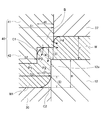
- FIG. 3 is an enlarged view of a portion A in FIG. 1B after the projection W1 is formed.
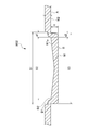
- FIG. 4 is a partial cross-sectional view of the molded product W01 after the projection W1 is molded.
- the distance between the side surface of the small punch portion 42 and the side surface of the large punch portion 41 is d1
- the distance between the side surface of the small punch portion 42 and the inner surface of the die hole 12a is d2.
- d2 ⁇ d1 (1) There is a relationship.
- the width S1 of the large punch portion 41, the width S2 of the small punch portion 42, and the width S3 of the die hole 12a in a predetermined cross section are: S2 ⁇ S3 ⁇ S1 (2)
- the distance d2 between the side surface of the small punch portion 42 and the inner surface of the die hole 12a when inserted into the die hole 12a is less than the plate thickness T of the workpiece W. T> d2 (3)
- the molded product W01 when viewed as a molded product W01, has a flat portion W2 having a thickness T and a thickness protruding downward from the one surface A side of the flat portion W2 in FIG. A projection portion W1 of T, and a rising portion P2 rising from the flat portion W2 to the projection portion W1.
- the distance d2 between the side surface of the small punch portion 42 and the inner surface of the die hole 12a when inserted into the die hole 12a is the thickness d2 of the rising portion P2 in the direction orthogonal to the thickness T direction of the flat portion W2.
- the height H from one surface A of the flat portion W2 to one surface B of the protrusion W1 is relative to the plate thickness T of the workpiece W.
- the portion on the opposite side to the one surface B of the protruding portion W1 is pressed by the punch portion 40, so that it is a concave portion.
- the recess is formed by further recessing the first recess D1 having the first width S1 that is approximately the same as the width S1 of the large punch portion 41, and a second recess that is approximately the same as the width S2 of the small punch portion 42.
- the width of the protrusion W1 on the one surface B side is equal to the width S3 of the die hole 12a, and as described above, S2 ⁇ S3 ⁇ S1 (2) Satisfy the relationship.
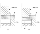
- FIG. 5A and 5B are views showing a comparative form, in which FIG. 5A shows a state in which the workpiece W is arranged on the die portion 12A of the comparative form, and FIG. W shows a state in which the protrusion W1 is formed.
- the punch part 40A of the comparative form does not have a large punch part as shown, but has only a small punch 42A.
- the distance d2 between the side surface of the small punch portion 42 and the inner surface of the die hole 12a is equal to or less than the plate thickness T of the workpiece W.
- the punch unit 40A when the punch unit 40A is lowered from the state of FIG. 5A, the punch unit 40A (small punch 42A) presses the workpiece W as shown in FIG. 5B.
- the indentation depth is increased, the workpiece W is plastically deformed.
- the edge of the protrusion becomes sharp.
- cracks are generated because tensile stress acts on the rising portion (P2 in the drawing) of the protrusion.
- the punch part 40 of this embodiment has a two-stage structure of a large punch part 41 and a small punch part 42 as shown in FIG.
- symbol B in FIG. 3 of the to-be-processed body W is pressed below by the large punch part 41, when shape
- the material of this B part flows to another part as shown by the arrow in FIG. That is, the material is pressed and flows, and the material is supplied to the portion where the tensile stress acts, so that the tensile stress is relaxed.
- the pressed portion 41 is forged and the hardness is increased.
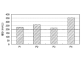
- FIG. 6 is a graph showing the results of measuring the hardness of the P1 to P4 portions in FIG. 3 of the workpiece W formed in the present embodiment.
- the position indicated by the dotted line is the hardness 197HV of the workpiece W itself. According to this embodiment, any part of P1 to P4 is hard, and the product strength can be improved.
- the protrusion W1 since the protrusion W1 also has a deformed form due to shearing, the corner portion R of the workpiece W after molding becomes sharp (angle drift hardly occurs). Therefore, fine irregularities can be formed. Further, the material that has flowed from the portion B not only increases the hardness, but also flows to other portions of the workpiece W. By this flow, a predetermined thickness can be secured at the portions P2 and P3 that are the rising portions of the protrusion W1. Further, the fluidized material is applied to the corner portion C1 between the large punch portion 41 and the small punch portion 42 in the workpiece W and the corner portion C2 between the lower mold portion 20 and the side surface of the die hole 12a. Since it is pushed in, the corner portion R of the workpiece W after molding becomes sharper (an angle drift is less likely to occur). Therefore, finer irregularities can be formed.
- the edge of the protrusion W1 becomes sharp in this way, the surface area of the portion in contact with the die hole 12a of the protrusion W1 increases. For this reason, when rotating the to-be-processed body W by making the projection part W1 contact other members, a big rotational torque can be taken out. Therefore, for example, it is suitable for manufacturing a projection such as a seat gear.
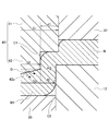
- FIG. 7 is a diagram showing a second embodiment of the present invention, and corresponds to FIG. 3 of the first embodiment.
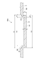
- FIG. 8 is a partial cross-sectional view of the molded product W02 after processing in the second embodiment.
- the difference between the present embodiment and the first embodiment is that the lower surface of the small punch portion 42 is provided with a slope 42a that is inclined in a direction in which the thickness of the small punch portion 42 decreases as it goes toward the edge of the small punch portion 42. This is the point.
- the molded product W02 of the second embodiment is different from the molded product W01 of the first embodiment in that a slope W1a is formed on the bottom surface of the second recess D2 by the slope 42a of the small punch portion 42. .
- the other parts are the same and will not be described.
- the punch portion 40 when the punch portion 40 is pressed against the surface of the workpiece W, since the inclined surface 42a is provided, the material present in the D portion of the workpiece W where the inclined surface 42a is located is shown in the drawing. It tends to flow in the direction indicated by the arrow. Therefore, the flow of the material to the portion P2 between the small punch portion 42 that is liable to crack and the inner surface of the die hole 12a is further promoted. Thereby, the protrusion part W1 which is hard to produce a crack (crack) still more than 1st Embodiment can be formed.
- the fluidized material flows to the other part of the workpiece W.
- This fluidized material is pushed into the corner C1 between the large punch 41 and the small punch 42 in the workpiece W and the corner C2 between the lower die 20 and the side surface of the die hole 12a.
- the corner portion R of the workpiece W (molded product W02) after molding becomes sharper. Therefore, finer irregularities can be formed.
- the protrusion forming apparatus 1 of the first embodiment shown in FIG. After forming the protrusion W1 on the workpiece W by the protrusion forming apparatus 1 of the second embodiment shown in FIG. 7, the protrusion forming apparatus 1 of the first embodiment shown in FIG. Thus, the workpiece W is further pressed to form the protrusion W1 more sharply.
- the punch portion 40 when the punch portion 40 is pressed against the surface of the workpiece W by the projection forming apparatus 1 shown in FIG. 7, the material of the surface of the workpiece W is transferred to the small punch portion 42 by the inclined surface 42 a. Flow outward.
- the edge portion can be made sharper by further flowing the material of the portion shown in FIG. 7 by the protruding portion forming apparatus 1 shown in FIG.
- FIG. 9 shows the fourth embodiment of the present invention and corresponds to FIG. 3 of the first embodiment.
- FIG. 10 is a partial cross-sectional view of a molded product W04 after processing in the fourth embodiment.
- the punch portion 40 of the projection forming apparatus 1 of the present embodiment is different from the first embodiment in that the projection 43 along the outer periphery of the small punch portion 42 is formed at the end of the surface of the small punch portion 42 on the workpiece W side. Is a point provided.
- the molded product W04 of the fourth embodiment is different from the molded product W01 of the first embodiment, as shown in FIG. 10, by the protrusion 43, a recess W1b is further formed at the corner of the bottom surface of the second recess D2. It is a point that has been.
- the other parts are the same and will not be described.
- the pressing load can be reduced as compared with the case where the entire lower surface of the punch portion 40 is pressed during molding.
- the protrusion 43 is provided when the punch portion 40 is pressed against the surface of the workpiece W, the material existing in the E portion of the workpiece W where the protrusion 43 is located is used. It tends to flow in the direction indicated by the arrow in the figure. Therefore, the flow of the material to the portion P2 between the small punch portion 42 that is liable to crack and the inner surface of the die hole 12a is further promoted. Thereby, the protrusion part W1 which is hard to produce a crack (crack) still more than 1st Embodiment can be formed. Moreover, the fluidized material not only increases the hardness but also flows to other parts of the workpiece W.
- This fluidized material is pushed into the corner C1 between the large punch 41 and the small punch 42 in the workpiece W and the corner C2 between the lower die 20 and the side surface of the die hole 12a.
- the corner portion R of the workpiece W after molding becomes sharper. Therefore, finer irregularities can be formed.
- the workpiece W is a hot rolled steel plate SPFH590.
- the mechanical properties are YS (yield stress) 522 MPa, TS (tensile strength) 604 MPa, EL (elongation) 26%, and the plate thickness is 2.9 mm. Two types of 5 mm were used. Table 1 shows measured values of the protrusion W1 of the workpiece W formed using the protrusion forming apparatus 1 of each embodiment.
- FIG. 3 shows which portion of each of the remaining direction thickness and (5) corner portion is.
- the height of the protruding portion is obtained when the thickness of the workpiece W is 2.9 mm or 2.5 mm.
- a protrusion W1 having a thickness H equal to or greater than the plate thickness T shown in Formula (4) (H ⁇ T) could be formed.
- the second embodiment, the third embodiment, and the fourth embodiment (2) remaining in the width direction when the thickness of the workpiece W is 2.9 mm or 2.5 mm.
- Plate thickness d2 (2) Plate thickness direction remaining plate thickness (4) 45 ° direction remaining plate thickness In a state where a predetermined thickness is secured within a range equal to or less than plate thickness T of workpiece W, protrusion W1 could be molded.
- the third embodiment in which the protrusion W1 is further formed based on the first embodiment has a smaller corner droop and a sharper protrusion.
- W1 could be molded.
- the corner droop is smaller than that in the first embodiment and the second embodiment, and sharp.
- a projection W1 could be formed.
Landscapes
- Engineering & Computer Science (AREA)
- Mechanical Engineering (AREA)
- Shaping Metal By Deep-Drawing, Or The Like (AREA)
Abstract
Priority Applications (4)
| Application Number | Priority Date | Filing Date | Title |
|---|---|---|---|
| US15/742,742 US11224909B2 (en) | 2015-07-07 | 2016-06-29 | Protrusion molding device, protrusion molding method, and molded article |
| AU2016291507A AU2016291507A1 (en) | 2015-07-07 | 2016-06-29 | Protrusion molding device, protrusion molding method, and molded article |
| EP16821299.1A EP3320997A4 (fr) | 2015-07-07 | 2016-06-29 | Dispositif de moulage de saillie, procédé de moulage de saillie et article moulé |
| CN201680051174.8A CN107921521A (zh) | 2015-07-07 | 2016-06-29 | 突起部成形装置、突起部成形方法以及成形品 |
Applications Claiming Priority (4)
| Application Number | Priority Date | Filing Date | Title |
|---|---|---|---|
| JP2015135834 | 2015-07-07 | ||
| JP2015-135834 | 2015-07-07 | ||
| JP2016124835A JP6673760B2 (ja) | 2015-07-07 | 2016-06-23 | 突起部成形装置、突起部成形方法 |
| JP2016-124835 | 2016-06-23 |
Publications (1)
| Publication Number | Publication Date |
|---|---|
| WO2017006830A1 true WO2017006830A1 (fr) | 2017-01-12 |
Family
ID=57685198
Family Applications (1)
| Application Number | Title | Priority Date | Filing Date |
|---|---|---|---|
| PCT/JP2016/069332 Ceased WO2017006830A1 (fr) | 2015-07-07 | 2016-06-29 | Dispositif de moulage de saillie, procédé de moulage de saillie et article moulé |
Country Status (2)
| Country | Link |
|---|---|
| US (1) | US11224909B2 (fr) |
| WO (1) | WO2017006830A1 (fr) |
Cited By (1)
| Publication number | Priority date | Publication date | Assignee | Title |
|---|---|---|---|---|
| CN107671207A (zh) * | 2017-11-08 | 2018-02-09 | 深圳市炎瑞自动化科技有限公司 | 去除焊接辅料机构 |
Families Citing this family (10)
| Publication number | Priority date | Publication date | Assignee | Title |
|---|---|---|---|---|
| KR101999459B1 (ko) | 2014-12-10 | 2019-07-11 | 닛폰세이테츠 가부시키가이샤 | 블랭크, 성형품, 금형 및 블랭크의 제조 방법 |
| DE102016201433A1 (de) * | 2016-02-01 | 2017-08-03 | Bayerische Motoren Werke Aktiengesellschaft | Verfahren zum Bearbeiten und/oder Herstellen eines Bauteils |
| CN108555061A (zh) * | 2018-06-23 | 2018-09-21 | 东莞理工学院 | 一种能够健康维护的压平切块收集一体机 |
| DE102019103606B4 (de) * | 2019-02-13 | 2022-07-07 | Schuler Pressen Gmbh | Umformwerkzeug und Umformverfahren zur Herstellung einer Überdrucksollbruchstelle in einem Batteriedeckel |
| CN113784808B (zh) * | 2019-04-23 | 2024-03-01 | 国立大学法人东海国立大学机构 | 精密锻造法、精密锻造装置及精密锻造件 |
| CN113510187B (zh) * | 2021-04-29 | 2023-06-23 | 中国航发北京航空材料研究院 | 一种提高金属薄壁型材下陷成形质量的方法及其装置 |
| CN114289618A (zh) * | 2022-01-13 | 2022-04-08 | 昆山迈杰鑫精密组件有限公司 | 一种冲压成型模具 |
| CN114769422B (zh) * | 2022-04-28 | 2023-04-07 | 扬州市金亚达钣金制造有限公司 | 一种钣金冲孔装置 |
| CN117206384A (zh) * | 2023-09-13 | 2023-12-12 | 安徽纳赫智能科技有限公司 | 薄板零件冲压装置及冲压方法 |
| CN120772435B (zh) * | 2025-09-10 | 2025-12-02 | 乐清市强特紧固件制造有限公司 | 一种齿轮轴的多工位冷镦成形方法及其检测方法 |
Citations (2)
| Publication number | Priority date | Publication date | Assignee | Title |
|---|---|---|---|---|
| JPS55122927U (fr) * | 1979-02-23 | 1980-09-01 | ||
| JPH02112845A (ja) * | 1988-10-20 | 1990-04-25 | Tachibana Seiki Kk | プレス成形による軸状突起の加工方法 |
Family Cites Families (20)
| Publication number | Priority date | Publication date | Assignee | Title |
|---|---|---|---|---|
| US1040567A (en) * | 1911-04-04 | 1912-10-08 | Thomas Barnes Newell | Method of forming safe-frames. |
| US2369896A (en) * | 1943-07-16 | 1945-02-20 | Chain Belt Co | Punching metal bars, plates, and the like |
| US2814863A (en) * | 1954-11-01 | 1957-12-03 | Haut Rhin Manufacture Machines | Method of forming metal cups, out of which hollow metal bodies with closed bottom can be manufactured by further drawing |
| US3656394A (en) * | 1970-08-10 | 1972-04-18 | Tally Corp | Punch configuration |
| US3731369A (en) * | 1971-10-27 | 1973-05-08 | Johnson Die & Eng Co | Method and apparatus for forming and setting rivets integral with a layer |
| JPS60133741A (ja) * | 1983-12-21 | 1985-07-16 | Fujitsu Ltd | 半導体装置及びその製造方法 |
| AU572351B2 (en) * | 1984-10-11 | 1988-05-05 | Brake And Clutch Industries Australia Pty. Ltd. | Metal forming process and apparatus and product of same |
| JPS62238026A (ja) * | 1986-04-08 | 1987-10-19 | Sanyo Electric Co Ltd | ヒ−トシンクの製造方法 |
| JPH06275365A (ja) * | 1993-03-18 | 1994-09-30 | Nippondenso Co Ltd | 金属チップの製造方法,製造装置,金属チップ及びスパークプラグ |
| DE19613180C2 (de) * | 1996-04-02 | 1999-10-28 | Progress Werk Oberkirch Ag | Verfahren zum Tiefziehen eines Formkörpers unter Verwendung des Fließpressens |
| JP3339363B2 (ja) | 1996-11-25 | 2002-10-28 | トヨタ車体株式会社 | 半抜き成形方法およびこれに使用する冷間鍛造型 |
| US5934135A (en) * | 1998-04-24 | 1999-08-10 | Msp Industries Corporation | Apparatus and method for near net warm forging of complex parts from axi-symmetrical workpieces |
| DE19847980A1 (de) * | 1998-10-17 | 2000-04-20 | Talbot Gmbh & Co Kg | Werkzeug zum Setzen von Stanznieten |
| JP4433649B2 (ja) * | 2001-09-28 | 2010-03-17 | トヨタ紡織株式会社 | フランジを備えた製品の成形方法 |
| DE10220009B4 (de) | 2002-05-03 | 2011-03-10 | Ab Skf | Trägerplatte aus Blech zur Fixierung oder Lagerung von Achsen oder Wellen |
| JP2004296886A (ja) * | 2003-03-27 | 2004-10-21 | Shinko Electric Ind Co Ltd | リードフレームのダウンセット加工装置およびダウンセット加工方法、ならびにリードフレーム |
| DE102005026507B4 (de) | 2005-06-09 | 2007-02-08 | Aktiebolaget Skf | Verfahren zur Herstellung eines Bauteils aus Blech |
| PT2042249E (pt) * | 2007-09-26 | 2010-06-07 | Feintool Ip Ag | Processo e dispositivo para fabrico de peças estampadas com grande superfície funcional e de corte bastante lisa |
| DE102012100230B4 (de) * | 2012-01-12 | 2017-10-19 | Thyssenkrupp Steel Europe Ag | Vorrichtung und Verfahren zur Herstellung von Schalenteilen |
| KR101767333B1 (ko) * | 2013-07-03 | 2017-08-10 | 신닛테츠스미킨 카부시키카이샤 | 프레스 성형 장치 및 프레스 성형 방법 |
-
2016
- 2016-06-29 WO PCT/JP2016/069332 patent/WO2017006830A1/fr not_active Ceased
- 2016-06-29 US US15/742,742 patent/US11224909B2/en active Active
Patent Citations (2)
| Publication number | Priority date | Publication date | Assignee | Title |
|---|---|---|---|---|
| JPS55122927U (fr) * | 1979-02-23 | 1980-09-01 | ||
| JPH02112845A (ja) * | 1988-10-20 | 1990-04-25 | Tachibana Seiki Kk | プレス成形による軸状突起の加工方法 |
Cited By (2)
| Publication number | Priority date | Publication date | Assignee | Title |
|---|---|---|---|---|
| CN107671207A (zh) * | 2017-11-08 | 2018-02-09 | 深圳市炎瑞自动化科技有限公司 | 去除焊接辅料机构 |
| CN107671207B (zh) * | 2017-11-08 | 2023-12-26 | 深圳市炎瑞自动化科技有限公司 | 去除焊接辅料机构 |
Also Published As
| Publication number | Publication date |
|---|---|
| US11224909B2 (en) | 2022-01-18 |
| US20180200773A1 (en) | 2018-07-19 |
Similar Documents
| Publication | Publication Date | Title |
|---|---|---|
| WO2017006830A1 (fr) | Dispositif de moulage de saillie, procédé de moulage de saillie et article moulé | |
| JP6673760B2 (ja) | 突起部成形装置、突起部成形方法 | |
| KR101644282B1 (ko) | 프레스 가공 방법 및 바닥이 있는 용기 | |
| JP6155321B2 (ja) | 成形プロセスでポット形状部品を製造する方法 | |
| EP2974808B1 (fr) | Procédé pour la fabrication de matériau moulé | |
| JP6516625B2 (ja) | 打抜き又はファインブランキング部品のバリを備える切断面を補正するための装置及び方法 | |
| JP6859718B2 (ja) | 深絞り成形方法 | |
| JP2016124084A (ja) | 金属端部断面外周の加工方法及び該加工方法によって得られる金属部品と他部材との接合方法 | |
| JP5869746B2 (ja) | バーリング加工方法及び金型 | |
| JP5626501B1 (ja) | ボス付き円筒容器の成形方法 | |
| JP2018158342A (ja) | 長円かしめカラーの製造方法 | |
| JP5641702B2 (ja) | 鋼管の拡管成形方法および拡管成形装置 | |
| US20180036784A1 (en) | Method and device for forming a collar on a workpiece | |
| JP5157716B2 (ja) | 自在継手用ヨークの製造方法 | |
| JP2021122838A (ja) | 成形材製造方法 | |
| US10478886B2 (en) | Stamping method and stamping apparatus | |
| CN217665853U (zh) | 一种用于加工线束支架的成型模具 | |
| RU2580269C1 (ru) | Устройство для отбортовки и формовки тонкостенной конической заготовки | |
| JP2004351436A (ja) | 成形方法および成形型 | |
| JP7215200B2 (ja) | 環状部材の成形方法及び成形装置 | |
| RU2548865C2 (ru) | Способ изготовления осесимметричных полых изделий с отверстием в донной части | |
| JP5632673B2 (ja) | バーリング加工方法 |
Legal Events
| Date | Code | Title | Description |
|---|---|---|---|
| 121 | Ep: the epo has been informed by wipo that ep was designated in this application |
Ref document number: 16821299 Country of ref document: EP Kind code of ref document: A1 |
|
| WWE | Wipo information: entry into national phase |
Ref document number: 15742742 Country of ref document: US |
|
| NENP | Non-entry into the national phase |
Ref country code: DE |
|
| WWE | Wipo information: entry into national phase |
Ref document number: 2016821299 Country of ref document: EP |
|
| ENP | Entry into the national phase |
Ref document number: 2016291507 Country of ref document: AU Date of ref document: 20160629 Kind code of ref document: A |
|
| WWW | Wipo information: withdrawn in national office |
Ref document number: 2016821299 Country of ref document: EP |