WO2017010123A1 - Désintégrateur et structure de lame pour rotor de désintégrateur - Google Patents
Désintégrateur et structure de lame pour rotor de désintégrateur Download PDFInfo
- Publication number
- WO2017010123A1 WO2017010123A1 PCT/JP2016/058422 JP2016058422W WO2017010123A1 WO 2017010123 A1 WO2017010123 A1 WO 2017010123A1 JP 2016058422 W JP2016058422 W JP 2016058422W WO 2017010123 A1 WO2017010123 A1 WO 2017010123A1
- Authority
- WO
- WIPO (PCT)
- Prior art keywords
- rotor
- blade
- blade body
- pulper
- shaped
- Prior art date
- Legal status (The legal status is an assumption and is not a legal conclusion. Google has not performed a legal analysis and makes no representation as to the accuracy of the status listed.)
- Ceased
Links
Images


Classifications
-
- D—TEXTILES; PAPER
- D21—PAPER-MAKING; PRODUCTION OF CELLULOSE
- D21B—FIBROUS RAW MATERIALS OR THEIR MECHANICAL TREATMENT
- D21B1/00—Fibrous raw materials or their mechanical treatment
- D21B1/04—Fibrous raw materials or their mechanical treatment by dividing raw materials into small particles, e.g. fibres
- D21B1/12—Fibrous raw materials or their mechanical treatment by dividing raw materials into small particles, e.g. fibres by wet methods, by the use of steam
- D21B1/30—Defibrating by other means
- D21B1/34—Kneading or mixing; Pulpers
-
- Y—GENERAL TAGGING OF NEW TECHNOLOGICAL DEVELOPMENTS; GENERAL TAGGING OF CROSS-SECTIONAL TECHNOLOGIES SPANNING OVER SEVERAL SECTIONS OF THE IPC; TECHNICAL SUBJECTS COVERED BY FORMER USPC CROSS-REFERENCE ART COLLECTIONS [XRACs] AND DIGESTS
- Y02—TECHNOLOGIES OR APPLICATIONS FOR MITIGATION OR ADAPTATION AGAINST CLIMATE CHANGE
- Y02W—CLIMATE CHANGE MITIGATION TECHNOLOGIES RELATED TO WASTEWATER TREATMENT OR WASTE MANAGEMENT
- Y02W30/00—Technologies for solid waste management
- Y02W30/50—Reuse, recycling or recovery technologies
- Y02W30/64—Paper recycling
Definitions
- the present invention relates to a blade structure of a pulper and a pulper rotor, and more particularly, to an economical spare blade technology excellent in wear resistance and exchanging workability.
- a pulper device which usually has a basic configuration including a storage tank into which used paper and water are charged, and a rotor provided rotatably at the bottom of the storage tank. Further, in order to increase the efficiency of disaggregation, the rotor is provided with blade blades extending in the radial direction, and the used paper is disaggregated by the rotation thereof.
- FIG. 5 is a cross-sectional view of a conventional replaceable blade.
- Fig.5 (a) has shown the type which attaches a replacement blade to the rotation direction front of a blade blade.
- FIG. 5B shows a replaceable blade type that has a two-sheet configuration and the lower blade can also be replaced. The lower blade is bolted to the upper blade, and the upper blade is bolted to the base body so as to be bonded together.
- the wear resistance is improved as a whole by using a harder material on the lower side in the two-sheet configuration.
- the conventional technique has the following problems.
- To solve this problem it is possible to use an integrated replacement blade that is made by welding a hard material (eg, stellite) to the lower corner and polishing and molding it. Considering this, there was a problem that it was not economical.
- This invention is made
- a rotor blade according to claim 1 is a pulper comprising: a storage tank into which paper and water are charged; a strainer provided at a bottom portion of the storage tank; and a substantially disk-shaped rotor that rotates on the strainer.
- a blade portion that is arranged rotationally symmetrically while extending in the radial direction of the rotor, and separates the paper from the strainer by the rotation of the rotor, and a base portion that is formed with a ridge on the front side in the rotation direction;
- the blade body is characterized in that it can be attached to and detached from the base portion by a bolt screwed from the upper surface side of the rotor through a hole penetrating the protrusion of the base portion.
- the blade is separated into an L-shaped blade body and a plate blade body, and can be replaced at respective replacement timings. It is a material that requires more wear resistance, and in general, a material with a high unit price can be cut out into a plate shape that is easy to process and has a small volume (material used compared to FIG. 5B). Less amount). Thereby, the abrasion resistance of the whole blade part improves, and it becomes possible to extend a lifetime. Moreover, an electric tool can be applied from the rotor upper surface side, and exchanging workability is excellent.
- the rotor blade portion according to claim 2 is the blade portion according to claim 1, wherein the L-shaped blade body and the plate blade body are each formed of a homogeneous material, and the hardness of the plate blade body is an L-shaped blade. The material is larger than the hardness of the body.
- the invention according to claim 2 eliminates the need to weld a high-hardness material, which has been conventionally performed, so that the wear resistance of the upper and lower corners is substantially equal, and a uniform and homogeneous material. By simply processing, it is possible to make a suitable blade at the right place.
- the rotor blade according to claim 3 is the blade according to claim 1, wherein a material having a hardness higher than that of the base portion is attached to the bottom surface of the base portion at a position continuous to the rear side in the rotational direction of the plate blade body. It is characterized by.
- the invention according to claim 3 can further improve the wear resistance of the entire bottom surface of the rotor that is easily worn with the strainer.
- exchanged may be sufficient as being able to arrive, and the aspect which welded may be sufficient.
- this material is not specifically limited, the thing exceeding the hardness of a base
- a pulper according to claim 4 is a pulper having the rotor blade portion according to claim 1, 2 or 3.
- the invention according to claim 4 can provide a pulper that is excellent in wear resistance and excels in exchanging workability of rotor blades.
- the economical spare blade structure which is excellent in abrasion resistance and exchange workability
- a pulper employing the structure can be provided.
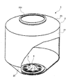
- FIG. 1 It is a schematic block diagram of the pulper which has the rotor blade part (blade blade) of this invention. It is a partial sectional view. It is an enlarged view of the bottom part of a pulper.
- (A) is a top view
- (b) is a cross-sectional schematic diagram. It is a perspective view of a blade blade part. In addition, the concave streak is partially seen through.
- It is sectional drawing of a blade blade and a strainer. It is sectional drawing of the conventional blade blade.
- (A) is a sectional view of one replaceable blade type
- (b) is a sectional view of two replaceable blade types
- (c) is a plan view of a rotor equipped with the replaceable blade type of (b). Yes (the strainer is also shown).
- FIG. 1 is a schematic configuration diagram of a pulper having a rotor blade portion of the present invention.
- FIG. 2 is an enlarged view of the bottom portion of the pulper.
- FIG. 3 is a perspective view of the blade blade portion.
- FIG. 4 is a cross-sectional view of the blade blade and the strainer.
- the pulper 1 includes a storage tank 2, a strainer 3 provided at the bottom of the storage tank 2, and a rotor 4 that rotates on the strainer 3.
- the storage tank 2 includes a cylindrical portion 21, a truncated cone portion 22 that faces the rotor 4, and an upper lid 23.
- the upper lid 23 has an insertion port 231 through which used paper or the like is inserted.
- a water supply pipe is joined to the cylindrical portion 21.
- the mixture of water and waste paper gathers in the rotor 4 due to the slope of the truncated cone portion 22, and efficient shearing is realized. In other words, rapid slurrying of the mixture is achieved.
- the strainer 3 is a plate-like member having a predetermined thickness in which a large number of holes 31 are formed, and shears waste paper with the holes 31 and the blade blades 5 of the rotor 4 described later.
- stainless steel having a predetermined hardness is used for the strainer 3.
- An openable / closable discharge port (not shown) is provided directly below the strainer 3 to discharge the slurry in an appropriate state.
- the rotor 4 is generally disc-shaped, and includes a rotor body 41 and a rotor cap 42 that is attached to the upper portion of the rotor body 41 and rotates integrally with the rotor body 41.
- both the rotor body 41 and the rotor cap 42 are made of stainless steel having a predetermined hardness or strength.
- the rotor body 41 is provided with eight blade blades 5 arranged in a rotationally symmetrical manner extending in the radial direction with respect to the rotation axis.
- the blade blade 5 is configured by covering a base portion 51 with a substantially U-shaped recess 52.
- the base portion 51 is an extended portion of the rotor body 41, and the front side in the rotational direction of the rotor 4 is formed in a protruding line.
- the concave stripe 52 has a shape that fits into the convex stripe, and is divided into two along the longitudinal direction, and an L-shaped blade body 521 positioned on the rotor 4 upper surface side and a plate blade positioned on the rotor 4 bottom surface side (strainer 3 side). And a body 522.
- the L-shaped blade body 521 and the plate blade body 522 are formed by tightening bolts B from the upper surface side of the rotor 4 through holes 511 passing through the upper and lower ridges lying on the side. It joins to the part 51 (it will be in the state which the groove 52 covered the protrusion).
- the plate blade body 522 is a substantially rectangular plate material having a predetermined thickness, and uses a specific high hardness stainless steel.
- the L-shaped blade body 521 is a columnar body having an L-shaped cross section, and uses a predetermined high hardness stainless steel.
- the concave strip 52 has a front surface S in the rotational direction forming a front inclined surface, and waste paper or slurry is guided to the strainer 3 side, thereby increasing the shear efficiency.
- the corners 521C and 522C gradually wear with use.
- the strainer 3 exists immediately below, the resistance increases and the wear rate is fast (if the material is the same, the corner 522C wears out at a rate three times the wear rate of the corner 521C. To go). Therefore, in the blade blade 5, the L-shaped blade body 521 uses a material with a hardness higher than that of the base portion 51, and the plate blade body 522 uses a material with a hardness higher than that of the L-shaped blade body 521. Thereby, the lifetime of the corner 522C can be extended, and the maintainability is improved.
- the plate blade body 522 is plate-shaped and therefore excellent in workability.
- the volume of the plate blade body 522 is smaller than that of the L-shaped blade body 521 and the running cost is also reduced. Even when compared with the conventional two-blade configuration shown in FIG. 5B, the volume of the plate blade body 522 is 1/2 to 1/3 of the replacement blade on the lower side of the figure, which is economical.
- the concave strip 52 can be easily fitted to the base portion 51 using an electric tool. Since it can be detached, it is extremely easy to replace. Note that the number of bolts B can also be half that of the two-blade specification shown in FIG. 5B (see FIG. 5C).
- a reinforcing plate 53 is welded to the bottom surface of the blade blade 5.
- the reinforcing plate 53 uses the same material as the L-shaped blade body 521. Thereby, the lifetime of the rotor 4 is further improved.
- the rotor cap 42 is formed by a substantially conical cap base 421 that rises in a mountain shape, and a plurality of stirring protrusions 422 that are radially provided so as to form convex ridges that draw an arc on the upper surface of the cap base 421.
- the cap base 421 and the stirring protrusion 422 are integrated.
- the stirring blade 512 On the upper surface of the blade blade 5, ridges that form a smooth arc continuous with the stirring protrusion 422 are formed as the stirring blade 512.
- the stirring blade 512 is away from the center of rotation and has a high speed to shear the used paper again. Like the concave strip 52, it is worn by resistance, so that the stirring blade 512 is also replaceable. That is, it is possible to attach and detach with a power tool from above with the bolt B.
- waste paper is introduced from the input port 231 with the discharge port of the storage tank 2 closed, and then water is poured. Then, the rotor 4 is rotated. As the rotor 4 rotates, a water flow that circulates in the storage tank 2 is generated, and the waste paper is sequentially refined by the blade blade 5. Thereafter, the discharge port is opened, and the pulp-containing liquid (slurry) is taken out.
- the pulper 1 is a pulper that employs an economical replacement blade structure that is excellent in wear resistance and workability.
- the present invention is not limited to the above embodiment.
- the number of blade blades 5 is not eight, but may be six or ten.
- the rotor cap 42 is not limited to the mountain shape but may be a shape that rises like a bowl.
- the reinforcing plate 53 may also be exchangeable.
- This rotor structure can be used in the field of stirring / dissolving or stirring shearing.
Landscapes
- Engineering & Computer Science (AREA)
- Life Sciences & Earth Sciences (AREA)
- Wood Science & Technology (AREA)
- Mechanical Engineering (AREA)
- Paper (AREA)
Abstract
Priority Applications (3)
| Application Number | Priority Date | Filing Date | Title |
|---|---|---|---|
| KR1020177037290A KR102017723B1 (ko) | 2015-07-14 | 2016-03-17 | 펄퍼 및 펄퍼 로터의 날부 구조 |
| CN201680040911.4A CN107849809B (zh) | 2015-07-14 | 2016-03-17 | 碎浆机以及转子刃部 |
| JP2017528296A JP6945449B2 (ja) | 2015-07-14 | 2016-03-17 | パルパーおよびパルパーロータの刃部構造 |
Applications Claiming Priority (2)
| Application Number | Priority Date | Filing Date | Title |
|---|---|---|---|
| JP2015140196 | 2015-07-14 | ||
| JP2015-140196 | 2015-07-14 |
Publications (1)
| Publication Number | Publication Date |
|---|---|
| WO2017010123A1 true WO2017010123A1 (fr) | 2017-01-19 |
Family
ID=57758079
Family Applications (1)
| Application Number | Title | Priority Date | Filing Date |
|---|---|---|---|
| PCT/JP2016/058422 Ceased WO2017010123A1 (fr) | 2015-07-14 | 2016-03-17 | Désintégrateur et structure de lame pour rotor de désintégrateur |
Country Status (5)
| Country | Link |
|---|---|
| JP (1) | JP6945449B2 (fr) |
| KR (1) | KR102017723B1 (fr) |
| CN (1) | CN107849809B (fr) |
| TW (1) | TWI609113B (fr) |
| WO (1) | WO2017010123A1 (fr) |
Cited By (1)
| Publication number | Priority date | Publication date | Assignee | Title |
|---|---|---|---|---|
| CN107916592A (zh) * | 2017-12-14 | 2018-04-17 | 济南大学 | 一种扰流板组合且截面多变式碎浆机 |
Citations (3)
| Publication number | Priority date | Publication date | Assignee | Title |
|---|---|---|---|---|
| JPH02147241U (fr) * | 1989-05-16 | 1990-12-13 | ||
| JP2009287131A (ja) * | 2008-05-27 | 2009-12-10 | Rootaa Kogyo Kk | パルパー製造装置用のロータ及びそのようなロータを備えるパルパー装置 |
| JP2014005570A (ja) * | 2012-06-26 | 2014-01-16 | Aikawa Iron Works Co Ltd | パルパー |
Family Cites Families (16)
| Publication number | Priority date | Publication date | Assignee | Title |
|---|---|---|---|---|
| US3707267A (en) * | 1971-02-24 | 1972-12-26 | Beloit Corp | Replaceable vane insert for impeller |
| JPS5982491A (ja) * | 1982-10-28 | 1984-05-12 | 株式会社岩科製作所 | 離解機 |
| US5086209A (en) * | 1988-02-16 | 1992-02-04 | The Mead Corporation | Hot air apparatus for glossing sheets |
| JPH0738292U (ja) * | 1993-12-27 | 1995-07-14 | 日本車輌製造株式会社 | オーガドリルの掘削刃取付構造 |
| DE19649764C2 (de) * | 1995-12-02 | 2000-11-30 | Ask High Technology Tech Entwi | Vorrichtung zum Zerkleinern von Material, insbesondere von Altpapier |
| DE19850204A1 (de) * | 1998-10-23 | 2000-04-27 | Bech Ulrich | Modular aufgebauter Rotor mit wechselbaren, gepanzerten Arbeitskanten für die Stoffaufbereitung |
| JP4691427B2 (ja) * | 2005-09-22 | 2011-06-01 | ローター工業株式会社 | パルパー |
| JP2007138354A (ja) * | 2005-11-21 | 2007-06-07 | Mitsubishi Heavy Ind Ltd | 紙料離解装置 |
| JP4934881B2 (ja) * | 2007-05-23 | 2012-05-23 | ボイス パテント ゲーエムベーハー | 古紙裁断用ロータ |
| DE102009012236A1 (de) * | 2009-03-07 | 2010-09-09 | Voith Patent Gmbh | Rotorverschleißschutz |
| WO2012041269A2 (fr) * | 2010-09-17 | 2012-04-05 | Hans-Joachim Boltersdorf | Désintégrateur pourvu d'une plaque de tamisage |
| DE102011012191A1 (de) * | 2010-10-05 | 2012-04-05 | Hans-Joachim Boltersdorf | Verfahren zur Aufbereitung von Grünschnitt |
| DE102011082976A1 (de) * | 2011-09-19 | 2013-03-21 | Günter Betz | Vorrichtung zum Aufschlagen (zerkleinern, zerfasern, auflösen, aufbereiten) von Altpapieren und Zellstoffen in einem Pulper (Stofflöser) |
| JP5438813B2 (ja) | 2012-10-12 | 2014-03-12 | ローター工業株式会社 | パルパー製造装置用のロータ及びそのようなロータを備えるパルパー装置 |
| CN203654072U (zh) * | 2013-12-26 | 2014-06-18 | 山东杰锋机械制造有限公司 | 轻渣分离机叶轮 |
| CN204370227U (zh) * | 2014-11-29 | 2015-06-03 | 中冶纸业银河有限公司 | 一种新型防堵塞水力碎浆机飞刀转子 |
-
2016
- 2016-03-17 WO PCT/JP2016/058422 patent/WO2017010123A1/fr not_active Ceased
- 2016-03-17 KR KR1020177037290A patent/KR102017723B1/ko active Active
- 2016-03-17 JP JP2017528296A patent/JP6945449B2/ja not_active Expired - Fee Related
- 2016-03-17 CN CN201680040911.4A patent/CN107849809B/zh active Active
- 2016-07-11 TW TW105121665A patent/TWI609113B/zh active
Patent Citations (3)
| Publication number | Priority date | Publication date | Assignee | Title |
|---|---|---|---|---|
| JPH02147241U (fr) * | 1989-05-16 | 1990-12-13 | ||
| JP2009287131A (ja) * | 2008-05-27 | 2009-12-10 | Rootaa Kogyo Kk | パルパー製造装置用のロータ及びそのようなロータを備えるパルパー装置 |
| JP2014005570A (ja) * | 2012-06-26 | 2014-01-16 | Aikawa Iron Works Co Ltd | パルパー |
Cited By (1)
| Publication number | Priority date | Publication date | Assignee | Title |
|---|---|---|---|---|
| CN107916592A (zh) * | 2017-12-14 | 2018-04-17 | 济南大学 | 一种扰流板组合且截面多变式碎浆机 |
Also Published As
| Publication number | Publication date |
|---|---|
| KR20180012319A (ko) | 2018-02-05 |
| TW201702459A (zh) | 2017-01-16 |
| JPWO2017010123A1 (ja) | 2018-07-12 |
| CN107849809A (zh) | 2018-03-27 |
| CN107849809B (zh) | 2019-11-26 |
| TWI609113B (zh) | 2017-12-21 |
| KR102017723B1 (ko) | 2019-09-03 |
| JP6945449B2 (ja) | 2021-10-06 |
Similar Documents
| Publication | Publication Date | Title |
|---|---|---|
| TWI564079B (zh) | 粉碎機及其刀具組與其刀具 | |
| CN102271847B (zh) | 用于去屑加工的旋转刀具及用于该刀具的切削刀片 | |
| US11794194B2 (en) | Shredder blade assembly | |
| FI120774B (fi) | Seulova, murskaava tai sekoittava kauha | |
| US8186611B1 (en) | Segmented knife assembly with replaceable wear segments | |
| JP5793557B2 (ja) | 耐摩耗ライニングを有する混合装置 | |
| RU2592561C2 (ru) | Держатель изнашиваемого наконечника для ударной дробилки с вертикальным валом, комплект, содержащий держатель изнашиваемого наконечника, и способ уменьшения скорости износа держателя изнашиваемого наконечника | |
| JP5203802B2 (ja) | パルパー製造装置用のロータ及びそのようなロータを備えるパルパー装置 | |
| US20110204171A1 (en) | Replaceable insert for a hammermill hammer | |
| CN103511331A (zh) | 离心泵 | |
| CN102689045B (zh) | 多刀头开槽刀具 | |
| JP5979054B2 (ja) | ドリル用インサートおよび刃先交換式ドリル | |
| JP5023655B2 (ja) | 切削工具 | |
| JP5438813B2 (ja) | パルパー製造装置用のロータ及びそのようなロータを備えるパルパー装置 | |
| JPWO2017010123A1 (ja) | パルパーおよびパルパーロータの刃部構造 | |
| CN201906630U (zh) | 立式冲击破的圆叶轮 | |
| JP6013373B2 (ja) | 切削工具および切削工具用の締付け凹部を有する切削インサート | |
| CN104707695B (zh) | 一种粉碎机 | |
| CN206567044U (zh) | 一种用于破碎机的刀片架安装机构 | |
| CN211200012U (zh) | 一种高性能路面铣刨齿 | |
| CN210412737U (zh) | 一种高进给多刃铣刀盘 | |
| CN205255214U (zh) | 一种用于加工板式家具的修边刀 | |
| JP5028672B2 (ja) | 古紙裁断用ロータ | |
| CN202639454U (zh) | 多刀头开槽刀具 | |
| CN209831296U (zh) | 一种改进型研磨轮磨块 |
Legal Events
| Date | Code | Title | Description |
|---|---|---|---|
| 121 | Ep: the epo has been informed by wipo that ep was designated in this application |
Ref document number: 16824104 Country of ref document: EP Kind code of ref document: A1 |
|
| ENP | Entry into the national phase |
Ref document number: 20177037290 Country of ref document: KR Kind code of ref document: A |
|
| NENP | Non-entry into the national phase |
Ref country code: DE |
|
| ENP | Entry into the national phase |
Ref document number: 2017528296 Country of ref document: JP Kind code of ref document: A |
|
| 122 | Ep: pct application non-entry in european phase |
Ref document number: 16824104 Country of ref document: EP Kind code of ref document: A1 |