WO2017010146A1 - Joint d'étanchéité annulaire sans contact et machine rotative le comportant - Google Patents
Joint d'étanchéité annulaire sans contact et machine rotative le comportant Download PDFInfo
- Publication number
- WO2017010146A1 WO2017010146A1 PCT/JP2016/063529 JP2016063529W WO2017010146A1 WO 2017010146 A1 WO2017010146 A1 WO 2017010146A1 JP 2016063529 W JP2016063529 W JP 2016063529W WO 2017010146 A1 WO2017010146 A1 WO 2017010146A1
- Authority
- WO
- WIPO (PCT)
- Prior art keywords
- pressure side
- thread groove
- cross
- annular seal
- contact annular
- Prior art date
- Legal status (The legal status is an assumption and is not a legal conclusion. Google has not performed a legal analysis and makes no representation as to the accuracy of the status listed.)
- Ceased
Links
Images















Classifications
-
- F—MECHANICAL ENGINEERING; LIGHTING; HEATING; WEAPONS; BLASTING
- F04—POSITIVE - DISPLACEMENT MACHINES FOR LIQUIDS; PUMPS FOR LIQUIDS OR ELASTIC FLUIDS
- F04D—NON-POSITIVE-DISPLACEMENT PUMPS
- F04D29/00—Details, component parts, or accessories
- F04D29/08—Sealings
- F04D29/16—Sealings between pressure and suction sides
-
- F—MECHANICAL ENGINEERING; LIGHTING; HEATING; WEAPONS; BLASTING
- F16—ENGINEERING ELEMENTS AND UNITS; GENERAL MEASURES FOR PRODUCING AND MAINTAINING EFFECTIVE FUNCTIONING OF MACHINES OR INSTALLATIONS; THERMAL INSULATION IN GENERAL
- F16J—PISTONS; CYLINDERS; SEALINGS
- F16J15/00—Sealings
- F16J15/44—Free-space packings
Definitions
- the present invention relates to a non-contact annular seal and a rotary machine including the same, and in particular, a fluid between an impeller and a casing in a rotary machine that handles a liquid such as water or oil, in other words, an incompressible fluid.
- the present invention relates to a non-contact annular seal that reduces the amount of leakage, reduces vibration, and exhibits stable shaft sealing characteristics, and a rotary machine including the same.
- Rotating machines that transfer liquids are widely used in plants or facilities for power generation, chemical processes, sewerage, waterworks, and the like.
- the pump has a casing and a rotating shaft on which an impeller is mounted.
- a rotating shaft is arrange
- the liquid sucked from the suction port of the casing is pressurized by the rotation of the impeller and discharged from the discharge port of the casing. That is, in the flow path inside the pump, a high pressure region and a low pressure region are formed, and fluid flows from the high pressure region to the low pressure region.
- the non-contacting annular seal is used in the part circled in the figure. That is, it is used between the inlet part of the impeller, between the front stage impeller and the rear stage impeller, between the last stage impeller outlet part and the low pressure side, and the like.
- the differential pressure is large between the impeller outlet and the low pressure side, and fluid leakage is large, the fluid leakage at this portion has a great influence on the pump performance.
- non-contact annular seals of various structures that can reduce the amount of fluid leakage are known.
- the smooth seal is known as the most basic non-contact annular seal.
- the smooth seal is a seal formed by arranging double cylinders having smooth surfaces.
- a non-contact annular seal such as a smooth seal
- it is effective to reduce the radial gap between the rotating side and the stationary side of the non-contact annular seal.
- the radial gap cannot be made extremely small.
- a non-contact annular seal that reduces the leakage amount without reducing the radial gap is required.
- a parallel groove seal, a damper seal, a thread groove seal and the like are known.
- an example of a conventional non-contact annular seal will be described.
- FIG. 14 is a partial cross-sectional view of a conventional parallel groove seal.
- the parallel groove seal 111 includes a rotating shaft 121 that is a rotating body having a smooth outer peripheral surface, and a fixed body 131 in which a plurality of concentric grooves 141 are provided on a surface facing the rotating shaft 121.
- This parallel groove seal 111 has energy loss due to vortices generated when the fluid flowing through the gap between the rotating shaft 121 and the fixed body 131 passes through the groove 141, pressure loss caused by sudden expansion and contraction of the flow path, and the like. Thus, the leakage amount (movement amount) of the fluid can be reduced.
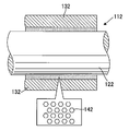
- FIG. 15 and 16 are partial cross-sectional views of a conventional damper seal.
- FIG. 15 shows a damper seal that employs a honeycomb pattern as a damper structure.
- the fixed body 132 is shown in a sectional view
- the rotating shaft 122 is shown in a side view.
- the damper seal 112 includes a rotating shaft 122 that is a rotating body having a smooth outer peripheral surface, and a fixed body 132 having a plurality of concave portions 142 provided on a surface facing the rotating shaft 122.
- a hexagonal honeycomb pattern is used as the recess 142.
- the damper seal 112 can reduce the amount of fluid leakage due to the pressure loss of the fluid generated when the fluid flowing through the gap between the rotating shaft 122 and the fixed body 132 flows through the recess 142.
- FIG. 16 shows a damper seal that employs a hole pattern as a damper structure.
- the fixed body 133 is shown in a sectional view
- the rotating shaft 123 is shown in a side view.
- the damper seal 113 includes a rotating shaft 123 that is a rotating body having a smooth outer peripheral surface, and a fixed body 133 that is provided with a plurality of recesses 143 on a surface facing the rotating shaft 123.
- a circular concave hole pattern is used as the concave portion 143.
- the damper seal 113 can reduce the amount of fluid leakage due to the pressure loss of the fluid that occurs when the fluid flowing through the gap between the rotating shaft 123 and the fixed body 133 flows through the recess 143.
- FIG. 17 is a partial sectional view of a conventional thread groove seal.
- the fixed body 134 is shown in a sectional view
- the rotating shaft 124 is shown in a side view.
- the thread groove seal 114 includes a cylindrical fixed body 134 having a smooth inner peripheral surface, and a rotating shaft 124 having a thread groove 144 formed on a surface facing the fixed body 134.
- the thread groove seal 114 can push the fluid back to the high pressure side by the pumping effect according to the rotation direction, and can greatly reduce the amount of leakage. Since the thread groove seal 114 can push the fluid back to the high pressure side by the pumping effect, the leakage of the fluid can be particularly reduced when sealing an incompressible fluid that is a liquid such as water.
- the pumping effect of the thread groove seal 114 is affected by the size of the lead angle ⁇ of the thread groove 144. That is, if the lead angle ⁇ is small, the pumping effect is small, and if the lead angle ⁇ is large, the pumping effect is large.
- the lead angle ⁇ in the rotary shaft 124 having a predetermined diameter, the fixed body 134 having a predetermined inner diameter, and the thread groove seal 114 having a predetermined groove pitch it is necessary to increase the number of thread grooves. There is.
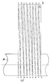
- FIG. 18 and FIG. 19 are schematic views in which a single thread and a four thread are developed, respectively.
- the number of screw grooves in the axial direction is eight, and the groove interval (pitch) in the axial direction is ⁇ .
- the shaft diameter is D1
- the developed lateral length is D1 ⁇ ⁇
- the longitudinal length is an arbitrary length L. Therefore, the developed part becomes substantially rectangular.
- FIG. 18 is a schematic diagram of a single thread.
- the interval (pitch) of the grooves in the axial direction is ⁇ and reaches eight times around the upper end H of the thread groove.
- the lead angle is ⁇ .
- FIG. 19 is a schematic view of a 4-thread screw. Since there are four starting points of the thread groove every 90 degrees in the radial direction, the flow path is four times as large as the groove of the single thread. Proceeding upward along the screw groove starting from 0 degrees below the left end, it reaches D on the right side, but since it has made one round of the axis here, the continuation of the groove moves to D on the left side. Proceeding further from D on the left side, it reaches the upper end H of the thread groove on the right side. The same is true for the three threaded grooves starting from other angles. In other words, the screw groove reaches the upper end after two rounds. Further, the lead angle of the four-thread screw shown in FIG. 19 is ⁇ .
- the pumping performance by the thread groove depends on how much the medium in the thread groove can be moved in the axial direction by one rotation. Therefore, under the same groove width, depth, and pitch conditions, the larger the lead angle, the greater the amount of movement in the axial direction per rotation. As shown in FIGS. 18 and 19, the lead angle ⁇ of the single thread is smaller than ⁇ of the four thread. And the four-thread screw is superior to the one-thread screw in pumping performance per groove.
- the number of screw grooves becomes four times, and in this case, the cross-sectional area of the screw groove 144 increases as the number of thread grooves increases.
- the amount of leakage flowing from the high pressure side to the low pressure side increases.
- the amount of leakage that increases due to an increase in the cross-sectional area of the screw groove 144 is greater than the amount of leakage that is reduced by the pumping effect, resulting in an increase in the overall amount of leakage.
- the thread groove seal 144 has a problem that a trade-off relationship exists between the pumping effect and the cross-sectional area of the thread groove 144.
- FIG. 20 is a schematic partial cross-sectional view of a conventional thread groove seal in which the thread groove is formed on the stationary side.
- the fixed body 134 is shown in a sectional view
- the rotating shaft 124 is shown in a side view.
- the thread groove seal 115 includes a rotating shaft 124 that is a rotating body having a smooth outer peripheral surface, and a fixed body 134 that has a thread groove 144 formed on a surface facing the rotating shaft 124.
- the thread groove seal 115 shown in FIG. 20 also improves the pumping effect when the lead angle is increased, as in the thread groove seal 114 shown in FIG. 17, but the cross-sectional area of the thread groove 144 increases. As a result, the overall leakage amount may increase.
- Patent Document 1 Japanese Utility Model Publication No. 62-98798 (Patent Document 1) and Japanese Utility Model Application Publication No. 62-101093 (Patent Document 2), in the thread groove seal portion, the screw depth and the screw depth from the high pressure side to the low pressure side.
- a sealing technique is disclosed in which the thread cross-sectional area depending on the width and width is increased continuously or stepwise.
- the thread groove seal with such a configuration has a certain sealing effect for fluids under atmospheric pressure such as air, but in the case of incompressible fluid such as water, the cross-sectional area of the seal channel is downstream. As the width becomes larger, the flow in the thread groove seal becomes unstable, which may adversely affect the shaft runout.
- the present invention has been made in view of the above-described conventional problems, and one of its purposes is to increase the lead angle in order to effectively use the leakage reduction effect due to the pumping effect of the thread groove seal.
- the purpose is to reduce the influence of the increase in leakage amount. In other words, increasing the lead angle (increasing the number of thread grooves) maximizes the pumping effect of the thread groove seal and reduces the amount of leakage associated therewith.
- Another object of the present invention is to provide a thread groove seal that can stabilize the flow in the thread groove seal and can rotate the shaft stably.
- Another object of the present invention is a rotating machine that rotates a rotating shaft to which an impeller is attached to transfer a fluid, and reduces the leakage of fluid pressurized by the impeller to the low pressure side. It is to provide a rotating machine that increases pump efficiency.
- the non-contact annular seal concerning the 1st form of the present invention has a rotating body provided in a rotating part of a rotating machine, and a fixed body provided in a fixing part of the rotating machine, and the rotating body and the fixed A non-contact annular seal configured to seal a fluid flowing through a gap between the body and a screw groove provided on at least one of the surface of the rotating body and the surface of the fixed body that forms the gap.
- the screw groove has a region in which the cross-sectional area of the screw groove on the high-pressure side is larger than the cross-sectional area of the screw groove on the low-pressure side, and the number of the thread grooves is four or more.
- the non-contact annular seal according to a second aspect of the present invention is the non-contact annular seal according to the first aspect, wherein the region has a continuous cross-sectional area of the thread groove from the high pressure side toward the low pressure side. A reduced region formed to be smaller.
- the non-contact annular seal according to a third aspect of the present invention is the non-contact annular seal according to the second aspect, wherein the reduced region has a depth of the thread groove from the seal inlet side toward the seal outlet side. Has a region formed so as to be continuously reduced.
- a non-contact annular seal according to a fourth aspect of the present invention is the non-contact annular seal according to the second or third aspect, wherein the reduced region has a width of the thread groove from the high pressure side toward the low pressure side. Has a region formed so as to be continuously reduced.
- a non-contact annular seal according to a fifth aspect of the present invention is the non-contact annular seal according to any one of the second to fourth aspects, wherein the reduced area has a constant ratio of the depth and width of the thread groove. It has the area
- a non-contact annular seal according to a sixth aspect of the present invention is the non-contact annular seal according to the first aspect, wherein the area of the region gradually decreases from the high pressure side toward the low pressure side. Having a reduced region formed on the substrate.
- the non-contact annular seal according to a seventh aspect of the present invention is the non-contact annular seal according to the sixth aspect, wherein the reduced region has a stepped depth of the thread groove from the high pressure side toward the low pressure side. A region formed so as to be smaller.
- a rotating machine includes an electric motor, a main shaft that is connected to the electric motor and configured to be rotatable, and an impeller that is fitted to the main shaft and configured to be rotatable together with the main shaft.
- the portion and the fixing portion have the non-contact annular seal described in any one of the first to seventh embodiments.
- a non-contact annular seal having a thread groove even if the lead angle of the thread groove is increased (increasing the number of thread grooves) to increase the pumping effect, the screw The cross-sectional area of the groove becomes smaller when considered in the average of the axial direction of the seal, and the leakage amount can be greatly reduced.
- a non-contact seal having high shaft sealing performance can be realized without reducing the radial clearance of the non-contact seal.
- a rotary machine that rotates a rotating shaft to which an impeller is attached and transfers a fluid, and reduces the leakage of fluid pressurized by the impeller to the low pressure side.
- a rotating machine that increases efficiency can be provided.
- FIG. 6 is a graph showing simulation results of Experimental Example 1 and Comparative Example 1. It is a graph which shows the simulation result of Experimental example 2 and Comparative example 2.
- FIG. 6 is a fragmentary sectional view of the conventional parallel groove seal.
- FIG. 6 is a partial cross-sectional view showing a conventional damper seal that employs a honeycomb pattern.
- FIG. 1 is a cross-sectional view of a high-pressure pump (multistage centrifugal pump) that is a rotary machine to which the non-contact annular seal according to the present embodiment can be applied.
- the high-pressure pump 1 includes a main shaft 11 that is connected to an electric motor (not shown) and rotates, impellers 21a, 21b, and 21c fitted to the main shaft 11, a casing 31 that houses the impellers 21a, 21b, and 21c, and a casing. And bearings 45a and 45b attached to 31.
- the bearings 45a and 45b support the main shaft 11 to be rotatable.
- An electric motor (not shown) for rotationally driving the high-pressure pump 1 is connected to the main shaft 11 via a coupling 13 fitted to the left end of the main shaft 11.
- the casing 31 has a suction port 33 for sucking a fluid, that is, a liquid such as water from the outside, and a discharge port 37 for discharging the sucked fluid.
- the first stage impeller 21 a fitted to the main shaft 11 rotates as the main shaft 11 rotates, and sucks fluid into the casing 31 from the suction port 33.
- the fluid sucked and pressurized by the first stage impeller 21a passes through the first flow path 35a and reaches the second stage impeller 21b.
- the fluid pressurized by the second stage impeller 21b passes through the second flow path 35b and reaches the third stage impeller 21c.
- the fluid is further pressurized by the third stage impeller 21c, discharged from the discharge port 37, and transferred through a pipe (not shown). That is, the fluid is pressurized by the first stage impeller 21a, the second stage impeller 21b, and the third stage impeller 21c.
- the non-contact annular seal of this embodiment reduces the leakage.
- the non-contact annular seal of this embodiment is provided at a site surrounded by a circle. Since the high-pressure pump 1 shown in FIG. 1 is a multi-stage centrifugal pump, the fluid pressure is higher than that of a single-stage centrifugal pump, and the amount of fluid leakage inevitably increases. If the amount of leakage is large, the pump efficiency decreases.
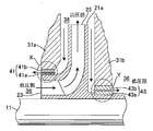
- FIG. 2 is an enlarged cross-sectional view of the first stage impeller 21a of the high-pressure pump 1 shown in FIG.
- the first stage impeller 21a includes a suction port 23 for sucking fluid and a discharge port 25 for discharging fluid.
- the pressure of the fluid is low on the suction port 23 side and high on the discharge port 25 side. That is, the suction port 23 is a low pressure part 36, and the discharge port 25 is a high pressure part 38.
- the fluid leaking portion in the high-pressure pump 1 is mainly a facing portion X between the outer peripheral surface of the suction port 23 and the casing 31a, and a facing portion Y between the outer peripheral surface of the rear surface of the impeller 21a and the casing 31b.
- Non-contact annular seals 41 and 43 according to the present embodiment are provided in the gaps formed in the facing portions X and Y, respectively.
- non-contact annular is formed in the gap between the impeller 21a as the rotating part and the casings 31a and 31b as the fixing parts. Seals 41 and 43 are provided to narrow the gap.
- the thread groove seal is an excellent seal structure that can reduce the amount of leakage due to the pumping effect of the thread groove, and when the screw groove is provided on the rotating side or the screw groove is provided on the stationary side.
- the non-contact annular seals 41 and 43 include rotating bodies 41a and 43a provided on the impeller 21a that is a rotating part of the high-pressure pump 1, and fixed bodies 41b and 43b provided on the casings 31a and 31b that are fixed parts.
- the rotating bodies 41a and 43a are provided as members different from the impeller 21a, but the rotating bodies 41a and 43a may be formed integrally with the impeller 21a.
- the fixed bodies 41b and 43b are provided as members different from the casings 31a and 31b in the illustrated example, the fixed bodies 41b and 43b may be formed integrally with the casings 31a and 31b.
- FIG. 3 is a partial cross-sectional view showing the non-contact annular seal of this embodiment applicable to the non-contact annular seals 41 and 43 shown in FIG.
- the fixed body 136 is shown in a sectional view
- the rotating body 126 is shown in a side view.
- the non-contact annular seal 116 of the present embodiment is provided on the rotating body 126 provided on the impeller 21a that is the rotating part shown in FIG. 2 and the casings 31a and 31b that are the fixing parts shown in FIG. And a fixed body 136 to be provided.
- the rotating body 126 is configured to rotate together with the impeller 21a, and includes a screw groove 146 formed in a spiral shape on the surface thereof. That is, the non-contact annular seal 116 of this embodiment is a thread groove seal.
- the fixed body 136 is formed in a substantially cylindrical shape.
- the rotating body 126 is a substantially cylindrical member having an outer diameter smaller than the inner diameter of the fixed body 136.
- the rotating body 126 is disposed inside the fixed body 136 so as to have a predetermined gap with respect to the inner surface of the fixed body 136.
- the fluid passes through the gap between the fixed body 136 and the rotating body 126 from the high pressure side 155 (seal inlet side) to the low pressure side 156 (seal outlet). Side), that is, in the direction of arrow A in the figure.
- the rotating body 126 can push the leaking fluid back to the high pressure side by the pumping effect by rotating in a predetermined direction around the rotating shaft 151.
- FIG. 4 is a partial cross-sectional view of the non-contact annular seal 116 of FIG. 3 cut along the rotating shaft 151.
- the thread groove 146 shown in FIG. 3 will be described in detail with reference to FIG.
- the rotating body 126 has a screw groove 146 and a screw thread 157 formed on the surface thereof in a spiral shape with a predetermined lead angle ⁇ .
- the fixed body 136 and the rotating body 126 are spaced apart so as to have a predetermined gap G.
- the gap G refers to the shortest distance between the inner surface of the fixed body 136 and the top portion (land portion 157a) of the screw thread 157.
- the screw groove 146 has a predetermined screw groove width W and screw groove depth D.
- the thread groove width W is the length of the straight line connecting the adjacent land parts 157a in the shortest, and the screw groove depth D is drawn from the straight line connecting the adjacent land parts 157a to the bottom of the screw groove 146. This is the longest distance of vertical lines.
- the cross-sectional area 158 (seal gap cross-sectional area) of the screw groove 146 is an area surrounded by the shortest straight line of the adjacent land portions 157a and the outer portion forming the screw groove 146 (a region indicated by a hatched portion in the figure). ). That is, the cross-sectional shape of the thread groove 146 of this embodiment is a rectangular shape.
- the thread groove width W is constant over the entire length of the thread groove 146, and the thread groove depth D is equal to the high pressure side 155 (seal inlet). Side) toward the low pressure side 156 (seal outlet side). Accordingly, the thread groove depth D of the thread groove 146 on the high-pressure side 155 is the largest, and the thread groove depth D on the low-pressure side 156 is the smallest. That is, the non-contact annular seal 116 is formed so that the cross-sectional area 158 of the thread groove 146 continuously decreases from the high pressure side 155 toward the low pressure side 156.
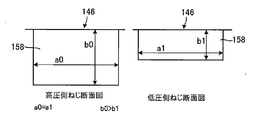
- FIG. 5 is a diagram showing a cross section of the high-pressure side thread groove and a low-pressure side thread groove of the non-contact annular seal 116 of the present embodiment.
- the thread groove cross section on the high pressure side of the thread groove 146 is a rectangular cross section having a width a0 and a depth b0.
- the screw groove cross section on the low pressure side is a rectangular cross section having a width a1 and a depth b1.
- the width a0 is equal to the width a1
- the depth b0 is greater than the depth b1. That is, the thread groove 146 is formed such that the thread groove depth continuously decreases from the high-pressure side toward the low-pressure side while keeping the thread groove width constant.
- the non-contact annular seal 116 is formed so that the cross-sectional area 158 of the thread groove 146 continuously decreases from the high pressure side toward the low pressure side.
- the pumping effect is improved by changing the thread groove depth D to continuously reduce the cross-sectional area 158 of the thread groove 146 from the high pressure side 155 toward the low pressure side 156. Therefore, even if the lead angle ⁇ is increased, the average value of the cross-sectional area 158 in the entire length of the thread groove 146 can be reduced as compared with the case where the cross-sectional area of the thread groove is uniformly large.
- the cross-sectional area at the beginning of the screw groove on the high-pressure side is A and the cross-sectional area at the end of the low-pressure side is B, if the area ratio B / A is 0 ⁇ B / A ⁇ 1, the result is a non-contact annular seal.
- a non-contact annular seal having high shaft sealing performance can be realized without reducing the radial clearance of the non-contact annular seal 116.
- the cross-sectional area of the high-pressure side 155 is large and the cross-sectional area of the low-pressure side 156 is small, the flow in the thread groove seal is stabilized, and the shaft can rotate stably.
- the cross-sectional area 158 of the screw groove 146 is formed so as to decrease from the high pressure side 155 toward the low pressure side 156 over the entire length of the screw groove 146.
- the screw groove 146 is formed so that the cross-sectional area 158 has a region that decreases from the high pressure side 155 toward the low pressure side 156 in at least a part of the entire length of the screw groove 146, the same effect can be obtained. Can do.
- the screw groove 146 is formed in the rotating body 126, but instead, the screw groove 146 may be provided on the inner surface of the fixed body 136 as shown in FIG.
- FIG. 6 is a view showing a non-contact annular seal 117 in which a thread groove 146 is provided on the inner surface of the fixed body 136.
- the fixed body 136 has a thread groove 146 on its inner surface.
- the depth of the thread groove 146 is formed so as to decrease from the high pressure side 155 toward the low pressure side 156. That is, the cross-sectional area of the thread groove 146 is formed so as to decrease from the high pressure side 155 toward the low pressure side 156.
- the cross-sectional area of the screw groove 146 is formed so as to decrease from the high-pressure side 155 toward the low-pressure side 156, the average value of the cross-sectional areas in the entire length of the screw groove 146 can be reduced. As a result, the flow rate of fluid leaking from the non-contact annular seal 117 can be reduced.
- a thread groove 146 may be provided in both the rotating body 126 and the fixed body 136.
- the thread groove 146 of the non-contact annular seal described above has a rectangular cross section and is formed so that the thread groove depth decreases from the high pressure side 155 toward the low pressure side 156.
- the cross-sectional shape of the thread groove 146 is not limited to this.
- the cross-sectional shape shown in FIGS. 7 to 10 described below may be used.
- FIG. 7A and 7B are views showing a cross section on the high pressure side and a cross section on the low pressure side of the thread groove having a rectangular cross section.
- the screw groove cross section on the high pressure side (seal inlet side) of the screw groove shown in FIG. 7A is a rectangular cross section having a width a0 and a depth b0.
- the thread groove cross section on the low pressure side (seal outlet side) is a rectangular cross section having a width a1 and a depth b1.
- the aspect ratio (a0: b0) of the cross section of the thread groove on the high pressure side is the same as the aspect ratio (a1: b1) of the cross section of the thread groove on the low pressure side.
- the width a0 is larger than the width a1
- the depth b0 is larger than the depth b1. That is, the cross section of the thread groove is formed such that the thread groove width and the thread groove depth are continuously reduced from the high pressure side toward the low pressure side while keeping the aspect ratio constant. Thereby, the thread groove can be formed so that the cross-sectional area of the thread groove continuously decreases from the high pressure side toward the low pressure side.
- the screw groove cross section on the high pressure side (seal inlet side) of the screw groove shown in FIG. 7B is a rectangular cross section having a width a0 and a depth b0.
- the thread groove cross section on the low pressure side (seal outlet side) is a rectangular cross section having a width a1 and a depth b1.
- the width a0 is larger than the width a1
- the depth b0 is equal to the depth b1. That is, the cross section of the thread groove is formed such that the thread groove width continuously decreases from the high pressure side toward the low pressure side while keeping the thread groove depth constant.
- the thread groove can be formed so that the cross-sectional area of the thread groove continuously decreases from the high pressure side toward the low pressure side.
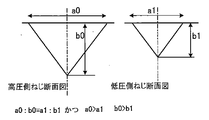
- FIG. 8A to 8C are views showing a cross section on the high pressure side and a cross section on the low pressure side of the thread groove having a triangular cross section.
- the thread groove cross section on the high pressure side (seal inlet side) of the thread groove shown in FIG. 8A is a triangular cross section having a width a0 and a depth b0.
- the thread groove cross section on the low pressure side (seal outlet side) is a triangular cross section having a width a1 and a depth b1.
- the aspect ratio (a0: b0) of the cross section of the thread groove on the high pressure side is the same as the aspect ratio (a1: b1) of the cross section of the thread groove on the low pressure side.
- the width a0 is larger than the width a1
- the depth b0 is larger than the depth b1. That is, the cross section of the thread groove is formed such that the thread groove width and the thread groove depth are continuously reduced from the high pressure side toward the low pressure side while keeping the aspect ratio constant. Thereby, the thread groove can be formed so that the cross-sectional area of the thread groove continuously decreases from the high pressure side toward the low pressure side.
- the screw groove cross section on the high pressure side (seal inlet side) of the screw groove shown in FIG. 8B is a triangular cross section having a width a0 and a depth b0.
- the thread groove cross section on the low pressure side (seal outlet side) is a triangular cross section having a width a1 and a depth b1.
- the width a0 is equal to the width a1
- the depth b0 is greater than the depth b1. That is, the cross section of the thread groove is formed so that the thread groove depth continuously decreases from the high pressure side toward the low pressure side while keeping the thread groove width constant.
- the non-contact annular seal is formed so that the cross-sectional area of the thread groove continuously decreases from the high pressure side toward the low pressure side.
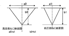
- the thread groove cross section on the high pressure side (seal inlet side) of the thread groove shown in FIG. 8C is a triangular cross section having a width a0 and a depth b0.
- the thread groove cross section on the low pressure side (seal outlet side) is a triangular cross section having a width a1 and a depth b1.
- the width a0 is larger than the width a1
- the depth b0 is equal to the depth b1. That is, the cross section of the thread groove is formed such that the thread groove width continuously decreases from the high pressure side toward the low pressure side while keeping the thread groove depth constant.
- the thread groove can be formed so that the cross-sectional area of the thread groove continuously decreases from the high pressure side toward the low pressure side.
- FIGS. 9A to 9C are views showing a high-pressure side cross-section and a low-pressure side cross-section of a thread groove having a U-shaped cross section.
- the thread groove cross section on the high pressure side (seal inlet side) of the thread groove shown in FIG. 9A is a U-shaped cross section combining a rectangular cross section having a width a0 and a depth b0 and a semicircular cross section having a radius R0. It is.
- the screw groove cross section on the low pressure side (seal outlet side) is a U-shaped cross section that combines a rectangular cross section having a width a1 and a depth b1 and a semicircular cross section having a radius R1.
- the ratio (a0: b0: R0) of the thread groove cross section on the high pressure side is the same as the ratio (a1: b1: R1) of the thread groove cross section on the low pressure side.
- the width a0 is larger than the width a1
- the depth b0 is larger than the depth b1
- the radius R0 is larger than the radius R1. That is, the cross section of the thread groove is formed such that the thread groove width, the thread groove depth, and the thread groove radius are continuously reduced from the high pressure side toward the low pressure side with the ratio being constant. Thereby, the thread groove can be formed so that the cross-sectional area of the thread groove continuously decreases from the high pressure side toward the low pressure side.
- the thread groove cross section on the high pressure side (seal inlet side) of the thread groove shown in FIG. 9B is a U-shaped cross section combining a rectangular cross section having a width a0 and a depth b0 and a semicircular cross section having a radius R0. It is.
- the screw groove cross section on the low pressure side (seal outlet side) is a U-shaped cross section that combines a rectangular cross section having a width a1 and a depth b1 and a semicircular cross section having a radius R1.
- the width a0 is equal to the width a1
- the depth b0 is larger than the depth b1
- the radius R0 is equal to the radius R1.
- the cross section of the thread groove is formed such that the thread groove depth continuously decreases from the high pressure side toward the low pressure side while keeping the thread groove width and the thread groove radius constant.
- the non-contact annular seal is formed so that the cross-sectional area of the thread groove continuously decreases from the high pressure side toward the low pressure side.
- the thread groove cross section on the high pressure side (seal inlet side) of the thread groove shown in FIG. 9C is a U-shaped cross section combining a rectangular cross section having a width a0 and a depth b0 and a semicircular cross section having a radius R0. It is.
- the screw groove cross section on the low pressure side (seal outlet side) is a U-shaped cross section that combines a rectangular cross section having a width a1 and a depth b1 and a semicircular cross section having a radius R1.
- the width a0 is larger than the width a1
- the depth b0 is equal to the depth b1
- the radius R0 is larger than the radius R1.
- the cross section of the thread groove is formed such that the thread groove width and the thread groove radius are continuously reduced from the high pressure side toward the low pressure side while keeping the thread groove depth constant.
- the thread groove can be formed so that the cross-sectional area of the thread groove continuously decreases from the high pressure side toward the low pressure side.
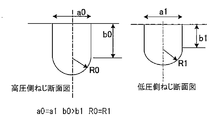
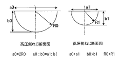
- FIG. 10A and FIG. 10B are views showing a high-pressure side cross-section and a low-pressure side cross-section of a thread groove having a semicircular cross-section.
- the thread groove cross section on the high pressure side (seal inlet side) of the thread groove shown in FIG. 10A is a semicircular cross section having a width a0, a depth b0, and a radius R0.
- the width a0 is equal to twice the radius R0
- the depth b0 is equal to the radius R0.
- the thread groove cross section on the low pressure side (seal outlet side) is a semicircular cross section having a width a1, a depth b1, and a radius R1.
- the width a1 is equal to twice the radius R1, and the depth b1 is equal to the radius R1.
- the ratio (a0: b0) of the thread groove cross section on the high pressure side is the same as the ratio (a1: b1) of the thread groove cross section on the low pressure side.
- the width a0 is larger than the width a1
- the depth b0 is larger than the depth b1
- the radius R0 is larger than the radius R1. That is, the cross section of the thread groove is formed such that the thread groove width, the thread groove depth, and the thread groove radius are continuously reduced from the high pressure side toward the low pressure side with the ratio being constant. Thereby, the thread groove can be formed so that the cross-sectional area of the thread groove continuously decreases from the high pressure side toward the low pressure side.
- the thread groove cross section on the high pressure side (seal inlet side) of the thread groove shown in FIG. 10B is a semicircular cross section having a width a0, a depth b0, and a radius R0.
- the thread groove cross section on the low pressure side (seal outlet side) is an arc-shaped cross section having a radius of curvature R1 and a width a1 and a depth b1.
- the width a0 is larger than the width a1
- the depth b0 is larger than the depth b1. That is, the cross section of the thread groove is formed such that the thread groove width and the thread groove depth are continuously reduced from the high pressure side toward the low pressure side.
- the non-contact annular seal is formed so that the cross-sectional area of the thread groove continuously decreases from the high pressure side toward the low pressure side.
- the cross-sectional area of the thread groove on the high-pressure side is large
- the cross-sectional area of the screw groove on the low-pressure side is narrow
- Any shape that has a cross-sectional area that continuously changes from the high-pressure side to the low-pressure side can be employed in the non-contact annular seal of this embodiment.
- the thread groove having the cross-sectional shape shown in FIGS. 7 to 10 is formed so as to have a region where the cross-sectional area becomes smaller from the high pressure side toward the low pressure side in at least a part of the entire length of the thread groove. If it is, the effect of this embodiment mentioned above can be show
- FIG. 11 is a partial cross-sectional view showing a non-contact annular seal of another embodiment applicable to the non-contact annular seals 41 and 43 shown in FIG.
- the fixed body 137 is shown in a sectional view
- the rotating body 127 is shown in a side view.
- the non-contact annular seal 118 includes a rotating body 127 provided on the impeller 21a which is the rotating part shown in FIG. 2, and a fixed body 137 provided on the casings 31a and 31b which are the fixing parts shown in FIG.
- the rotating body 127 is configured to be rotatable together with the impeller 21a, and includes a screw groove 147 formed in a spiral shape on the surface thereof. That is, the non-contact annular seal 118 of this embodiment is a thread groove seal.
- the fixed body 137 is formed in a substantially cylindrical shape.
- the rotating body 127 is a substantially cylindrical member having an outer diameter smaller than the inner diameter of the fixed body 137.
- the rotating body 127 is disposed inside the fixed body 137 so as to have a predetermined gap with respect to the inner surface of the fixed body 137.
- the screw groove 147 formed in a spiral shape is formed so that the depth of the screw groove 147 decreases stepwise for each predetermined length along the groove traveling direction.
- the width of the thread groove 147 is constant from the inlet side to the outlet side.
- the depth of the thread groove 147 is the deepest on the high pressure side 155 (seal inlet side), that is, the bottom diameter of the thread groove 147 is the smallest.
- the depth of the thread groove 147 is the shallowest at the low pressure side 156 (seal outlet side) (the bottom diameter of the thread groove 147 is the largest).
- the bottom diameter of the screw groove 147 is formed so that d1 ⁇ d2 ⁇ d3 by several steps (the number of screw grooves) from the high-pressure side 155.
- the bottom diameter of the thread groove is d1
- the groove bottom diameter is the smallest (groove depth is deepest).
- the next four stages are d2, which is an intermediate diameter between d1 and d3.
- the four-stage groove bottom diameter on the seal outlet side (low pressure side 156) is the largest.
- a stepped step is formed in one screw groove 147, and the thread groove cross-sectional area is increased so that the cross-sectional area of the seal inlet on the high-pressure side 155 is the largest and the cross-sectional area of the seal outlet on the low-pressure side is the smallest.
- the level is changed.
- the thread groove 147 is formed such that the depth of the thread groove 147 on the high-pressure side 155 is the largest, and the depth of the thread groove 147 decreases step by step toward the low-pressure side 156 every several pitches. .
- the screw groove 147 from the high-pressure side 155 is formed at a first depth over a length of approximately three circumferences (the first stage range in the figure).
- the screw groove 147 is formed at a second depth smaller than the first depth over a length of approximately four turns (see FIG. Middle second stage range).
- the screw groove 147 is formed at a third depth smaller than the second depth over a length of approximately four turns. (The range of the third level in the figure).
- the screw groove 147 is formed so that the size of the bottom diameter of the screw groove 147 is d1 over three pitches from the high-pressure side 155 (the first step range in the figure). Subsequently, the screw groove 147 is formed over the next four pitches so that the bottom diameter of the screw groove 147 is d2 which is larger than d1 (in the second stage range in the figure). Finally, the screw groove 147 on the low-pressure side 156 is formed so that the bottom diameter of the screw groove 147 is d3 larger than d2 over four pitches (the range of the third step in the figure).
- the non-contact annular seal 118 is formed so that the cross-sectional area of the thread groove 147 gradually decreases from the high pressure side 155 toward the low pressure side 156.
- the entire length of the screw groove 147 is increased.
- the average value of the cross-sectional areas at can be reduced. As a result, the flow rate of fluid leaking from the non-contact annular seal 118 can be reduced.
- a non-contact annular seal having high shaft sealing performance can be realized without reducing the radial clearance of the non-contact annular seal 116.
- the cross-sectional area of the high-pressure side 155 is large and the cross-sectional area of the low-pressure side 156 is small, the flow in the thread groove seal is stabilized, and the shaft can rotate stably.
- the cross-sectional area of the screw groove 147 is formed so as to gradually decrease from the high pressure side 155 toward the low pressure side 156 over the entire length of the screw groove 147. Yes.
- the same effect can be obtained if the thread groove 146 is formed so as to have a region in which the cross-sectional area gradually decreases from the high pressure side 155 toward the low pressure side 156 in at least a part of the entire length of the thread groove 147. Can play.
- the cross-sectional area of the screw groove 147 is formed to be reduced in three stages from the first stage to the third stage in the figure.
- the present invention is not limited to this, and the cross-sectional area may be reduced in two steps or four or more steps according to the specifications of the rotating machine.
- the depth of the thread groove 147 is formed to be reduced step by step every 3 or 4 pitches.
- the present invention is not limited to this, and the thread groove 147 may be formed so that the depth of the screw groove 147 decreases stepwise every two pitches or every five pitches or more according to the specifications of the rotating machine.
- the depth of the screw groove 147 may be formed so as to be reduced stepwise not for every pitch but for every predetermined circumferential length of the screw groove 147. That is, the circumferential length of the screw groove 147 may reduce the cross-sectional area step by step for each half of the circumference, or every predetermined length of one or more rounds or every predetermined length of two or more rounds. The cross-sectional area may be reduced stepwise.
- the screw groove 147 is formed in the rotating body 127, but the screw groove 147 may be provided on the inner surface of the fixed body 137 instead. Further, both the rotating body 127 and the fixed body 137 may be provided with a thread groove 147.
- the non-contact annular seal 118 shown in FIG. 11 is formed such that the depth of the thread groove 147 decreases stepwise for each predetermined length along the traveling direction of the thread groove 147.
- the present invention is not limited thereto, and the width of the screw groove 147 is changed along the traveling direction of the screw groove 147 so that the cross-sectional area of the screw groove 147 gradually decreases from the high pressure side 155 toward the low pressure side 156. May be formed.
- the rotating body and fixed body of the non-contact annular seal shown in FIGS. 3 and 11 are, for example, metal materials such as SUS (stainless steel) material, SS (general structure rolled steel) material, NI-based alloy, and brass. It is formed. A composite material, a ceramic material, a resin material, or the like may be used depending on the required specifications. Further, the optimum thread groove shape (pitch, width, groove depth, etc.) of the thread groove depends on the conditions required for the non-contact annular seal, but may be any shape that can reduce fluid leakage, and is limited to a specific shape. Is not to be done.
- the fixed body on the low pressure side or the high pressure side in which the thread groove is not formed is a smooth surface
- the rotating body on the low-pressure side or the high-pressure side where the thread groove is not formed is a smooth surface.
- the surface on which the thread groove is not formed is not limited to this, and the parallel groove shown in FIG. Alternatively, it may be formed to have the damper structure shown in FIGS. 15 and 16.
- the cross-sectional area of the screw groove 146 at the beginning of the high-pressure side screw groove is A, the cross-sectional area is continuously reduced toward the low-pressure side, and the cross-sectional area B of the final screw groove 146 on the low-pressure side is zero. It is.
- Comparative Example 1 As Comparative Example 1, the non-contact annular seal 114 in which the screw body 144 having a uniform sectional area A is formed in the rotating body 124 shown in FIG. 17 and the uniform sectional area A in the fixed body 134 shown in FIG. A liquid leakage flow simulation was performed when the non-contact annular seal 115 in which the thread groove 144 was formed was used.
- the working fluid adopted as the simulation condition is water.
- the pressure difference between the high pressure side and the low pressure side was 0.6 MPa, and the rotational speed of each rotating body was 3000 rpm.
- the number of threads of each screw groove 144 at this time is 12.
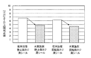
- FIG. 12 is a graph showing simulation results of Experimental Example 1 and Comparative Example 1.
- the vertical axis represents the leakage flow rate ( ⁇ 10 ⁇ 4 m 3 / s).
- the leak amount of the non-contact annular seal 117 (the stationary thread groove seal of this embodiment) shown in FIG. 6 is about 4.7 ⁇ 10 ⁇ 4 m 3 / s, and the non-contact annular seal 115 (prior art) shown in FIG.
- the leakage amount of the stationary thread groove seal was about 6.7 ⁇ 10 ⁇ 4 m 3 / s. Therefore, the leakage amount of the stationary side thread groove seal of this example is about 70% of the leakage amount of the stationary side thread groove seal of the prior art.
- the leakage amount of the non-contact annular seal 116 (the rotation side thread groove seal of this embodiment) shown in FIG. 3 is about 4.5 ⁇ 10 ⁇ 4 m 3 / s
- the non-contact annular seal 114 ( The leakage amount of the prior art rotating side thread groove seal) was about 6.2 ⁇ 10 ⁇ 4 m 3 / s. Therefore, the leakage amount of the rotation side thread groove seal of this embodiment was about 72% of the leakage amount of the conventional rotation side thread groove seal.
- the leakage amount of the non-contact annular seal of the present embodiment having the thread groove 145 in both the rotating body 126 and the fixed body 136 is the same for both the rotating body 124 and the fixed body 134. It is estimated that it is about 70% with respect to the leakage amount of the conventional non-contact annular seal having the thread groove 144 on the surface.
- Example 2 A liquid leakage flow simulation was performed on the plurality of non-contact annular seals 117 in which the threaded grooves 146 having different numbers of threads were formed on the fixed body 136 shown in FIG.
- the working fluid adopted as the simulation condition is water.
- the pressure difference between the high pressure side 155 and the low pressure side 156 was 0.6 MPa, and the rotational speed of the rotating body 126 was 3000 rpm.
- the number of thread grooves 146 included in each of the plurality of non-contact annular seals 117 is 1, 2, 4, 8, and 12.
- the cross-sectional area of the screw groove 146 at the beginning of the high-pressure side screw groove is A, the cross-sectional area is continuously reduced toward the low-pressure side, and the cross-sectional area B of the final screw groove 146 on the low-pressure side is zero. It is.
- Comparative Example 2 As Comparative Example 2, a liquid leakage flow simulation was performed on a plurality of non-contact annular seals 115 in which screw grooves 144 having different numbers of threads were formed on the fixed body 134 shown in FIG.
- the working fluid adopted as the simulation condition is water.
- the pressure difference between the high pressure side and the low pressure side was 0.6 MPa, and the rotational speed of each rotating body was 3000 rpm.
- the number of thread grooves 144 that each of the plurality of non-contact annular seals 117 has is 1, 2, 4, 8, and 12. Further, the screw groove 144 has a uniform cross-sectional area A.
- FIG. 13 is a graph showing simulation results of Experimental Example 2 and Comparative Example 2.
- the vertical axis represents the leakage amount (m3 / s).
- the amount of leakage reduction due to the thread groove pumping effect shown as “thread groove pumping effect” in the figure
- the amount of fluid leakage passing through the thread groove as a flow path due to the differential pressure in the figure, “ The amount of leakage in the thread groove ”and the total leakage amount of the entire non-contacting annular seal (shown as“ seal leakage amount ”in the figure) are shown for each number of threads.
- leakage reduction amount indicates the amount of liquid movement opposite to the amount of leakage in the thread groove due to differential pressure (hereinafter referred to as leakage amount in the thread groove). It is represented by The total leakage amount of the entire non-contact annular seal (hereinafter referred to as “seal leakage amount”) includes the leakage amount in portions other than the screw groove in addition to the sum of the leakage reduction amount and the leakage amount in the screw groove.
- the amount of seal leakage in Experimental Example 2 tends to be smaller when the number of thread grooves is larger.
- the seal leakage amount of Comparative Example 2 tends to be larger as the number of screws is larger. That is, when the number of thread grooves is 1 and 2, the difference between the seal leakage amount of Experimental Example 2 and the seal leakage amount of Comparative Example 2 is slight, but the number of thread grooves is 4 or more. In this case, the seal leakage amount of Experimental Example 2 is much smaller than the seal leakage amount of Comparative Example 2.
- the present invention can be used for a non-contact annular seal of a rotary machine such as a pump.
- Rotating body 126 ... Rotating body 127 ... Rotating body 134 ... Fixed body 136 ... Fixed body 137 ... Fixed body 144 ... Groove 145 ... Groove 146 ... Groove 147 ... Groove 151 ... Rotating shaft 155 ... High pressure side 156 ... Low pressure side 157 ... Mountain 157a ... Land part 158 ... Cross section X ... opposing part Y ... opposing part A ... arrows G ... gap W ... groove width a0 ... width a1 ... width R0 ... radius R1 ... radius
Landscapes
- Engineering & Computer Science (AREA)
- General Engineering & Computer Science (AREA)
- Mechanical Engineering (AREA)
- Structures Of Non-Positive Displacement Pumps (AREA)
- Sealing Using Fluids, Sealing Without Contact, And Removal Of Oil (AREA)
Abstract
L'invention concerne un joint d'étanchéité annulaire sans contact et une machine rotative le comportant, ceux-ci réduisant la quantité de fuite qui se produit quand un angle d'inclinaison est augmenté dans le but d'augmenter un effet de pompage. Le joint d'étanchéité annulaire sans contact est destiné à former un joint étanche pour un fluide qui s'écoule d'un côté haute pression à un côté basse pression à travers un espace entre un corps rotatif et un corps fixe, le joint d'étanchéité ayant une rainure de vis ménagée sur une surface du corps rotatif ou à une surface du corps fixe qui forment l'espace. La rainure de vis possède une région dans laquelle la surface de section transversale de la rainure de vis sur le côté basse pression est plus petite que la surface de section transversale de la rainure de vis sur le côté haute pression. La rainure de vis possède au moins quatre filets. La machine rotative possède le joint d'étanchéité annulaire sans contact.
Priority Applications (2)
| Application Number | Priority Date | Filing Date | Title |
|---|---|---|---|
| CN201680040339.1A CN107850220A (zh) | 2015-07-10 | 2016-05-02 | 非接触环状密封件及具备该密封件的旋转机械 |
| JP2017528304A JPWO2017010146A1 (ja) | 2015-07-10 | 2016-05-02 | 非接触環状シール及びこれを備える回転機械 |
Applications Claiming Priority (2)
| Application Number | Priority Date | Filing Date | Title |
|---|---|---|---|
| JP2015-138799 | 2015-07-10 | ||
| JP2015138799 | 2015-07-10 |
Publications (1)
| Publication Number | Publication Date |
|---|---|
| WO2017010146A1 true WO2017010146A1 (fr) | 2017-01-19 |
Family
ID=57758011
Family Applications (1)
| Application Number | Title | Priority Date | Filing Date |
|---|---|---|---|
| PCT/JP2016/063529 Ceased WO2017010146A1 (fr) | 2015-07-10 | 2016-05-02 | Joint d'étanchéité annulaire sans contact et machine rotative le comportant |
Country Status (3)
| Country | Link |
|---|---|
| JP (1) | JPWO2017010146A1 (fr) |
| CN (1) | CN107850220A (fr) |
| WO (1) | WO2017010146A1 (fr) |
Cited By (2)
| Publication number | Priority date | Publication date | Assignee | Title |
|---|---|---|---|---|
| JP2018185005A (ja) * | 2017-04-26 | 2018-11-22 | 株式会社荏原製作所 | ライナーリングおよび遠心ポンプ |
| CN115917171A (zh) * | 2020-07-06 | 2023-04-04 | 伊格尔工业股份有限公司 | 滑动部件 |
Families Citing this family (2)
| Publication number | Priority date | Publication date | Assignee | Title |
|---|---|---|---|---|
| DE102018205960A1 (de) * | 2018-04-19 | 2019-10-24 | Eagleburgmann Germany Gmbh & Co. Kg | Schwimmringdichtung |
| CN114893434A (zh) * | 2022-05-12 | 2022-08-12 | 鞍钢集团北京研究院有限公司 | 一种低压旋转流体泵用非接触式密封方法 |
Citations (5)
| Publication number | Priority date | Publication date | Assignee | Title |
|---|---|---|---|---|
| JPS517362A (ja) * | 1974-07-04 | 1976-01-21 | Masao Moryama | Roeiboshisochi |
| JPS55155961A (en) * | 1979-05-22 | 1980-12-04 | Mitsubishi Electric Corp | Shaft sealing device |
| JPS62101093U (fr) * | 1985-12-18 | 1987-06-27 | ||
| JP2003301793A (ja) * | 2002-04-08 | 2003-10-24 | Mitsubishi Heavy Ind Ltd | 圧縮機 |
| JP2014185627A (ja) * | 2013-03-25 | 2014-10-02 | Sekisui Plastics Tenri Co Ltd | 樹脂送出用ポンプ |
Family Cites Families (3)
| Publication number | Priority date | Publication date | Assignee | Title |
|---|---|---|---|---|
| CN101799075A (zh) * | 2010-04-12 | 2010-08-11 | 北京交通大学 | 一种旋转轴组合密封装置 |
| JP2012087892A (ja) * | 2010-10-20 | 2012-05-10 | Advics Co Ltd | 流体シールとそれを用いた軸シール装置とポンプ装置 |
| CN103620277B (zh) * | 2011-08-05 | 2016-08-17 | 伊格尔工业股份有限公司 | 机械密封件 |
-
2016
- 2016-05-02 WO PCT/JP2016/063529 patent/WO2017010146A1/fr not_active Ceased
- 2016-05-02 CN CN201680040339.1A patent/CN107850220A/zh active Pending
- 2016-05-02 JP JP2017528304A patent/JPWO2017010146A1/ja not_active Ceased
Patent Citations (5)
| Publication number | Priority date | Publication date | Assignee | Title |
|---|---|---|---|---|
| JPS517362A (ja) * | 1974-07-04 | 1976-01-21 | Masao Moryama | Roeiboshisochi |
| JPS55155961A (en) * | 1979-05-22 | 1980-12-04 | Mitsubishi Electric Corp | Shaft sealing device |
| JPS62101093U (fr) * | 1985-12-18 | 1987-06-27 | ||
| JP2003301793A (ja) * | 2002-04-08 | 2003-10-24 | Mitsubishi Heavy Ind Ltd | 圧縮機 |
| JP2014185627A (ja) * | 2013-03-25 | 2014-10-02 | Sekisui Plastics Tenri Co Ltd | 樹脂送出用ポンプ |
Cited By (2)
| Publication number | Priority date | Publication date | Assignee | Title |
|---|---|---|---|---|
| JP2018185005A (ja) * | 2017-04-26 | 2018-11-22 | 株式会社荏原製作所 | ライナーリングおよび遠心ポンプ |
| CN115917171A (zh) * | 2020-07-06 | 2023-04-04 | 伊格尔工业股份有限公司 | 滑动部件 |
Also Published As
| Publication number | Publication date |
|---|---|
| CN107850220A (zh) | 2018-03-27 |
| JPWO2017010146A1 (ja) | 2018-04-19 |
Similar Documents
| Publication | Publication Date | Title |
|---|---|---|
| CN104471293B (zh) | 具有螺旋形式或螺旋‑圆筒形混合形式的高阻尼迷宫密封件 | |
| WO2014091599A1 (fr) | Machine à fluide rotative | |
| WO2017010146A1 (fr) | Joint d'étanchéité annulaire sans contact et machine rotative le comportant | |
| CN106949245A (zh) | 一种自止旋收敛型旋转密封结构 | |
| JP6785041B2 (ja) | シール構造及びタービン | |
| CN107850221B (zh) | 非接触环状密封件及具备该非接触环状密封件的旋转机械 | |
| CN104066971B (zh) | 水力机械 | |
| JP2017110634A (ja) | ターボ機械 | |
| WO2016030952A1 (fr) | Mécanisme d'étanchéité et machine rotative | |
| JP2017020412A (ja) | 流体機械および軸封装置 | |
| CN203413119U (zh) | 仿鲨鱼皮流线形型槽端面机械密封结构 | |
| CN106678081A (zh) | 一种能降低压力脉动的旋流泵 | |
| CN112963543A (zh) | 一种扩压式自泵送流体动静压型机械密封 | |
| JP5727881B2 (ja) | 輪切形多段ポンプ | |
| JP6510983B2 (ja) | 非接触環状シール及びこれを備える回転機械 | |
| KR101261102B1 (ko) | 펌프의 성능 특성 설정 방법 및 디퓨저 베인의 제조 방법 | |
| JP2014219023A (ja) | 非接触環状シール | |
| JP2017048703A (ja) | 遠心ポンプ | |
| CN106763779B (zh) | 一种具有多锯齿形螺旋槽的机械密封环 | |
| CN102588601A (zh) | 仿花草流体型槽端面机械密封结构 | |
| CN206361151U (zh) | 一种具有多锯齿形螺旋槽的机械密封环 | |
| JP6393386B2 (ja) | 非接触環状シール | |
| KR20180056118A (ko) | 손실 저감형 임펠러 및 이를 구비한 원심압축기 | |
| CN119778309B (zh) | 一种离心泵m型密封口环 | |
| JP2017025857A (ja) | 流体機械および軸封装置 |
Legal Events
| Date | Code | Title | Description |
|---|---|---|---|
| 121 | Ep: the epo has been informed by wipo that ep was designated in this application |
Ref document number: 16824127 Country of ref document: EP Kind code of ref document: A1 |
|
| ENP | Entry into the national phase |
Ref document number: 2017528304 Country of ref document: JP Kind code of ref document: A |
|
| NENP | Non-entry into the national phase |
Ref country code: DE |
|
| 122 | Ep: pct application non-entry in european phase |
Ref document number: 16824127 Country of ref document: EP Kind code of ref document: A1 |