WO2017010156A1 - Dispositif d'observation médicale et procédé d'observation médicale - Google Patents
Dispositif d'observation médicale et procédé d'observation médicale Download PDFInfo
- Publication number
- WO2017010156A1 WO2017010156A1 PCT/JP2016/064125 JP2016064125W WO2017010156A1 WO 2017010156 A1 WO2017010156 A1 WO 2017010156A1 JP 2016064125 W JP2016064125 W JP 2016064125W WO 2017010156 A1 WO2017010156 A1 WO 2017010156A1
- Authority
- WO
- WIPO (PCT)
- Prior art keywords
- exposure
- medical observation
- value
- period
- imaging unit
- Prior art date
- Legal status (The legal status is an assumption and is not a legal conclusion. Google has not performed a legal analysis and makes no representation as to the accuracy of the status listed.)
- Ceased
Links
Images

Classifications
-
- A—HUMAN NECESSITIES
- A61—MEDICAL OR VETERINARY SCIENCE; HYGIENE
- A61B—DIAGNOSIS; SURGERY; IDENTIFICATION
- A61B1/00—Instruments for performing medical examinations of the interior of cavities or tubes of the body by visual or photographical inspection, e.g. endoscopes; Illuminating arrangements therefor
- A61B1/04—Instruments for performing medical examinations of the interior of cavities or tubes of the body by visual or photographical inspection, e.g. endoscopes; Illuminating arrangements therefor combined with photographic or television appliances
- A61B1/045—Control thereof
-
- A—HUMAN NECESSITIES
- A61—MEDICAL OR VETERINARY SCIENCE; HYGIENE
- A61B—DIAGNOSIS; SURGERY; IDENTIFICATION
- A61B1/00—Instruments for performing medical examinations of the interior of cavities or tubes of the body by visual or photographical inspection, e.g. endoscopes; Illuminating arrangements therefor
- A61B1/00002—Operational features of endoscopes
- A61B1/00004—Operational features of endoscopes characterised by electronic signal processing
- A61B1/00006—Operational features of endoscopes characterised by electronic signal processing of control signals
-
- A—HUMAN NECESSITIES
- A61—MEDICAL OR VETERINARY SCIENCE; HYGIENE
- A61B—DIAGNOSIS; SURGERY; IDENTIFICATION
- A61B1/00—Instruments for performing medical examinations of the interior of cavities or tubes of the body by visual or photographical inspection, e.g. endoscopes; Illuminating arrangements therefor
- A61B1/00002—Operational features of endoscopes
- A61B1/00004—Operational features of endoscopes characterised by electronic signal processing
- A61B1/00009—Operational features of endoscopes characterised by electronic signal processing of image signals during a use of endoscope
- A61B1/000095—Operational features of endoscopes characterised by electronic signal processing of image signals during a use of endoscope for image enhancement
-
- A—HUMAN NECESSITIES
- A61—MEDICAL OR VETERINARY SCIENCE; HYGIENE
- A61B—DIAGNOSIS; SURGERY; IDENTIFICATION
- A61B1/00—Instruments for performing medical examinations of the interior of cavities or tubes of the body by visual or photographical inspection, e.g. endoscopes; Illuminating arrangements therefor
- A61B1/04—Instruments for performing medical examinations of the interior of cavities or tubes of the body by visual or photographical inspection, e.g. endoscopes; Illuminating arrangements therefor combined with photographic or television appliances
- A61B1/05—Instruments for performing medical examinations of the interior of cavities or tubes of the body by visual or photographical inspection, e.g. endoscopes; Illuminating arrangements therefor combined with photographic or television appliances characterised by the image sensor, e.g. camera, being in the distal end portion
- A61B1/051—Details of CCD assembly
-
- G—PHYSICS
- G02—OPTICS
- G02B—OPTICAL ELEMENTS, SYSTEMS OR APPARATUS
- G02B21/00—Microscopes
- G02B21/36—Microscopes arranged for photographic purposes or projection purposes or digital imaging or video purposes including associated control and data processing arrangements
- G02B21/365—Control or image processing arrangements for digital or video microscopes
-
- G—PHYSICS
- G02—OPTICS
- G02B—OPTICAL ELEMENTS, SYSTEMS OR APPARATUS
- G02B23/00—Telescopes, e.g. binoculars; Periscopes; Instruments for viewing the inside of hollow bodies; Viewfinders; Optical aiming or sighting devices
- G02B23/24—Instruments or systems for viewing the inside of hollow bodies, e.g. fibrescopes
- G02B23/2476—Non-optical details, e.g. housings, mountings, supports
- G02B23/2484—Arrangements in relation to a camera or imaging device
-
- H—ELECTRICITY
- H04—ELECTRIC COMMUNICATION TECHNIQUE
- H04N—PICTORIAL COMMUNICATION, e.g. TELEVISION
- H04N23/00—Cameras or camera modules comprising electronic image sensors; Control thereof
- H04N23/56—Cameras or camera modules comprising electronic image sensors; Control thereof provided with illuminating means
-
- H—ELECTRICITY
- H04—ELECTRIC COMMUNICATION TECHNIQUE
- H04N—PICTORIAL COMMUNICATION, e.g. TELEVISION
- H04N23/00—Cameras or camera modules comprising electronic image sensors; Control thereof
- H04N23/70—Circuitry for compensating brightness variation in the scene
- H04N23/71—Circuitry for evaluating the brightness variation
-
- H—ELECTRICITY
- H04—ELECTRIC COMMUNICATION TECHNIQUE
- H04N—PICTORIAL COMMUNICATION, e.g. TELEVISION
- H04N23/00—Cameras or camera modules comprising electronic image sensors; Control thereof
- H04N23/70—Circuitry for compensating brightness variation in the scene
- H04N23/72—Combination of two or more compensation controls
-
- H—ELECTRICITY
- H04—ELECTRIC COMMUNICATION TECHNIQUE
- H04N—PICTORIAL COMMUNICATION, e.g. TELEVISION
- H04N23/00—Cameras or camera modules comprising electronic image sensors; Control thereof
- H04N23/70—Circuitry for compensating brightness variation in the scene
- H04N23/76—Circuitry for compensating brightness variation in the scene by influencing the image signals
-
- H—ELECTRICITY
- H04—ELECTRIC COMMUNICATION TECHNIQUE
- H04N—PICTORIAL COMMUNICATION, e.g. TELEVISION
- H04N23/00—Cameras or camera modules comprising electronic image sensors; Control thereof
- H04N23/50—Constructional details
- H04N23/555—Constructional details for picking-up images in sites, inaccessible due to their dimensions or hazardous conditions, e.g. endoscopes or borescopes
Definitions
- the present disclosure relates to a medical observation apparatus and a medical observation method.
- Patent Document 1 discloses an example of a technique in which an observation image of an endoscope is picked up by an image pickup unit and displayed as an electronic image on a display unit.
- the exposure (exposure amount) of the imaging unit is controlled so that the image of the subject to be captured becomes darker, such as by controlling the shutter speed at a higher speed or by reducing the gain.
- the present disclosure proposes a medical observation apparatus and a medical method observation method capable of suppressing a rapid change in brightness of a captured image due to disturbance.
- the acquisition unit that acquires the brightness detection result of the image of the subject in the living body, and the imaging unit according to the first period in which the brightness detection result indicates a value within a predetermined range.
- a control unit that determines a second period for maintaining the exposure at an exposure corresponding to a value included in the range.
- the processor acquires the brightness detection result of the image of the subject in the living organism, and the first detection period in which the brightness detection result indicates a value within a predetermined range. And determining a second period for maintaining the exposure of the imaging unit at an exposure corresponding to a value included in the range.
- a medical observation apparatus and a medical method observation method capable of suppressing a rapid change in brightness of a captured image due to disturbance.
- FIG. 1 is an explanatory diagram for explaining an example of a schematic configuration of a system to which the medical observation apparatus according to the present embodiment is applied.
- FIG. 1 shows an example of an endoscopic surgery system used in abdominal endoscopic surgery performed in place of a conventional laparotomy in a medical field.
- FIG. 1 shows an example of an endoscopic surgery system used in abdominal endoscopic surgery performed in place of a conventional laparotomy in a medical field.
- several opening devices called trocars 25a and 25b are attached to the abdominal wall.
- a laparoscope (hereinafter also referred to as an endoscope) 11, an energy treatment tool 22, a forceps 23, and the like are inserted into the body through holes provided in 25a and 25b.
- a treatment such as excision of the affected part U with the energy treatment tool 22 or the like is performed while viewing an image of the affected part (tumor or the like) U imaged by the endoscope 11 in real time.
- the endoscope 11, the energy treatment tool 22, and the forceps 23 are held by an operator, an assistant, a scopist, a robot, or the like.
- a cart 31 equipped with devices for endoscopic operation, a patient bed 33 on which a patient lies, a foot switch 35, and the like are arranged.
- the cart 31 includes medical devices such as a camera control unit (CCU) 13, a light source device 17, a treatment instrument device 21, a pneumoperitoneum device 24, a display device 15, a recorder 26, and a printer 27. Placed.
- CCU camera control unit
- the image signal of the affected part U imaged through the observation optical system of the endoscope 11 is transmitted to the CCU 13 via the camera cable.
- the CCU 13 may be connected to the endoscope 11 via a wireless communication path in addition to being connected to the endoscope 11 via a camera cable.
- the CCU 13 performs signal processing on the image signal output from the endoscope 11 and outputs the image signal after the signal processing to the display device 15. With such a configuration, an endoscopic image of the affected area U is displayed on the display device 15.
- the CCU 13 may cause the recorder 26 to record an endoscopic image of the affected area U as image data (for example, moving image data) by outputting the image signal after the signal processing to the recorder 26. Further, the CCU 13 may cause the printer 27 to print an endoscopic image of the affected area U by outputting the image signal after the signal processing to the printer 27.
- image data for example, moving image data
- the light source device 17 is connected to the endoscope 11 via a light guide cable, and can switch and irradiate the affected part U with light of various wavelengths.
- the light irradiated from the light source device 17 may be used as auxiliary light, for example.
- the treatment instrument device 21 corresponds to, for example, a high-frequency output device that outputs a high-frequency current to the energy treatment instrument 22 that cuts the affected part U using electric heat.
- the pneumoperitoneum device 24 includes an air supply / intake unit, and supplies air to, for example, the abdominal region in the patient.
- the foot switch 35 controls the CCU 13, the treatment instrument device 21 and the like by using a foot operation of an operator or an assistant as a trigger signal.
- the imaging unit is configured to control exposure according to the brightness of the subject image or the brightness detection result of the captured subject image (in other words, the image of the subject image to be captured).
- the brightness may be controlled).
- the subject that controls the exposure of the imaging unit is the CCU.
- the CCU is based on an image signal picked up by an image pickup device (for example, an image pickup device provided in the image pickup unit) such as a CMOS (Complementary Metal-Oxide Semiconductor) image sensor or a CCD (Charge Coupled Device) image sensor.
- an image pickup device for example, an image pickup device provided in the image pickup unit
- CMOS Complementary Metal-Oxide Semiconductor
- CCD Charge Coupled Device
- the brightness (image plane illuminance) of the subject imaged in the image is detected (detected).
- the CCU may acquire the detection result of the brightness (luminance) of the subject image from a detection unit such as a photometric sensor provided in the imaging unit.
- the detection result of the brightness of the subject image or the brightness of the captured subject image may be simply referred to as “detection value”.
- the CCU is based on the acquired detection value so that the brightness of the image of the subject imaged by the imaging unit (that is, the image plane illuminance) is in a more suitable mode (for example, appropriate exposure). ), Controlling the shutter speed of the imaging unit and the gain applied to the captured image signal (that is, controlling the exposure of the imaging unit).
- gain when “gain” is described, it indicates a gain applied to a captured image signal unless otherwise specified.
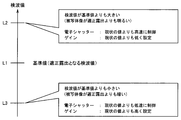
- FIG. 2 is an explanatory diagram for explaining an example of exposure control.
- reference symbol L1 indicates a detection value when the brightness of the image of the subject to be captured is appropriate (that is, a detection value when the exposure is appropriate).
- the detection value indicated by the reference symbol L1 may be referred to as a “reference value”.
- the reference symbol L2 indicates a detection value larger than the reference value L1. That is, when the detection value L2 is acquired, the brightness of the image of the subject becomes brighter than in the case of proper exposure. Therefore, in this case, the CCU controls the exposure of the imaging unit so that the exposure amount becomes smaller. Specifically, for example, the CCU controls the shutter speed of the electronic shutter of the imaging unit so as to be higher than the current value. Further, the CCU may control the gain to be lower than the current value. By such control, control is performed so that the image of the subject to be captured becomes darker, that is, the brightness of the image is closer to the brightness of the image corresponding to the reference value L1.
- the reference symbol L3 indicates a detection value that is smaller than the reference value L1. That is, when the detection value L3 is acquired, the brightness of the image of the subject is darker than in the case of proper exposure. Therefore, in this case, the CCU controls the exposure of the imaging unit so that the exposure amount is increased. Specifically, the CCU controls, for example, the shutter speed of the electronic shutter of the imaging unit to be lower than the current value. Further, the CCU may control the gain to be higher than the current value. By such control, control is performed so that the image of the subject to be captured becomes brighter, that is, the brightness of the image is closer to the brightness of the image corresponding to the reference value L1.
- the observation range of the medical observation device (that is, the imaging unit) is used in a situation where the medical observation device is used, such as endoscopic surgery of the abdomen. It can be assumed that an object different from the observation target (subject), such as forceps or gauze, is inserted into the angle of view.
- the CCU considers that the brightness within the angle of view has become brighter.
- the exposure of the imaging unit is controlled so that the image of the subject to be captured becomes darker (for example, the shutter speed is controlled to be higher or the gain is reduced).
- a phenomenon in which the brightness of the image of the subject changes abruptly such that the output image to be observed (for example, the image of the affected part in the living body) temporarily becomes dark. May become apparent.
- a change in the brightness of an image (particularly, an image to be observed such as an affected part) caused by such disturbance may impair the work of the operator who performs the treatment while observing the image.
- the medical observation apparatus has a brightness of an image to be captured even under a situation where a disturbance such as a high-luminance subject such as forceps or gauze entering the observation range may occur.
- a disturbance such as a high-luminance subject such as forceps or gauze entering the observation range may occur.
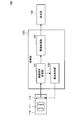
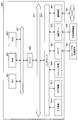
- FIG. 3 is a block diagram illustrating an example of a functional configuration of the medical observation apparatus according to the present embodiment. In particular, a function that focuses on a process of capturing an image of an observation target (subject) and displaying the image. An example of the configuration is shown.
- the medical observation apparatus 100 includes an imaging unit 110 (for example, a camera head), a control unit 130, and a display unit 150.
- the medical observation apparatus 100 illustrated in FIG. 3 can be configured as the endoscope system 1 illustrated in FIG. 1, for example. That is, the imaging unit 110, the control unit 130, and the display unit 150 illustrated in FIG. 3 correspond to, for example, the endoscope 11, the CCU 13, and the display device 15 in the endoscopic surgery system 1 illustrated in FIG. is doing.
- the imaging unit 110 corresponds to a configuration for capturing an image such as a moving image or a still image such as a so-called camera, and includes, for example, an imaging optical system (for example, a series of lens groups) 111 and an imaging element 113.
- the imaging optical system 111 forms an optical image of the subject on the imaging surface of the image sensor 113.
- the image sensor 113 for example, a CMOS image sensor, a CCD image sensor, or the like can be applied.
- the image sensor 113 converts an optical image formed on the imaging surface into an electrical signal by photoelectric conversion.
- the operation (for example, shutter speed and gain) of the image sensor 113 is controlled by the control unit 130 described later (that is, exposure is controlled by the control unit 130). Then, the image sensor 113 outputs an electrical signal generated by photoelectric conversion to the control unit 130.
- the control unit 130 includes an imaging signal processing unit 131, an image processing unit 133, and an exposure control unit 135.
- the imaging signal processing unit 131 generates an image signal by executing various processes such as a linear matrix process, a white balance process, and a ⁇ correction process on the electrical signal generated by photoelectric conversion in the image sensor 113. .
- the image signal generated by the imaging signal processing unit 131 is input to the image processing unit 133.
- the image processing unit 133 performs image processing according to the purpose such as various correction processing such as color tone correction and luminance correction, generation of a video signal, or encoding processing on the acquired image signal, and the result of the image processing is performed.
- An image based on the image is output to the display unit 150, for example.
- the imaging signal processing unit 131 outputs information necessary for exposure control of the imaging element 113 to the exposure control unit 135. More specifically, the imaging signal processing unit 131 performs detection processing on the electrical signal generated by photoelectric conversion in the imaging element 113, and the result of the detection processing (that is, the detection value) is displayed as the exposure control unit 135. Output to.
- the exposure control unit 135 acquires a detection value as a result of the detection process from the imaging signal processing unit 131, and controls the shutter speed and gain of the image sensor 113 based on the acquired detection value (that is, the exposure of the imaging unit 110 is controlled). Control). For example, as described above with reference to FIG. 2, when the detection value acquired with respect to the reference value is deviated, the exposure control unit 135 detects the detection value acquired using the reference value as a target value. The exposure of the imaging unit 110 may be controlled so as to be closer to the target value.
- the exposure control unit 135 when the exposure control unit 135 recognizes that the brightness of the image of the subject is brighter than the appropriate exposure corresponding to the reference value based on the detection value, the exposure amount is reduced. In addition, the exposure of the imaging unit 110 is controlled. In this case, for example, the exposure control unit 135 controls the shutter speed of the electronic shutter in the image sensor 113 to be higher or controls the gain to be lower.
- the exposure control unit 135 when the exposure control unit 135 recognizes that the brightness of the subject image is darker than the appropriate exposure corresponding to the reference value based on the detection value, the exposure amount is increased. In addition, the exposure of the imaging unit 110 is controlled. In this case, for example, the exposure control unit 135 controls the shutter speed of the electronic shutter in the image sensor 113 to be lower or controls the gain to be higher.
- the exposure control unit 135 performs exposure control that has been subjected to disturbance such as a high-luminance subject entering the observation range. In order to suppress the occurrence of a situation where the brightness changes suddenly, a rapid change in exposure is suppressed.
- the exposure control unit 135 when the exposure control unit 135 recognizes that the detection value indicates a value within a predetermined range, the exposure control unit 135 measures a first period in which the detection value indicates a value within the range, and Based on the measurement result of the first period, a second period for suppressing a rapid change in exposure due to disturbance is determined.
- the predetermined range that is, the range of the detection value
- the predetermined range is, for example, an allowable exposure (in other words, the brightness of the image of the subject more suitable for the observation of the target) based on the detection value corresponding to the appropriate exposure. Based on the range of
- the exposure control unit 135 also sets the exposure corresponding to the detection value within a predetermined range (for example, corresponding to the reference value) even when the detection value changes suddenly due to disturbance or the like.
- the operation of the image sensor 113 is controlled so as to be maintained at an appropriate exposure. Details of this operation will be described later together with an example of a series of processing flows of the medical observation apparatus.
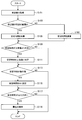
- FIG. 4 is a flowchart illustrating an example of a flow of a series of processes of the medical observation apparatus according to the present embodiment.
- Step S101 First, the imaging signal processing unit 131 performs detection processing on the electrical signal generated by photoelectric conversion in the imaging element 113, and outputs the detection processing result (ie, detection value) to the exposure control unit 135.
- Step S105 When the detection value acquired from the imaging signal processing unit 131 indicates a value within a predetermined range, the exposure control unit 135 maintains the exposure even when the detection value changes abruptly due to disturbance or the like (hereinafter referred to as the exposure value). , Referred to as “stable time Ts”).
- the stable time Ts is described as being managed based on a counter value in which one frame is one count. That is, in this case, the exposure control unit 135 increments the counter value of the stabilization time Ts.
- Step S107 the exposure control part 135 decrements the counter value of the stable time Ts, when the acquired detection value shows a value outside a predetermined range. That is, in this case, the stabilization time Ts is subtracted.
- Steps S109 and S111 An upper limit value may be provided for the stabilization time Ts.
- the exposure control unit 135 may set the counter value of the stable time Ts to the upper limit value ( S111).
- S109, NO the upper limit value
- the process indicated by the reference symbol S111 is not executed and the process proceeds to the next process.
- Steps S113 and S115 Further, the exposure control unit 135 sets the counter value of the stable time Ts to 0 when the counter value of the stable time Ts shows a negative value (S113, YES). By such control, a situation where the subtraction is performed so that the stable time Ts becomes smaller than 0 is suppressed.
- the counter value of the stable time Ts is 0 or more (S113, NO)
- the process indicated by reference numeral S115 is not executed and the process proceeds to the next process.
- Steps S117 and S119 When the counter value of the stabilization time Ts is larger than 0 (S117, YES), the exposure control unit 135 uses the detection value within the predetermined range (that is, the detection value range) as a target value. The operation of the imaging unit 110 is controlled so that the exposure of the imaging unit 110 is maintained at the exposure corresponding to the target value. As a more specific example, at this time, the exposure control unit 135 fixes the shutter speed and gain of the electronic shutter in the image sensor 113 so that the exposure of the imaging unit 110 is maintained at an appropriate exposure corresponding to the reference value. (S119).
- the exposure control unit 135 When the counter value of the stabilization time Ts is not larger than 0 (that is, when it is 0) (S117, NO), the exposure control unit 135 performs control related to maintaining the exposure indicated by reference numeral S119. do not do. In this case, for example, the exposure control unit 135 controls the exposure of the imaging unit 110 so that the detected value approaches the target value (reference value) according to the acquired detected value.
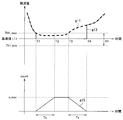
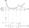
- FIG. 5 is an explanatory diagram for explaining an example of exposure control by the medical observation apparatus according to the present embodiment, and a relationship between a detection value, exposure control, and a counter value for managing a stable time.
- the horizontal axis indicates time.
- the vertical axis indicates the detection value.
- the vertical axis indicates the counter value of the stable time.
- the graph indicated by reference numeral g ⁇ b> 11 indicates a change along the time series of the detection values acquired by the imaging signal processing unit 131 based on the detection processing.
- the graph indicated by reference numeral g13 schematically shows the change in exposure along the time series based on the control by the exposure control unit 135 as the change along the time series of detection values corresponding to the exposure. Yes.
- the graph indicated by the reference sign g15 indicates a change along the time series of the counter value of the stable time.
- the reference symbol R1 indicates the above-described predetermined range (that is, the detection value range).
- a range of ⁇ TH1 around the reference value L11 is set as the predetermined range R1.
- the reference symbol TH1_max indicates the + side threshold value (that is, the upper limit value) of the predetermined range R1
- the reference symbol TH1_min is the ⁇ side threshold value (that is, the lower limit value) of the predetermined range R1.
- the detection value indicates a value within the predetermined range R1. It is possible to recognize.
- the method for setting the predetermined range R1 (that is, the detection value range) described above is merely an example, and it is not always necessary to set the reference value as the center.
- the acquired detection value indicates a value within a predetermined range R1 in the period from the timing T1 to T3, and after the timing T3, the detected value is outside the range R1.
- the value of is shown.
- the counter value of the stable time increases in time series during the period from timing T1 to T2, and thus increases along the time series, and reaches the upper limit c_max of the counter value at timing T2. .
- the detected value indicates a value within the range R1, but since the counter value of the stable time reaches the upper limit c_max, it is maintained so as not to exceed the upper limit c_max.
- the increment value of the stable time during the period from the timing T1 to the time T2 decreases along the time series, and becomes 0 at the timing T4. It becomes. That is, in the example shown in FIG. 5, the counter value increased over the time Ts from the timing T1 to T2 decreases over the time Ts and reaches zero.
- the exposure control unit 135 uses the reference value L11 (that is, the detection value within the range R1) as a target value to perform imaging.
- the operation of the imaging unit 110 is controlled so that the exposure of the unit 110 is maintained at the exposure corresponding to the target value (that is, the appropriate exposure corresponding to the reference value L11).
- the exposure control unit 135 controls the operation of the imaging unit 110 so that the exposure of the imaging unit 110 is maintained at an appropriate exposure corresponding to the reference value L11 during this period.
- the exposure control unit 135 maintains the exposure of the imaging unit 110 at an appropriate exposure corresponding to the reference value L11 during the period until the timing T4 when the counter value of the stable time decreases and reaches 0. Then, after timing T4, the exposure control is switched to follow the detection value.
- the medical observation apparatus 100 can expose the imaging unit 110 even when the detection value changes suddenly due to a disturbance such as a high-luminance subject such as forceps or gauze entering the observation range. And a sudden change in the brightness of the subject image (observation target image) is suppressed.
- the medical observation apparatus 100 according to the present embodiment even when a disturbance such as a high-luminance object such as forceps or gauze temporarily enters the observation range, the imaged observation is performed. It is possible to suppress the occurrence of a situation where the target image becomes dark.
- the acquired detection value is predetermined during the period (second period) in which the medical observation apparatus 100 maintains the exposure of the imaging unit 110 at an appropriate exposure. Is determined according to a period (first period) indicating a value within the range R1. More specifically, the medical observation apparatus 100 may indicate that the detection value indicates a value outside the range R1 as the period (first period) in which the detection value indicates a value within the predetermined range R1 is longer. Then, the period (second period) for maintaining the exposure of the imaging unit 110 at the appropriate exposure is controlled to be longer.
- the period from timing T1 to T3 corresponds to the period (first period) in which the detected value indicates a value within the predetermined range R1.
- a period from timing T1 to T4 corresponds to a period (second period) in which the exposure of the imaging unit 110 is maintained at an appropriate exposure. That is, the medical observation apparatus 100 according to the present embodiment dynamically controls a period during which the exposure of the imaging unit 110 is maintained at an appropriate exposure according to a change in brightness within the observation range. Therefore, according to the medical observation apparatus 100 according to the present embodiment, as described above, the rapid change in the brightness of the image of the subject and the brightness of the image with respect to the change in the brightness within the observation range are determined. It is possible to achieve both the following capability in a more preferable manner.
- the medical observation apparatus is based on the first period in which the detection value indicates a value within the predetermined range R1, and the second period in which a rapid change in exposure due to disturbance is suppressed. Is calculated.
- the control mode is not particularly limited.
- the medical observation apparatus 100 determines that the exposure of the imaging unit 110 is an appropriate exposure, based on the timing T1 when the acquired detection value indicates a value within the predetermined range R1. As described above, the control of the imaging unit 110 has been started. On the other hand, if the exposure of the imaging unit 110 is maintained at the exposure based on the detection value within the predetermined range R1 in the period from the timing T1 to the timing T4, the medical observation apparatus 100 does not necessarily control the operation of the imaging unit 110. Is not limited to the timing T1 in FIG.
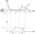
- FIG. 6 is an explanatory diagram for explaining an example of exposure control by the medical observation apparatus according to the modification of the present embodiment.
- the vertical axis and the horizontal axis of each graph shown in the upper side and the lower side in FIG. 6 correspond to the vertical axis and the horizontal axis of the graph shown in the upper side and the lower side, respectively, in FIG.
- the graphs indicated by reference numerals g11 and g15 are the same as the graphs g11 and g15 in the example shown in FIG.
- the graph indicated by the reference sign g23 corresponds to the graph g13 in FIG. 5, and the change in exposure along the time series based on the control by the medical observation apparatus 100 is represented by the time series of detection values corresponding to the exposure. This is schematically shown as a change along the line.
- the medical observation apparatus 100 starts measuring the counter value of the stable time at the timing T1.
- the medical observation apparatus 100 does not perform exposure control of the imaging unit 110 in a period in which the detection value indicates a value within the predetermined range R1, Thereafter, the exposure control of the imaging unit 110 is started with timing T3 at which the detected value is outside the range R1 as a base point, which is different from the example shown in FIG.
- the medical observation apparatus 100 In the period after the timing T3, as in the example shown in FIG. 5, the medical observation apparatus 100 exposes the imaging unit 110 during the period until the timing T4 when the counter value of the stable time decreases and reaches zero. Is maintained at an appropriate exposure corresponding to the reference value L11. After timing T4, the medical observation apparatus 100 switches the exposure control of the imaging unit 110 to control that follows the detection value. With such control, in the example illustrated in FIG. 6, the medical observation apparatus 100 captures the imaging unit 110 in a second period (a period indicated by timings T1 to T4) in which a rapid change in exposure due to disturbance is suppressed. The exposure based on the detection value within the predetermined range R1 is maintained.
- the medical observation apparatus 100 uses the reference value L11 as a target value, and the exposure of the imaging unit 110 is maintained at the exposure corresponding to the target value. As described above, the operation of the imaging unit 110 is controlled.
- the target value for controlling the exposure of the imaging unit 110 is not necessarily limited to the predetermined reference value L11.
- FIG. 7 is an explanatory diagram for explaining another example of exposure control by the medical observation apparatus according to the modification of the present embodiment.
- the vertical axis and the horizontal axis of the graph shown on each of the upper side and the lower side in FIG. 7 correspond to, for example, the vertical axis and the horizontal axis of the graph shown on the upper side and the lower side of FIG.
- the graphs indicated by reference numerals g11 and g15 are the same as the graphs g11 and g15 in the example shown in FIG.
- the graph indicated by the reference sign g33 corresponds to the graph g23 in FIG. 6, and the change in exposure along the time series based on the control by the medical observation apparatus 100 is represented by the time series of the detection values corresponding to the exposure. This is schematically shown as a change along the line.
- the operation related to the measurement of the counter value of the stable time by the medical observation apparatus 100 is the same as the example shown in FIGS.
- the medical observation device 100 sets a target value L12 different from the reference value L11 as a target value for exposure control as shown in the graph g33 in FIG.
- the example shown in FIG. 7 the medical observation device 100 sets a target value L12 different from the reference value L11 as a target value for exposure control as shown in the graph g33 in FIG.
- the medical observation apparatus 100 determines the statistics of the detection values (for example, the average of the detection values from timing T1 to T2 or a predetermined time in a period in which the acquired detection values indicate values in the range R1.
- the target value L12 is calculated based on a moving average of detection values based on the width.
- the medical observation apparatus 100 is configured so that the exposure of the imaging unit 110 is maintained at the exposure corresponding to the calculated target value L12 after the timing T3 when the acquired detection value indicates a value outside the range R1.
- the operation of the imaging unit 110 is controlled.
- the medical observation apparatus 100 performs the imaging unit 110 in the second period (a period indicated by timings T1 to T4) in which a rapid change in exposure due to disturbance is suppressed.
- the exposure based on the detection value within the predetermined range R1 is maintained.
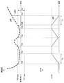
- the vertical axis and the horizontal axis of the graph shown on each of the upper side and the lower side in FIG. 8 correspond to, for example, the vertical axis and the horizontal axis of the graph shown on the upper side and the lower side of FIG.
- the graph indicated by the reference sign g ⁇ b> 41 indicates a change along the time series of the detection value acquired by the medical observation apparatus 100 (the imaging signal processing unit 131) based on the detection process.
- the graph indicated by the reference sign g43 shows the change in exposure along the time series based on the control by the medical observation apparatus 100 (exposure control unit 135) along the time series of detection values corresponding to the exposure. This is schematically shown as a change. Also, the graph indicated by reference sign g45 shows the change along the time series of the counter value of the stable time.
- the range indicated by the reference symbol R1 is the same as the example described with reference to FIGS.
- the acquired detection value indicates a value within the range R1 in the period from the timing T21 to T23, and then the disturbance in the period from the timing T23 to T24. For example, a value outside the range R1 is temporarily indicated. Further, the acquired detection value indicates a value within the range R1 during the period from the timing T24 to T26, and indicates a value outside the range R1 after the timing T26.
- the count value of the stable time increases along the time series because the detection value indicates a value within the range R1, and reaches the upper limit c_max at the timing T22. Further, in the period from timing T22 to T23, the detected value indicates a value within the range R1, but since the counter value of the stable time has reached the upper limit c_max, it is maintained so as not to exceed the upper limit c_max.
- the detection value indicates a value outside the range R1, and thus the counter value of the stable time decreases along the time series.
- the detected value indicates the value within the range R1 again before the counter value of the stable time reaches 0 at the timing T24. Therefore, during the period from timing T24 to T25, the counter value of the stable time again increases along the time series, and reaches the upper limit c_max at timing T25. Further, in the period from the timing T25 to T26, the detection value indicates a value within the range R1, but since the counter value of the stabilization time has reached the upper limit c_max, it is maintained so as not to exceed the upper limit c_max.
- the counter value of the stable time decreases in time series by time T26, and reaches 0 at the timing T27. ing.
- the medical observation apparatus 100 has the imaging unit 110 in the case where the acquired detection value indicates a value outside the range R1 and the stabilization time counter value is greater than 0.
- the operation of the imaging unit 110 is controlled so that the exposure is maintained at the exposure corresponding to the reference value L11.
- the medical observation apparatus 100 controls the operation of the imaging unit 110 so that the exposure of the imaging unit 110 is maintained at the exposure corresponding to the reference value L11.
- the medical observation apparatus 100 switches the operation of the imaging unit 110 so that the exposure value of the imaging unit 110 follows the acquired detection value.
- the acquired detection value indicates a value outside the range R1.
- the counter value of the stable time decreases along the time series from the timing T26 and reaches 0 at the timing T27. That is, the medical observation apparatus 100 controls the operation of the imaging unit 110 so that the exposure of the imaging unit 110 is maintained at the exposure corresponding to the reference value L11 during the period from timing T26 to T27. Then, after timing T27, the medical observation apparatus 100 switches the operation of the imaging unit 110 so that the exposure value of the imaging unit 110 follows the detected value.
- the period from timing T21 to T23 and the period from timing T24 to T26 in which the acquired detection value indicates a value within the range R1 correspond to the first period.
- a period from timing T21 to T27 corresponds to a second period in which a rapid change in exposure due to a disturbance is suppressed.
- the medical observation apparatus 100 has the imaging unit when the acquired detection value indicates a value outside the range R1 and the stable time counter value is greater than zero.
- the operation of the imaging unit 110 is controlled so that the exposure of 110 is maintained at the exposure corresponding to the reference value L11.
- the medical observation apparatus 100 exposes the imaging unit 110 during the determined second period in which the acquired detection value indicates a value outside the range R1.
- the exposure control by the medical observation apparatus 100 described above is merely an example, and the exposure of the imaging unit 110 is maintained at the exposure based on the detection value within the predetermined range R1 in the calculated second period.
- the mode of the control is not particularly limited.
- the medical observation apparatus 100 uses the exposure of the imaging unit 110 corresponding to the reference value L11 in the period from timing T21 to T27, as in the example described with reference to FIG.
- the operation of the imaging unit 110 may be controlled so that the exposure is maintained.
- the medical observation apparatus 100 may start exposure control of the imaging unit 110 at timing T23 and maintain the exposure control until timing T27.
- the medical observation apparatus 100 controls the operation of the imaging unit 110 so that the exposure of the imaging unit 110 is maintained at the exposure corresponding to the reference value L11 during the period from the timing T23 to T27. Good.
- the medical observation apparatus 100 separately calculates a target value L12 that is different from the reference value L11, as in the example illustrated in FIG. 7, and based on the target value L12, the imaging unit 110 Exposure may be controlled.
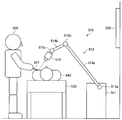
- FIG. 9 is an explanatory diagram for describing an application example of the medical observation apparatus according to the present embodiment.
- FIG. 9 schematically shows a state of treatment using a surgical video microscope apparatus.
- a doctor who is a practitioner (user) 520 uses a surgical instrument 521 such as a scalpel, a scissors, or a forceps to perform a treatment target (patient) on the treatment table 530.
- a state in which an operation is performed on 540 is illustrated.
- the treatment is a general term for various medical treatments performed on a patient who is a treatment target 540 by a doctor who is a user 520, such as surgery and examination.
- the state of the operation is illustrated as an example of the operation.
- the operation using the surgical video microscope apparatus 510 is not limited to the operation, and may be various other operations. .
- a surgical video microscope apparatus 510 is provided beside the treatment table 530.
- the surgical video microscope apparatus 510 includes a base portion 511 as a base, an arm portion 512 extending from the base portion 511, and an imaging unit 515 connected to the tip of the arm portion 512 as a tip unit.
- the arm portion 512 includes a plurality of joint portions 513a, 513b, and 513c, a plurality of links 514a and 514b connected by the joint portions 513a and 513b, and an imaging unit 515 provided at the tip of the arm portion 512.
- the arm part 512 has three joint parts 513a to 513c and two links 514a and 514b.
- the positions of the arm part 512 and the imaging unit 515 and Considering the degree of freedom of posture, the number and shape of the joint portions 513a to 513c and the links 514a and 514b, the direction of the drive shaft of the joint portions 513a to 513c, etc. may be appropriately set so as to realize a desired degree of freedom. Good.
- the joint portions 513a to 513c have a function of connecting the links 514a and 514b to each other so as to be rotatable, and the drive of the arm portion 512 is controlled by driving the rotation of the joint portions 513a to 513c.
- An imaging unit 515 is connected to the tip of the arm unit 512 as a tip unit.
- the imaging unit 515 is a unit that acquires an image to be captured, and is, for example, a camera that can capture a moving image or a still image.
- the posture of the arm unit 512 and the imaging unit 515 is operated by the surgical video microscope apparatus 510 so that the imaging unit 515 provided at the distal end of the arm unit 512 images the state of the surgical site of the surgical target 540. And the position is controlled.
- the configuration of the imaging unit 515 connected as the tip unit to the tip of the arm unit 512 is not particularly limited.
- the imaging unit 515 may be configured as an endoscope or a microscope.
- the imaging unit 515 may be configured to be detachable from the arm unit 512.
- the imaging unit 515 corresponding to the usage application may be appropriately connected to the tip of the arm unit 512 as a tip unit.
- the tip unit connected to the tip of the arm unit 512 is not necessarily limited to the imaging unit 515. .
- a display device 550 such as a monitor or a display is installed at a position facing the user 520.
- the image of the surgical site acquired by the imaging unit 515 is subjected to various types of image processing by an image processing device built in or externally attached to the surgical video microscope device 510 and then displayed on the display screen of the display device 550. Displayed as an electronic image.
- the user 520 can perform various treatments (for example, surgery) while viewing the electronic image of the treatment site displayed on the display screen of the display device 550.
- the imaging unit 515 includes, for example, the imaging unit 110 described above with reference to FIG. 3.
- an image processing apparatus that performs various types of image processing on the image of the treatment site acquired by the imaging unit 515 corresponds to an example of the control unit 130 described above with reference to FIG.
- the display device 550 corresponds to an example of the display unit 150 described above with reference to FIG.
- FIG. 10 is a functional block diagram illustrating a configuration example of the hardware configuration of the information processing apparatus 900 configured as a medical observation apparatus according to an embodiment of the present disclosure.
- the information processing apparatus 900 mainly includes a CPU 901, a ROM 903, and a RAM 905.
- the information processing apparatus 900 further includes a host bus 907, a bridge 909, an external bus 911, an interface 913, an input device 915, an output device 917, and a storage device 919. Further, the information processing apparatus 900 may include a drive 921, a connection port 923, and a communication apparatus 925.
- the CPU 901 functions as an arithmetic processing unit and a control unit, and controls all or a part of the operation in the information processing apparatus 900 according to various programs recorded in the ROM 903, the RAM 905, the storage apparatus 919, or the removable recording medium 927.
- the ROM 903 stores programs used by the CPU 901, calculation parameters, and the like.
- the RAM 905 primarily stores programs used by the CPU 901, parameters that change as appropriate during execution of the programs, and the like. These are connected to each other by a host bus 907 constituted by an internal bus such as a CPU bus.
- each structure of the control part 130 mentioned above with reference to FIG. 3 may be implement
- the host bus 907 is connected to an external bus 911 such as a PCI (Peripheral Component Interconnect / Interface) bus via a bridge 909.
- an input device 915, an output device 917, a storage device 919, a drive 921, a connection port 923, and a communication device 925 are connected to the external bus 911 via an interface 913.
- the input device 915 is an operation means operated by the user, such as a mouse, a keyboard, a touch panel, a button, a switch, a lever, and a pedal. Further, the input device 915 may be, for example, remote control means (so-called remote control) using infrared rays or other radio waves, or an external connection device such as a mobile phone or a PDA corresponding to the operation of the information processing device 900. 929 may be used. Furthermore, the input device 915 includes an input control circuit that generates an input signal based on information input by a user using the above-described operation means and outputs the input signal to the CPU 901, for example. A user of the information processing apparatus 900 can input various data and instruct a processing operation to the information processing apparatus 900 by operating the input device 915.
- the output device 917 is a device that can notify the user of the acquired information visually or audibly. Examples of such devices include CRT display devices, liquid crystal display devices, plasma display devices, EL display devices, display devices such as lamps, audio output devices such as speakers and headphones, printer devices, and the like.
- the output device 917 outputs results obtained by various processes performed by the information processing apparatus 900. Specifically, the display device displays results obtained by various processes performed by the information processing device 900 as text or images.
- the audio output device converts an audio signal composed of reproduced audio data, acoustic data, and the like into an analog signal and outputs the analog signal.
- the display unit 150 described above with reference to FIG. 3 can be realized by the output device 917, for example.
- the storage device 919 is a data storage device configured as an example of a storage unit of the information processing device 900.
- the storage device 919 includes, for example, a magnetic storage device such as an HDD (Hard Disk Drive), a semiconductor storage device, an optical storage device, or a magneto-optical storage device.
- the storage device 919 stores programs executed by the CPU 901 and various data.
- the drive 921 is a reader / writer for a recording medium, and is built in or externally attached to the information processing apparatus 900.
- the drive 921 reads information recorded on a removable recording medium 927 such as a mounted magnetic disk, optical disk, magneto-optical disk, or semiconductor memory, and outputs the information to the RAM 905.
- the drive 921 can also write a record to a removable recording medium 927 such as a magnetic disk, an optical disk, a magneto-optical disk, or a semiconductor memory that is mounted.
- the removable recording medium 927 is, for example, a DVD medium, an HD-DVD medium, a Blu-ray (registered trademark) medium, or the like.
- the removable recording medium 927 may be a compact flash (registered trademark) (CF: CompactFlash), a flash memory, an SD memory card (Secure Digital memory card), or the like. Further, the removable recording medium 927 may be, for example, an IC card (Integrated Circuit card) on which a non-contact IC chip is mounted, an electronic device, or the like.
- CF CompactFlash
- SD memory card Secure Digital memory card
- the connection port 923 is a port for directly connecting to the information processing apparatus 900.
- Examples of the connection port 923 include a USB (Universal Serial Bus) port, an IEEE 1394 port, a SCSI (Small Computer System Interface) port, and the like.
- As another example of the connection port 923 there are an RS-232C port, an optical audio terminal, an HDMI (registered trademark) (High-Definition Multimedia Interface) port, and the like.
- the communication device 925 is a communication interface configured with, for example, a communication device for connecting to a communication network (network) 931.
- the communication device 925 is, for example, a communication card for wired or wireless LAN (Local Area Network), Bluetooth (registered trademark), or WUSB (Wireless USB).
- the communication device 925 may be a router for optical communication, a router for ADSL (Asymmetric Digital Subscriber Line), a modem for various communication, or the like.
- the communication device 925 can transmit and receive signals and the like according to a predetermined protocol such as TCP / IP, for example, with the Internet or other communication devices.
- the communication network 931 connected to the communication device 925 is configured by a wired or wireless network, and may be, for example, the Internet, a home LAN, infrared communication, radio wave communication, satellite communication, or the like. .
- each component described above may be configured using a general-purpose member, or may be configured by hardware specialized for the function of each component. Therefore, it is possible to change the hardware configuration to be used as appropriate according to the technical level at the time of carrying out this embodiment.
- FIG. 10 for example, various configurations corresponding to the medical observation apparatus described above are naturally provided.
- a computer program for realizing each function of the information processing apparatus 900 constituting the medical stereoscopic observation system according to the present embodiment as described above can be produced and mounted on a personal computer or the like.
- a computer-readable recording medium storing such a computer program can be provided.
- the recording medium is, for example, a magnetic disk, an optical disk, a magneto-optical disk, a flash memory, or the like.
- the above computer program may be distributed via a network, for example, without using a recording medium.
- the medical observation apparatus when the medical observation apparatus according to the present embodiment recognizes that the detection value indicates a value within the predetermined range, the first detection value indicates the value within the range. A period is measured, and a second period for suppressing an abrupt change in exposure due to a disturbance is determined based on the measurement result of the first period. In the determined second period, the medical observation apparatus is configured such that the exposure of the imaging unit corresponds to the detection value within the range (for example, even when the detection value changes suddenly due to disturbance or the like) , The operation of the imaging unit is controlled so as to be maintained at an appropriate exposure corresponding to the reference value.
- the medical observation apparatus performs imaging even when the detection value changes suddenly due to a disturbance such as a high-luminance subject such as forceps or gauze entering the observation range.
- the exposure of the area is maintained, and a rapid change in the brightness of the image of the subject such as the affected area (the image to be observed) is suppressed. That is, according to the medical observation apparatus according to the present embodiment, even when a high-luminance object such as forceps or gauze temporarily enters the observation range, the captured image of the observation target becomes dark. It becomes possible to suppress the occurrence of the situation.
- the second period in which the medical observation apparatus according to the present embodiment suppresses an abrupt change in exposure due to a disturbance is the first period in which the detection value indicates a value within a predetermined range. To be determined. That is, the medical observation apparatus performs control so that the longer the first period, the longer the second period.
- the exposure of the imaging unit is set to an exposure corresponding to the detection value within the predetermined range (for example, appropriate exposure) according to the change in brightness within the observation range. Dynamically control the time period maintained.
- the medical observation apparatus as described above, the rapid change in the brightness of the image of the subject and the follow-up of the brightness of the image with respect to the change in the brightness within the observation range. It becomes possible to make it compatible with a more suitable aspect.
- the medical observation apparatus calculates a target value for controlling exposure of the imaging unit based on the detection result.
- the control unit calculates a target value for controlling exposure of the imaging unit based on the detection result.
- the control unit calculates a target value for controlling exposure of the imaging unit based on the detection result.
- the control unit calculates a target value for controlling exposure of the imaging unit based on the detection result.
- the control unit according to any one of (1) to (8), wherein the increment of the second period according to the first period is set within a range that does not exceed a predetermined threshold.
- Medical observation device (10) The medical observation apparatus according to any one of (1) to (9), including the imaging unit. (11)
- the imaging unit is an endoscope that is inserted into a body cavity of a patient.
- the medical observation apparatus according to (10) above.
- the imaging unit is a microscope unit including an optical system that acquires an optical image of the subject, A support part for supporting the microscope part, Further comprising The medical observation apparatus according to (10) above.
Landscapes
- Health & Medical Sciences (AREA)
- Life Sciences & Earth Sciences (AREA)
- Engineering & Computer Science (AREA)
- Surgery (AREA)
- Physics & Mathematics (AREA)
- Signal Processing (AREA)
- Multimedia (AREA)
- Optics & Photonics (AREA)
- Medical Informatics (AREA)
- Veterinary Medicine (AREA)
- Radiology & Medical Imaging (AREA)
- Nuclear Medicine, Radiotherapy & Molecular Imaging (AREA)
- Biomedical Technology (AREA)
- Heart & Thoracic Surgery (AREA)
- Biophysics (AREA)
- Molecular Biology (AREA)
- Animal Behavior & Ethology (AREA)
- General Health & Medical Sciences (AREA)
- Public Health (AREA)
- Pathology (AREA)
- General Physics & Mathematics (AREA)
- Computer Vision & Pattern Recognition (AREA)
- Chemical & Material Sciences (AREA)
- Analytical Chemistry (AREA)
- Astronomy & Astrophysics (AREA)
- Endoscopes (AREA)
- Instruments For Viewing The Inside Of Hollow Bodies (AREA)
- Microscoopes, Condenser (AREA)
- Studio Devices (AREA)
Abstract
Priority Applications (6)
| Application Number | Priority Date | Filing Date | Title |
|---|---|---|---|
| CN201680001977.2A CN106659371B (zh) | 2015-07-13 | 2016-05-12 | 医用观察设备 |
| US15/323,742 US10028647B2 (en) | 2015-07-13 | 2016-05-12 | Medical observation device and medical observation method |
| JP2016558152A JP6114889B1 (ja) | 2015-07-13 | 2016-05-12 | 医療用観察装置及び医療用観察装置の作動方法 |
| EP16816567.8A EP3158917B1 (fr) | 2015-07-13 | 2016-05-12 | Dispositif d'observation médicale et procédé d'observation médicale |
| EP19180101.8A EP3563752B1 (fr) | 2015-07-13 | 2016-05-12 | Dispositif d'observation médicale et procédé de contrôle d'exposition d'une section d'imagerie d'un dispositif d'observation médicale |
| US15/852,731 US10537233B2 (en) | 2015-07-13 | 2017-12-22 | Medical observation device and medical observation method |
Applications Claiming Priority (2)
| Application Number | Priority Date | Filing Date | Title |
|---|---|---|---|
| JP2015139312 | 2015-07-13 | ||
| JP2015-139312 | 2015-07-13 |
Related Child Applications (2)
| Application Number | Title | Priority Date | Filing Date |
|---|---|---|---|
| US15/323,742 A-371-Of-International US10028647B2 (en) | 2015-07-13 | 2016-05-12 | Medical observation device and medical observation method |
| US15/852,731 Continuation US10537233B2 (en) | 2015-07-13 | 2017-12-22 | Medical observation device and medical observation method |
Publications (1)
| Publication Number | Publication Date |
|---|---|
| WO2017010156A1 true WO2017010156A1 (fr) | 2017-01-19 |
Family
ID=57758101
Family Applications (1)
| Application Number | Title | Priority Date | Filing Date |
|---|---|---|---|
| PCT/JP2016/064125 Ceased WO2017010156A1 (fr) | 2015-07-13 | 2016-05-12 | Dispositif d'observation médicale et procédé d'observation médicale |
Country Status (5)
| Country | Link |
|---|---|
| US (2) | US10028647B2 (fr) |
| EP (2) | EP3563752B1 (fr) |
| JP (2) | JP6114889B1 (fr) |
| CN (1) | CN106659371B (fr) |
| WO (1) | WO2017010156A1 (fr) |
Families Citing this family (7)
| Publication number | Priority date | Publication date | Assignee | Title |
|---|---|---|---|---|
| JPWO2017009984A1 (ja) * | 2015-07-15 | 2018-06-07 | オリンパス株式会社 | 形状演算装置 |
| JP2018157918A (ja) * | 2017-03-22 | 2018-10-11 | ソニー株式会社 | 手術用制御装置、制御方法、手術システム、およびプログラム |
| CN110709001B (zh) * | 2017-06-12 | 2022-09-23 | 索尼公司 | 医疗系统、医疗设备和控制方法 |
| JP7286948B2 (ja) * | 2018-11-07 | 2023-06-06 | ソニーグループ株式会社 | 医療用観察システム、信号処理装置及び医療用観察方法 |
| EP4048134A4 (fr) * | 2019-10-21 | 2023-11-15 | New View Surgical, Inc. | Contrôle thermique de système d'imagerie |
| US20240335238A1 (en) * | 2021-08-26 | 2024-10-10 | Sony Group Corporation | Surgical system, control method, and program |
| JP2025033302A (ja) * | 2023-08-29 | 2025-03-13 | 富士フイルム株式会社 | 内視鏡システム及びその作動方法 |
Citations (3)
| Publication number | Priority date | Publication date | Assignee | Title |
|---|---|---|---|---|
| JP2000152913A (ja) * | 1998-09-16 | 2000-06-06 | Asahi Optical Co Ltd | 電子内視鏡 |
| JP2001037711A (ja) | 1999-07-30 | 2001-02-13 | Olympus Optical Co Ltd | 内視鏡装置 |
| JP2004321413A (ja) * | 2003-04-23 | 2004-11-18 | Olympus Corp | 電子内視鏡の光量制御装置 |
Family Cites Families (24)
| Publication number | Priority date | Publication date | Assignee | Title |
|---|---|---|---|---|
| JPH07108278B2 (ja) * | 1989-11-08 | 1995-11-22 | オリンパス光学工業株式会社 | 電子内視鏡装置 |
| JP3144711B2 (ja) * | 1992-08-14 | 2001-03-12 | オリンパス光学工業株式会社 | 湾曲部保護体 |
| JPH10165363A (ja) * | 1996-12-06 | 1998-06-23 | Olympus Optical Co Ltd | 内視鏡用撮像信号処理装置 |
| JPH10333204A (ja) | 1997-05-29 | 1998-12-18 | Sony Corp | 露出制御装置 |
| US6836288B1 (en) | 1999-02-09 | 2004-12-28 | Linvatec Corporation | Automatic exposure control system and method |
| JP4708603B2 (ja) * | 2000-06-06 | 2011-06-22 | Hoya株式会社 | ハレーションを防ぐ自動調光機能を備えた電子内視鏡装置 |
| US7199823B2 (en) * | 2001-06-18 | 2007-04-03 | Olympus Optical Co., Ltd. | Method and apparatus for improving live view performance of an image pickup apparatus for a microscope |
| JP4223778B2 (ja) * | 2001-10-01 | 2009-02-12 | Hoya株式会社 | 内視鏡用自動調光装置および電子内視鏡装置 |
| JP4139276B2 (ja) * | 2003-06-17 | 2008-08-27 | オリンパス株式会社 | 電子内視鏡装置及び信号処理装置 |
| JP2005037683A (ja) * | 2003-07-14 | 2005-02-10 | Olympus Corp | 顕微鏡用撮像装置とその制御方法、及び制御方法に係るプログラム |
| WO2005027510A1 (fr) | 2003-09-10 | 2005-03-24 | Matsushita Electric Industrial Co., Ltd. | Dispositif de traitement d'image |
| JP4047301B2 (ja) * | 2004-05-18 | 2008-02-13 | キヤノン株式会社 | 撮像装置及びその制御方法 |
| US20070024741A1 (en) * | 2004-08-30 | 2007-02-01 | Matsushita Electric Indrstrial Co., Ltd | Image processing device |
| JP2006259630A (ja) * | 2005-03-18 | 2006-09-28 | Olympus Corp | 顕微鏡用画像記録装置 |
| JP2006317406A (ja) * | 2005-05-16 | 2006-11-24 | Olympus Corp | 細胞画像撮像装置、細胞画像撮像方法、細胞画像撮像プログラム、及び細胞観察装置 |
| JP5059637B2 (ja) | 2008-01-18 | 2012-10-24 | オリンパス株式会社 | 顕微鏡用撮像装置 |
| WO2010118177A1 (fr) * | 2009-04-08 | 2010-10-14 | Zoran Corporation | Commande d'exposition pour capture d'image à gamme dynamique élevée |
| JP2012156805A (ja) * | 2011-01-26 | 2012-08-16 | Shimadzu Corp | 高速度撮影システム |
| JP5814698B2 (ja) * | 2011-08-25 | 2015-11-17 | オリンパス株式会社 | 自動露光制御装置、制御装置、内視鏡装置及び内視鏡装置の作動方法 |
| TW201331547A (zh) * | 2011-11-01 | 2013-08-01 | 尼康股份有限公司 | 形狀測定裝置、構造物製造系統、形狀測定方法、構造物製造方法、程式及記錄媒體 |
| CN102523386B (zh) * | 2011-12-16 | 2014-01-29 | 中国科学院西安光学精密机械研究所 | 基于直方图均衡化的自动曝光方法 |
| JP5654511B2 (ja) * | 2012-03-14 | 2015-01-14 | 富士フイルム株式会社 | 内視鏡システム、内視鏡システムのプロセッサ装置、及び内視鏡システムの作動方法 |
| US9413976B2 (en) * | 2012-08-08 | 2016-08-09 | Intuitive Surgical Operations, Inc. | Auto exposure of a camera in a surgical robot |
| JP6345500B2 (ja) * | 2014-06-20 | 2018-06-20 | 株式会社ソシオネクスト | デジタルカメラの露出制御方法およびデジタルカメラ |
-
2016
- 2016-05-12 CN CN201680001977.2A patent/CN106659371B/zh active Active
- 2016-05-12 EP EP19180101.8A patent/EP3563752B1/fr active Active
- 2016-05-12 WO PCT/JP2016/064125 patent/WO2017010156A1/fr not_active Ceased
- 2016-05-12 US US15/323,742 patent/US10028647B2/en active Active
- 2016-05-12 EP EP16816567.8A patent/EP3158917B1/fr active Active
- 2016-05-12 JP JP2016558152A patent/JP6114889B1/ja active Active
-
2017
- 2017-03-17 JP JP2017052339A patent/JP6784619B2/ja active Active
- 2017-12-22 US US15/852,731 patent/US10537233B2/en active Active
Patent Citations (3)
| Publication number | Priority date | Publication date | Assignee | Title |
|---|---|---|---|---|
| JP2000152913A (ja) * | 1998-09-16 | 2000-06-06 | Asahi Optical Co Ltd | 電子内視鏡 |
| JP2001037711A (ja) | 1999-07-30 | 2001-02-13 | Olympus Optical Co Ltd | 内視鏡装置 |
| JP2004321413A (ja) * | 2003-04-23 | 2004-11-18 | Olympus Corp | 電子内視鏡の光量制御装置 |
Also Published As
| Publication number | Publication date |
|---|---|
| JP2017153968A (ja) | 2017-09-07 |
| US20170196443A1 (en) | 2017-07-13 |
| JPWO2017010156A1 (ja) | 2017-07-13 |
| EP3158917A1 (fr) | 2017-04-26 |
| US10028647B2 (en) | 2018-07-24 |
| EP3158917A4 (fr) | 2017-11-29 |
| EP3563752B1 (fr) | 2023-11-01 |
| JP6114889B1 (ja) | 2017-04-12 |
| EP3563752A1 (fr) | 2019-11-06 |
| US10537233B2 (en) | 2020-01-21 |
| CN106659371B (zh) | 2018-08-28 |
| EP3158917B1 (fr) | 2019-07-03 |
| JP6784619B2 (ja) | 2020-11-11 |
| CN106659371A (zh) | 2017-05-10 |
| US20180116493A1 (en) | 2018-05-03 |
Similar Documents
| Publication | Publication Date | Title |
|---|---|---|
| JP6114889B1 (ja) | 医療用観察装置及び医療用観察装置の作動方法 | |
| US11672516B2 (en) | Control apparatus, control method, and control system | |
| CN107847107B (zh) | 医疗用观察装置与医疗用观察方法 | |
| US20190328208A1 (en) | Image processing device, image processing method and recording medium | |
| US10904437B2 (en) | Control apparatus and control method | |
| US12318065B2 (en) | Medical observation system, apparatus, control method, and imaging apparatus using different wobbling operation for different observation modes | |
| US11883120B2 (en) | Medical observation system, medical signal processing device, and medical signal processing device driving method | |
| US11523729B2 (en) | Surgical controlling device, control method, and surgical system | |
| WO2020009127A1 (fr) | Système d'observation médicale, dispositif d'observation médicale et procédé de commande de dispositif d'observation médicale | |
| JP7616064B2 (ja) | 情報処理装置、生成方法及び生成プログラム | |
| US12070183B2 (en) | Medical observation system, image processing method, and program | |
| US20200412959A1 (en) | Image processing apparatus, image processing method, and image processing program |
Legal Events
| Date | Code | Title | Description |
|---|---|---|---|
| ENP | Entry into the national phase |
Ref document number: 2016558152 Country of ref document: JP Kind code of ref document: A |
|
| WWE | Wipo information: entry into national phase |
Ref document number: 15323742 Country of ref document: US |
|
| REEP | Request for entry into the european phase |
Ref document number: 2016816567 Country of ref document: EP |
|
| WWE | Wipo information: entry into national phase |
Ref document number: 2016816567 Country of ref document: EP |
|
| 121 | Ep: the epo has been informed by wipo that ep was designated in this application |
Ref document number: 16816567 Country of ref document: EP Kind code of ref document: A1 |
|
| NENP | Non-entry into the national phase |
Ref country code: DE |