WO2017010168A1 - Outil de traitement - Google Patents
Outil de traitement Download PDFInfo
- Publication number
- WO2017010168A1 WO2017010168A1 PCT/JP2016/065050 JP2016065050W WO2017010168A1 WO 2017010168 A1 WO2017010168 A1 WO 2017010168A1 JP 2016065050 W JP2016065050 W JP 2016065050W WO 2017010168 A1 WO2017010168 A1 WO 2017010168A1
- Authority
- WO
- WIPO (PCT)
- Prior art keywords
- treatment
- contact surface
- longitudinal axis
- distal end
- treatment section
- Prior art date
- Legal status (The legal status is an assumption and is not a legal conclusion. Google has not performed a legal analysis and makes no representation as to the accuracy of the status listed.)
- Ceased
Links
Images





Classifications
-
- A—HUMAN NECESSITIES
- A61—MEDICAL OR VETERINARY SCIENCE; HYGIENE
- A61B—DIAGNOSIS; SURGERY; IDENTIFICATION
- A61B18/00—Surgical instruments, devices or methods for transferring non-mechanical forms of energy to or from the body
- A61B18/04—Surgical instruments, devices or methods for transferring non-mechanical forms of energy to or from the body by heating
- A61B18/12—Surgical instruments, devices or methods for transferring non-mechanical forms of energy to or from the body by heating by passing a current through the tissue to be heated, e.g. high-frequency current
- A61B18/14—Probes or electrodes therefor
- A61B18/1442—Probes having pivoting end effectors, e.g. forceps
-
- A—HUMAN NECESSITIES
- A61—MEDICAL OR VETERINARY SCIENCE; HYGIENE
- A61B—DIAGNOSIS; SURGERY; IDENTIFICATION
- A61B18/00—Surgical instruments, devices or methods for transferring non-mechanical forms of energy to or from the body
- A61B18/04—Surgical instruments, devices or methods for transferring non-mechanical forms of energy to or from the body by heating
- A61B18/12—Surgical instruments, devices or methods for transferring non-mechanical forms of energy to or from the body by heating by passing a current through the tissue to be heated, e.g. high-frequency current
- A61B18/14—Probes or electrodes therefor
-
- A—HUMAN NECESSITIES
- A61—MEDICAL OR VETERINARY SCIENCE; HYGIENE
- A61B—DIAGNOSIS; SURGERY; IDENTIFICATION
- A61B18/00—Surgical instruments, devices or methods for transferring non-mechanical forms of energy to or from the body
- A61B18/04—Surgical instruments, devices or methods for transferring non-mechanical forms of energy to or from the body by heating
- A61B18/12—Surgical instruments, devices or methods for transferring non-mechanical forms of energy to or from the body by heating by passing a current through the tissue to be heated, e.g. high-frequency current
- A61B18/1206—Generators therefor
-
- A—HUMAN NECESSITIES
- A61—MEDICAL OR VETERINARY SCIENCE; HYGIENE
- A61B—DIAGNOSIS; SURGERY; IDENTIFICATION
- A61B18/00—Surgical instruments, devices or methods for transferring non-mechanical forms of energy to or from the body
- A61B2018/00053—Mechanical features of the instrument of device
- A61B2018/00059—Material properties
- A61B2018/00071—Electrical conductivity
- A61B2018/00083—Electrical conductivity low, i.e. electrically insulating
-
- A—HUMAN NECESSITIES
- A61—MEDICAL OR VETERINARY SCIENCE; HYGIENE
- A61B—DIAGNOSIS; SURGERY; IDENTIFICATION
- A61B18/00—Surgical instruments, devices or methods for transferring non-mechanical forms of energy to or from the body
- A61B2018/00315—Surgical instruments, devices or methods for transferring non-mechanical forms of energy to or from the body for treatment of particular body parts
- A61B2018/00345—Vascular system
- A61B2018/00404—Blood vessels other than those in or around the heart
-
- A—HUMAN NECESSITIES
- A61—MEDICAL OR VETERINARY SCIENCE; HYGIENE
- A61B—DIAGNOSIS; SURGERY; IDENTIFICATION
- A61B18/00—Surgical instruments, devices or methods for transferring non-mechanical forms of energy to or from the body
- A61B2018/00571—Surgical instruments, devices or methods for transferring non-mechanical forms of energy to or from the body for achieving a particular surgical effect
- A61B2018/00589—Coagulation
-
- A—HUMAN NECESSITIES
- A61—MEDICAL OR VETERINARY SCIENCE; HYGIENE
- A61B—DIAGNOSIS; SURGERY; IDENTIFICATION
- A61B18/00—Surgical instruments, devices or methods for transferring non-mechanical forms of energy to or from the body
- A61B2018/00571—Surgical instruments, devices or methods for transferring non-mechanical forms of energy to or from the body for achieving a particular surgical effect
- A61B2018/00607—Coagulation and cutting with the same instrument
-
- A—HUMAN NECESSITIES
- A61—MEDICAL OR VETERINARY SCIENCE; HYGIENE
- A61B—DIAGNOSIS; SURGERY; IDENTIFICATION
- A61B18/00—Surgical instruments, devices or methods for transferring non-mechanical forms of energy to or from the body
- A61B2018/00571—Surgical instruments, devices or methods for transferring non-mechanical forms of energy to or from the body for achieving a particular surgical effect
- A61B2018/0063—Sealing
-
- A—HUMAN NECESSITIES
- A61—MEDICAL OR VETERINARY SCIENCE; HYGIENE
- A61B—DIAGNOSIS; SURGERY; IDENTIFICATION
- A61B18/00—Surgical instruments, devices or methods for transferring non-mechanical forms of energy to or from the body
- A61B18/04—Surgical instruments, devices or methods for transferring non-mechanical forms of energy to or from the body by heating
- A61B18/12—Surgical instruments, devices or methods for transferring non-mechanical forms of energy to or from the body by heating by passing a current through the tissue to be heated, e.g. high-frequency current
- A61B18/1206—Generators therefor
- A61B2018/1246—Generators therefor characterised by the output polarity
- A61B2018/1253—Generators therefor characterised by the output polarity monopolar
-
- A—HUMAN NECESSITIES
- A61—MEDICAL OR VETERINARY SCIENCE; HYGIENE
- A61B—DIAGNOSIS; SURGERY; IDENTIFICATION
- A61B18/00—Surgical instruments, devices or methods for transferring non-mechanical forms of energy to or from the body
- A61B18/04—Surgical instruments, devices or methods for transferring non-mechanical forms of energy to or from the body by heating
- A61B18/12—Surgical instruments, devices or methods for transferring non-mechanical forms of energy to or from the body by heating by passing a current through the tissue to be heated, e.g. high-frequency current
- A61B18/1206—Generators therefor
- A61B2018/1246—Generators therefor characterised by the output polarity
- A61B2018/126—Generators therefor characterised by the output polarity bipolar
-
- A—HUMAN NECESSITIES
- A61—MEDICAL OR VETERINARY SCIENCE; HYGIENE
- A61B—DIAGNOSIS; SURGERY; IDENTIFICATION
- A61B18/00—Surgical instruments, devices or methods for transferring non-mechanical forms of energy to or from the body
- A61B18/04—Surgical instruments, devices or methods for transferring non-mechanical forms of energy to or from the body by heating
- A61B18/12—Surgical instruments, devices or methods for transferring non-mechanical forms of energy to or from the body by heating by passing a current through the tissue to be heated, e.g. high-frequency current
- A61B18/14—Probes or electrodes therefor
- A61B18/1442—Probes having pivoting end effectors, e.g. forceps
- A61B2018/145—Probes having pivoting end effectors, e.g. forceps wherein the effectors remain parallel during closing and opening
-
- A—HUMAN NECESSITIES
- A61—MEDICAL OR VETERINARY SCIENCE; HYGIENE
- A61B—DIAGNOSIS; SURGERY; IDENTIFICATION
- A61B18/00—Surgical instruments, devices or methods for transferring non-mechanical forms of energy to or from the body
- A61B18/04—Surgical instruments, devices or methods for transferring non-mechanical forms of energy to or from the body by heating
- A61B18/12—Surgical instruments, devices or methods for transferring non-mechanical forms of energy to or from the body by heating by passing a current through the tissue to be heated, e.g. high-frequency current
- A61B18/14—Probes or electrodes therefor
- A61B18/1442—Probes having pivoting end effectors, e.g. forceps
- A61B2018/1452—Probes having pivoting end effectors, e.g. forceps including means for cutting
Definitions
- This invention relates to a treatment instrument.
- a living tissue can be coagulated by sandwiching the living tissue between a fixed electrode on the distal end side and a movable electrode that slides along the longitudinal axis direction toward the fixed electrode.
- a treatment tool is disclosed. For example, when a living tissue to be treated exists in a body cavity or the like, treatment is performed by inserting an endoscope and a treatment tool from different trocars.
- the treatment instrument disclosed in Japanese Patent Laid-Open No. 2001-61848 is easy to coagulate such as sealing a blood vessel, but it is appropriate to perform an appropriate treatment such as incising or peeling a living tissue. It can be difficult. In such a case, it is necessary to replace the treatment instrument other than the treatment instrument disclosed in Japanese Patent Laid-Open No. 2001-61848 with a trocar or the like.
- the present invention provides a treatment instrument that can coagulate a living tissue and can perform an appropriate treatment such as a treatment of incising or peeling the living tissue without replacement. For the purpose.
- the treatment tool includes a sheath that defines a longitudinal axis by a distal end and a proximal end, a first member having a first contact surface that contacts a living tissue, and the first contact surface facing the first member.
- a second member having a second contact surface that comes into contact with the living tissue on a proximal side with respect to the first contact surface along the longitudinal axis, and between the first contact surface and the second contact surface
- a first treatment section capable of coagulating the living tissue by applying energy to the sandwiched living tissue, and moving at least one of the first member and the second member along the longitudinal axis, and the first contact
- a moving mechanism that switches between a closed position in which the surface and the second contact surface are close to each other and an open position in which the first contact surface and the second contact surface are separated from each other, and the first treatment unit,
- the contact surface and the second contact surface are located at the closed position, Is located closer to the distal side along the longitudinal axis than the distal end of the first treatment section, and when the first contact surface and the second contact surface are located at the open position, the distal end is the first And a second treatment section at the same position as the distal end of the treatment section or a position closer to the proximal end than the dis
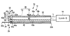
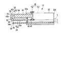
- FIG. 1A shows the treatment system according to the first embodiment, and with the first treatment portion closed, the distal end of the second treatment portion is projected toward the distal end along the longitudinal axis with respect to the first treatment portion. It is the schematic which shows a state.
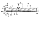
- FIG. 1B shows the treatment instrument according to the first embodiment. With the first treatment part open, the distal end of the second treatment part is based on the longitudinal axis with respect to the first contact surface of the first treatment part. It is the schematic which shows the state arrange
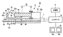
- FIG. 2A shows a treatment system according to a first modification of the first embodiment, and the distal end of the second treatment unit is advanced along the longitudinal axis with respect to the first treatment unit in a state where the first treatment unit is closed.
- FIG. 2B shows a treatment instrument according to a first modification of the first embodiment, and the distal end of the second treatment portion is elongated with respect to the first contact surface of the first treatment portion in a state where the first treatment portion is opened. It is the schematic which shows the state arrange
- FIG. 3A shows a treatment instrument according to a second modification of the first embodiment, with the distal end of the second treatment part extending along the longitudinal axis with respect to the first treatment part in a state where the first treatment part is closed. It is the schematic which shows the state protruded to the side.
- FIG. 3B is a schematic diagram illustrating a state in which the treatment tool according to the second modification example of the first embodiment is viewed from the direction of the arrow 3B in FIG. 3A.
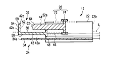
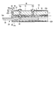
- FIG. 4A shows the treatment system according to the second embodiment, and the distal end of the second treatment portion protrudes toward the distal end along the longitudinal axis with respect to the first treatment portion with the first treatment portion appropriately opened. It is the schematic which shows the state made to do.
- FIG. 4B shows the treatment tool according to the second embodiment, and with the first treatment part opened, the distal end of the second treatment part is elongated along the longitudinal axis with respect to the first contact surface of the first treatment part. It is the schematic which shows the state arrange
- FIG. 4C shows the treatment tool according to the second embodiment, and with the first treatment part closed, the distal end of the second treatment part is elongated along the longitudinal axis with respect to the first contact surface of the first treatment part.
- FIG. 5A shows a state in which the first treatment unit in the treatment area is switched to the closed position by operating the moving mechanism of the treatment tool according to the third embodiment, and the second treatment unit is pulled into the first treatment unit.
- FIG. 5B illustrates a state in which the first treatment unit in the treatment region is switched to the open position by operating the movement mechanism of the treatment tool according to the third embodiment, and the second treatment unit is pulled into the first treatment unit.
- FIG. FIG. 5A shows a state in which the first treatment unit in the treatment area is switched to the closed position by operating the moving mechanism of the treatment tool according to the third embodiment, and the second treatment unit is pulled into the first treatment unit.
- FIG. FIG. 5B illustrates a state in which the first treatment unit in the treatment region is switched to the open position by operating the movement mechanism
- 5C is a diagram illustrating the operation of the moving mechanism of the treatment tool according to the third embodiment to switch the first treatment unit in the treatment region to the closed position, and to project the second treatment unit from the distal end of the first treatment unit. It is the schematic which shows the state.
- FIG. 1A 1st Embodiment is described using FIG. 1A and FIG. 1B.
- a treatment system (treatment tool unit) 10 includes a treatment tool 12 and a controller 14.
- a foot switch 16 is connected to the controller 14.
- a hand switch (not shown) can be disposed on the treatment instrument 12 together with the foot switch 16 or instead of the foot switch 16.
- a counter electrode P is connected to the controller 14.
- the treatment instrument 12 includes a cylindrical sheath 22, a treatment region 24 protruding from the distal end 22a of the sheath 22, and a moving mechanism 26.
- the sheath 22 defines a longitudinal axis L by its distal end 22a and proximal end 22b.
- the sheath 22 has electrical insulation.
- the treatment region 24 includes a first treatment part 32 and a second treatment part 34.
- the shape of the distal end portion of the second treatment portion 34 is formed straight, but is not particularly limited, and can be used in an appropriate shape such as a hook shape or a spatula shape. .
- the first treatment unit 32 can perform a bipolar treatment.
- the first treatment section 32 includes a first member 42 and a second member 44.
- Each of the first member 42 and the second member 44 is preferably formed of a conductive metal material.
- the 1st member 42 and the 2nd member 44 may be formed with the same raw material, and may be formed with a different raw material. Both the first member 42 and the second member 44 are electrically connected to the controller 14.
- the first member 42 includes a shaft portion 42a that extends, for example, parallel to the longitudinal axis L, and an action portion that is bent in a direction in which the tip of the shaft portion 42a intersects the longitudinal axis L. 42b.
- the action part 42b is bent, for example, in a substantially L shape.
- the angle of the action portion 42b with respect to the shaft portion 42a is shown as 90 °, but is not limited to 90 °, and may be bent to an appropriate angle.
- the portion indicated by reference numerals 54 and 58 which will be described later, that is, the boundary portion between the shaft portion 42a and the action portion 42b is formed in a curved surface, such as chamfered. is there.
- the boundary portion between the surfaces indicated by reference numerals 52 and 56 is preferably formed in a curved surface such as chamfered.
- the second member 44 extends, for example, in parallel to the longitudinal axis L, similarly to the shaft portion 42a of the first member 42, and is formed as a columnar rod, for example.
- the action part 42b of the first member 42 has a first contact surface 52 that treats the living tissue while in contact with the living tissue.
- the action part 42 b of the first member 42 protrudes with respect to the distal end 22 a of the sheath 22.
- the first contact surface 52 is directed to the distal end 22 a of the sheath 22. That is, the first contact surface 52 is directed along the longitudinal axis L toward the base end side.
- the second member 44 is located closer to the proximal end along the longitudinal axis L than the first contact surface 52, faces the first contact surface 52, and contacts the living tissue with the first contact surface 52. It has the 2nd contact surface 62 to treat.
- the second contact surface 62 is directed along the longitudinal axis L toward the tip side.
- the first contact surface 52 and the second contact surface 62 are preferably parallel to each other.
- the first contact surface 52 and the second contact surface 62 are not limited to be directed along the longitudinal axis L, and the normal lines of the first contact surface 52 and the second contact surface 62 are shifted from the longitudinal axis L. Of course, it is suitable to be formed as a slope.
- the first contact surface 52 and the second contact surface 62 are each used as a high-frequency electrode.
- the first contact surface 52 and the second contact surface 62 of the first treatment section 32 can coagulate, for example, seal the sandwiched living tissue when energy is applied with the living tissue sandwiched between them.
- Bipolar treatment can be performed. If the living tissue is a blood vessel, the sandwiched blood vessel is sealed by bipolar treatment.
- the first member 42 has an electrical insulating portion 54 that prevents the living tissue from being treated when the above-described energy is applied in contact with the living tissue.
- the electrical insulating portion 54 is formed by, for example, an insulating coating. It is preferable that the electrical insulating portion 54 has heat resistance.
- the electrical insulating portion 54 is formed on the back surface with respect to the first contact surface 52. That is, the electrical insulating portion 54 is on the distal end surface of the first member 42 and is directed along the longitudinal axis L toward the distal end side.
- a portion indicated by reference numeral 56 in the vicinity of the boundary with the action portion 42 b of the shaft portion 42 a of the first member 42 and close to the tip of the second member 44 is formed as an electrode similarly to the first contact surface 52. It may be formed as an electrical insulating part.
- An electrical insulating portion 58 is formed on the back surface (distal surface) of the portion indicated by reference numeral 56. It is preferable that the electrical insulating portions 54 and 58 are formed continuously without a break.
- the electrical insulating portion 58 is formed by, for example, an insulating coating.
- the first member 42 prevents the treatment of the living tissue when the above-described energy is applied while being in contact with the living tissue, not only by the electric insulating portion 54 but also by the electric insulating portion 58.
- the distal end 42c with respect to the long shaft portion 42a is also preferably formed as an electrical insulating portion 59.
- the distal end 42 c forms an opening entrance where the living tissue is disposed between the distal end 42 c and the second contact surface 62 of the second member 44.
- the second member 44 has an electrical insulating portion 64 that prevents the living tissue from being treated when the above-described energy is applied in contact with the living tissue.
- the electrical insulating portion 64 is formed in a portion excluding the second contact surface 62. Specifically, an insulating coating is applied to the outer peripheral surface around the longitudinal axis of the second member 44. For this reason, the sliding surface between the first member 42 and the second member 44 is electrically insulated. In addition, it is suitable for the electric insulation part 64 to have heat resistance.
- the moving mechanism 26 can move the second member 44 along the longitudinal axis L within a predetermined range.
- An appropriate mechanism can be used as the moving mechanism 26.
- the second member 44 can be moved along the longitudinal axis L within a predetermined range with respect to the sheath 22 using a linear motor.
- the moving mechanism 26 will be briefly described with respect to an example in which the user manually moves the second member 44 along the longitudinal axis L with respect to the sheath 22.
- the sheath 22 is formed with a groove 72 that is longer along the longitudinal axis L than the circumferential direction of the longitudinal axis L and that defines a moving range in which the second member 44 is moved along the longitudinal axis L.
- a slide lever (slider) 74 is disposed in the groove 72 as an operating body. The slide lever 74 can move between the distal end and the proximal end of the groove 72 along the longitudinal axis L.
- the slide lever 74 has electrical insulation.
- the slide lever 74 is connected to the second member 44. That is, as an example, the moving mechanism 26 includes a groove 72 formed in the sheath 22 and a slide lever 74 connected to the second member 44.
- the moving mechanism 26 can bring the slide lever 74 into contact with the distal end of the groove 72 when the slide lever 74 is moved along the longitudinal axis L toward the distal end side of the sheath 22.
- the moving mechanism 26 can bring the slide lever 74 into contact with the proximal end of the groove 72 when the slide lever 74 is moved along the longitudinal axis L toward the proximal end side of the sheath 22.
- the movable range of the slide lever 74 can be defined by the groove 72.
- the first contact surface 52 of the first member 42 is separated from the second contact surface 62 of the second member 44. . Therefore, the first contact surface 52 of the first member 42 and the second contact surface 62 of the second member 44 are in an open position where they are separated from each other.
- the slide lever 74 is brought into contact with the proximal end of the groove 72 of the sheath 22 along the longitudinal axis L, the first contact surface 52 of the first member 42 is close to the second contact surface 62 of the second member 44. To do. Therefore, the first contact surface 52 of the first member 42 and the second contact surface 62 of the second member 44 are close to each other.
- the first contact surface 52 and the second contact surface 62 are not in contact with each other, and a slight gap is formed.
- the distance between the first contact surface 52 and the second contact surface 62 can be adjusted, and the opening amount can be adjusted. That is, the moving mechanism 26 moves the first member 42 along the longitudinal axis L so that the first contact surface 52 and the second contact surface 62 are close to each other, and the first contact surface 52 and the second contact surface 62. Can be switched to a separated open position.
- the second treatment section 34 is formed in a rod shape thinner than the second member 44. 1A to 2, the second treatment portion 34 has a shape extending straight along the longitudinal axis L, but as described above, the shape can be set as appropriate.
- the 2nd treatment part 34 is used as a high frequency electrode as an example.
- the second treatment unit 34 is a monopolar type treatment in which when the energy is applied while being in contact with the living tissue between the counter electrode P attached to the patient, the contacted living tissue is incised or separated. It can be performed.
- the second treatment part 34 is arranged in parallel with the first treatment part 32.
- the second treatment portion 34 is located on the distal end side along the longitudinal axis L with respect to the electrical insulating portion 54 on the distal end surface of the first treatment portion 32.
- the second treatment section 34 is located on the distal end side along the longitudinal axis L from the first treatment section 32 when the first contact surface 52 and the second contact surface 62 are located at the closed position, By applying energy to the living tissue, the living tissue can be incised or peeled off.
- the second treatment section 34 When the first treatment section 32 is switched to the open position, the second treatment section 34 is located at the same position or the proximal end side along the longitudinal axis L from the distal end of the first treatment section 32. When the first treatment section 32 is switched to the open position, the second treatment section 34 is located at the same position or the proximal end side along the longitudinal axis L with respect to the first contact surface 52 of the first treatment section 32. ing.
- the 1st treatment part 32 and the 2nd treatment part 34 are not electrically connected, but are electrically insulated.
- the first treatment portion 32 and the second treatment portion 34 are electrically insulated by insulating coating or the like.
- the controller 14 can output energy to the first treatment unit 32, for example, in accordance with an instruction from the foot switch 16, and perform control to perform bipolar treatment in the first treatment unit 32. 2
- the energy can be output to the treatment unit 34 and the second treatment unit 34 can perform control to perform a monopolar treatment.
- the foot switch 16 of the treatment system 10 includes a first switch 16a and a second switch 16b.
- the first switch 16a issues an instruction to output energy from the controller 14 when the first treatment section 32 performs a bipolar treatment by a pressing operation.
- the second switch 16b issues an instruction to output energy when the second treatment unit 34 performs a monopolar treatment by a pressing operation.
- the treatment instrument 12 is used with an endoscope (not shown) via a trocar.
- the user attaches the counter electrode P to an appropriate place of the patient.
- the user holds the treatment tool 12 appropriately and makes the treatment region 24 confront the body tissue or layered tissue while confirming the observation image of the endoscope. Since the second treatment portion 34 of the treatment region 24 is formed thin, approachability can be maintained.
- the distal end 34a of the second treatment portion 34 is projected toward the distal end along the longitudinal axis L with respect to the distal end of the first treatment portion 32.
- a monopolar treatment is performed on the living tissue by the second treatment section 34 in the treatment region 24.
- Monopolar type high-frequency energy is applied to the biological tissue to be treated, and the high-frequency current is collected by the counter electrode P attached to the patient, so that the biological tissue in contact with the second treatment section 34 is incised or delaminated. I will let you.
- the pressing operation of the second switch 16b is only when it is actually desired to perform an incision or the like, and normally the pressing of the second switch 16b is released.
- the first treatment part 32 and the second treatment part 34 are electrically insulated. For this reason, when the monopolar treatment is performed using the second treatment section 34, no current flows through the first treatment section 32. When the electrical insulating portions 54, 58, 59 of the first treatment section 32 come into contact with a living tissue at an appropriate position, no current flows through the contacting living tissue. For this reason, the electrical insulation parts 54, 58, 59 of the first treatment part 32 prevent an unintentional flow of a high-frequency current through the living tissue. That is, an unintended treatment by the treatment area 24 is prevented.
- blood vessels may be exposed.
- the blood vessel is sealed, that is, coagulated.
- the user operates the slide lever 74 along the groove 72 to move the first contact surface 52 of the first member 42 and the second contact surface 62 of the second member 44 as shown in FIG. 1B. Switch to the open position.
- the distal end of the first treatment section 32 is protruded with respect to the distal end 34 a of the second treatment section 34.
- the first contact surface 52 of the first treatment section 32 is protruded with respect to the distal end 34 a of the second treatment section 34.
- the blood vessel is disposed between the first contact surface 52 of the first member 42 of the first treatment section 32 and the second contact surface 62 of the second treatment section 34.
- the user moves the slide lever 74 to switch the first contact surface 52 of the first member 42 and the second contact surface 62 of the second member 44 to the closed position.
- the blood vessel contacts both the first contact surface 52 of the first member 42 and the second contact surface 62 of the second member 44.
- the first contact surface 52 and the second contact surface 62 are not electrically connected.
- the first switch 16a is pressed, and the first treatment unit 32 performs a bipolar treatment on the biological tissue to be treated such as a blood vessel.
- both the first contact surface 52 of the first member 42 of the first treatment section 32 and the second contact surface 62 of the second member 44 are brought into contact with each other.
- Blood vessels are coagulated by Joule heat. For this reason, bleeding from the coagulated portion is prevented.
- the first treatment unit 32 is switched to the open position to release the blood vessel, and then switched to the closed position. Then, the second treatment section 34 is used to cut the coagulated portion of the blood vessel. At this time, it is only necessary to move the treatment area 24, and it is not necessary to replace the treatment tool 12 by removing it from the trocar.
- the 1st treatment part 32 when switching the 1st treatment part 32 from an open position to a closed position or from a closed position to an open position, the 1st member 42 and the 2nd member 44 only move relatively back and forth. For this reason, the structure is simple, and it is difficult to impede visibility when a blood vessel or the like is disposed between the first contact surface 52 of the first member 42 and the second contact surface 62 of the second member 44.
- a monopolar treatment such as an incision by the second treatment section 34
- a bipolar treatment by the first treatment section 32 is performed.
- a monopolar treatment by the second treatment unit 34 is performed, and a desired blood vessel is cut by the bipolar treatment, for example, to finish the desired treatment.
- the distal end 34 a of the second treatment portion 34 is located on the distal end side along the longitudinal axis L with respect to the distal end of the first treatment portion 32. .
- the second treatment section 34 can appropriately perform treatment such as incision and separation on the biological tissue to be treated.
- the distal end 34a of the second treatment section 34 is located at the same position as the distal end of the first treatment section 32 or from the distal end of the first treatment section 32.
- the distal end of the first treatment section 32 is closer to the distal end side than the distal end 34 a of the second treatment section 34. Can be arranged. For this reason, it is easy to bring the blood vessel into contact with the first contact surface 52.
- the blood vessel can be easily brought into contact with both the first contact surface 52 and the second contact surface 62 in a state where the blood vessel is hardly affected by the presence of the second treatment unit 34.
- the first treatment section 32 when the first treatment section 32 is in the closed position, even if the distal end 34a of the second treatment section 34 is closer to the distal end side along the longitudinal axis L than the distal end of the first treatment section 32, the first treatment section 32 is When switched to the open position, a part of the first treatment section 32 is located on the distal end side along the longitudinal axis L with respect to the distal end 34a of the second treatment section 34. For this reason, using the treatment instrument 12 according to this embodiment, it is possible to easily perform a treatment such as appropriately sealing a biological tissue such as a blood vessel with the first treatment section 32.
- the second treatment unit 34 After sealing the blood vessel, the second treatment unit 34 again advances treatment such as incision and peeling to the treatment target biological tissue while maintaining the state where the treatment region 24 is close to the treatment target biological tissue. be able to. Therefore, the treatment region 24 can be maintained close to the treatment target biological tissue, and the treatment can be performed with one treatment tool 12 without replacement. For this reason, treatment time can be shortened and the treatment property of the biological tissue to be treated can be greatly improved.
- the treatment tool 12 when the treatment tool 12 is used together with an endoscope, it is not necessary to replace the treatment tool 12. Therefore, it is possible to maintain a state in which the treatment region 24 is always close to the treatment target while the treatment region 24 is disposed within the observation visual field of the endoscope. For this reason, once the treatment region 24 is placed in the field of view of the endoscope, the trouble of arranging the treatment region 24 in the field of view of the endoscope can be saved. That is, the treatment can be performed in a state in which the treatment region 24 is disposed in the field of view of the endoscope only by confronting the treatment region 24 with the living tissue to be treated.
- the second treatment part 34 is formed thinner than the first treatment part 32. For this reason, the second treatment unit 34 can appropriately perform a finer treatment than the first treatment unit 32.
- the second treatment unit 34 can proceed with the treatment of the living tissue without adding energy from the controller 14 such as hooking the exposed blood vessel to separate it from the living tissue.
- the first contact surface 52 of the first member 42 is also preferably used as a first heater (not shown) instead of being used as a high frequency electrode.
- the second contact surface 62 of the second member 44 is also preferably used as a second heater (not shown) instead of being used as a high frequency electrode.
- the 1st contact surface 52 and the 2nd contact surface 62 may contact mutually.
- the 1st heater and the 2nd heater are formed in the plate shape which can be heated up to about several hundred degrees in several seconds.
- This treatment tool 12 can be used in the same manner as the treatment tool 12 described in the first embodiment.
- the first heater and the second heater it is possible to perform a treatment in which the living tissue is coagulated by the first treatment unit 32 and sealed if it is a blood vessel. Further, when the first heater and the second heater are used, the living tissue can be incised as well as solidified by setting the energy amount.
- the energy used for the treatment by the treatment instrument 12 is not limited to the high frequency energy, and heat energy can be appropriately used.
- the treatment tool 12 should just have at least one among a 1st heater and a 2nd heater.
- the first contact surface 52 of the first treatment section 32 may be formed as an electrode, and the first heater may be embedded in the first contact surface 52.
- the second contact surface 62 of the first treatment section 32 may be formed as an electrode, and the second heater may be embedded in the second contact surface 62. That is, the first contact surface 52 and the second contact surface 62 of the first treatment section 32 are used as both a high frequency electrode and a heater. In this case, the first contact surface 52 and the second contact surface 62 are not brought into contact with each other.
- the living tissue can be coagulated or incised by the heat energy from the heater while the living tissue such as a blood vessel is sealed with high-frequency energy.
- the time required to seal the blood vessel with high-frequency energy can be increased.
- the treatment capability is improved, The sealing time can be shortened.
- heat transfer by a heater can be used instead of performing monopolar type high frequency energy treatment on the second treatment section 34.
- heat transfer it is possible to perform the same treatment as that using high-frequency energy, such as incising a living tissue or separating layers.
- the second member 44 is fixed to the distal end of the sheath 22.
- the second member 44 has first and second through holes 44a and 44b.
- the first and second through holes 44a and 44b are preferably coated with insulation.
- the shaft portion 42a of the first member 42 is inserted through the first through hole 44a.
- the second treatment portion 34 is inserted through the second through hole 44b.
- the first member 42 of the first treatment section 32 is electrically insulated from the second member 44 of the first treatment section 32.
- the second treatment part 34 is electrically insulated from the second member 44 of the first treatment part 32.
- the first switch 18 a and the second switch 18 b are disposed on the outer peripheral surface of the sheath 22.
- the controller 14 gives an instruction to output energy from the controller 14 when the first treatment unit 32 performs a bipolar treatment, for example, by an instruction by a pressing operation of the first switch 18a.
- the controller 14 gives an instruction to output energy when the second treatment unit 34 performs a monopolar treatment, for example, by an instruction by a pressing operation of the second switch 18b.
- the output of energy can be controlled not only by the switches 18a and 18b on the outer peripheral surface of the sheath but also by the operation of the foot switch 16.
- the treatment instrument 12 according to this modification can be used in the same manner as the treatment instrument 12 described in the first embodiment, the description of the action is omitted.
- the second member 44 is fixed to the distal end of the sheath 22.
- the second member 44 has a through hole 44a.
- the through hole 44a is preferably coated with an insulating coating.
- the shaft portion 42a of the first member 42 of the first treatment portion 32 is inserted through the through hole 44a.
- a channel (concave surface) 43 is formed in the shaft portion 42a of the first member 42 of the first treatment portion 32.
- the channel 43 is formed in a substantially U shape when a cross section orthogonal to the longitudinal axis L is viewed.
- the channel 43 is formed from the distal end to the proximal end of the shaft portion 42a.
- the channel 43 is preferably insulated.
- a second treatment section 34 is disposed in the channel 43.
- the first member 42 of the first treatment section 32 is electrically insulated from the second member 44 of the first treatment section 32.
- the second treatment portion 34 is electrically insulated from the first member 42 and the second member 44 of the first treatment portion 32.
- the treatment instrument 12 according to this modification can be used in the same manner as the treatment instrument 12 described in the first embodiment, the description of the action is omitted.
- the U-shaped channel 43 it is needless to say that it may be formed as a cylindrical channel.
- the distal end portion of the second treatment section 34 is hook-shaped, the distal end portion of the second treatment section 34 is placed on the distal end of the channel 43, that is, the distal end surface of the first member 42 of the first treatment section 32. It is preferable that a groove that can be stored is formed.
- This embodiment is a modification of the first embodiment including each modification.
- the same members or members having the same functions as those described in the first embodiment are denoted by the same reference numerals as much as possible. Description is omitted.
- the slide lever 74 is fixed to the second member 44 instead of the first member 42 of the first treatment section 32.
- the first member 42 and the second member 44 of the first treatment section 32 are connected by an urging body 46.
- a portion of the second member 44 connected to the urging body 46 preferably has electrical insulation.
- the first member 42 and the second member 44 are electrically insulated from each other.
- the urging body 46 itself is formed of a material having electrical insulation.
- a pressing spring such as a compression coil spring is preferably used. For this reason, the biasing body 46 separates the first contact surface 52 of the first member 42 of the first treatment section 32 from the second contact surface 62 of the second member 44.
- the slide lever 74 is disposed at the proximal end of the groove 72.
- the locking portion 48 of the first member 42 is separated from the distal end 22 a of the sheath 22 to a position on the proximal end side along the longitudinal axis L.
- the distal end 34 a of the second treatment section 34 protrudes toward the distal end side along the longitudinal axis L from the distal end of the first treatment section 32.
- the living tissue is incised or the layers are separated.
- the slide lever 74 is moved from the proximal end of the groove 72 toward the distal end as shown in FIG. 4B.
- the first contact surface 62 of the second member 44 moves to the tip side along the longitudinal axis L.
- the first member 42 moves along the longitudinal axis L toward the distal end side in conjunction with the second member 44 by the biasing force of the biasing body 46. That is, the biasing body 46 can move the first member 42 and the second member 44 integrally.
- the urging body 46 maintains a state where the first contact surface 52 of the first member 42 of the first treatment section 32 and the second contact surface 62 of the second member 44 are separated from each other.
- the slide lever 74 When the slide lever 74 is moved from the proximal end of the groove 72 toward the distal end, the locking portion 48 of the first member 42 is locked to the distal end 22 a of the sheath 22. At this time, the first contact surface 52 of the first member 42 is substantially at the same position as the distal end 34 a of the second treatment section 34, or on the distal end side with respect to the distal end 34 a of the second treatment section 34. In this state, for example, a blood vessel or the like is brought into contact with the first contact surface 52.
- the first member 42 is locked to the sheath 22 by the locking portion 48 and moves to the distal end side along the longitudinal axis L. Is regulated.
- the second member 44 moves toward the distal end side along the longitudinal axis L against the urging force of the urging body 46 by the operation force of the slide lever 74 by the user.
- the slide lever 74 when the slide lever 74 is moved toward the tip of the groove 72, the position of the first member 42 with respect to the tip 22a of the sheath 22 is maintained against the biasing force of the biasing body 46.
- the second contact surface 62 of the second member 44 is brought close to the first contact surface 52 of the first member 42.
- the slide lever 74 has a base end side along the longitudinal axis L against the biasing force of the biasing body 46 in a state where the first member 42 is locked to the sheath 22 by the locking portion 48. It is possible to bring the second contact surface 62 of the second member 44 closer to the first contact surface 52 of the first member 42 as it moves toward the distal end side.
- the moving mechanism 26 moves the second member 44 along the longitudinal axis L, and the closed position where the first contact surface 52 and the second contact surface 62 are close to each other, the first contact surface 52 and The second contact surface 62 can be switched to an open position at a distance.
- the first treatment section 32 can perform bipolar treatment on the blood vessel. Therefore, a blood vessel or the like can be sealed with the first treatment section 32.
- both the first member 42 and the second member 44 can be moved relative to the sheath 22. Then, the second member 44 can be brought close to the first member 42 by operating the slide lever 74 with the intention of the user from the state where the first member 42 is locked to the distal end 22a of the sheath 22. . Therefore, by simply moving the slide lever 74 with respect to the sheath 22, the first member 42 is moved along the longitudinal axis L while the first member 42 is positioned, and an appropriate treatment is performed by the first treatment section 32. It can be performed.
- the third embodiment will be described with reference to FIGS. 5A to 5C.
- This embodiment is a modification of the first and second embodiments, and the same members or members having the same functions as those described in the first and second embodiments are given the same reference numerals as much as possible. Detailed description is omitted.
- the first member 42 of the first treatment section 32 is moved along the longitudinal axis L with respect to the distal end 22 a of the sheath 22, and the first contact surface 52 of the first member 42 is moved to the second treatment section 34. It has been described that it can be arranged at the same position as the distal end 34a of the patient or at the distal end side of the distal end 34a of the second treatment section 34.
- the first contact surface 52 of the first member 42 is moved by moving the first member 42 and the second member 44 of the first treatment section 32 along the longitudinal axis L with respect to the distal end 22a of the sheath 22. It has been described that the second treatment section 34 can be disposed at the same position as the distal end 34a or at the distal end side with respect to the distal end 34a of the second treatment section 34.
- the second treatment section 34 may be movable along the longitudinal axis L with respect to the distal end 22 a of the sheath 22. That is, the protruding amount of the distal end 34a of the second treatment portion 34 relative to the distal end 22a of the sheath 22 may be adjustable. Even in this case, the first contact surface 52 of the first member 42 of the first treatment section 32 is located at the same position as the distal end 34a of the second treatment section 34 or on the distal side of the distal end 34a of the second treatment section 34. It can be arranged.
- the first member 42 of the first treatment section 32 has a channel 92 formed in parallel to the longitudinal axis L and having an insulated inner peripheral surface.
- the channel 92 is formed on the back side with respect to the portion indicated by reference numeral 56.
- the moving mechanism 26 includes a groove 72, a first slide lever 74a, and a second slide lever 74b.
- the groove 72 is commonly used for the first slide lever 74a and the second slide lever 74b.
- the first slide lever 74a is disposed on the distal end side in the groove 72 along the longitudinal axis L with respect to the second slide lever 74b.
- the first slide lever 74a is connected to the second treatment section 34.
- the second slide lever 74 b is connected to the shaft portion 42 a of the first member 42 of the first treatment portion 32.
- the first slide lever 74a and the second slide lever 74b are positioned on the most proximal side with respect to the groove 72. That is, the first treatment section 32 is switched to the closed position, and the second treatment section 34 is in a position on the proximal end side with respect to the distal end of the action portion 42b of the first member 42 of the first treatment section 32.
- the first slide lever 74a and the second slide lever 74b are positioned on the most distal side with respect to the groove 72 as shown in FIG. 5B.
- the first treatment section 32 is switched to the open position, and the second treatment section 34 is in a position on the proximal side with respect to the distal end of the action portion 42b of the first member 42 of the first treatment section 32.
- the first slide lever 74a is located on the most distal side with respect to the groove 72, and the second slide lever 74b is located on the most proximal side. That is, the first treatment portion 32 is switched to the closed position, and the second treatment portion 34 is protruded with respect to the distal end of the action portion 42 b of the first member 42 of the first treatment portion 32. For this reason, the second treatment section 34 can protrude toward the distal end side along the longitudinal axis L with respect to the first member 42 of the first treatment section 32.
- the first and second slide levers 74a and 74b are moved to the state shown in FIG. 5C, and the second treatment portion 34 is caused to protrude from the distal end of the action portion 42b of the first member 42 of the first treatment portion 32. .
- the second switch 16b of the foot switch 16 is pressed to perform a monopolar treatment on the living tissue by the second treatment unit 34 in the treatment region 24.
- a living tissue such as a thin film brought into contact with the second treatment section 34 is incised or the layers are separated.
- the user moves the first and second slide levers 74a and 74b to the state shown in FIG. 5B, switches the first treatment unit 32 to the open position, and moves the second treatment unit 34 to the first treatment.
- the part 32 is pulled into the channel 92.
- the blood vessel is disposed between the first contact surface 52 of the first member 42 of the first treatment section 32 and the second contact surface 62 of the second treatment section 34.
- the user moves the first and second slide levers 74a and 74b to the state shown in FIG. 5A or 5C, switches the first treatment section 32 to the closed position, and connects the blood vessel to the first contact surface 52 of the first member 42.
- Both the second member 44 and the second contact surface 62 are brought into contact with each other.
- the first switch 16a of the foot switch 16 is pressed to perform a bipolar treatment on the biological tissue to be treated such as a blood vessel by the first treatment unit 32, thereby sealing the blood vessel.
- the second treatment section 34 can be accommodated in the first treatment section 32 as shown in FIGS. 5A and 5B. For this reason, it can prevent that the 2nd treatment part 34 becomes obstructive.
Landscapes
- Health & Medical Sciences (AREA)
- Surgery (AREA)
- Engineering & Computer Science (AREA)
- Life Sciences & Earth Sciences (AREA)
- Biomedical Technology (AREA)
- Otolaryngology (AREA)
- Nuclear Medicine, Radiotherapy & Molecular Imaging (AREA)
- Plasma & Fusion (AREA)
- Physics & Mathematics (AREA)
- Heart & Thoracic Surgery (AREA)
- Medical Informatics (AREA)
- Molecular Biology (AREA)
- Animal Behavior & Ethology (AREA)
- General Health & Medical Sciences (AREA)
- Public Health (AREA)
- Veterinary Medicine (AREA)
- Surgical Instruments (AREA)
Abstract
L'invention concerne un outil de traitement (12) qui a une première section de traitement (32) et une seconde section de traitement (34). La première section de traitement (32) comprend un premier élément (42) et un second élément (44). En déplaçant le premier élément (42) et/ou le second élément (44) le long d'un axe longitudinal (L) d'une gaine (22), il est possible de changer l'espacement entre une première surface de contact (52) du premier élément (42) et une seconde surface de contact (62) du second élément (44). Lorsque la première surface de contact (52) se trouve à proximité étroite de la seconde surface de contact (62), l'extrémité distale de la seconde section de traitement de type tige (34) est positionnée plus loin sur le côté extrémité distale que ne l'est l'extrémité distale de la première section de traitement (32). Dans cet état, en appliquant un courant à haute fréquence à un tissu biologique par l'intermédiaire de la seconde section de traitement (34), le tissu biologique en contact avec la seconde section de traitement (34) est incisé ou séparé (traitement monopolaire). Étant donné qu'un vaisseau sanguin est placé entre la première surface de contact (52) et la seconde surface de contact (62), un courant à haute fréquence est appliqué au vaisseau sanguin par l'intermédiaire du premier élément (42) et du second élément (44), le vaisseau sanguin est coagulé et scellé (traitement bipolaire). De cette manière, il est possible de réaliser deux types de traitement sans devoir remplacer l'outil de traitement.
Priority Applications (4)
| Application Number | Priority Date | Filing Date | Title |
|---|---|---|---|
| EP16824148.7A EP3323368A4 (fr) | 2015-07-16 | 2016-05-20 | Outil de traitement |
| CN201680003477.2A CN107106234B (zh) | 2015-07-16 | 2016-05-20 | 处置器具 |
| JP2016571362A JP6091734B1 (ja) | 2015-07-16 | 2016-05-20 | 処置具 |
| US15/872,613 US10531909B2 (en) | 2015-07-16 | 2018-01-16 | Treatment instrument |
Applications Claiming Priority (2)
| Application Number | Priority Date | Filing Date | Title |
|---|---|---|---|
| JP2015-142363 | 2015-07-16 | ||
| JP2015142363 | 2015-07-16 |
Related Child Applications (1)
| Application Number | Title | Priority Date | Filing Date |
|---|---|---|---|
| US15/872,613 Continuation US10531909B2 (en) | 2015-07-16 | 2018-01-16 | Treatment instrument |
Publications (1)
| Publication Number | Publication Date |
|---|---|
| WO2017010168A1 true WO2017010168A1 (fr) | 2017-01-19 |
Family
ID=57756941
Family Applications (1)
| Application Number | Title | Priority Date | Filing Date |
|---|---|---|---|
| PCT/JP2016/065050 Ceased WO2017010168A1 (fr) | 2015-07-16 | 2016-05-20 | Outil de traitement |
Country Status (5)
| Country | Link |
|---|---|
| US (1) | US10531909B2 (fr) |
| EP (1) | EP3323368A4 (fr) |
| JP (1) | JP6091734B1 (fr) |
| CN (1) | CN107106234B (fr) |
| WO (1) | WO2017010168A1 (fr) |
Cited By (1)
| Publication number | Priority date | Publication date | Assignee | Title |
|---|---|---|---|---|
| JP2019166321A (ja) * | 2016-03-21 | 2019-10-03 | スパイレーション インコーポレイテッド ディー ビー エイ オリンパス レスピラトリー アメリカ | 体内での複数のコンポーネントの位置決め用ユーザーインタフェース及びロック機能 |
Families Citing this family (1)
| Publication number | Priority date | Publication date | Assignee | Title |
|---|---|---|---|---|
| CN116421300B (zh) * | 2023-04-27 | 2025-12-05 | 乐陵市炜烨医药科技有限公司 | 一种一次性环形电极钳 |
Citations (3)
| Publication number | Priority date | Publication date | Assignee | Title |
|---|---|---|---|---|
| JP2004508875A (ja) * | 2000-09-22 | 2004-03-25 | ティシューリンク・メディカル・インコーポレーテッド | 液体支援式医療装置 |
| JP2005144192A (ja) * | 2003-11-17 | 2005-06-09 | Sherwood Services Ag | モノポーラ伸張部を備えているバイポーラ鉗子 |
| WO2006005188A1 (fr) * | 2003-06-10 | 2006-01-19 | Cryocath Technologies Inc. | Pince chirurgicale minimalement invasive comportant des elements de traitement |
Family Cites Families (8)
| Publication number | Priority date | Publication date | Assignee | Title |
|---|---|---|---|---|
| US6837888B2 (en) * | 1995-06-07 | 2005-01-04 | Arthrocare Corporation | Electrosurgical probe with movable return electrode and methods related thereto |
| JPH11169381A (ja) * | 1997-12-15 | 1999-06-29 | Olympus Optical Co Ltd | 高周波処置具 |
| US6273887B1 (en) * | 1998-01-23 | 2001-08-14 | Olympus Optical Co., Ltd. | High-frequency treatment tool |
| DE19915061A1 (de) * | 1999-04-01 | 2000-10-26 | Erbe Elektromedizin | Chirurgisches Instrument |
| JP2001061848A (ja) | 1999-08-25 | 2001-03-13 | Olympus Optical Co Ltd | 高周波処置具 |
| US7232440B2 (en) * | 2003-11-17 | 2007-06-19 | Sherwood Services Ag | Bipolar forceps having monopolar extension |
| GB0526151D0 (en) * | 2005-12-22 | 2006-02-01 | Eschmann Holdings Ltd | Improvements in or relating to surgical instruments |
| US9072524B2 (en) * | 2012-06-29 | 2015-07-07 | Covidien Lp | Surgical forceps |
-
2016
- 2016-05-20 WO PCT/JP2016/065050 patent/WO2017010168A1/fr not_active Ceased
- 2016-05-20 EP EP16824148.7A patent/EP3323368A4/fr not_active Withdrawn
- 2016-05-20 CN CN201680003477.2A patent/CN107106234B/zh active Active
- 2016-05-20 JP JP2016571362A patent/JP6091734B1/ja active Active
-
2018
- 2018-01-16 US US15/872,613 patent/US10531909B2/en active Active
Patent Citations (3)
| Publication number | Priority date | Publication date | Assignee | Title |
|---|---|---|---|---|
| JP2004508875A (ja) * | 2000-09-22 | 2004-03-25 | ティシューリンク・メディカル・インコーポレーテッド | 液体支援式医療装置 |
| WO2006005188A1 (fr) * | 2003-06-10 | 2006-01-19 | Cryocath Technologies Inc. | Pince chirurgicale minimalement invasive comportant des elements de traitement |
| JP2005144192A (ja) * | 2003-11-17 | 2005-06-09 | Sherwood Services Ag | モノポーラ伸張部を備えているバイポーラ鉗子 |
Non-Patent Citations (1)
| Title |
|---|
| See also references of EP3323368A4 * |
Cited By (4)
| Publication number | Priority date | Publication date | Assignee | Title |
|---|---|---|---|---|
| JP2019166321A (ja) * | 2016-03-21 | 2019-10-03 | スパイレーション インコーポレイテッド ディー ビー エイ オリンパス レスピラトリー アメリカ | 体内での複数のコンポーネントの位置決め用ユーザーインタフェース及びロック機能 |
| JP7256045B2 (ja) | 2016-03-21 | 2023-04-11 | ジャイラス エーシーエムアイ インク ディー/ビー/エー オリンパス サージカル テクノロジーズ アメリカ | 体内での複数のコンポーネントの位置決め用ユーザーインタフェース及びロック機能 |
| US12161394B2 (en) | 2016-03-21 | 2024-12-10 | Gyrus Acmi, Inc. | User interface and lock features for positioning multiple components within a body |
| US12343075B2 (en) | 2016-03-21 | 2025-07-01 | Gyrus Acmi, Inc. | User interface and lock features for positioning multiple components within a body |
Also Published As
| Publication number | Publication date |
|---|---|
| EP3323368A4 (fr) | 2019-03-13 |
| JPWO2017010168A1 (ja) | 2017-07-13 |
| CN107106234B (zh) | 2020-03-27 |
| CN107106234A (zh) | 2017-08-29 |
| US20180140350A1 (en) | 2018-05-24 |
| US10531909B2 (en) | 2020-01-14 |
| EP3323368A1 (fr) | 2018-05-23 |
| JP6091734B1 (ja) | 2017-03-08 |
Similar Documents
| Publication | Publication Date | Title |
|---|---|---|
| CN109394306B (zh) | 具有组织止挡件的钳 | |
| EP1913889B1 (fr) | Matériel ablatif à utiliser avec un dispositif de traitement de tissus | |
| US7628792B2 (en) | Bilateral foot jaws | |
| JP4885189B2 (ja) | モノポーラ伸長部を有するバイポーラ鉗子 | |
| US8257352B2 (en) | Bipolar forceps having monopolar extension | |
| EP2939616B1 (fr) | Instruments électrochirurgicaux comprenant un ensemble effecteur terminal permettant d'exercer une action de coupe mécanique sur le tissu | |
| US10130413B2 (en) | Temperature-sensing electrically-conductive tissue-contacting plate and methods of manufacturing same | |
| JP2018534994A (ja) | 電気焼灼止血クリップ | |
| JP2008119465A (ja) | インライン型の血管密閉分割装置 | |
| US20150313628A1 (en) | Electrosurgical instruments including end-effector assembly configured to provide mechanical cutting action on tissue | |
| JP6125117B2 (ja) | 医療機器 | |
| JP6125133B1 (ja) | 処置具 | |
| JP6091734B1 (ja) | 処置具 | |
| CN117355272A (zh) | 使用密封仪器的开放式切开 | |
| CN113747850A (zh) | 具有间隙高度变化的相对密封表面的电外科血管密封器 |
Legal Events
| Date | Code | Title | Description |
|---|---|---|---|
| ENP | Entry into the national phase |
Ref document number: 2016571362 Country of ref document: JP Kind code of ref document: A |
|
| 121 | Ep: the epo has been informed by wipo that ep was designated in this application |
Ref document number: 16824148 Country of ref document: EP Kind code of ref document: A1 |
|
| NENP | Non-entry into the national phase |
Ref country code: DE |
|
| WWE | Wipo information: entry into national phase |
Ref document number: 2016824148 Country of ref document: EP |