WO2017010197A1 - Dispositif de moulage, produit moulé, unité miroir et procédé de moulage - Google Patents
Dispositif de moulage, produit moulé, unité miroir et procédé de moulage Download PDFInfo
- Publication number
- WO2017010197A1 WO2017010197A1 PCT/JP2016/067008 JP2016067008W WO2017010197A1 WO 2017010197 A1 WO2017010197 A1 WO 2017010197A1 JP 2016067008 W JP2016067008 W JP 2016067008W WO 2017010197 A1 WO2017010197 A1 WO 2017010197A1
- Authority
- WO
- WIPO (PCT)
- Prior art keywords
- mold
- slide
- base surface
- molded product
- molding
- Prior art date
- Legal status (The legal status is an assumption and is not a legal conclusion. Google has not performed a legal analysis and makes no representation as to the accuracy of the status listed.)
- Ceased
Links
Images




Classifications
-
- B—PERFORMING OPERATIONS; TRANSPORTING
- B29—WORKING OF PLASTICS; WORKING OF SUBSTANCES IN A PLASTIC STATE IN GENERAL
- B29C—SHAPING OR JOINING OF PLASTICS; SHAPING OF MATERIAL IN A PLASTIC STATE, NOT OTHERWISE PROVIDED FOR; AFTER-TREATMENT OF THE SHAPED PRODUCTS, e.g. REPAIRING
- B29C45/00—Injection moulding, i.e. forcing the required volume of moulding material through a nozzle into a closed mould; Apparatus therefor
- B29C45/17—Component parts, details or accessories; Auxiliary operations
- B29C45/26—Moulds
- B29C45/33—Moulds having transversely, e.g. radially, movable mould parts
-
- G—PHYSICS
- G01—MEASURING; TESTING
- G01S—RADIO DIRECTION-FINDING; RADIO NAVIGATION; DETERMINING DISTANCE OR VELOCITY BY USE OF RADIO WAVES; LOCATING OR PRESENCE-DETECTING BY USE OF THE REFLECTION OR RERADIATION OF RADIO WAVES; ANALOGOUS ARRANGEMENTS USING OTHER WAVES
- G01S7/00—Details of systems according to groups G01S13/00, G01S15/00, G01S17/00
- G01S7/48—Details of systems according to groups G01S13/00, G01S15/00, G01S17/00 of systems according to group G01S17/00
- G01S7/481—Constructional features, e.g. arrangements of optical elements
-
- G—PHYSICS
- G02—OPTICS
- G02B—OPTICAL ELEMENTS, SYSTEMS OR APPARATUS
- G02B26/00—Optical devices or arrangements for the control of light using movable or deformable optical elements
- G02B26/08—Optical devices or arrangements for the control of light using movable or deformable optical elements for controlling the direction of light
- G02B26/10—Scanning systems
- G02B26/12—Scanning systems using multifaceted mirrors
Definitions
- the present invention relates to a molding apparatus, a molded product thereof, a mirror unit, and a molding method, and in particular, a molding apparatus and a molding capable of manufacturing a mirror unit suitable for use in, for example, a distance measuring apparatus that detects an object by irradiating laser light or the like. Regarding the method.
- Patent Document 1 the first reflecting surface and the second reflecting surface are formed on the rotating mirror at a 90 ° sandwich angle, and the light beam emitted from the light source along the direction orthogonal to the rotation axis is reflected by the first reflection.
- a configuration is disclosed in which the scanning line is reflected by the surface and the second reflecting surface and scanned so that the scanning line is not disturbed even if the rotation axis is tilted due to rotational blurring. Therefore, such a mirror configuration can also be applied to laser radar.
- the present invention has been made in view of the above circumstances, and an object thereof is to provide a molding apparatus, a molded product, a mirror unit, and a molding method capable of manufacturing a mirror unit with high accuracy while being capable of mass production.
- a molding apparatus reflecting one aspect of the present invention is: A fixed mold, A movable mold movable in a mold opening / closing direction with respect to the fixed mold, In a molding apparatus for molding a molded product having a first base surface and a second base surface inclined with respect to the mold opening and closing direction, A first transfer surface for transferring the first base surface and a second transfer surface for transferring the second base surface are provided, and the mold opening / closing is interlocked with the movement of the movable mold in the mold opening / closing direction. It has multiple slide molds that slide in the sliding direction that intersects the direction, The slide mold is slidable beyond the range where the first base surface or the second base surface interferes with the slide mold when the molded product is taken out after molding.
- a molding method reflecting one aspect of the present invention includes a first base surface and a second base surface that are inclined with respect to a mold opening / closing direction of a fixed mold and a movable mold.
- a molding method for molding a molded product provided, Move the movable mold in the mold opening / closing direction with respect to the fixed mold, A slide mold provided with a first transfer surface for transferring the first base surface and a second transfer surface for transferring the second base surface is crossed in the mold opening / closing direction in conjunction with the movable mold. Slide in the direction, The slide amount of the slide mold in the slide direction exceeds a range where the first base surface or the second base surface interferes with the slide mold when the molded product is taken out after molding.
- the present invention it is possible to provide a molding apparatus, a molded product, a mirror unit, and a molding method capable of manufacturing a mirror unit with high accuracy while being capable of mass production.
- FIG. 1 is a schematic view showing a state in which a laser radar using a mirror unit according to the present embodiment is mounted on a vehicle.
- this type of laser radar is not limited to in-vehicle use, but can be mounted on a moving body such as a robot, a flying body or a ship, or can be installed on a fixed object in a traffic infrastructure such as a road or a railway.
- the laser radar LR of the present embodiment is provided behind the front window 1a of the vehicle 1 or behind the front grille 1b.
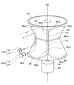
- FIG. 2 is a schematic configuration diagram of a laser radar LR using a mirror unit.
- FIG. 3 is a sectional view of the mirror unit MU in the laser radar LR, but the light projecting system and the light receiving system are omitted.
- the laser radar LR for example, a pulse-type semiconductor laser LD that emits a laser beam, a collimator lens CL that converts divergent light from the semiconductor laser LD into parallel light, and laser light that is collimated by the collimator lens CL,
- the mirror unit MU that reflects the reflected light from the scanned object OBJ while scanning and projecting toward the object OBJ side (FIG. 1) by the rotating mirror surface, and the object reflected by the mirror unit MU It has a lens LS that collects the reflected light from the object OBJ, and a photodiode PD that receives the light collected by the lens LS.
- the mirror unit MU has a shape in which two substantially polygonal frustums are joined in opposite directions and integrated, that is, has four pairs of mirror surfaces M1 and M2 that are inclined to face each other in pairs.
- the mirror surfaces M1 and M2 constituting the first reflecting surface and the second reflecting surface are formed from a resin integrally molded product having the shape of the mirror unit MU, as will be described in detail later.
- the mirror unit MU is generally hollow and has a plate-like flange portion FL extending in the horizontal direction at the center.
- a circular opening CH is formed at the center of the flange portion FL.
- the flange portion FL is sandwiched between the plate-like first holding portion PT1 and the second holding portion PT2.
- the first holding part PT1 disposed below the flange part FL is configured to rotate integrally with the outer periphery of the first holding part PT1 contacting the inner periphery of the mirror unit MU almost entirely.
- An opening PT1a having a non-circular cross section is formed at the center of the lower surface of the first holding part PT1, and the tip of the rotation shaft SH of the motor MT is fitted and connected to the first holding part PT1 so as to rotate integrally.
- the opening PT1a and the rotation shaft SH may be fitted by press-fitting.
- a motor MT as a rotational drive source is fixed to a frame FR that holds a laser radar LR.
- a cylindrical shaft PT1b is implanted in the center of the upper surface of the first holding portion PT1 so as to be coaxial with the rotation shaft SH, and extends upward through the circular opening CH of the flange portion FL. It passes through a circular opening PT2a formed at the center of the plate-like second holding part PT2.
- the tip of the cylindrical shaft PT1b is fitted into the cap CP by press fitting or the like.
- the spring SPG disposed between the cap CP and the second holding part PT2 urges the cap CP in the direction of separating the second holding part PT2, and the reaction force exerts on the cylindrical shaft PT1b.
- the first holding portion PT1 is in close contact with the flange portion FL by being transmitted through the flange portion FL. Since it is configured as described above, when power is supplied to the motor MT from a power supply (not shown), the rotation shaft SH rotates and the mirror unit MU is driven to rotate via the first holding part PT1. It has become.
- a convex portion PJ is formed on the outer periphery of the lower end of the mirror unit MU.
- a reflection portion is formed on the end surface of the convex portion PJ.
- a sensor SS that can detect the passage of the convex portion PJ by projecting detection light and measuring the reflection amount thereof is installed. Therefore, by reading the output of the sensor SS, the rotational speed of the mirror unit MU can be obtained, and thereby the output of the motor MT can be feedback controlled using a control device (not shown).
- the detection mode of the rotational speed of the mirror unit MU is not limited to the above.
- a concave portion may be provided instead of the convex portion, but these are preferably formed simultaneously with the formation of the mirror unit.
- the convex portion PJ may be provided on the upper end side of the mirror unit MU.
- the semiconductor laser LD and the collimating lens CL constitute a light projecting system LPS
- the lens LS and the photodiode PD constitute a light receiving system RPS.
- the optical axes of the light projecting system LPS and the light receiving system RPS are orthogonal to the rotation axis RO of the mirror unit MU.
- the divergent light intermittently emitted in a pulse form from the semiconductor laser LD is converted into a parallel light beam by the collimator lens CL, and is incident on the first mirror surface M1 of the rotating mirror unit MU, where After being reflected and further reflected by the second mirror surface M2, it is scanned and projected as a laser spot light having, for example, a vertically long rectangular cross section on the external object OBJ side.
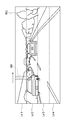
- FIG. 4 is a diagram showing a state in which the laser spot light SB (shown by hatching) emitted in accordance with the rotation of the mirror unit MU scans within the detection range RG of the laser radar LR.
- the crossing angles are different from each other.
- the laser light is sequentially reflected by the rotating first mirror surface M1 and second mirror surface M2.
- the laser light reflected by the first pair of the first mirror surface M1 and the second mirror surface M2 moves horizontally from left to right in the uppermost region Ln1 of the detection range RG according to the rotation of the mirror unit MU. Is scanned.
- the laser light reflected by the second pair of the first mirror surface M1 and the second mirror surface M2 is left in the second region Ln2 in the horizontal direction from the top of the detection range RG according to the rotation of the mirror unit MU.
- the laser beam reflected by the third pair of the first mirror surface M1 and the second mirror surface M2 is left in the third region Ln3 from the top of the detection range RG in the horizontal direction according to the rotation of the mirror unit MU.
- the laser beam reflected by the fourth pair of the first mirror surface M1 and the second mirror surface moves horizontally from left to right in the lowermost region Ln4 of the detection range RG according to the rotation of the mirror unit MU. Is scanned.
- a part of the laser beam reflected by the object OBJ out of the scanned and projected light beam is incident again on the second mirror surface M2 of the mirror unit MU, reflected there, and further reflected by the first mirror.
- the light is reflected by the surface M1, collected by the lens LS, and detected by the light receiving surface of the photodiode PD.
- the object OBJ can be detected in the entire region within the detection range RG.
- FIG. 5 is a cross-sectional view of a molding apparatus according to this embodiment for molding a molded product for forming a mirror unit
- FIG. 6 is a cross-sectional view showing the main part of the molding apparatus
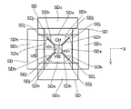
- FIG. It is the figure which looked at the state (Drawing 5) which clamped a model and a slide type from the fixed mold side.
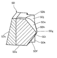
- FIG. 8 is a view of the slide mold of FIG. 7 cut along the line VIII-VIII and viewed in the direction of the arrow, but shows only a part of the holder.
- the “range where the first base surface or the second base surface interferes with the slide mold when the molded product is taken out after molding” is, for example, “the mold opening / closing direction on the first base surface or the second base surface of the molded product” The distance along the sliding direction between one end of the head and the other end on the opposite side (L to be described later).
- a fixed FD is mounted on a base BS fixed on a surface plate (not shown), and an opening BSa is formed corresponding to an angular pin AP described later.
- the movable MD is arranged to be movable in the vertical direction by a drive source (not shown).
- four slide molds SD are arranged to be movable in the horizontal direction with respect to the fixed mold FD.
- the vertical direction is the Z direction
- the horizontal direction (sliding direction) is the X direction or the Y direction (only the X direction is shown in FIGS. 5 and 6).
- the fixed mold FD is formed at the center of a substantially square frustum-shaped inner peripheral transfer surface FDa, a flat flange transfer surface FDb provided on the top of the inner peripheral transfer surface FDa, and the flange transfer surface FDb. And a cylindrical transfer portion FDc. Further, a guide surface FDd for guiding the slide mold SD is formed around the inner peripheral transfer surface FDa of the fixed mold FD.
- the fixed mold FD has a transfer portion for forming the convex portion PJ of the mirror unit MU.
- the movable MD includes a substantially square frustum-shaped inner peripheral transfer surface MDa, a planar flange transfer surface MDb provided on the top of the inner peripheral transfer surface MDa, and an upper end of the movable MD to the flange transfer surface MDb. It has four pin gate portions MDc in communication.
- the pin gate portions MDc are arranged at equal intervals in the circumferential direction at equal distances from the center of the flange transfer surface MDb. More specifically, as shown in FIG. 7, the pin gate portions MDc correspond to the boundary portions of the adjacent slide type SD. Are located at intermediate positions.
- the movable MD is held by the support block STB, and the support block STB is fixed to the plate part PT, and these move integrally in the Z direction.
- a concave portion CC is formed on the lower surface of the plate portion PT so as to be shielded by the upper surface from which the pin gate portion MDc of the support block STB is exposed.
- the sprue portion SL penetrates the support portion SP and communicates with the concave portion CC.
- the formed sprue portion SL is connected to a resin supply source (not shown).
- the locking block LB is directed toward the fixed die FD and the through hole LBa inclined so as to be separated from the axis AX (FIG. 6) of the movable MD as it goes toward the fixed die FD.
- a tapered surface LBb inclined so as to be separated from the axis AX (FIG. 6) of the movable MD.
- a cylindrical angular pin AP is inserted from above in the through hole LBa, and its lower end side is exposed from the locking block LB.
- the exposed angular pins AP are inclined at the same angle so as to move away from the axis AX (FIG. 6) of the movable type MD toward the fixed type FD.
- each of the four slide types SD has a main core SDa, a sub-core SDb, and a holder SDc for fixing and holding the main core SDa and the sub-core SDb.
- the holder SDc is formed along an inclined cylindrical hole SDd (FIG. 5) capable of receiving the angular pin AP, a tapered surface SDu inclined corresponding to the tapered surface LBb of the locking block LB, and an edge facing the tapered surface SDu.
- a protruding guide part SDv has a function of guiding the approaching locking block LB.
- the holder SDc is movable by engaging with a guide provided on the guide surface FDd of the fixed mold FD.
- the main core SDa integrally formed of stainless steel or the like has a first plane (first transfer surface) SDe inclined with respect to the axis AX (FIG. 6) of the movable MD and the opposite side of the first plane SDe.
- It has one connecting surface transfer surface SDh (only one is shown in FIG. 8) and a second connecting surface transfer surface SDi (only one is shown in FIG. 8) formed adjacent to both sides of the second plane SDf.
- the first joint surface transfer surface SDh and the second joint surface transfer surface SDi are preferably concave curved surfaces.
- the shapes of the four main cores SDa are different from each other. More specifically, the first plane SDe is inclined at 45 degrees with respect to the axis AX, but the inclination angle (crossing angle) of the second plane SDf with respect to the first plane SDe is, for example, 88 degrees or 90 degrees. , 92 degrees and 94 degrees. In addition, although the selection of the inclination angle is arbitrary, in order to measure the object OBJ three-dimensionally, it is preferable that the angles are different from each other by 0.5 degrees or more. The areas of the first plane SDe and the second plane SDf are preferably equal, but may be different within ⁇ 20%.
- the secondary core SDb has a spherical first outer peripheral surface SDj (only one is shown in FIG. 8) adjacent to the first plane SDe and a spherical second outer peripheral surface SDk (FIG. 8) adjacent to the second plane SDf. Then, only one of them is shown).
- the slide type SD can slide in the X direction beyond the distance L along the X direction between the upper end P1 and the lower end P2 of the inclined first plane SDe. It has become. The same applies to the slide type SD arranged in the Y direction.
- the tip of the angular pin AP penetrating the cylindrical hole SDd of the slide type SD enters the opening BSa of the base BS.
- the slide amount of the slide type SD can be secured.
- the resin is evenly supplied from the concave portion CC into the four pin gate portions MDc, and the fixed mold FD, the movable mold MD, Resin is supplied into a sealed cavity CV formed by the slide mold SD.
- the inner peripheral transfer surface FDa of the fixed mold FD forms an inner peripheral surface on one side of the molded product MP (the same shape as the mirror unit MU), and the lower surface of the flange portion FL is formed by the flange transfer surface FDb.
- a circular opening CH of the flange portion FL is formed by the cylindrical transfer portion FDc, and a convex portion PJ (see FIG. 3) is formed by a transfer portion (not shown).
- the inner peripheral transfer surface MDa of the movable mold MD forms the other inner peripheral surface of the molded product MP
- the flange transfer surface MDb forms the upper surface of the flange portion FL.
- the center of gravity G see FIG.
- the center of gravity G is in the circular opening CH, preferably the center of the circular opening CH.
- the center of gravity of the molded product MP can be adjusted by adjusting the positions of the fixed mold FD, the movable mold MD, and the slide mold SD at the time of clamping.
- the first base surface is formed by the first plane SDe of the main core SDa of the slide type SD
- the second base surface is formed by the second plane SDf
- the connecting surface MUe is formed by the intermediate surface SDg.
- a curved or chamfered first connecting surface MUa is formed by the first connecting surface transfer surface SDh
- a curved or chamfered second connecting surface MUb is formed by the second connecting surface transfer surface SDi. 2
- the first outer peripheral surface SDj forms a spherical first outer peripheral surface MUc
- the second outer peripheral surface SDk forms a spherical second outer peripheral surface MUd.
- the first outer peripheral surface MUc and the second outer peripheral surface MUd can reduce the size of the mirror unit MU and reduce the rotational resistance.
- the first connecting surfaces MUa adjacent in the circumferential direction and the second connecting surfaces MUb adjacent in the circumferential direction form a parting line PTL (see FIG. 2) of the slide type SD between them.
- the first outer peripheral surfaces MUc adjacent in the circumferential direction and the second outer peripheral surfaces MUd adjacent in the circumferential direction are connected with almost no step.
- the connecting surface MUe serving as the outer periphery of the flange portion FL has an arcuate cross section. Thereby, the 1st foundation surface and 2nd foundation surface which became a pair come to connect smoothly.
- the slide mold SD is moved outward. Since the slide is possible and the angular pin AP is retracted from the opening BSa and pushes the holder SDc of the slide type SD outward, the slide type SD moves in the X direction and the Y direction which are separated from the fixed type FD. When the angular pin AP is removed from the cylindrical hole SDd, the slide die SD stops. In this state, the distance L (FIG.
- a metal film (Al, Ag, etc.) is formed on the first base surface and the second base surface by vacuum deposition or the like as a post-molding process.
- the first mirror surface M1 and the second mirror surface M2 can be formed, whereby the mirror unit MU shown in FIGS. 2 and 3 can be formed.
- the relative tilt angle between the first mirror surface M1 and the second mirror surface M2 is preferably 45 degrees or more and 135 degrees or less.
- the mirror unit MU can be assembled to the laser radar LR so as to connect the rotation shaft SH of the motor MT via the first holding part PT1 and the second holding part PT2.
- the upper surface or the lower surface of the flange portion FL can be used as a reference surface for assembly.
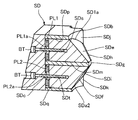
- FIG. 9 is a perspective view of a cross section of the mold similar to that of FIG. 8 of the slide type SD according to the modification of the present embodiment.
- the sub-core SDb has two openings SDp and SDq partitioned by the partition wall SDm, and the tip of the partition wall SDm is the intermediate surface SDg.
- One opening SDp partitioned by the partition wall SDm is closed by a holder SDc.
- a first adjustment plate PL1 having a first opening PL1a is disposed in contact with the holder SDc in the opening SDp, and the first core member (first mold part) SDa1 is transferred to the first plane SDe and the first connection.
- the surface SDh is disposed so as to be exposed in the opening SDp.
- the first core member SDa1 has first screw holes SDs formed on the first adjustment plate PL1 side.
- the first core member SDa1 is inserted by inserting the bolt BT from the holder SDc side, passing through the first opening PL1a of the first adjustment plate PL1, and screwing into the first screw hole SDs of the first core member SDa1. , Fixed to the holder SDc.
- the other opening SDq partitioned by the partition wall SDm is similarly closed by the holder SDc.
- a second adjustment plate PL2 having a second opening PL2a is disposed so as to contact the holder SDc in the opening SDq, and the second core member (second mold part) SDa2 is transferred to the second plane SDf and the second connection.
- the surface SDi is disposed in the opening SDq so as to be exposed.
- the second core member SDa2 has a second screw hole SDt on the second adjustment plate PL2 side.
- the second core member SDa2 is inserted by inserting the bolt BT from the holder SDc side, passing through the second opening PL2a of the second adjustment plate PL2, and screwing into the second screw hole SDt of the second core member SDa2. , Fixed to the holder SDc.
- the first base surface is formed by the first plane SDe
- the second base plane is formed by the second plane SDf
- the connecting surface MUe is formed by the intermediate plane SDg
- the first connecting surface MUa is formed by the first connecting surface transfer surface SDh
- the second connecting surface MUb is formed by the second connecting surface transfer surface SDi.
- the protrusion amount of the first core member SDa1 can be changed by changing the thickness of the first adjustment plate PL1, and independently of this, the thickness of the second adjustment plate PL2 Can be changed to change the protruding amount of the second core member SDa2.
- the present invention is not limited to the embodiments described in the present specification, and includes other embodiments and modifications based on the embodiments and technical ideas described in the present specification. It is obvious to For example, in the above-described embodiment, the number (N) of the slide type SD is four, but may be three, or may be five or more.
- the angles of the first base surface with respect to the axis may be made different from each other, and the angles of the second base surface may be made equal to each other, or the angles of the first base surface and the second base surface may be made different. May be allowed.
- the first base surface and the second base surface are not limited to flat surfaces, and may be curved surfaces.
Landscapes
- Engineering & Computer Science (AREA)
- Manufacturing & Machinery (AREA)
- Mechanical Engineering (AREA)
- Moulds For Moulding Plastics Or The Like (AREA)
Abstract
La présente invention concerne un dispositif de moulage qui est apte à une production à grande échelle tout en permettant de fabriquer une unité miroir ayant une bonne précision, un produit moulé, une unité miroir, et un procédé de moulage. Dans la présente invention, une fois une résine solidifiée, lorsqu'une matrice mobile MD est séparée par rapport à une filière fixe, une tige angulaire AP pousse un support SDc d'une matrice coulissante SD vers l'extérieur tout en se rétractant par rapport à une ouverture BSa, et par conséquent se déplace dans une direction X et une direction Y dans laquelle la matrice coulissante SD se sépare de la filière fixe FD. La matrice coulissante SD s'arrête au moment où la tige angulaire AP sort d'un trou cylindrique SDd, mais dépasse une distance L correspondant à une partie en contre-dépouille d'un produit moulé MP dans cet état, et la matrice coulissante SD s'est déplacée d'une distance suffisante pour extraire le produit moulé, et le produit moulé peut ainsi être extrait.
Priority Applications (1)
| Application Number | Priority Date | Filing Date | Title |
|---|---|---|---|
| JP2017528330A JP6711357B2 (ja) | 2015-07-14 | 2016-06-08 | 成形装置及び成形方法 |
Applications Claiming Priority (2)
| Application Number | Priority Date | Filing Date | Title |
|---|---|---|---|
| JP2015-140163 | 2015-07-14 | ||
| JP2015140163 | 2015-07-14 |
Publications (1)
| Publication Number | Publication Date |
|---|---|
| WO2017010197A1 true WO2017010197A1 (fr) | 2017-01-19 |
Family
ID=57756921
Family Applications (1)
| Application Number | Title | Priority Date | Filing Date |
|---|---|---|---|
| PCT/JP2016/067008 Ceased WO2017010197A1 (fr) | 2015-07-14 | 2016-06-08 | Dispositif de moulage, produit moulé, unité miroir et procédé de moulage |
Country Status (2)
| Country | Link |
|---|---|
| JP (1) | JP6711357B2 (fr) |
| WO (1) | WO2017010197A1 (fr) |
Cited By (1)
| Publication number | Priority date | Publication date | Assignee | Title |
|---|---|---|---|---|
| WO2019123722A1 (fr) * | 2017-12-22 | 2019-06-27 | コニカミノルタ株式会社 | Dispositif de balayage optique, procédé de commande de dispositif de balayage optique et programme de commande de dispositif de balayage optique |
Families Citing this family (1)
| Publication number | Priority date | Publication date | Assignee | Title |
|---|---|---|---|---|
| KR102438563B1 (ko) * | 2022-06-22 | 2022-09-01 | 허만우 | 금형의 가이드핀리스 제로가이드블록 구조 |
Citations (5)
| Publication number | Priority date | Publication date | Assignee | Title |
|---|---|---|---|---|
| JPH03130715A (ja) * | 1989-10-16 | 1991-06-04 | Fujitsu Ltd | 回転多面鏡の製造方法 |
| JPH06331918A (ja) * | 1993-05-19 | 1994-12-02 | Ricoh Co Ltd | 回転多面鏡およびこれを備える光走査装置 |
| JP2001341165A (ja) * | 2000-05-30 | 2001-12-11 | Sekisui Chem Co Ltd | 射出成形用金型 |
| JP2007237665A (ja) * | 2006-03-10 | 2007-09-20 | Matsushita Electric Ind Co Ltd | 樹脂成型体の製造方法 |
| WO2014168137A1 (fr) * | 2013-04-11 | 2014-10-16 | コニカミノルタ株式会社 | Système optique de balayage et radar |
Family Cites Families (1)
| Publication number | Priority date | Publication date | Assignee | Title |
|---|---|---|---|---|
| JP4982290B2 (ja) * | 2007-08-06 | 2012-07-25 | 富士フイルム株式会社 | 成形機 |
-
2016
- 2016-06-08 JP JP2017528330A patent/JP6711357B2/ja active Active
- 2016-06-08 WO PCT/JP2016/067008 patent/WO2017010197A1/fr not_active Ceased
Patent Citations (5)
| Publication number | Priority date | Publication date | Assignee | Title |
|---|---|---|---|---|
| JPH03130715A (ja) * | 1989-10-16 | 1991-06-04 | Fujitsu Ltd | 回転多面鏡の製造方法 |
| JPH06331918A (ja) * | 1993-05-19 | 1994-12-02 | Ricoh Co Ltd | 回転多面鏡およびこれを備える光走査装置 |
| JP2001341165A (ja) * | 2000-05-30 | 2001-12-11 | Sekisui Chem Co Ltd | 射出成形用金型 |
| JP2007237665A (ja) * | 2006-03-10 | 2007-09-20 | Matsushita Electric Ind Co Ltd | 樹脂成型体の製造方法 |
| WO2014168137A1 (fr) * | 2013-04-11 | 2014-10-16 | コニカミノルタ株式会社 | Système optique de balayage et radar |
Cited By (3)
| Publication number | Priority date | Publication date | Assignee | Title |
|---|---|---|---|---|
| WO2019123722A1 (fr) * | 2017-12-22 | 2019-06-27 | コニカミノルタ株式会社 | Dispositif de balayage optique, procédé de commande de dispositif de balayage optique et programme de commande de dispositif de balayage optique |
| JPWO2019123722A1 (ja) * | 2017-12-22 | 2021-01-14 | コニカミノルタ株式会社 | 光走査装置、光走査装置の制御方法、および光走査装置の制御プログラム |
| JP7078061B2 (ja) | 2017-12-22 | 2022-05-31 | コニカミノルタ株式会社 | 光走査装置、光走査装置の制御方法、および光走査装置の制御プログラム |
Also Published As
| Publication number | Publication date |
|---|---|
| JP6711357B2 (ja) | 2020-06-17 |
| JPWO2017010197A1 (ja) | 2018-04-26 |
Similar Documents
| Publication | Publication Date | Title |
|---|---|---|
| US10288723B2 (en) | Mirror unit, distance measurement device and laser radar, and mobile body and fixed object having the mirror unit and the distance measurement device or the laser radar | |
| EP3330766B1 (fr) | Unité miroir et dispositif de détection d'objet de type à balayage optique | |
| EP3101477B1 (fr) | Dispositif d'impression 3d du type à photo-durcissement et son système d'exposition d'images | |
| TWI760620B (zh) | 造形裝置及造形方法 | |
| CN111168066B (zh) | 造形装置及造形方法 | |
| TWI688757B (zh) | 具有自動對準系統及干涉儀之眼用裝置的線上檢測設備 | |
| JP5809498B2 (ja) | 光源ユニットの調整装置及び製造方法 | |
| CN118635656A (zh) | 加工装置以及方法 | |
| JP6711357B2 (ja) | 成形装置及び成形方法 | |
| CN118893302A (zh) | 处理系统及处理方法 | |
| JP7699954B2 (ja) | 光学装置、車載システム、移動装置、および光学装置の製造方法 | |
| JP6601498B2 (ja) | 成形装置 | |
| JP2006058860A5 (fr) | ||
| JP2014115370A (ja) | 走査レンズおよび走査レンズの製造方法 | |
| US20140160447A1 (en) | Image display device | |
| US11813740B2 (en) | Camera and robot system | |
| US7327522B2 (en) | Optical lens and method of manufacturing the same | |
| JP4943495B2 (ja) | 光学素子成型装置 | |
| JP2006309121A (ja) | 位置決め構造 | |
| US20060250931A1 (en) | Optical lens and method of manufacturing the same | |
| CN111670399B (zh) | 激光微镜阵列中的耦合和同步镜元件 | |
| JP2006289692A (ja) | 鏡面駒の作製方法、光学素子の製造方法、光学素子 | |
| JP2006091328A (ja) | 非球面プラスチックレンズおよび金型 | |
| JP3922383B2 (ja) | 光走査装置 | |
| CN120970491A (zh) | 测量系统 |
Legal Events
| Date | Code | Title | Description |
|---|---|---|---|
| 121 | Ep: the epo has been informed by wipo that ep was designated in this application |
Ref document number: 16824177 Country of ref document: EP Kind code of ref document: A1 |
|
| ENP | Entry into the national phase |
Ref document number: 2017528330 Country of ref document: JP Kind code of ref document: A |
|
| NENP | Non-entry into the national phase |
Ref country code: DE |
|
| 122 | Ep: pct application non-entry in european phase |
Ref document number: 16824177 Country of ref document: EP Kind code of ref document: A1 |