WO2019123722A1 - Dispositif de balayage optique, procédé de commande de dispositif de balayage optique et programme de commande de dispositif de balayage optique - Google Patents
Dispositif de balayage optique, procédé de commande de dispositif de balayage optique et programme de commande de dispositif de balayage optique Download PDFInfo
- Publication number
- WO2019123722A1 WO2019123722A1 PCT/JP2018/031799 JP2018031799W WO2019123722A1 WO 2019123722 A1 WO2019123722 A1 WO 2019123722A1 JP 2018031799 W JP2018031799 W JP 2018031799W WO 2019123722 A1 WO2019123722 A1 WO 2019123722A1
- Authority
- WO
- WIPO (PCT)
- Prior art keywords
- polygon mirror
- light
- rotation angle
- scanning device
- laser light
- Prior art date
- Legal status (The legal status is an assumption and is not a legal conclusion. Google has not performed a legal analysis and makes no representation as to the accuracy of the status listed.)
- Ceased
Links
Images




Classifications
-
- G—PHYSICS
- G01—MEASURING; TESTING
- G01S—RADIO DIRECTION-FINDING; RADIO NAVIGATION; DETERMINING DISTANCE OR VELOCITY BY USE OF RADIO WAVES; LOCATING OR PRESENCE-DETECTING BY USE OF THE REFLECTION OR RERADIATION OF RADIO WAVES; ANALOGOUS ARRANGEMENTS USING OTHER WAVES
- G01S7/00—Details of systems according to groups G01S13/00, G01S15/00, G01S17/00
- G01S7/48—Details of systems according to groups G01S13/00, G01S15/00, G01S17/00 of systems according to group G01S17/00
- G01S7/481—Constructional features, e.g. arrangements of optical elements
-
- G—PHYSICS
- G01—MEASURING; TESTING
- G01S—RADIO DIRECTION-FINDING; RADIO NAVIGATION; DETERMINING DISTANCE OR VELOCITY BY USE OF RADIO WAVES; LOCATING OR PRESENCE-DETECTING BY USE OF THE REFLECTION OR RERADIATION OF RADIO WAVES; ANALOGOUS ARRANGEMENTS USING OTHER WAVES
- G01S7/00—Details of systems according to groups G01S13/00, G01S15/00, G01S17/00
- G01S7/48—Details of systems according to groups G01S13/00, G01S15/00, G01S17/00 of systems according to group G01S17/00
- G01S7/483—Details of pulse systems
- G01S7/484—Transmitters
-
- G—PHYSICS
- G02—OPTICS
- G02B—OPTICAL ELEMENTS, SYSTEMS OR APPARATUS
- G02B26/00—Optical devices or arrangements for the control of light using movable or deformable optical elements
- G02B26/08—Optical devices or arrangements for the control of light using movable or deformable optical elements for controlling the direction of light
- G02B26/10—Scanning systems
- G02B26/12—Scanning systems using multifaceted mirrors
Definitions
- the present invention relates to an optical scanning device, a control method of the optical scanning device, and a control program of the optical scanning device.
- the optical scanning device emits laser light toward the measurement space, and measures the distance to an object in the measurement space from the time from the emission to reception of the reflected light.
- a polygon mirror is provided as an optical scanning means, laser light is reflected by the rotating polygon mirror to scan the measurement space, and the reflected light from the object is received by a light receiving means such as a photodiode. doing.
- the light scanning device Since the light scanning device has a constant pulse light emission period, basically, if the polygon mirror in the light scanning device is rotated at a constant speed, the scanning angle is determined from the reference position for starting the light beam scanning. Can.
- Some conventional optical scanning devices scan a laser beam so as to form a fan-shaped plane perpendicular to the road surface, and receive a reflection from a road surface and a moving object on the road, thereby moving the moving object. There is a device to detect. In such an optical scanning device, the scanning angle is calculated based on the time which is assumed to be perpendicular to the road surface after the start of the irradiation of the laser light.
- the optical scanning device may be inclined due to a time change or the like at the time of installation or after installation.
- the laser beam is not perpendicular to the road surface in a time when it is originally supposed to be perpendicular to the road surface, and an error occurs in the obtained scanning angle.
- a scanning start detection means for detecting the reference position of the scanning start of the light beam is provided, while another part along the light scanning direction of the light beam on the road surface
- a light receiving signal obtained by receiving the reflected light from the differentiating means by the light receiving means with a differentiating means for differentiating so that the reflected light quantity or the light emitting / receiving time is different from the part, and a light reception signal obtained by the light receiving means
- the scanning angle of the light beam is corrected based on the scanning start detection signal (Japanese Patent Application Laid-Open No. 10-253910).
- the prior art corrects the scanning angle, it places the differentiating means for differentiating the reflected light amount on the road surface of the road, and corrects it based on the reflected light from the differentiating means. There is. For this reason, in the prior art, correction can not be performed unless the reflected light from the differentiating means is detected, so that it is not possible to immediately correct the error in the scanning angle caused by the vibration applied to the device suddenly.
- the present invention has been made in view of the above-described circumstances, and an object of the present invention is to provide an optical scanning device capable of immediately correcting an error even when vibration is added and an error occurs in a scanning angle. It is.
- Another object of the present invention is to provide a control method of an optical scanning device capable of correcting the error immediately even when the vibration causes an error in the scanning angle.
- Another object of the present invention is to provide a control program of an optical scanning device capable of correcting the error immediately even when the vibration causes an error in the scanning angle.
- a laser light source for emitting pulsed laser light;
- a polygon mirror having at least one mirror surface for reflecting the laser light and scanning in the measurement space;
- a photodiode for receiving light reflected from an object in the measurement space;
- a motor for rotating the polygon mirror;
- a motor encoder for detecting a rotation angle of the motor;
- a polygon mirror rotation angle detection unit that detects a rotation angle of the polygon mirror;
- a control unit that controls the light emission timing of the laser light according to the rotational phase difference between the motor and the polygon mirror obtained from the signals of the motor encoder and the polygon mirror rotation angle detection unit;
- An optical scanning device for emitting pulsed laser light;
- a polygon mirror having at least one mirror surface for reflecting the laser light and scanning in the measurement space;
- a photodiode for receiving light reflected from an object in the measurement space;
- a motor for rotating the polygon mirror;
- a motor encoder for detecting a rotation angle of the motor;
- a polygon mirror rotation angle detection unit
- the control unit At the start of emission of the laser beam corresponding to the mirror surface, the control unit The light emission timing of the laser light is controlled to emit the laser light in synchronization with the signal from the motor encoder after a predetermined period has elapsed since the signal from the polygon mirror rotation angle detection unit is received.
- the optical scanning device as described in (1).
- the control unit is configured to reflect the laser light on the mirror surface and scan the mirror The light scanning device according to (1) or (2), wherein the light emission timing of the laser light is controlled so as to emit the laser light simultaneously with receiving a signal from the polygon mirror rotation angle detection unit.
- the resolution of the motor encoder is equal to or smaller than the scanning resolution of the laser beam scanned by the polygon mirror,
- the optical scanning device according to any one of the above (1) to (3), wherein the resolution of the polygon mirror rotation angle detection unit is smaller than the resolution of the motor encoder.
- control unit prevents the light emission interval of the laser light from becoming equal to or less than a predetermined interval determined in advance.
- the polygon mirror rotation angle detection unit with photo interrupter The light scanning device according to any one of (1) to (5), further including: a pin provided on the polygon mirror and blocking a light of the photo interrupter by rotation of the polygon mirror.
- a laser light source for emitting pulsed laser light;
- a polygon mirror having at least one mirror surface for reflecting the laser light and scanning in the measurement space;
- a photodiode for receiving light reflected from an object in the measurement space;
- a motor for rotating the polygon mirror;
- a motor encoder for detecting a rotation angle of the motor;
- a polygon mirror rotation angle detection unit that detects a rotation angle of the polygon mirror.
- the emission timing of the laser beam is controlled to emit the laser beam in synchronization with the signal from the motor encoder after a predetermined period has elapsed.
- the control method of the optical scanning device as described in 4.
- the resolution of the motor encoder is equal to or smaller than the scanning resolution of the laser beam scanned by the polygon mirror,
- the polygon mirror rotation angle detection unit With photo interrupter, The control method of the optical scanning device according to any one of (7) to (11), further including a pin provided on the polygon mirror and blocking a light of the photo interrupter by rotation of the polygon mirror.
- a control program of a light scanning device for causing a computer to execute the control method of a light scanning device according to any one of (7) to (12).
- laser light is reflected by the polygon mirror to scan the inside of the measurement space two-dimensionally, while the reflected light from an object or the like is reflected again by the polygon mirror and guided to the photodiode.
- the obtained information is referred to as a distance image, and includes information on the direction of the object as viewed from the laser light transmitting / receiving unit and the distance to the object.
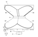
- FIG. 1 is a cross-sectional view showing an optical scanning device according to the present embodiment.
- the light scanning device 10 includes a light emitting and receiving unit 11 and a control unit 12, and is housed in a housing 57.
- the light emitting and receiving unit 11 includes a semiconductor laser 51, a collimator lens 52, a polygon mirror 53, a lens 54, a photodiode 55, and a motor 56.
- the motor 56 is provided with a motor encoder 61 for detecting the rotational angle of the motor 56.
- the polygon mirror 53 is provided with a polygon mirror rotation angle detection unit 71 that detects the rotation angle of the polygon mirror 53.
- the control unit 12 obtains distance information (distance value) according to the time difference from the light emission of the semiconductor laser 51 to the light reception of the photodiode 55. From the obtained distance information, a distance image composed of a plurality of pixels indicating the distribution of distance values to the object in the measurement space is generated. The distance image is also referred to as distance measurement point cloud data or a distance map. Further, as described later, the control unit 12 also controls the rotation of the motor 56 constituting the light emitting and receiving unit 11 and the light emission timing of the laser light.
- FIG. 2 is a block diagram showing the configuration of the control unit 12.
- the control unit 12 is a computer, and is provided with a CPU 121 which is an arithmetic device, a RAM 122 used as a work area or temporary storage, a ROM 123 storing basic programs, and as necessary, and stores programs and parameter data.
- a nonvolatile memory 124 is provided and connected to one another by a bus 120.
- Such a configuration of the control unit 12 is the same as that of a known computer, and thus the detailed description is omitted. However, each control is performed by the CPU 121 executing a program for performing a control method described later.
- the configuration of the control unit 12 as a computer may be configured by, for example, a circuit such as a field-programmable gate array (FPGA) or an application specific integrated circuit (ASIC).
- FPGA field-programmable gate array
- ASIC application specific integrated circuit
- the light emitting and receiving unit 11 is connected to the control unit 12 through the bus 120 (directly or through an interface for connecting an external device).
- control unit 12 controls the rotational speed of the motor 56 by the signals from the motor encoder 61 and the polygon mirror rotational angle detection unit 71. Further, the control unit 12 controls the light emission timing of the laser beam emitted by the semiconductor laser 51 according to the rotational phase difference between the motor 56 and the polygon mirror 53 obtained from the signals from the motor encoder 61 and the polygon mirror rotation angle detection unit 71. Yes (more on this later).
- the semiconductor laser 51 is a laser light source, and emits pulsed laser light.
- the collimator lens 52 converts divergent light from the semiconductor laser 51 into parallel light.
- the polygon mirror 53 scans and projects the laser light collimated by the collimator lens 52 toward the measurement space by the rotating mirror surface (described later), and reflects the reflected light from the object.
- the lens 54 condenses the reflected light from the object reflected by the polygon mirror 53.
- the photodiode 55 receives the light collected by the lens 54, and has a plurality of pixels arranged in the Z direction.
- the motor 56 rotationally drives the polygon mirror 53.
- the semiconductor laser 51 and the collimator lens 52 constitute an emitting unit 501, and the lens 54 and the photodiode 55 constitute a light receiving unit 502. It is preferable that the optical axes of the light emitting unit 501 and the light receiving unit 502 be orthogonal to the polygon mirror rotation shaft 530.
- the box-like housing 57 is fixed to a part of the vehicle 100.
- the housing 57 includes an upper wall 57a, a lower wall 57b opposite to the upper wall 57a, and a side wall 57c connecting the upper wall 57a and the lower wall 57b.
- An opening 57d is formed in part of the side wall 57c, and a transparent plate 58 is attached to the opening 57d.
- the polygon mirror 53 has at least one mirror surface. In this embodiment, eight mirror surfaces are provided.
- the polygon mirror 53 is connected to the motor shaft 56 a of the motor 56 fixed to the housing 57 and is rotationally driven.
- the axis (rotational axis) of the motor shaft 56a extends in the Z direction, which is the vertical direction, and the XY plane formed by the X direction and the Y direction orthogonal to the Z direction is a horizontal plane.
- the axis of the motor shaft 56a may be inclined relative to the vertical direction.
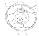
- FIG. 3 is a front view of the polygon mirror 53
- FIG. 4 is a perspective view of the polygon mirror 53 viewed from the bottom direction
- FIG. 5 is a sectional view of the polygon mirror 53. As shown in FIG.
- the polygon mirror 53 has a shape in which two square pyramids are joined in opposite directions and integrated. Therefore, it has four pairs of mirror surfaces that are inclined in the opposite directions. As a pair of mirror surfaces, a first mirror surface M1 and a second mirror surface M2, a third mirror surface M3 and a fourth mirror surface M4 (surface not shown in FIG. 1), a fifth mirror surface M5 and a sixth mirror surface M6 A seventh mirror surface M7 and an eighth mirror surface M8 (surface not shown in FIG. 1).
- the first mirror surface M1, the third mirror surface M3, the fifth mirror surface M5, and the seventh mirror surface M7 have different inclination angles ⁇ with respect to the polygon mirror rotation axis 530.
- the second mirror surface M2, the fourth mirror surface M4, the sixth mirror surface M6, and the eighth mirror surface M8 have different inclination angles ⁇ with respect to the polygon mirror rotation axis 530.
- the inclination angles are angles ⁇ and ⁇ formed by the extension of each mirror surface and the portion where the extension intersects the polygon mirror rotation axis 530.
- FIG. 1 the inclination angle ⁇ of the first mirror surface M1 and the inclination angle ⁇ of the second mirror surface M2 are shown, but the same applies to other mirror surfaces (however, the inclination angle itself is the mirror surface as described above) Every different).
- each mirror surface is described generically or not distinguished, it is referred to as a mirror surface M.
- Each of these mirror surfaces M is formed by vapor deposition of a reflective film on the surface of a resin material (for example, PC (polycarbonate)) in the shape of the polygon mirror 53.
- a resin material for example, PC (polycarbonate)
- a ring member 75 for holding each mirror surface M is provided on the bottom of the polygon mirror 53.
- a support member 76 connected to the motor shaft 56 a is provided at a central portion (junction of two square pyramids) of the polygon mirror 53.
- the inside of the polygon mirror 53 is hollow.
- the ring member 75 is provided with pins 72 at regular intervals.
- a photo interrupter 73 is fixed in the housing 57 at a position where the pin 72 passes.
- the pin 72 and the photo interrupter 73 constitute a polygon mirror rotation angle detection unit 71.
- the pin 72 and the photo interrupter 73 are in a positional relationship in which the pin 72 passes through the inside of the notch 74 of the photo interrupter 73 as the polygon mirror 53 rotates.
- the photo interrupter 73 has a light emitter and a light receiver (not shown) in the notch 74, and the light from the light emitter is irradiated to the light receiver.
- the photo interrupter 73 outputs a pulse signal when the pin 72 passes through the notch 74 and the light is blocked.
- the pulse signal is output to the control unit 12.
- the position of the pin 72 is on the ring member 75 as shown in the figure, which corresponds to the outer periphery of the bottom surface of the polygon mirror 53.
- a motor encoder 61 is attached to the motor 56.
- the motor encoder 61 is referred to as a pulse encoder, a rotary encoder or the like, and outputs a pulse signal at a constant rotation angle in accordance with the rotation of the motor 56.
- the pulse signal is output to the control unit 12.
- the number of times of laser light emitted when scanned by the rotation of the polygon mirror 53 is called scanning resolution.
- the resolution of the motor encoder 61 is preferably equal to or less than the scanning resolution. For example, if the scanning resolution is 923 divisions per mirror surface (3692 divisions per polygon mirror rotation), the resolution of one rotation of the motor encoder 61 is 5536 divisions in this embodiment in order to make the motor encoder 61 the same resolution. And The resolution is the same as the number of pulses, and if the scanning resolution is 923 division, the laser light is scanned and projected to the 923 pulse measurement space, and if the resolution of the encoder 61 is 5536 division, 5536 pulse output per rotation It will be done.
- the resolution (5536 pulses) of the motor encoder 61 per rotation and more than the scanning resolution (3692 pulses) for 4 mirror surfaces is that the laser light is While not firing, the motor encoder 61 also outputs a pulse to indicate the angle at that portion.
- the resolution of the polygon mirror rotation angle detection unit 71 may be smaller than the resolution of the motor encoder 61.
- the resolution of the polygon mirror rotation angle detection unit 71 is determined by the number of pins 72. That is, the resolution of the polygon mirror rotation angle detection unit 71 is the number of pulses output when the pin 72 crosses the photo interrupter 73 while the polygon mirror 53 makes one rotation. In the case of the above scanning resolution, the resolution of the polygon mirror rotation angle detection unit 71 is, for example, 16 divisions (16 pulses). In this case, the number of pins 72 is sixteen.
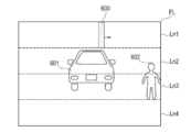
- FIG. 6 is an explanatory view for explaining an object detection principle, and shows a state in which the inside of the measurement space of the light scanning device 10 is scanned with the laser spot light 600 which is emitted according to the rotation of the polygon mirror 53.
- divergent light intermittently emitted in a pulse form from the semiconductor laser 51 is converted into parallel light by the collimator lens 52, and is incident on the first mirror surface M 1 of the rotating polygon mirror 53. Thereafter, the light is reflected by the first mirror surface M1 and further reflected by the second mirror surface M2, and then transmitted through the transparent plate 58 toward the external measurement space, for example, as shown in FIG.
- the laser spot light 600 (shown by hatching) is scanned and projected.
- the direction in which the emitted laser spot light 600 is reflected by the objects 601 and 602 and returns as the reflected light is referred to as a light transmission / reception direction.
- the laser spot light traveling in the same light emitting and receiving direction is detected by the same pixel.
- an object 601 is a vehicle
- an object 602 is a person. Of course, buildings and structures other than these are also detected as objects.
- each mirror surface of the polygon mirror 53 has a different inclination angle with respect to the polygon mirror rotation axis 530.
- the laser light reflected by the first mirror surface M1 and the second mirror surface M2 of the first pair is horizontally from the left to the right in the region Ln1 of the measurement space according to the rotation of the polygon mirror 53. Is scanned (state of FIG. 6).
- the laser light reflected by the second mirror surface M3 and the fourth mirror surface M4 in the second pair is horizontal from the left in the second region Ln2 from the top of the measurement space according to the rotation of the polygon mirror 53. It is scanned to the right.
- the laser light reflected by the fifth mirror surface M5 of the third pair and the sixth mirror surface M6 horizontally moves the first region Ln3 from the top of the measurement space from the left It is scanned to the right.
- the laser light reflected by the seventh mirror surface M7 and the eighth mirror surface M8 of the fourth pair moves from the left to the right in the lowermost region Ln4 of the measurement space according to the rotation of the polygon mirror 53. Is scanned.
- the control unit 12 obtains distance information according to the time difference between the light emission timing of the semiconductor laser 51 and the light reception timing of the photodiode 55.
- the distance image may be transmitted to a remote monitor via a network (not shown) or the like and displayed, or may be stored in the non-volatile memory 124. Also, the obtained distance image may be stored as background image data for object detection by the background subtraction method.
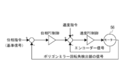
- FIG. 7 is a logic block diagram for explaining the rotational speed control of motor 56.
- FIG. 8 is a timing chart of phase PI (proportional-integral) control.
- the rotation control of the motor 56 is performed by comparing the motor rotation speed which can be calculated by a signal from the motor encoder 61 (indicated as an encoder signal in the drawing) with the speed command to perform speed PI control.
- the signal of the polygon mirror rotation angle detection unit 71 is compared with the phase command (reference signal) generated by the control unit 12 according to the speed command to perform phase PI control. This can improve rotational stability even at low speeds.
- the polygon mirror 53 uses a resin material made of polycarbonate or the like, and the inside is hollow. Such polygon mirror 53 is suitable for weight reduction. However, sudden vibration is likely to cause axial shake and torsional deformation. The rotation speed of the polygon mirror 53 changes when axial deviation or torsional deformation occurs, and an error occurs in the scanning angle when scanning the laser light into the measurement space.
- a pulse-like laser is generated using pulse signals from the motor encoder 61 and the polygon mirror rotation angle detection unit 71 in order to immediately correct (in real time) such an error in the scanning angle caused by the vibration.
- the control of the light emission timing of the laser light is different between when light emission is started on each mirror surface and while the laser light is reflected on the mirror surface and scanned after the start of pulse light emission (hereinafter referred to as after pulse light emission start).
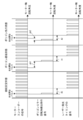
- FIG. 9 is a timing chart for explaining a control method of light emission timing at the start of light emission on each mirror surface.
- the horizontal axis represents the rotation angle of the motor shaft, and the signal of the motor encoder 61, the signal of the polygon mirror rotation angle detection unit 71, and the signal of the laser light emission timing are shown.
- the signal of laser light emission timing is output from the control unit 12 to the semiconductor laser 51, and the semiconductor laser 51 is turned on / off in accordance with this timing signal.
- FIG. 9 shows three states of the rotation stable state, the polygon delay state, and the polygon leading state.
- the illustrated light emission start pulse is a pulse indicating the light emission start time point on each mirror surface M.
- the light emission start pulse is a pulse at a position obtained by counting a predetermined number of pulses for each mirror surface M from a pulse (for example, a pulse whose pulse width is wider than other pulses) indicating the rotation angle reference output by the motor encoder 61 It is.
- the predetermined number of pulses is stored in advance in the control unit 12 and used.
- 5536 pulses which is the resolution of the motor encoder 61, are divided into four and designated for each mirror pair.
- the light emission start pulse for the pair of mirror surfaces M1 and M2 is the first pulse
- the light emission start pulse for the mirror surfaces M3 and M4 is the 1385th pulse
- the light emission start pulse for the mirror surfaces M5 and M6 is The 2769th pulse
- the light emission start pulse for the mirror surfaces M7 and M8 is the 4153th pulse.
- the end of the laser light emission for each mirror surface M is ended when, for example, the pulsed laser light is emitted until it reaches a predetermined number of times (923 pulses in the above example).
- the number of such pulses is merely an example, and is determined according to the size of the mirror surface, the scanning resolution, etc., and the present invention is not limited to the use of these numbers of pulses.
- the control unit 12 receives the pulse of the polygon mirror rotation angle detection unit 71 simultaneously with the reception of the light emission start pulse. Then, upon reception of the pulse of the polygon mirror rotation angle detection unit 71, counting of the pulse of the motor encoder 61 is started to count the second pulse and light emission is started at the same time. Thereafter, the control unit 12 synchronizes with the pulse of the motor encoder 61 to emit light. In this rotation stable state, the rotation angle A0 from the detection of the pulse of the polygon mirror rotation angle detection unit 71 to the emission of the laser beam is not corrected (there is no rotation phase difference).
- the pulse of the polygon mirror rotation angle detection unit 71 is delayed by the rotation phase difference ph1 with respect to the light emission start pulse of the motor encoder 61.
- the control unit 12 receives the pulse of the polygon mirror rotation angle detection unit 71, and detects the difference as the rotation phase difference ph1. Then, after the control unit 12 receives the pulse from the polygon mirror rotation angle detection unit 71, it starts counting the pulse of the motor encoder 61 to count the second pulse and simultaneously to start light emission. After that, the control unit 12 synchronizes the laser light with the pulse of the motor encoder 61 to emit light. In this case, after the pulse of the polygon mirror rotation angle detection unit 71 is detected, the rotation angle up to the laser light emission becomes A1, and the rotation phase difference ph1 is corrected.
- the pulse of the polygon mirror rotation angle detection unit 71 is ahead of the light emission start pulse of the motor encoder 61 by the rotation phase difference ph2.
- the control unit 12 rotates the polygon mirror before detecting the rotation start pulse of the motor encoder 61 in a state where the laser light is not emitted (or while it corresponds to the mirror surface joint in the rotation direction).
- the pulse of the angle detection unit 71 is received.
- a rotation start pulse of the motor encoder 61 is received. That is, before detecting the rotation start pulse of the motor encoder 61, the mirror surface is rotated in advance to the scanning start position. The difference between these pulses is the rotational phase difference ph2.
- the control unit 12 After receiving the pulse of the polygon mirror rotation angle detection unit 71, the control unit 12 starts counting the pulse of the motor encoder 61, counts the second pulse, and simultaneously starts light emission. Let Thereafter, the control unit 12 synchronizes with the pulse of the motor encoder 61 to emit light. As a result, the rotation angle from the detection of the pulse of the polygon mirror rotation angle detection unit 71 to the laser light emission becomes A2, and the correction according to the rotation phase difference ph2 is performed.
- the light emission timing of the laser light detects the polygon mirror rotation angle even if the rotation of the polygon mirror 53 is delayed with respect to the rotation of the motor 56 or precedes After the pulse of the unit 71 is received, counting of the pulse of the motor encoder 61 is started, and the second pulse is counted to emit light at the same time.
- the amount can be corrected to start emission of laser light. Therefore, it is possible to correct in real time the error of the scanning angle of the laser beam caused by the vibration.
- the timing at which the laser light emission start of each mirror surface M can be corrected by the same control.
- the first light emission after the pulse from the polygon mirror rotation angle detection unit 71 is detected is counted by the pulse from the motor encoder 61, and the second pulse is counted simultaneously (this two pulses).
- the period to count be a predetermined period). This is to ensure that the first light emission can be corrected after a period of time when one mirror surface moves to the next mirror surface.
- the predetermined period is not limited to two pulses, and may be a timing that can be corrected in a period in which one mirror surface moves to the next mirror surface, and after the pulse from the polygon mirror rotation angle detection unit 71 is detected.
- the pulse may be synchronized from the pulse of the motor encoder 61 detected first, or may be synchronized after counting two or more pulses. However, since the start of scanning by the next mirror surface will be delayed if the predetermined period is too long, such delay is set so as not to occur.
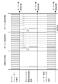
- FIG. 10 is a timing chart for explaining a control method of light emission timing after the start of pulse light emission.
- the horizontal axis represents the rotation angle of the motor shaft, and the signal of the motor encoder 61, the signal of the polygon mirror rotation angle detection unit 71, and the signal of the laser light emission timing are shown.
- three states of the rotation stable state, the polygon delay state A, and the polygon delay state B at another timing are shown.
- the polygon mirror rotation angle detection unit 71 is detected even when the rotation of the polygon mirror 53 precedes the rotation of the motor 56 (polygon lead state).
- the pulse will be received after the pulse of motor encoder 61 previously detected. Therefore, it is not necessary to consider the polygon leading state, and when the control unit 12 receives the pulse of the polygon mirror rotation angle detection unit 71 after receiving the pulse of the motor encoder 61, the received pulse of the motor encoder 61 and the polygon mirror
- the angular difference of the pulses of the rotation angle detection unit 71 is referred to as a rotational phase difference.
- the control of the light emission timing after the start of the pulse light emission is basically the same in both the rotation stable state and the polygon delay states A and B. That is, the control unit 12 emits the laser at the same time as receiving the pulse of the polygon mirror rotation angle detection unit 71. At this time, if the rotational phase difference is detected, it is stored in the control unit 12. Thereafter, while synchronizing with each pulse of the motor encoder 61, light emission is delayed from each pulse by the rotational phase difference.
- the detected rotational phase difference is stored as time in the RAM 122 or the like in the control unit 12 The time is counted by the internal clock (clock for computer operation) of the control unit 12 and delayed.
- the control unit 12 prohibits light emission.
- the safety standard is determined by IEC 60825-1 and JIS C6802 (domestic standard, according to IEC 60825-1) as a standard that classifies the emission level of laser products in consideration of the effects on the human body (eye and skin). ing.
- IEC 60825-1 and JIS C6802 domestic standard, according to IEC 60825-1
- allowable energy within a reference time is defined, and when there are multiple pulses within a certain time, they are calculated together as one pulse. Therefore, when a plurality of pulses emit light continuously at an extremely short time interval, it is necessary to reduce the energy of one pulse or to increase the light emission interval of the pulses.
- the present embodiment in the case where the energy becomes such that the safety standard is not satisfied by the continuous light emission, the light emission interval of the laser is opened. To this end, the present embodiment prohibits laser light emission when the light emission time interval is equal to or less than a predetermined predetermined interval. As described above, the predetermined time is determined to be the laser intensity that meets the safety standard.
- the controller 12 synchronizes with each pulse of the motor encoder 61 after emission prohibited in the polygon delay state B (that is, simultaneously with detection of a pulse of the polygon mirror rotation angle detector 71). The light is emitted with the rotational phase difference ph 4 delayed from each pulse.
- the light emission interval of the pulse can be made equal to or less than the safety standard that does not damage the human body.
- the rotation control of the motor 56 is controlled by the signal of the polygon mirror rotation angle detection unit 71 that detects the rotation angle of the motor encoder 61 and the polygon mirror 53.
- the controllability of the motor 56 is good without being affected by the shaft shake or torsional deformation of the polygon mirror 53.
- the polygon mirror rotation angle detection unit 71 is disposed on the polygon mirror 53, when an axial shake or torsional deformation of the polygon mirror 53 occurs, the change thereof can be detected with certainty.
- control unit 12 controls the light emission timing of the laser light according to the rotational phase difference between the motor 56 and the polygon mirror 53 obtained from the signals of the motor encoder 61 and the polygon mirror rotation angle detection unit 71. For this reason, it is possible to immediately (in real time) correct the error of the scanning angle caused by this rotational phase difference.
- the laser beam can be safely scanned and projected to the measurement space.
- the optical scanning device 10 of the present embodiment is suitable, for example, for a laser radar that measures in three dimensions the distance to an object (object) present in the measurement space.
- Laser radar is also referred to as LiDER (Light Detection and Ranging or Laser Imaging Detection and Ranging).
- the control program of the optical scanning device can also be realized by a dedicated hardware circuit.
- this control program is provided by a computer readable recording medium such as a USB (Universal Serial Bus) memory or a DVD (Digital Versatile Disc) -ROM (Read Only Memory), or the recording medium is not dependent on the Internet etc. It is also possible to provide online via a network.
- the control program is usually stored in a magnetic disk drive or the like that constitutes a storage unit.
- this control program can be provided as a single application software, or can be provided as one function by being incorporated into another software.
- 10 light scanning devices 11 emitting and receiving units, 12 controls, 51 semiconductor lasers, 53 polygon mirrors, 55 photodiodes, 56 motor, 56a motor shaft, 61 motor encoder, 71 polygon mirror rotation angle detection unit, 72 pins, 73 photo interrupters, 75 ring members, 120 buses, 530 Polygon mirror rotation axis.
Landscapes
- Physics & Mathematics (AREA)
- Engineering & Computer Science (AREA)
- General Physics & Mathematics (AREA)
- Computer Networks & Wireless Communication (AREA)
- Radar, Positioning & Navigation (AREA)
- Remote Sensing (AREA)
- Optics & Photonics (AREA)
- Mechanical Optical Scanning Systems (AREA)
- Optical Radar Systems And Details Thereof (AREA)
- Facsimile Scanning Arrangements (AREA)
Abstract
La présente invention concerne un dispositif de balayage optique permettant, même lorsqu'une erreur s'est produite dans un angle de balayage d'un miroir polygonal en raison de l'application d'une vibration, de réparer l'erreur immédiatement. La présente invention concerne un dispositif de balayage optique (10) comprenant : un laser à semi-conducteur (51) permettant d'émettre une lumière laser pulsée ; un miroir polygonal (53) possédant une surface de miroir afin de réfléchir la lumière laser permettant un balayage dans un espace de mesure ; une photodiode (55) permettant de recevoir la lumière réfléchie par un objet dans l'espace de mesure ; un moteur (56) permettant de faire tourner le miroir polygonal (53) ; un codeur de moteur (61) permettant de détecter un angle de rotation du moteur (56) ; une unité de détection d'angle de rotation de miroir polygonal (71) permettant de détecter un angle de rotation du miroir polygonal (53) ; et une unité de commande (12) permettant de commander une synchronisation d'émission de la lumière laser en fonction d'une différence de phase de rotation entre le moteur (56) et le miroir polygonal (53) obtenue à partir de signaux provenant du codeur de moteur (61) et de l'unité de détection d'angle de rotation de miroir polygonal (71).
Priority Applications (1)
| Application Number | Priority Date | Filing Date | Title |
|---|---|---|---|
| JP2019560036A JP7078061B2 (ja) | 2017-12-22 | 2018-08-28 | 光走査装置、光走査装置の制御方法、および光走査装置の制御プログラム |
Applications Claiming Priority (2)
| Application Number | Priority Date | Filing Date | Title |
|---|---|---|---|
| JP2017246651 | 2017-12-22 | ||
| JP2017-246651 | 2017-12-22 |
Publications (1)
| Publication Number | Publication Date |
|---|---|
| WO2019123722A1 true WO2019123722A1 (fr) | 2019-06-27 |
Family
ID=66994553
Family Applications (1)
| Application Number | Title | Priority Date | Filing Date |
|---|---|---|---|
| PCT/JP2018/031799 Ceased WO2019123722A1 (fr) | 2017-12-22 | 2018-08-28 | Dispositif de balayage optique, procédé de commande de dispositif de balayage optique et programme de commande de dispositif de balayage optique |
Country Status (2)
| Country | Link |
|---|---|
| JP (1) | JP7078061B2 (fr) |
| WO (1) | WO2019123722A1 (fr) |
Cited By (5)
| Publication number | Priority date | Publication date | Assignee | Title |
|---|---|---|---|---|
| CN111352236A (zh) * | 2020-04-13 | 2020-06-30 | 陕西伟景机器人科技有限公司 | 一种激光扫描装置 |
| WO2021045003A1 (fr) * | 2019-09-04 | 2021-03-11 | 株式会社デンソー | Dispositif de mesure de distance optique |
| JP2021043190A (ja) * | 2019-09-04 | 2021-03-18 | 株式会社デンソー | 光測距装置 |
| WO2021153304A1 (fr) * | 2020-01-31 | 2021-08-05 | Denso Corporation | Dispositif lidar et procédé de calcul de distance à un objet |
| CN113933813A (zh) * | 2021-09-07 | 2022-01-14 | 陈泽雄 | 一种混合固态激光雷达及其扫描方法 |
Families Citing this family (1)
| Publication number | Priority date | Publication date | Assignee | Title |
|---|---|---|---|---|
| CN116908867A (zh) * | 2023-06-09 | 2023-10-20 | 清华大学 | 基于螺旋相位空间滤波的旋转体探测的装置、方法及存储介质 |
Citations (10)
| Publication number | Priority date | Publication date | Assignee | Title |
|---|---|---|---|---|
| JPH1184006A (ja) * | 1997-07-18 | 1999-03-26 | Denso Corp | 車載レーダ装置 |
| JP2003295311A (ja) * | 2002-04-01 | 2003-10-15 | Matsushita Electric Ind Co Ltd | カラー画像表示装置 |
| JP2011085577A (ja) * | 2009-09-18 | 2011-04-28 | Denso Wave Inc | レーザレーダ装置 |
| JP2014109686A (ja) * | 2012-12-03 | 2014-06-12 | Hokuyo Automatic Co | 偏向装置、光走査装置及び走査式測距装置 |
| US20150323350A1 (en) * | 2014-05-12 | 2015-11-12 | Faro Technologies, Inc. | Robust index correction of an angular encoder based on read head runout |
| JP2016070974A (ja) * | 2014-09-26 | 2016-05-09 | 株式会社デンソー | レーザ照射制御装置 |
| WO2017010197A1 (fr) * | 2015-07-14 | 2017-01-19 | コニカミノルタ株式会社 | Dispositif de moulage, produit moulé, unité miroir et procédé de moulage |
| JP2017054020A (ja) * | 2015-09-10 | 2017-03-16 | キヤノン株式会社 | 光走査装置 |
| JP2017062398A (ja) * | 2015-09-25 | 2017-03-30 | 株式会社豊田中央研究所 | 回転角検出装置及びレーザレーダ装置 |
| JP2017227569A (ja) * | 2016-06-23 | 2017-12-28 | オプテックス株式会社 | レーザースキャンセンサ |
-
2018
- 2018-08-28 JP JP2019560036A patent/JP7078061B2/ja active Active
- 2018-08-28 WO PCT/JP2018/031799 patent/WO2019123722A1/fr not_active Ceased
Patent Citations (10)
| Publication number | Priority date | Publication date | Assignee | Title |
|---|---|---|---|---|
| JPH1184006A (ja) * | 1997-07-18 | 1999-03-26 | Denso Corp | 車載レーダ装置 |
| JP2003295311A (ja) * | 2002-04-01 | 2003-10-15 | Matsushita Electric Ind Co Ltd | カラー画像表示装置 |
| JP2011085577A (ja) * | 2009-09-18 | 2011-04-28 | Denso Wave Inc | レーザレーダ装置 |
| JP2014109686A (ja) * | 2012-12-03 | 2014-06-12 | Hokuyo Automatic Co | 偏向装置、光走査装置及び走査式測距装置 |
| US20150323350A1 (en) * | 2014-05-12 | 2015-11-12 | Faro Technologies, Inc. | Robust index correction of an angular encoder based on read head runout |
| JP2016070974A (ja) * | 2014-09-26 | 2016-05-09 | 株式会社デンソー | レーザ照射制御装置 |
| WO2017010197A1 (fr) * | 2015-07-14 | 2017-01-19 | コニカミノルタ株式会社 | Dispositif de moulage, produit moulé, unité miroir et procédé de moulage |
| JP2017054020A (ja) * | 2015-09-10 | 2017-03-16 | キヤノン株式会社 | 光走査装置 |
| JP2017062398A (ja) * | 2015-09-25 | 2017-03-30 | 株式会社豊田中央研究所 | 回転角検出装置及びレーザレーダ装置 |
| JP2017227569A (ja) * | 2016-06-23 | 2017-12-28 | オプテックス株式会社 | レーザースキャンセンサ |
Cited By (15)
| Publication number | Priority date | Publication date | Assignee | Title |
|---|---|---|---|---|
| CN114341664A (zh) * | 2019-09-04 | 2022-04-12 | 株式会社电装 | 光测距装置 |
| WO2021045003A1 (fr) * | 2019-09-04 | 2021-03-11 | 株式会社デンソー | Dispositif de mesure de distance optique |
| JP2021043190A (ja) * | 2019-09-04 | 2021-03-18 | 株式会社デンソー | 光測距装置 |
| CN114341664B (zh) * | 2019-09-04 | 2025-02-11 | 株式会社电装 | 光测距装置 |
| JP7563045B2 (ja) | 2019-09-04 | 2024-10-08 | 株式会社デンソー | 光測距装置 |
| CN115038985A (zh) * | 2020-01-31 | 2022-09-09 | 株式会社电装 | 用于计算到对象的距离的lidar装置和方法 |
| JP2023507384A (ja) * | 2020-01-31 | 2023-02-22 | 株式会社デンソー | 物体までの距離を計算するためのlidar装置及び方法 |
| US11668832B2 (en) | 2020-01-31 | 2023-06-06 | Denso Corporation | LIDAR device and method for calculating distance to object |
| US11953604B2 (en) | 2020-01-31 | 2024-04-09 | Denso Corporation | LIDAR device and method for calculating distance to object |
| JP7468661B2 (ja) | 2020-01-31 | 2024-04-16 | 株式会社デンソー | 物体までの距離を計算するためのlidar装置及び方法 |
| CN115038985B (zh) * | 2020-01-31 | 2024-09-27 | 株式会社电装 | 用于计算到对象的距离的lidar装置和方法 |
| WO2021153304A1 (fr) * | 2020-01-31 | 2021-08-05 | Denso Corporation | Dispositif lidar et procédé de calcul de distance à un objet |
| CN111352236A (zh) * | 2020-04-13 | 2020-06-30 | 陕西伟景机器人科技有限公司 | 一种激光扫描装置 |
| CN113933813A (zh) * | 2021-09-07 | 2022-01-14 | 陈泽雄 | 一种混合固态激光雷达及其扫描方法 |
| CN113933813B (zh) * | 2021-09-07 | 2025-06-03 | 陈泽雄 | 一种混合固态激光雷达及其扫描方法 |
Also Published As
| Publication number | Publication date |
|---|---|
| JPWO2019123722A1 (ja) | 2021-01-14 |
| JP7078061B2 (ja) | 2022-05-31 |
Similar Documents
| Publication | Publication Date | Title |
|---|---|---|
| JP7078061B2 (ja) | 光走査装置、光走査装置の制御方法、および光走査装置の制御プログラム | |
| JP6380235B2 (ja) | 走査光学系及び走査装置 | |
| US10545223B2 (en) | Optical scanning object detection device detecting object that invades detection area | |
| JPWO2016056545A1 (ja) | 走査光学系及び投受光装置 | |
| EP3206074B1 (fr) | Système optique de balayage, et dispositif de projection et de réception de lumière | |
| US10012831B2 (en) | Optical monitoring of scan parameters | |
| JP7087633B2 (ja) | ライダー、およびライダーの制御方法 | |
| US10649071B2 (en) | Scanning optical system and radar | |
| JP2017227569A (ja) | レーザースキャンセンサ | |
| CN114930188B (zh) | Lidar遮挡检测方法和系统 | |
| JP2018005183A (ja) | 光走査装置、物体検知装置および距離検知装置 | |
| WO2017135225A1 (fr) | Dispositif de détection d'objet de type à balayage optique | |
| JP7416647B2 (ja) | 測量装置 | |
| EP4141385B1 (fr) | Instrument d'arpentage | |
| JP6676974B2 (ja) | 対象物検出装置 | |
| JP4595618B2 (ja) | 光走査装置及び光走査方法 | |
| WO2016059948A1 (fr) | Dispositif optique de balayage | |
| JP6749191B2 (ja) | スキャナ装置および測量装置 | |
| WO2017126356A1 (fr) | Dispositif de détection d'objet | |
| CN220855345U (zh) | 一种光路结构和混合固态激光雷达 | |
| JP7785576B2 (ja) | LiDAR装置およびLiDAR装置の制御方法 | |
| EP4650711A1 (fr) | Dispositif d'arpentage | |
| JP2026040845A (ja) | 走査光学系、およびレーザーレーダー | |
| JP2023050683A (ja) | 測量装置 | |
| JP2023050684A (ja) | 測量装置 |
Legal Events
| Date | Code | Title | Description |
|---|---|---|---|
| 121 | Ep: the epo has been informed by wipo that ep was designated in this application |
Ref document number: 18891164 Country of ref document: EP Kind code of ref document: A1 |
|
| ENP | Entry into the national phase |
Ref document number: 2019560036 Country of ref document: JP Kind code of ref document: A |
|
| NENP | Non-entry into the national phase |
Ref country code: DE |
|
| 122 | Ep: pct application non-entry in european phase |
Ref document number: 18891164 Country of ref document: EP Kind code of ref document: A1 |