WO2017010484A1 - Engin de construction routière - Google Patents
Engin de construction routière Download PDFInfo
- Publication number
- WO2017010484A1 WO2017010484A1 PCT/JP2016/070579 JP2016070579W WO2017010484A1 WO 2017010484 A1 WO2017010484 A1 WO 2017010484A1 JP 2016070579 W JP2016070579 W JP 2016070579W WO 2017010484 A1 WO2017010484 A1 WO 2017010484A1
- Authority
- WO
- WIPO (PCT)
- Prior art keywords
- pump
- current value
- control device
- brake
- traveling hydraulic
- Prior art date
- Legal status (The legal status is an assumption and is not a legal conclusion. Google has not performed a legal analysis and makes no representation as to the accuracy of the status listed.)
- Ceased
Links
Images

Classifications
-
- F—MECHANICAL ENGINEERING; LIGHTING; HEATING; WEAPONS; BLASTING
- F16—ENGINEERING ELEMENTS AND UNITS; GENERAL MEASURES FOR PRODUCING AND MAINTAINING EFFECTIVE FUNCTIONING OF MACHINES OR INSTALLATIONS; THERMAL INSULATION IN GENERAL
- F16H—GEARING
- F16H61/00—Control functions within control units of change-speed- or reversing-gearings for conveying rotary motion ; Control of exclusively fluid gearing, friction gearing, gearings with endless flexible members or other particular types of gearing
- F16H61/38—Control of exclusively fluid gearing
- F16H61/40—Control of exclusively fluid gearing hydrostatic
- F16H61/4035—Control of circuit flow
-
- F—MECHANICAL ENGINEERING; LIGHTING; HEATING; WEAPONS; BLASTING
- F16—ENGINEERING ELEMENTS AND UNITS; GENERAL MEASURES FOR PRODUCING AND MAINTAINING EFFECTIVE FUNCTIONING OF MACHINES OR INSTALLATIONS; THERMAL INSULATION IN GENERAL
- F16H—GEARING
- F16H61/00—Control functions within control units of change-speed- or reversing-gearings for conveying rotary motion ; Control of exclusively fluid gearing, friction gearing, gearings with endless flexible members or other particular types of gearing
- F16H61/38—Control of exclusively fluid gearing
- F16H61/40—Control of exclusively fluid gearing hydrostatic
- F16H61/4008—Control of circuit pressure
-
- E—FIXED CONSTRUCTIONS
- E01—CONSTRUCTION OF ROADS, RAILWAYS, OR BRIDGES
- E01C—CONSTRUCTION OF, OR SURFACES FOR, ROADS, SPORTS GROUNDS, OR THE LIKE; MACHINES OR AUXILIARY TOOLS FOR CONSTRUCTION OR REPAIR
- E01C19/00—Machines, tools or auxiliary devices for preparing or distributing paving materials, for working the placed materials, or for forming, consolidating, or finishing the paving
- E01C19/48—Machines, tools or auxiliary devices for preparing or distributing paving materials, for working the placed materials, or for forming, consolidating, or finishing the paving for laying-down the materials and consolidating them, or finishing the surface, e.g. slip forms therefor, forming kerbs or gutters in a continuous operation in situ
-
- F—MECHANICAL ENGINEERING; LIGHTING; HEATING; WEAPONS; BLASTING
- F16—ENGINEERING ELEMENTS AND UNITS; GENERAL MEASURES FOR PRODUCING AND MAINTAINING EFFECTIVE FUNCTIONING OF MACHINES OR INSTALLATIONS; THERMAL INSULATION IN GENERAL
- F16H—GEARING
- F16H61/00—Control functions within control units of change-speed- or reversing-gearings for conveying rotary motion ; Control of exclusively fluid gearing, friction gearing, gearings with endless flexible members or other particular types of gearing
- F16H61/38—Control of exclusively fluid gearing
- F16H61/40—Control of exclusively fluid gearing hydrostatic
- F16H61/42—Control of exclusively fluid gearing hydrostatic involving adjustment of a pump or motor with adjustable output or capacity
- F16H61/431—Pump capacity control by electro-hydraulic control means, e.g. using solenoid valves
-
- F—MECHANICAL ENGINEERING; LIGHTING; HEATING; WEAPONS; BLASTING
- F16—ENGINEERING ELEMENTS AND UNITS; GENERAL MEASURES FOR PRODUCING AND MAINTAINING EFFECTIVE FUNCTIONING OF MACHINES OR INSTALLATIONS; THERMAL INSULATION IN GENERAL
- F16H—GEARING
- F16H61/00—Control functions within control units of change-speed- or reversing-gearings for conveying rotary motion ; Control of exclusively fluid gearing, friction gearing, gearings with endless flexible members or other particular types of gearing
- F16H61/38—Control of exclusively fluid gearing
- F16H61/40—Control of exclusively fluid gearing hydrostatic
- F16H61/44—Control of exclusively fluid gearing hydrostatic with more than one pump or motor in operation
-
- F—MECHANICAL ENGINEERING; LIGHTING; HEATING; WEAPONS; BLASTING
- F16—ENGINEERING ELEMENTS AND UNITS; GENERAL MEASURES FOR PRODUCING AND MAINTAINING EFFECTIVE FUNCTIONING OF MACHINES OR INSTALLATIONS; THERMAL INSULATION IN GENERAL
- F16H—GEARING
- F16H2312/00—Driving activities
- F16H2312/04—Holding or hillholding
-
- F—MECHANICAL ENGINEERING; LIGHTING; HEATING; WEAPONS; BLASTING
- F16—ENGINEERING ELEMENTS AND UNITS; GENERAL MEASURES FOR PRODUCING AND MAINTAINING EFFECTIVE FUNCTIONING OF MACHINES OR INSTALLATIONS; THERMAL INSULATION IN GENERAL
- F16H—GEARING
- F16H61/00—Control functions within control units of change-speed- or reversing-gearings for conveying rotary motion ; Control of exclusively fluid gearing, friction gearing, gearings with endless flexible members or other particular types of gearing
- F16H61/38—Control of exclusively fluid gearing
- F16H61/40—Control of exclusively fluid gearing hydrostatic
- F16H61/42—Control of exclusively fluid gearing hydrostatic involving adjustment of a pump or motor with adjustable output or capacity
- F16H61/435—Pump capacity control by electric actuators
Definitions
- the present invention relates to a road machine including a traveling hydraulic circuit that employs a hydrostatic continuously variable transmission (HST).
- HST hydrostatic continuously variable transmission
- Patent Document 1 An asphalt finisher having a slope reverse running prevention control circuit that prevents reverse running when starting on a steep slope is known (see Patent Document 1).
- This asphalt finisher includes an HST composed of one hydraulic pump and two hydraulic motors, an angle sensor for detecting the inclination in the longitudinal direction of the vehicle body, and a controller.
- traveling wheels are connected to each hydraulic motor via a reduction gear.
- the controller controls the discharge amount of the hydraulic pump via the tilt regulator, controls the absorption amount of the hydraulic motor via another tilt regulator, and sets the reduction ratio of the speed reducer via the electromagnetic direction switching valve. Control.
- the controller determines that the asphalt finisher is located on a steep uphill during traveling traveling other than during construction, the controller increases the absorption amount of the hydraulic motor and increases the reduction ratio of the reduction gear, The discharge rate is gradually increased to gradually increase the traveling wheel rotation speed.
- Patent Document 1 does not mention the longitudinal relationship between the timing of releasing the brake of the traveling wheel and the timing of starting to increase the discharge amount of the hydraulic pump as described above. Therefore, when the brake is released when the discharge amount of the hydraulic pump is small, even if the absorption amount of the hydraulic motor and the reduction ratio of the reduction gear are increased, there is a possibility that reverse running at the time of starting on a slope cannot be prevented. is there.
- a road machine controls a travel switch for starting travel, a hydrostatic continuously variable transmission including a travel hydraulic pump and a travel hydraulic motor, and a discharge amount of the travel hydraulic pump.
- a pump regulator and a control device that controls the pump regulator using a pump command current, and the pump regulator increases the discharge amount of the traveling hydraulic pump as the current value of the pump command current increases,
- the control device increases the current value of the pump command current to a predetermined value smaller than the maximum current value in response to the ON operation of the travel switch.
- the above-mentioned means provides a road machine that more reliably prevents reverse running when starting on a slope.
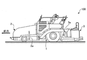
- FIG. 1 is a side view of an asphalt finisher 100 that is an example of a road machine according to an embodiment of the present invention.
- the asphalt finisher 100 mainly includes a tractor 1, a hopper 2, and a screed device 3.
- the tractor 1 is a mechanism for running the asphalt finisher 100.
- the tractor 1 moves the asphalt finisher 100 by rotating the front wheels and the rear wheels using a traveling hydraulic motor.
- the traveling hydraulic motor rotates upon receiving hydraulic oil from a hydraulic source.
- the hopper 2 is a mechanism for receiving pavement material.
- the hopper cylinder 2a is configured to be opened and closed in the vehicle width direction.
- the asphalt finisher 100 normally receives a paving material (for example, asphalt mixture) from the dump truck bed with the hopper 2 fully opened.
- the paving material received in the hopper 2 is fed to the screed device 3 using a conveyor and a screw.
- the screed device 3 is a mechanism for spreading and leveling paving material.
- the screed device 3 is a floating screed device pulled by the tractor 1 and is connected to the tractor 1 via the leveling arm 3a.
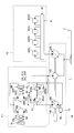
- FIG. 2 is a hydraulic circuit diagram showing a configuration example of a hydraulic system mounted on the asphalt finisher 100 of FIG.
- the hydraulic system mainly includes a hydraulic pressure source 14, a rear wheel drive unit F1, and a conveyor / screw drive unit F2.
- the hydraulic pressure source 14 is a functional element that supplies hydraulic oil for operating various hydraulic drive units including the rear wheel drive unit F1 and the conveyor / screw drive unit F2.
- the hydraulic power source 14 mainly includes an engine 14E, a rear wheel traveling pump 14R, a charge pump 14C, and a conveyor screw pump 14S.
- the engine 14E is a drive source for driving the rear wheel traveling pump 14R, the charge pump 14C, and the conveyor / screw pump 14S.
- the rear wheel traveling pump 14R as a traveling hydraulic pump is a variable displacement hydraulic pump that supplies hydraulic oil for driving to the rear wheel driving unit F1.
- the rear wheel traveling pump 14R is a swash plate type variable displacement bidirectional hydraulic pump used in a closed circuit (HST), and its discharge amount is controlled by the pump regulator 15.
- HST closed circuit
- the discharge amount is a discharge amount per one rotation of the pump, and is also referred to as a displacement volume.
- the pump regulator 15 is a device that controls the discharge amount of the rear wheel traveling pump 14R.
- the pump regulator 15 adjusts the discharge amount of the rear wheel traveling pump 14 ⁇ / b> R according to the pump command current from the controller 30. For example, the larger the current value of the pump command current, the larger the discharge amount of the rear wheel traveling pump 14R.
- the charge pump 14C is a fixed displacement hydraulic pump that supplies hydraulic oil for control to the rear wheel drive unit F1.
- the conveyor / screw pump 14S is a variable displacement hydraulic pump that supplies hydraulic oil to the conveyor / screw drive unit F2.
- the conveyor screw pump 14S is a swash plate type variable displacement hydraulic pump.
- the rear wheel drive unit F1 is a functional element that drives the rear wheels 5L and 5R.
- the rear wheel drive unit F1 includes a left rear wheel traveling motor 20L, a right rear wheel traveling motor 20R, check valves 20La and 20Ra, relief valves 20Lb and 20Rb, reduction ratio control devices 21L and 21R, and a brake.
- Control devices 22L and 22R are included.
- the left rear wheel traveling motor 20L is a hydraulic motor that drives the left rear wheel 5L.
- the right rear wheel traveling motor 20R is a hydraulic motor that drives the right rear wheel 5R.
- the left rear wheel traveling motor 20L and the right rear wheel traveling motor 20R are variable displacement hydraulic motors, and form a closed circuit (HST) together with the rear wheel traveling pump 14R.
- the left rear wheel traveling motor 20L and the right rear wheel traveling motor 20R may be fixed displacement hydraulic motors.
- the check valve 20La determines the pressure of the hydraulic oil in the pipe C1 that connects the first port of the rear wheel traveling pump 14R and the second ports of the left rear wheel traveling motor 20L and the right rear wheel traveling motor 20R. Maintain above predetermined pressure. Specifically, the check valve 20La causes the hydraulic oil discharged from the charge pump 14C to flow into the pipe line C1 when the pressure of the hydraulic oil in the pipe line C1 falls below the discharge pressure of the charge pump 14C.
- the numbers in parentheses in the figure represent port numbers.
- the check valve 20Ra is a hydraulic oil in the pipe line C2 that connects the second port of the rear wheel traveling pump 14R and the first ports of the left rear wheel traveling motor 20L and the right rear wheel traveling motor 20R.
- the pressure is maintained at a predetermined pressure or higher.
- the check valve 20Ra causes the hydraulic oil discharged from the charge pump 14C to flow into the pipe C2 when the pressure of the hydraulic oil in the pipe C2 falls below the discharge pressure of the charge pump 14C.
- the relief valve 20Lb maintains the pressure of the hydraulic oil in the pipe line C1 below a predetermined relief pressure. Specifically, the relief valve 20Lb causes the hydraulic oil in the pipe C1 to flow out of the closed circuit when the pressure of the hydraulic oil in the pipe C1 exceeds the relief pressure. Similarly, the relief valve 20Rb maintains the pressure of the hydraulic oil in the pipe line C2 below a predetermined relief pressure. Specifically, the relief valve 20Rb causes the hydraulic oil in the pipe C2 to flow out of the closed circuit when the pressure of the hydraulic oil in the pipe C2 exceeds the relief pressure.
- the reduction ratio control device 21L is a device that controls the reduction ratio of the reduction gear connected to the left rear wheel travel motor 20L.
- the reduction ratio control device 21L determines the reduction ratio of the reduction gear connected to the left rear wheel travel motor 20L using the hydraulic oil discharged from the charge pump 14C in response to a control command from the controller 30. adjust.
- the brake control device 22L is a device that controls the braking force of the left rear wheel brake that brakes the left rear wheel 5L of the asphalt finisher 100.
- the brake control device 22L adjusts the braking force of the left rear wheel brake using hydraulic oil discharged from the charge pump 14C in response to a control command from the controller 30.
- the conveyor / screw driving unit F2 is a functional element that drives the conveyor and the screw.
- the conveyor screw driving unit F2 mainly includes a left screw motor 42SL, a right screw motor 42SR, a left conveyor motor 42CL, a right conveyor motor 42CR, and a conveyor screw valve 41.
- Each of the left screw motor 42SL, the right screw motor 42SR, the left conveyor motor 42CL, and the right conveyor motor 42CR is a variable displacement hydraulic motor that forms an open circuit.
- the conveyor / screw valve 41 includes a conveyor control valve and a screw control valve.
- the conveyor control valve is switched in response to a control command from the controller 30.
- the hydraulic oil discharged from the conveyor screw pump 14S is caused to flow into at least one suction port of the left conveyor motor 42CL and the right conveyor motor 42CR. Further, the hydraulic oil flowing out from at least one discharge port of the left conveyor motor 42CL and the right conveyor motor 42CR is discharged to the hydraulic oil tank T.
- the screw control valve is switched in response to a control command from the controller 30.
- the hydraulic oil discharged from the conveyor / screw pump 14S is caused to flow into at least one suction port of the left screw motor 42SL and the right screw motor 42SR. Further, the hydraulic oil flowing out from at least one discharge port of the left screw motor 42SL and the right screw motor 42SR is discharged to the hydraulic oil tank T.
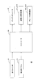
- the traveling control system 50 mainly includes a traveling switch 10, a speed dial 11, a controller 30, a pump regulator 15, reduction ratio control devices 21L and 21R, and brake control devices 22L and 22R.
- the traveling switch 10 is a switch for starting the traveling of the asphalt finisher 100.
- the travel switch 10 is attached to a place where a driver sitting on a driver's seat installed on the tractor 1 can operate.
- the speed dial 11 is a dial for setting the target traveling speed of the asphalt finisher 100.
- the speed dial 11 is attached to a place where the driver sitting on the driver's seat installed in the upper part of the tractor 1 can operate, like the travel switch 10.
- the controller 30 is a control device that controls the asphalt finisher 100.
- the controller 30 is composed of an arithmetic processing unit including a CPU and an internal memory. Various functions of the controller 30 are realized by the CPU executing a program stored in the internal memory.
- the backward movement of the asphalt finisher 100 located on the inclined surface occurs when the forward rotation torque for forward rotation of the rear wheel running motors 20L and 20R is smaller than the reverse rotation torque when the rear wheel brake is released. To do. Further, the forward rotation torque is generated based on the discharge pressure of the rear wheel traveling pump 14R, and the reverse rotation torque is generated based on the own weight of the asphalt finisher 100. Therefore, when the discharge amount of the rear wheel traveling pump 14R is small when the asphalt finisher 100 starts to move, the asphalt finisher 100 is likely to be retracted.
- the controller 30 prevents the asphalt finisher 100 from moving backward by increasing the discharge amount of the rear wheel traveling pump 14R when the asphalt finisher 100 starts to move.
- the asphalt finisher 100 may be suddenly started. Further, when the release of the brake is delayed, the forward rotation torque by the rear wheel traveling pump 14R may act to invalidate the braking torque by the brake, and the brake may be damaged. Accordingly, it is necessary to appropriately determine the increase width of the discharge amount of the rear wheel traveling pump 14R and the brake release timing at the start of movement.
- the controller 30 executes various calculations based on the outputs of the travel switch 10 and the speed dial 11, and sends various control commands based on the calculation results to the pump regulator 15, the reduction ratio control devices 21L and 21R, and the brake. Output to the control devices 22L and 22R.
- the controller 30 acquires the target travel speed Vt set by the speed dial 11 and determines various parameters used for controlling the pump regulator 15.
- the various parameters include a movement start current value Am, a movement start time D1, a current value increase rate ⁇ , a target current value At, and the like.
- the movement start current value Am is a current value when the asphalt finisher 100 starts to move forward when the current value of the pump command current is gradually increased in order to move the asphalt finisher 100 forward. For example, when the asphalt finisher 100 located on the inclined surface is temporarily retracted when moving, this corresponds to the current value when the asphalt finisher 100 returns to the initial position by the subsequent advancement. It may be a current value when the backward movement is stopped.
- the movement start time D1 is a time required from the start of the gradual increase of the current value of the pump command current to advance the asphalt finisher 100 located on the inclined surface until the movement start current value Am is reached.
- the movement start current value Am and the movement start time D1 are values determined according to the slope of the inclined surface, the model of the road machine, etc., and may be stored in advance in an internal memory or the like, or may be input through an input device (not shown). . Alternatively, it may be dynamically calculated based on the output of an angle sensor that detects the inclination of the vehicle body in the longitudinal direction attached to the tractor 1.
- the current value increase rate ⁇ is a value obtained by dividing the movement start current value Am by the movement start time D1, and corresponds to the traveling acceleration of the asphalt finisher 100. That is, the traveling acceleration of the asphalt finisher 100 when starting to move increases as the current value increase rate ⁇ increases.
- the target current value At is a current value of the pump command current corresponding to the target travel speed Vt of the asphalt finisher 100 set by the speed dial 11. Further, the target current value At means the maximum current value that can be adopted as the pump command current unless the setting of the speed dial 11 is changed. Further, the movement start current value Am is smaller than the target current value At as the maximum current value. That is, the maximum current value is a current value corresponding to the maximum horsepower, and the movement start current value Am is a current value corresponding to a horsepower smaller than the maximum horsepower.
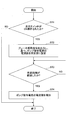
- FIG. 4 is a flowchart illustrating an exemplary flow of the travel control process. During the operation of the asphalt finisher 100, the controller 30 repeatedly executes this travel control process at a predetermined control cycle.
- the controller 30 determines whether or not the travel switch 10 has been turned ON (step ST1).
- step ST1 If it is determined that the travel switch 10 has not been turned ON (NO in step ST1), the controller 30 ends the current travel control process.
- step ST1 When it is determined that the travel switch 10 has been turned ON (YES in step ST1), the controller 30 outputs a brake release command to the brake control devices 22L and 22R and simultaneously outputs a pump command current to the pump regulator 15.
- the current value is set to a predetermined value (movement current value Am) (step ST2).
- controller 30 may start driving the left screw motor 42SL, the right screw motor 42SR, the left conveyor motor 42CL, and the right conveyor motor 42CR in accordance with the ON operation of the travel switch 10.
- the controller 30 determines whether or not a predetermined time (movement start time D1) has elapsed after the ON operation of the travel switch 10 (step ST3).
- step ST3 When it is determined that the movement start time D1 has not elapsed (NO in step ST3), the controller 30 repeats the determination in step ST3 until the movement start time D1 has elapsed.
- the controller 30 increases the current value of the pump command current (step ST4).
- the controller 30 increases the current value of the pump command current to a predetermined maximum current value (target current value At) at a predetermined increase rate (current value increase rate ⁇ ).
- the current value increase rate ⁇ is a value determined by the movement start current value Am and the movement start time D1
- the target current value At is a value determined by the target travel speed Vt set by the speed dial 11.
- FIG. 5 the temporal transition of various physical quantities related to the travel control process will be described.
- Various physical quantities are the output state of the travel switch 10 shown in FIG. 5A, the output state of the brake release command shown in FIG. 5B, the current value of the pump command current shown in FIG. It is a traveling speed of the asphalt finisher 100 shown in (D).
- the continuous line of FIG. 5 shows the time transition when a driving
- the alternate long and short dash line in FIG. 5 indicates a temporal transition when the pump command current gradually increases without executing the traveling control process.
- the output state of the travel switch 10 becomes the ON level. Further, as shown in FIG. 5B, the output state of the brake release command also becomes the ON level.
- the pump command current starts to move at time t0 and increases in a stepped manner up to the current value Am.
- the discharge horsepower of the pump 14R for rear wheel traveling can be rapidly increased to a predetermined value.
- the traveling speed of the asphalt finisher 100 starts to increase at time t1, and reaches the target traveling speed Vt at time t2. That is, the asphalt finisher 100 can move forward and climb a slope without moving backward at the start of movement.
- the traveling control process when the traveling control process is not executed, the pump command current starts to gradually increase at the current value increase rate ⁇ at time t0, for example, as indicated by the one-dot chain line in FIG. Reach Am.
- the traveling speed of the asphalt finisher 100 starts to shift to the minus side (reverse side) at time t0.
- the traveling speed of the asphalt finisher 100 starts to shift to the minus side (reverse side) at time t0.
- the plus side forward side
- the asphalt finisher 100 starts to move forward after it temporarily moves backward at the start of movement.
- the time from time t0 to time t1 corresponds to the time required for the pump command current to start from the value zero and to reach the current value Am (movement start time D1).
- the controller 30 increases the discharge amount of the rear wheel traveling pump 14R at the time of starting movement at an early stage. For this reason, the discharge pressure of the rear wheel traveling pump 14R, and hence the forward rotational torque for causing the rear wheel traveling motors 20L and 20R to forward rotate, is increased early.
- the forward rotation torque is set to be larger than the reverse rotation torque due to the weight of the asphalt finisher 100. As a result, it is possible to prevent the asphalt finisher 100 from retreating when the asphalt finisher 100 located on the uphill starts to advance. Further, the start of running of the asphalt finisher 100 can be smoothed to prevent the quality of the construction surface from deteriorating.
- the increase timing at which the current value of the pump current command starts to move up to the current value Am stepwise and the output timing of the brake release command are simultaneously set.
- the output timing of the brake release command may be set later than the increase timing of the pump current command. This is because the pressure of the hydraulic fluid on the suction side of the rear wheel running motors 20L and 20R is more reliably set to a predetermined pressure or higher before the brake is completely released. That is, before the brake is completely released, the forward rotation torque by the rear wheel traveling pump 14R is more reliably increased than the reverse rotation torque. There is a time lag between the output timing of the brake release command and the timing at which braking by the brake is actually completely released.
- the longitudinal relationship between the increase timing of the pump current command and the output timing of the brake release command may be determined in consideration of this temporal shift. For example, when the time shift is large, the output timing of the brake release command may be set earlier than the increase timing of the pump current command.
- FIG. 5C shows a control example in the case of using the pump regulator 15 having a structure in which the discharge amount of the rear wheel traveling pump 14R is increased as the current value of the pump command current is increased.
- the present invention is not limited to this configuration.
- a pump regulator having a structure in which the discharge amount of the rear wheel traveling pump 14R is increased as the current value of the pump command current is smaller may be used.
- the controller 30 increases the pump command current toward the maximum current value corresponding to the minimum horsepower when it is desired to reduce the discharge amount, and toward the minimum current value corresponding to the maximum horsepower when it is desired to increase the discharge amount. Reduce pump command current.
- the controller 30 starts to reduce the current value of the pump command current to a current value Am (a predetermined value greater than the minimum current value) in a stepwise manner. That is, the minimum current value is a current value corresponding to the maximum horsepower, and the movement start current value Am is a current value corresponding to a horsepower smaller than the maximum horsepower.
Landscapes
- Engineering & Computer Science (AREA)
- General Engineering & Computer Science (AREA)
- Mechanical Engineering (AREA)
- Architecture (AREA)
- Civil Engineering (AREA)
- Structural Engineering (AREA)
- Control Of Fluid Gearings (AREA)
- Road Paving Machines (AREA)
- Transportation (AREA)
- Regulating Braking Force (AREA)
- Chemical & Material Sciences (AREA)
- Combustion & Propulsion (AREA)
- Automation & Control Theory (AREA)
Abstract
Selon un mode de réalisation, cette invention concerne un dispositif de finition d'asphaltage (100), comprenant : un commutateur d'entraînement (10) pour initier l'entraînement ; une transmission hydrostatique à variation continue comprenant une pompe d'entraînement de roue arrière (14R) et des moteurs d'entraînement de roue arrière (20L, 20R) ; un régulateur de pompe (15) pour commander le volume de refoulement de la pompe d'entraînement (14R) ; et un contrôleur (30) pour commander le régulateur de pompe (15) en utilisant un courant de commande de pompe. Le régulateur de pompe (15) augmente le volume de refoulement de la pompe d'entraînement des roues arrière (14R) à mesure que la valeur de courant du courant de commande de pompe augmente, et le contrôleur (30) augmente la valeur de courant du courant de commande de pompe à une valeur prescrite qui est inférieure à une valeur de courant maximale en réponse à la mise sous tension de l'interrupteur d'entraînement (10).
Priority Applications (4)
| Application Number | Priority Date | Filing Date | Title |
|---|---|---|---|
| EP16824464.8A EP3323938B1 (fr) | 2015-07-13 | 2016-07-12 | Engin de construction routière |
| JP2017528689A JP6648136B2 (ja) | 2015-07-13 | 2016-07-12 | アスファルトフィニッシャ |
| CN201680041255.XA CN107835880B (zh) | 2015-07-13 | 2016-07-12 | 道路机械 |
| US15/868,137 US10962110B2 (en) | 2015-07-13 | 2018-01-11 | Road machine |
Applications Claiming Priority (2)
| Application Number | Priority Date | Filing Date | Title |
|---|---|---|---|
| JP2015-139989 | 2015-07-13 | ||
| JP2015139989 | 2015-07-13 |
Related Child Applications (1)
| Application Number | Title | Priority Date | Filing Date |
|---|---|---|---|
| US15/868,137 Continuation US10962110B2 (en) | 2015-07-13 | 2018-01-11 | Road machine |
Publications (1)
| Publication Number | Publication Date |
|---|---|
| WO2017010484A1 true WO2017010484A1 (fr) | 2017-01-19 |
Family
ID=57757452
Family Applications (1)
| Application Number | Title | Priority Date | Filing Date |
|---|---|---|---|
| PCT/JP2016/070579 Ceased WO2017010484A1 (fr) | 2015-07-13 | 2016-07-12 | Engin de construction routière |
Country Status (5)
| Country | Link |
|---|---|
| US (1) | US10962110B2 (fr) |
| EP (1) | EP3323938B1 (fr) |
| JP (1) | JP6648136B2 (fr) |
| CN (1) | CN107835880B (fr) |
| WO (1) | WO2017010484A1 (fr) |
Families Citing this family (3)
| Publication number | Priority date | Publication date | Assignee | Title |
|---|---|---|---|---|
| IT202000023830A1 (it) * | 2020-10-09 | 2022-04-09 | Cnh Ind Italia Spa | Metodo e sistema di controllo di una trasmissione idraulica di una macchina da lavoro o agricola |
| JP2024130173A (ja) * | 2023-03-14 | 2024-09-30 | 株式会社クボタ | 作業車両 |
| DE102024124568A1 (de) * | 2024-08-28 | 2026-03-05 | Bomag Gmbh | Baumaschine, insbesondere eine tandemwalze, sowie ein verfahren zum umrüsten einer baumaschine |
Citations (7)
| Publication number | Priority date | Publication date | Assignee | Title |
|---|---|---|---|---|
| JPH093820A (ja) * | 1995-06-16 | 1997-01-07 | Sakai Heavy Ind Ltd | 舗装車両 |
| JP2002039374A (ja) | 2000-07-26 | 2002-02-06 | Sumitomo (Shi) Construction Machinery Manufacturing Co Ltd | アスファルトフィニッシャの坂道逆走防止制御回路及びその制御方法 |
| JP2005147275A (ja) * | 2003-11-17 | 2005-06-09 | Sumitomo (Shi) Construction Machinery Manufacturing Co Ltd | 舗装機械の走行駆動制御装置 |
| JP2006009272A (ja) * | 2004-06-22 | 2006-01-12 | Sumitomo (Shi) Construction Machinery Manufacturing Co Ltd | 車輪走行型アスファルトフィニシャの走行駆動装置 |
| JP2009083783A (ja) * | 2007-10-02 | 2009-04-23 | Yanmar Co Ltd | 作業車両の変速装置 |
| JP2013023811A (ja) * | 2011-07-14 | 2013-02-04 | Sumitomo (Shi) Construction Machinery Co Ltd | 建設機械 |
| JP2015139989A (ja) | 2014-01-30 | 2015-08-03 | 京セラドキュメントソリューションズ株式会社 | 画像形成装置及び災害時支援システム |
Family Cites Families (22)
| Publication number | Priority date | Publication date | Assignee | Title |
|---|---|---|---|---|
| US5489007A (en) * | 1994-07-15 | 1996-02-06 | Caterpillar Inc. | Dynamic braking on an all wheel drive machine |
| JP3635927B2 (ja) * | 1998-06-19 | 2005-04-06 | 株式会社デンソー | 車両におけるエンジン自動停止・始動装置 |
| DE10303206A1 (de) * | 2003-01-28 | 2004-07-29 | Zf Friedrichshafen Ag | Hydrostatisches Getriebe |
| JP4446822B2 (ja) * | 2004-07-13 | 2010-04-07 | 日立建機株式会社 | 作業車両の油圧駆動装置 |
| US7757486B2 (en) * | 2004-09-27 | 2010-07-20 | Hitachi Construction Machinery Co., Ltd. | Engine control device for work vehicle |
| JP4489697B2 (ja) * | 2005-12-27 | 2010-06-23 | 住友建機株式会社 | 建設機械のエンジン制御装置 |
| JP4704938B2 (ja) * | 2006-03-13 | 2011-06-22 | 株式会社クボタ | 作業車 |
| FR2911658B1 (fr) * | 2007-01-22 | 2009-04-24 | Poclain Hydraulics Ind Soc Par | Dispositif de transmission hydrostatique d'un engin. |
| JP5156237B2 (ja) * | 2007-01-24 | 2013-03-06 | 株式会社小松製作所 | 油圧駆動装置及び油圧駆動車両 |
| WO2008123376A1 (fr) * | 2007-03-30 | 2008-10-16 | Komatsu Ltd. | Organe de commande de véhicule avec transmission à variation continue hydrostatique |
| JP4640386B2 (ja) * | 2007-07-20 | 2011-03-02 | トヨタ自動車株式会社 | ブレーキ装置およびブレーキ制御方法 |
| DE102010028279A1 (de) * | 2010-04-28 | 2011-11-03 | Continental Teves Ag & Co. Ohg | Verfahren zum Betrieb einer Bremsanlage |
| DE102010020528B4 (de) * | 2010-05-14 | 2023-05-17 | Robert Bosch Gmbh | Hydrostatischer Antrieb |
| JP5332044B2 (ja) * | 2010-09-10 | 2013-11-06 | 株式会社小松製作所 | 作業車両のエンジンオーバーラン防止制御装置 |
| US8924115B2 (en) * | 2010-12-22 | 2014-12-30 | Caterpillar Inc. | System and method for controlling a brake system |
| US8844279B2 (en) * | 2011-05-31 | 2014-09-30 | Caterpillar Inc. | Hydraulic fan circuit |
| CN102251462A (zh) * | 2011-06-09 | 2011-11-23 | 三一重工股份有限公司 | 压路机及其运动控制装置与方法 |
| US9206562B2 (en) * | 2012-03-08 | 2015-12-08 | Caterpillar Paving Products Inc. | Grade propulsion system and method |
| JP5092059B1 (ja) * | 2012-03-29 | 2012-12-05 | 株式会社小松製作所 | 作業車両及び作業車両の制御方法 |
| CN104684783B (zh) * | 2012-07-12 | 2017-08-25 | 凯斯纽荷兰(中国)管理有限公司 | 用于控制工作车辆的回退的系统和方法 |
| DE102013202385A1 (de) * | 2013-02-14 | 2014-08-14 | Zf Friedrichshafen Ag | Verfahren zur Steuerung eines hydrostatischen Getriebes |
| US9120658B2 (en) * | 2013-12-27 | 2015-09-01 | Komatsu Ltd. | Forklift and control method of forklift |
-
2016
- 2016-07-12 WO PCT/JP2016/070579 patent/WO2017010484A1/fr not_active Ceased
- 2016-07-12 JP JP2017528689A patent/JP6648136B2/ja active Active
- 2016-07-12 EP EP16824464.8A patent/EP3323938B1/fr active Active
- 2016-07-12 CN CN201680041255.XA patent/CN107835880B/zh active Active
-
2018
- 2018-01-11 US US15/868,137 patent/US10962110B2/en active Active
Patent Citations (7)
| Publication number | Priority date | Publication date | Assignee | Title |
|---|---|---|---|---|
| JPH093820A (ja) * | 1995-06-16 | 1997-01-07 | Sakai Heavy Ind Ltd | 舗装車両 |
| JP2002039374A (ja) | 2000-07-26 | 2002-02-06 | Sumitomo (Shi) Construction Machinery Manufacturing Co Ltd | アスファルトフィニッシャの坂道逆走防止制御回路及びその制御方法 |
| JP2005147275A (ja) * | 2003-11-17 | 2005-06-09 | Sumitomo (Shi) Construction Machinery Manufacturing Co Ltd | 舗装機械の走行駆動制御装置 |
| JP2006009272A (ja) * | 2004-06-22 | 2006-01-12 | Sumitomo (Shi) Construction Machinery Manufacturing Co Ltd | 車輪走行型アスファルトフィニシャの走行駆動装置 |
| JP2009083783A (ja) * | 2007-10-02 | 2009-04-23 | Yanmar Co Ltd | 作業車両の変速装置 |
| JP2013023811A (ja) * | 2011-07-14 | 2013-02-04 | Sumitomo (Shi) Construction Machinery Co Ltd | 建設機械 |
| JP2015139989A (ja) | 2014-01-30 | 2015-08-03 | 京セラドキュメントソリューションズ株式会社 | 画像形成装置及び災害時支援システム |
Non-Patent Citations (1)
| Title |
|---|
| See also references of EP3323938A4 |
Also Published As
| Publication number | Publication date |
|---|---|
| EP3323938B1 (fr) | 2020-08-26 |
| EP3323938A4 (fr) | 2018-08-15 |
| EP3323938A1 (fr) | 2018-05-23 |
| JPWO2017010484A1 (ja) | 2018-05-10 |
| JP6648136B2 (ja) | 2020-02-14 |
| US20180134297A1 (en) | 2018-05-17 |
| CN107835880B (zh) | 2021-04-30 |
| CN107835880A (zh) | 2018-03-23 |
| US10962110B2 (en) | 2021-03-30 |
Similar Documents
| Publication | Publication Date | Title |
|---|---|---|
| JP5092060B1 (ja) | 作業車両及び作業車両の制御方法 | |
| US8418797B2 (en) | Work vehicle | |
| JP5192601B1 (ja) | 作業車両及び作業車両の制御方法 | |
| JP4990334B2 (ja) | 作業車両 | |
| US9650760B2 (en) | Work vehicle | |
| WO2005033557A1 (fr) | Dispositif de commande de translation pour vehicule a entrainement hydraulique, et vehicule a entrainement hydraulique | |
| CN104024018A (zh) | 具有滑行功能的液压驱动系统 | |
| JP6648136B2 (ja) | アスファルトフィニッシャ | |
| JP2009522147A (ja) | 車両操舵装置および方法 | |
| JP7417485B2 (ja) | 作業機械、および作業機械を制御するための方法 | |
| CN101501368B (zh) | 液压驱动车辆的行驶控制装置 | |
| CN116018451B (zh) | 作业机械 | |
| WO2020100615A1 (fr) | Engin de chantier et procédé de commande d'engin de chantier | |
| JP4069795B2 (ja) | 油圧走行駆動装置 | |
| JP2004116706A (ja) | 油圧駆動車両の走行制御装置および油圧駆動車両 | |
| JP4915927B2 (ja) | コンバイン | |
| JP2012052581A (ja) | 油圧走行駆動装置 | |
| JP5364652B2 (ja) | 走行用hst | |
| JP7348868B2 (ja) | 作業車両の変速装置 | |
| JP2008306972A (ja) | コンバイン | |
| JP4933343B2 (ja) | 作業車の前輪増速機構 | |
| JP2026043871A (ja) | 作業機械および作業機械の制御方法 | |
| JP2000274402A (ja) | 油圧走行式作業車両 |
Legal Events
| Date | Code | Title | Description |
|---|---|---|---|
| 121 | Ep: the epo has been informed by wipo that ep was designated in this application |
Ref document number: 16824464 Country of ref document: EP Kind code of ref document: A1 |
|
| ENP | Entry into the national phase |
Ref document number: 2017528689 Country of ref document: JP Kind code of ref document: A |
|
| NENP | Non-entry into the national phase |
Ref country code: DE |
|
| WWE | Wipo information: entry into national phase |
Ref document number: 2016824464 Country of ref document: EP |