WO2017010508A1 - リボンカセット - Google Patents
リボンカセット Download PDFInfo
- Publication number
- WO2017010508A1 WO2017010508A1 PCT/JP2016/070669 JP2016070669W WO2017010508A1 WO 2017010508 A1 WO2017010508 A1 WO 2017010508A1 JP 2016070669 W JP2016070669 W JP 2016070669W WO 2017010508 A1 WO2017010508 A1 WO 2017010508A1
- Authority
- WO
- WIPO (PCT)
- Prior art keywords
- spool
- ribbon
- ink ribbon
- winding
- cassette
- Prior art date
- Legal status (The legal status is an assumption and is not a legal conclusion. Google has not performed a legal analysis and makes no representation as to the accuracy of the status listed.)
- Ceased
Links
Images


Classifications
-
- B—PERFORMING OPERATIONS; TRANSPORTING
- B41—PRINTING; LINING MACHINES; TYPEWRITERS; STAMPS
- B41J—TYPEWRITERS; SELECTIVE PRINTING MECHANISMS, i.e. MECHANISMS PRINTING OTHERWISE THAN FROM A FORME; CORRECTION OF TYPOGRAPHICAL ERRORS
- B41J32/00—Ink-ribbon cartridges
-
- B—PERFORMING OPERATIONS; TRANSPORTING
- B41—PRINTING; LINING MACHINES; TYPEWRITERS; STAMPS
- B41J—TYPEWRITERS; SELECTIVE PRINTING MECHANISMS, i.e. MECHANISMS PRINTING OTHERWISE THAN FROM A FORME; CORRECTION OF TYPOGRAPHICAL ERRORS
- B41J17/00—Mechanisms for manipulating page-width impression-transfer material, e.g. carbon paper
- B41J17/22—Supply arrangements for webs of impression-transfer material
- B41J17/24—Webs supplied from reels or spools attached to the machine
-
- B—PERFORMING OPERATIONS; TRANSPORTING
- B41—PRINTING; LINING MACHINES; TYPEWRITERS; STAMPS
- B41J—TYPEWRITERS; SELECTIVE PRINTING MECHANISMS, i.e. MECHANISMS PRINTING OTHERWISE THAN FROM A FORME; CORRECTION OF TYPOGRAPHICAL ERRORS
- B41J17/00—Mechanisms for manipulating page-width impression-transfer material, e.g. carbon paper
- B41J17/32—Detachable carriers or holders for impression-transfer material mechanism
-
- B—PERFORMING OPERATIONS; TRANSPORTING
- B41—PRINTING; LINING MACHINES; TYPEWRITERS; STAMPS
- B41J—TYPEWRITERS; SELECTIVE PRINTING MECHANISMS, i.e. MECHANISMS PRINTING OTHERWISE THAN FROM A FORME; CORRECTION OF TYPOGRAPHICAL ERRORS
- B41J2/00—Typewriters or selective printing mechanisms characterised by the printing or marking process for which they are designed
- B41J2/315—Typewriters or selective printing mechanisms characterised by the printing or marking process for which they are designed characterised by selective application of heat to a heat sensitive printing or impression-transfer material
- B41J2/32—Typewriters or selective printing mechanisms characterised by the printing or marking process for which they are designed characterised by selective application of heat to a heat sensitive printing or impression-transfer material using thermal heads
- B41J2/325—Typewriters or selective printing mechanisms characterised by the printing or marking process for which they are designed characterised by selective application of heat to a heat sensitive printing or impression-transfer material using thermal heads by selective transfer of ink from ink carrier, e.g. from ink ribbon or sheet
Definitions
- the present invention relates to a ribbon cassette for storing an ink ribbon.
- the ribbon cassette described in Patent Document 1 includes a ribbon spool and a take-up spool that are rotatably supported by a cassette case.
- An ink ribbon is wound around the ribbon spool.
- the take-up spool draws out the ink ribbon from the ribbon spool and winds up the ink ribbon used for printing characters and the like.
- a clutch spring is provided at the lower end of the take-up spool. The clutch spring applies a rotational load to the take-up spool when an external force that rotates the take-up spool in the direction opposite to the take-up direction of the ink ribbon is applied. Thereby, the state in which an appropriate tension is applied to the ink ribbon is maintained.
- the user may press the ink ribbon to loosen it. In this case, it has been difficult for the conventional ribbon cassette to return the slackened ink ribbon to a state where an appropriate tension is applied.
- An object of the present invention is to provide a ribbon cassette that can return a slackened ink ribbon to a state where an appropriate tension is applied.
- the ribbon cassette according to the first aspect of the present invention includes a box-shaped cassette case, a first hole accommodated in the cassette case and provided in the first outer wall of the cassette case, and a second outer wall of the cassette case.
- An ink ribbon partially exposed from the cassette case between the provided second hole, a cylindrical first spool that is rotatably supported by the cassette case and wound around one end of the ink ribbon;
- a cylindrical second spool that is rotatably supported by the cassette case, the other end of the ink ribbon being connected to the first portion, an engaging portion provided in the cassette case, and the second spool.
- a spring member wound around a second portion different from the first portion wherein the spring member extends from a winding portion wound around the second portion and a first end portion of the winding portion.
- An extending portion that engages with the engaging portion, and the winding portion is relative to a winding direction when the second spool winds the ink ribbon from the first end portion.
- the second pull-out load when the ink ribbon is pulled out from the second spool side through the second hole is wound through the first hole. It is characterized by being smaller than the first drawing load when the ink ribbon is drawn from the first spool side.
- the winding portion extends from the first end where the extending portion extends to the second spool in a direction relatively opposite to the winding direction. It is wound in two parts.
- the winding portion increases in diameter when the second spool rotates in the winding direction, and decreases in diameter when the second spool rotates in the direction opposite to the winding direction.
- the second drawer load is the first drawer load. The second spool rotates in the direction opposite to the winding direction.
- the spring member rotates in the direction opposite to the winding direction as the second spool rotates in the direction opposite to the winding direction.
- the winding portion is reduced in diameter, and the extended portion is elastically deformed with the contact portion with the engaging portion as a fulcrum. That is, the second spool rotates in the direction opposite to the winding direction by the amount of elastic deformation of the extending portion. Therefore, the ink ribbon is pulled out from the second spool by an external force of a predetermined magnitude and is in a slack state.
- the extended portion that has been elastically deformed returns to the original state by the elastic force, and the winding portion expands in diameter.
- the ink ribbon that has been loosened by rotating in the winding direction of the second spool is taken up, so that the ink ribbon returns to a state in which an appropriate tension is applied. Therefore, according to the ribbon cassette according to the first aspect, the slackened ink ribbon can be returned to a state where an appropriate tension is applied.
- the ribbon cassette according to the second aspect of the present invention includes a box-shaped cassette case, a first hole accommodated in the cassette case and provided in the first outer wall of the cassette case, and a second outer wall of the cassette case.
- An ink ribbon partially exposed from the cassette case between the provided second hole, a cylindrical first spool that is rotatably supported by the cassette case and wound around one end of the ink ribbon;
- a cylindrical second spool that is rotatably supported by the cassette case, the other end of the ink ribbon being connected to the first portion, an engaging portion provided in the cassette case, and the second spool.
- a spring member wound around a second portion different from the first portion wherein the spring member extends from a winding portion wound around the second portion and a first end portion of the winding portion.
- An extending portion that engages with the engaging portion, and the winding portion is relative to a winding direction when the second spool winds the ink ribbon from the first end portion.
- the engagement portion is wound on the second spool more than the outermost circumference of the ink ribbon when all of the ink ribbon is wound by the second spool. It is provided in the position spaced apart from the rotation center. According to the ribbon cassette which concerns on a 2nd aspect, there can exist an effect similar to a 1st aspect.
- the ribbon cassette according to the third aspect of the present invention includes a box-shaped cassette case, a first hole accommodated in the cassette case and provided in the first outer wall of the cassette case, and a second outer wall of the cassette case.
- An ink ribbon partially exposed from the cassette case between the provided second hole, a cylindrical first spool that is rotatably supported by the cassette case and wound around one end of the ink ribbon;
- a cylindrical second spool that is rotatably supported by the cassette case, the other end of the ink ribbon being connected to the first portion, an engaging portion provided in the cassette case, and the second spool.
- a spring member wound around a second portion different from the first portion wherein the spring member extends from a winding portion wound around the second portion and a first end portion of the winding portion.
- the winding portion is reduced in diameter by coming into contact with the engaging portion, and the extending portion is elastically deformed, and the ink ribbon is pulled out from the second spool side through the second hole.
- the two pull-out load is smaller than the first pull-out load when the ink ribbon is pulled out from the first spool side through the first hole. According to the ribbon cassette which concerns on a 3rd aspect, there can exist an effect similar to a 1st aspect.
- the extending portion may be extended in a tangential direction from the first end portion.
- the load on the first end portion of the winding portion to which the extension portion is connected is smaller than when the extension portion is bent and extended from the first end portion of the winding portion. Therefore, the elastically deformed spring member is likely to return to the shape in which the extending portion, which is the original shape, is extended in the tangential direction from the first end portion of the winding portion by the elastic force. Therefore, deformation of the spring member due to repeated use can be suppressed.
- the second spool includes a flange that extends in a direction away from the rotation center of the second spool and holds the wound up ink ribbon.
- the diameter of the flange is larger than the diameter of the ink ribbon when all of the ink ribbon is wound up by the second spool, and a part of the extended portion is on the flange on the side opposite to the ink ribbon. It may extend along and contact the flange.
- the flange can prevent the spring member from coming into contact with the ink ribbon and inhibiting the winding of the ink ribbon by the second spool.
- the flange can suppress a deformation
- the said 1st end part is a said flange side rather than the 2nd end part on the opposite side to the said 1st end part among the said winding parts. May be located.
- the first end portion where the extending portion is extended is located closer to the flange side than the second end portion.
- the extending part can extend along the flange without being greatly deformed. Therefore, deformation of the extending portion toward the flange can be suppressed.
- the extending portion has a locking portion extending from a distal end portion of the extending portion in a predetermined direction different from a direction in which the extending portion extends. May be.
- the latching part can suppress that an extending part remove
- the predetermined direction may be a direction opposite to a rotation center of the second spool with respect to the first end portion.
- the locking portion can suppress the extension portion from being detached from the engaging portion.
- the locking portion is separated from the engagement portion at a position separated from the rotation center of the second spool than the engagement portion. It may be movable between positions that contact the engaging portion.
- the extended portion elastically deforms,
- the stop portion moves from a position separating from the engaging portion toward a position contacting the engaging portion.
- the ink ribbon can be loosened until the locking portion moves to a position where it comes into contact with the engaging portion. Accordingly, it is possible to return the ink ribbon in a larger and slack state to a state where an appropriate tension is applied.
- the engaging portion is between the rotation center of the first spool and the rotation center of the second spool, and the rotation center of the first spool.
- the imaginary line connecting the rotation center of the second spool to the side where the ink ribbon is exposed and more than the outermost periphery of the ink ribbon when all of the ink ribbon is wound on the first spool A position away from the rotation center of the first spool, and away from the rotation center of the second spool from the outermost periphery of the ink ribbon when all of the ink ribbon is wound up by the second spool. It may be provided at a position. In this case, it is possible to suppress the interference between the ink ribbon wound around the first spool and the ink ribbon wound around the second spool and the engaging portion.
- the slackened ink ribbon can be returned to a state where an appropriate tension is applied.
- FIG. 2 is a perspective view of the printing apparatus 1 as viewed from the upper right front.
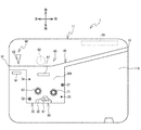
- 3 is a plan view of a main body case 11.
- FIG. It is a top view of the main body case 11 with which the tube 9 and the ribbon cassette 100 were mounted
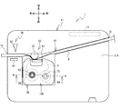
- FIG. 4 is a cross-sectional view taken along the line AA in FIG. 3.
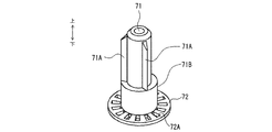
- 6 is a perspective view of a detection rotating shaft 71.
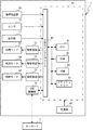
- FIG. FIG. 2 is a block diagram illustrating an electrical configuration of the printing apparatus 1. It is the perspective view which looked at the ribbon cassette 100 from the upper left rear. 2 is a plan view of the ribbon cassette 100.
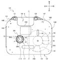
- FIG. 2 is a bottom view of the ribbon cassette 100.
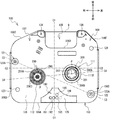
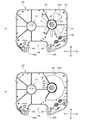
- FIG. 3 is a plan view of a lower case 103.
- FIG. 4 is a bottom view of the upper case 102.
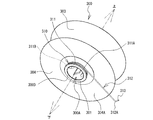
- FIG. It is the perspective view which looked at the winding spool 300 and the clutch spring 310 from the downward direction.
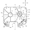
- 4 is a plan view of the lower case 103 when an external force F is applied to the ink ribbon 8.
- FIG. It is a bottom view of the upper case in a modification.
- the lower left, upper right, upper left, lower right, upper and lower in FIG. 1 are defined as the front, rear, left, right, upper, and lower sides of the printing apparatus 1, respectively.
- the upper right, lower left, lower right, upper left, upper and lower in FIG. 7 are defined as the front, rear, left, right, upper and lower of the ribbon cassette 100, respectively.
- the printing apparatus 1 is an apparatus that performs printing while conveying a tube 9 that is a cylindrical print medium, and cuts the tube 9 after printing.
- the printing apparatus 1 includes a housing 10 including a main body case 11 and a cover 12.
- the main body case 11 is a rectangular parallelepiped box-shaped member that is long in the left-right direction.
- the cover 12 is a plate-like member disposed on the upper side of the main body case 11.
- the rear end portion of the cover 12 is rotatably supported by the rear upper end portion of the main body case 11.
- the lock mechanism 13 is provided at the front upper end of the main body case 11.
- the lock mechanism 13 locks the front end portion of the cover 12 that is closed with respect to the main body case 11 to restrict the opening of the cover 12.
- the cover 12 When the cover 12 is closed with respect to the main body case 11 (see FIG. 1), the cover 12 covers the mounting surface 11A (see FIG. 2).
- the mounting surface 11 ⁇ / b> A is an upper surface of the main body case 11.
- the keyboard 7 is detachably mounted on the upper surface of the cover 12.
- the keyboard 7 includes an operation unit 7A having a plurality of keys and a display unit 7B for displaying a screen including various information.
- the user can edit the character to be printed on the tube 9 on the screen displayed on the display unit 7B by operating the operation unit 7A. Characters include letters, figures, symbols, and the like.
- a USB (Universal Serial Bus) cable 79 is connected to a board (not shown) in the keyboard 7. The USB cable 79 is drawn rightward from the right side surface of the keyboard 7.
- the operation unit 17 is a plurality of operation buttons including a power button and a start button provided on the front right side of the main body case 11.
- the tube insertion opening 15 is an opening provided in the upper part on the rear side of the right surface of the main body case 11 for guiding the tube 9 into the housing 10.
- the tube discharge port 16 is an opening provided in the upper part on the rear side of the left surface of the main body case 11 for discharging the tube 9 to the outside of the housing 10.
- the tube discharge port 16 is slightly in front of the tube insertion port 15.
- the mounting surface 11A is provided with a ribbon mounting portion 30, a tube mounting portion 40, and the like.
- the ribbon mounting part 30 is a part where the ribbon cassette 100 can be attached and detached.
- the ribbon mounting portion 30 is a recess that opens upward and is formed in an opening shape that is slightly larger than the ribbon cassette 100 in plan view.
- the rear part of the ribbon mounting part 30 communicates with a tube mounting part 40 described later in the front-rear direction.
- the ribbon mounting portion 30 of this example is provided on the left side of the mounting surface 11 ⁇ / b> A and on the front side of the tube mounting portion 40. The user mounts the ribbon cassette 100 on the ribbon mounting unit 30 from above so that the vertical and horizontal and front and rear directions of the ribbon cassette 100 coincide with the vertical and horizontal and front and rear directions of the printing apparatus 1.
- Positioning pins 31 and 32, support pins 33 and 34, and a support portion 35 are provided inside the ribbon mounting portion 30.
- the positioning pins 31 and 32 and the support pins 33 and 34 are all cylindrical shafts extending upward from the bottom surface 30 ⁇ / b> A of the ribbon mounting portion 30.
- the upper ends of the positioning pins 31 and 32 and the support pins 33 and 34 are all at the same vertical position (ie, height position).
- the positioning pins 31 and 32 have the same diameter.
- the support pins 33 and 34 have the same diameter as each other and a smaller diameter than the positioning pins 31 and 32.
- the positioning pins 31 and 32 are provided at positions corresponding to the positioning holes 121 and 122 (see FIG. 9) of the ribbon cassette 100 mounted on the ribbon mounting unit 30, respectively.
- the support pins 33 and 34 are provided at positions corresponding to the pin holes 123 and 124 (see FIG. 9) of the ribbon cassette 100 mounted on the ribbon mounting unit 30, respectively.
- the positioning pin 31 and the support pin 33 are respectively provided on the right rear side and the right front side of a later-described detection rotation shaft 71 and are arranged substantially in the front-rear direction.
- the positioning pin 32 and the support pin 34 are respectively provided on the left front side and the left rear side of a ribbon take-up shaft 63 which will be described later, and are aligned in the front-rear direction.
- the front-rear direction distance between the positioning pin 32 and the support pin 34 is slightly larger than the front-rear direction distance between the positioning pin 31 and the support pin 33.
- the support portion 35 is a stepped portion protruding upward from the bottom surface 30A.
- the upper end surface of the support portion 35 is at the same vertical position (ie, height position) as the upper end portions of the positioning pins 31 and 32 and the support pins 33 and 34.
- the support portion 35 is provided at a position corresponding to the front concave portion 125 (see FIG. 9) of the ribbon cassette 100 attached to the ribbon attachment portion 30.
- the support part 35 is provided on a line connecting the print head 61 and the front and rear direction and the positioning pin 32 and the support pin 33.
- the upper end surface of the support portion 35 is a flat surface corresponding to the front concave portion 125 in plan view.
- the tube mounting part 40 is a part where the tube 9 can be attached and detached.
- the tube mounting portion 40 is a groove portion that extends upward from the tube insertion port 15 to the vicinity of the right side of the tube discharge port 16 and opens upward. Since the tube discharge port 16 is slightly in front of the tube insertion port 15, the tube mounting portion 40 is slightly inclined to the left front side and extends in the substantially left-right direction. A direction in which the tube mounting portion 40 extends from the tube insertion port 15 toward the tube discharge port 16 is referred to as a tube conveyance direction. The user attaches the tube 9 to the tube attachment portion 40 along the tube conveyance direction so that the tube 9 extends from the tube insertion port 15 to the tube discharge port 16.
- the control board 19 is a board that controls the operation of the printing apparatus 1. As shown in FIG. 2, the control board 19 of this example is provided in the right rear part in the inside of the main body case 11, and connects with the USB connection part 18 (refer FIG. 6).
- the USB connection portion 18 is exposed to the outside of the main body case 11 from a plug housing portion 10A (see FIG. 1) formed at the lower right side of the housing 10 (see FIG. 1).
- a USB cable 79 (see FIG. 1) pulled out from the keyboard 7 is connected to the USB connection unit 18 via the plug housing unit 10A.
- the printing mechanism 60 includes a print head 61, a movable conveyance roller 62, a ribbon take-up shaft 63, a conveyance motor 64 (see FIG. 6), and the like.
- the print head 61 and the ribbon take-up shaft 63 are erected upward from the bottom surface 30A.
- the print head 61 and the ribbon take-up shaft 63 extend above the positioning pins 31 and 32, the support pins 33 and 34, and the support part 35.
- the print head 61 is a thermal head provided with a heating element (not shown).
- the print head 61 is provided at a position corresponding to the head insertion portion 109 (see FIG. 7) of the ribbon cassette 100 attached to the ribbon attachment portion 30.
- the print head 61 is provided in the approximate center of the rear part of the ribbon mounting part 30.
- the ribbon take-up shaft 63 is a shaft that can rotate together with a take-up spool 300 (see FIG. 4) of the ribbon cassette 100 described later.
- On the outer peripheral surface of the ribbon take-up shaft 63 there are provided a plurality of projecting pieces 63A that are arranged radially and equidistantly about the axis of the ribbon take-up shaft 63 (see FIG. 4).
- Each protruding piece 63 ⁇ / b> A protrudes radially outward from the outer peripheral surface of the ribbon winding shaft 63 and extends downward from the vicinity of the upper end portion of the ribbon winding shaft 63.
- the ribbon take-up shaft 63 is provided at a position corresponding to the first support hole 111 (see FIG. 7) of the ribbon cassette 100 attached to the ribbon attachment unit 30.
- the ribbon take-up shaft 63 is in front of the support pin 34 and behind the positioning pin 32 in the left part of the ribbon mounting portion 30.
- the movable conveyance roller 62 is a roller that can rotate relative to the print head 61.
- the movable conveyance roller 62 is disposed behind the ribbon mounting portion 30 and can be displaced between a retracted position and an operating position as the cover 12 (see FIG. 1) is opened and closed.
- the movable conveyance roller 62 is disposed behind the tube mounting portion 40 and is separated from the print head 61 (see FIG. 2).
- the movable conveyance roller 62 is in the operating position, a part of the movable conveyance roller 62 is disposed inside the tube mounting portion 40 and is close to the print head 61 (see FIG. 3).
- the conveyance motor 64 is a motor that rotationally drives the movable conveyance roller 62 and the ribbon take-up shaft 63.
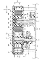
- a disk-shaped gear 65 that can rotate around the ribbon take-up shaft 63 is provided in the vicinity of the lower end of the ribbon take-up shaft 63.
- the gear 65 is connected to a fixing member 67 fixed around the ribbon take-up shaft 63 via a one-way clutch 66.
- the one-way clutch 66 stably rotates the ribbon take-up shaft 63 by the elastic force of the clutch spring, and the ribbon take-up shaft 63 has a predetermined take-up direction (in this example, a counterclockwise direction in plan view). Restricts rotation in the opposite direction (hereinafter referred to as the reverse direction).
- the transport motor 64 rotates the ribbon winding shaft 63 in the winding direction via the one-way clutch 66 and the fixing member 67 by rotating the gear 65 counterclockwise in plan view.
- the movable transport roller 62 (see FIG. 2) rotates in a clockwise direction in a plan view via a gear group (not shown) interlocked with the gear 65.
- the movable conveyance roller 62 and the ribbon take-up shaft 63 rotate in synchronization.
- the transport amount detection unit 70 is a member for detecting the transport amount of the ink ribbon 8 during the printing operation.
- the carry amount detection unit 70 includes a detection rotating shaft 71, a detection plate 72, and a sensor 73.
- the detection rotating shaft 71 is erected upward from the bottom surface 30A (see FIG. 2).
- the detection rotating shaft 71 extends to a position higher than the positioning pins 31 and 32, the support pins 33 and 34, and the support portion 35.
- the upper end portion of the detection rotating shaft 71 is below the upper end portions of the print head 61 and the ribbon take-up shaft 63.
- the detection rotating shaft 71 is a shaft that can rotate together with a ribbon spool 200 of the ribbon cassette 100 described later.
- the detection rotary shaft 71 is provided at a position corresponding to the second support hole 112 (see FIG. 9) of the ribbon cassette 100 mounted on the ribbon mounting portion 30.
- the detection rotating shaft 71 is on the front side of the positioning pin 31 and on the rear side of the support pin 33 in the right part of the ribbon mounting portion 30.
- the axis of the detection rotating shaft 71 is slightly in front of the axis of the ribbon take-up shaft 63.
- the detection rotating shaft 71 has a plurality of protruding pieces 71 ⁇ / b> A, a cylindrical portion 71 ⁇ / b> B, and a detection plate 72.
- the cylindrical portion 71 ⁇ / b> B is a cylindrical member that is provided around the detection rotation shaft 71 and that can rotate together with the detection rotation shaft 71.
- the plurality of projecting pieces 71A are provided on the outer peripheral surface of the cylindrical portion 71B, and are arranged radially and at equal intervals around the axis of the rotation shaft 71 for detection.
- Each protruding piece 71A protrudes radially outward from the outer peripheral surface of the cylindrical portion 71B and extends downward from the vicinity of the upper end portion of the cylindrical portion 71B.
- the detection plate 72 has a disk shape that protrudes radially outward from the vicinity of the lower end of the cylindrical portion 71B.
- the plan view center of the detection plate 72 coincides with the axis of the detection rotation shaft 71.
- the detection plate 72 is provided with a plurality of detection holes 72A.
- the plurality of detection holes 72A are holes that pass through the detection plate 72 in the vertical direction and are arranged radially and at equal intervals around the center of the detection plate 72 in plan view.
- the sensor 73 is a transmissive photosensor having a light emitting part 73A and a light receiving part 73B.
- the light emitting unit 73A and the light receiving unit 73B are disposed opposite to each other on both the upper and lower sides with the detection plate 72 interposed therebetween.
- the CPU 41 (see FIG. 6) irradiates light from the light emitting unit 73A toward the light receiving unit 73B during the printing operation.
- the light emitted from the light emitting unit 73A passes through any of the plurality of detection holes 72A and is received by the light receiving unit 73B.
- the sensor 73 outputs an ON signal to the CPU 41.
- the sensor 73 outputs an OFF signal to the CPU 41.
- the sensor 73 may be a reflective photosensor that can detect the light reflected by the detection plate 72.
- the index detection unit 80 is a member for detecting the type index unit 190 (see FIG. 9) of the ribbon cassette 100.
- the index detection unit 80 includes five detection switches 81 provided on a substrate (not shown).
- Each detection switch 81 is a mechanical switch that can advance and retreat in the vertical direction.
- Each of the five detection switches 81 is movable in the vertical direction through a hole formed in the upper end surface of the support portion 35.
- the five detection switches 81 are provided at positions respectively corresponding to the indicator portions 191 to 195 (see FIG. 9) of the ribbon cassette 100 attached to the ribbon attachment portion 30.
- four detection switches 81 are arranged side by side in the left-right direction. Among the four detection switches 81, the remaining one detection switch 81 is arranged behind the second detection switch 81 from the left.
- Each detection switch 81 is biased upward by a spring (not shown).
- the detection switch 81 to which no external force is applied is located at a reference position moved upward from the support portion 35 by a biasing force of a spring (not shown).
- the index detection unit 80 outputs an OFF signal corresponding to the detection switch 81 at the reference position to a CPU 41 (see FIG. 6) described later.
- the detection switch 81 is pressed from above, it moves to a pressed position below the reference position.
- the index detection unit 80 outputs an ON signal corresponding to the detection switch 81 at the pressed position to the CPU 41.
- a combination of the ON signal and the OFF signal of the five detection switches 81 is referred to as a type detection pattern.
- the cutting mechanism 90 is a mechanism that executes a cutting operation of the tube 9. As shown in FIG. 2, the cutting mechanism 90 is provided in the vicinity of the left end portion of the tube mounting portion 40 in the main body case 11. That is, the cutting mechanism 90 is on the downstream side of the print head 61 in the tube conveyance direction.
- the cutting mechanism 90 includes a cradle 91, a cutting blade 92, and a cutting motor 93 (see FIG. 6).
- the cradle 91 is provided in front of the left end portion of the tube mounting portion 40 and has a rectangular parallelepiped shape.
- the cutting blade 92 faces the cradle 91 from behind with the tube mounting portion 40 interposed therebetween.
- the cutting motor 93 moves the cutting blade 92 in the front-rear direction so that the cutting blade 92 approaches or separates from the cradle 91.
- the control board 19 includes a CPU 41, a ROM 42, a RAM 44, a flash memory 45, an input / output interface 49, and the like, which are connected via a data bus.
- the ROM 42 stores a program for the CPU 41 to execute various controls including a printing operation.
- the RAM 44 temporarily stores various data.
- the flash memory 45 stores a table that defines ribbon types corresponding to the type detection patterns. For example, the ribbon type is the color and width of the ink ribbon 8 accommodated in the ribbon cassette 100.
- the printing apparatus 1 has a power supply unit 48.
- the power supply unit 48 is connected to a battery (not shown) mounted in the main body case 11 or connected to an external power supply (not shown) via a cord, and supplies power to the control board 19.
- the operation unit 17, the USB connection unit 18, the drive circuits 51 to 53, the sensor 73, and the index detection unit 80 are connected to the input / output interface 49, respectively.
- the USB connection unit 18 is connected to the keyboard 7 via the USB cable 79 (see FIG. 1).
- the CPU 41 receives various types of information input via the operation unit 17.
- the CPU 41 receives various instructions input via the operation unit 7A (see FIG. 1) and controls display of the screen of the display unit 7B.
- the CPU 41 receives the ON / OFF signal output from the sensor 73 and the type detection pattern output from the index detection unit 80.
- the drive circuits 51 to 53 are connected to the print head 61, the transport motor 64, and the cutting motor 93, respectively.
- the CPU 41 drives and controls the print head 61 by transmitting a control signal to the drive circuit 51.
- the CPU 41 drives and controls the conveyance motor 64 by transmitting a pulse signal to the drive circuit 52.
- the CPU 41 controls the cutting motor 93 by transmitting a control signal to the driving circuit 53.
- the ribbon cassette 100 will be described with reference to FIGS. 7 to 10 illustrate the ribbon cassette 100 in an initial state that is not used for the printing operation. In the ribbon cassette 100 in the initial state, all the ink ribbons 8 are unused. A predetermined upper limit amount of the ink ribbon 8 is wound around the ribbon spool 200. The ink ribbon 8 is not wound on the take-up spool 300 (the same applies to FIG. 4 described above).
- the ribbon cassette 100 has a case 101 for accommodating the ink ribbon 8.
- the shape of the case 101 is a box shape that is long in the left-right direction and short in the up-down direction.
- the case 101 includes a lower case 103 and an upper case 102 assembled on the upper side of the lower case 103.
- the upper surface of the upper case 102 and the lower surface of the lower case 103 are the upper surface 104 and the lower surface 105 of the case 101, respectively.
- the upper surface 104 and the lower surface 105 face each other in the vertical direction and have substantially the same shape in plan view.
- a virtual line extending in the front-rear direction through the center in the left-right direction of the case 101 is a center line C1.
- a virtual line extending in the left-right direction through the center in the front-rear direction of the case 101 is a center line C2.
- the side surface 106 of the case 101 connects the upper surface 104 and the lower surface 105 in the vertical direction, and extends along outer edges of the upper surface 104 and the lower surface 105.
- the side surface 106 includes a front surface 106A, a right surface 106B, a left surface 106C, a head circumferential surface 106D, and connection surfaces 106E and 106F.
- the front surface 106A extends in the left-right direction.
- the right surface 106B and the left surface 106C extend rearward in parallel from the right end and the left end of the front surface 106A, respectively.
- the right surface 106B and the left surface 106C are arranged side by side in the left-right direction, and the lengths in the front-rear direction are substantially equal.
- the head circumferential surface 106D is a portion of the side surface 106 that is provided across the center line C1 in a plan view and is recessed forward from the rear end side of the case 101.
- the connection surface 106E extends rightward and forward from the right rear end portion of the head peripheral surface 106D, and is connected to the rear end portion of the right surface 106B.
- the connection surface 106F extends leftward from the left rear end portion of the head peripheral surface 106D, and is connected to the rear end portion of the left surface 106C.
- the length in the extending direction of the connecting surface 106E is larger than the length in the extending direction of the connecting surface 106F.
- the inner region surrounded by the head peripheral surface 106D is a head insertion portion 109.
- the head insertion portion 109 penetrates the case 101 in the vertical direction and opens to the rear of the case 101.
- the head insertion portion 109 has a substantially rectangular shape that is long in the left-right direction in plan view, and extends in the left-right direction across the center line C1.
- the center of the head insertion portion 109 in the left-right direction is slightly to the left of the center line C1.
- the part on the right side of the head insertion portion 109 in the case 101 is a first guide portion 107.
- the first guide portion 107 has a triangular shape in plan view surrounded by the right surface of the head circumferential surface 106D and the connection surface 106E.
- a ribbon outlet 107 ⁇ / b> A that is an opening communicating with the head insertion portion 109 is provided at the left rear end portion of the first guide portion 107.
- the ink ribbon 8 is conveyed from the inside of the case 101 to the outside through the ribbon outlet 107A.
- a portion of the case 101 on the left side of the head insertion portion 109 is a second guide portion 108.
- the second guide portion 108 has a triangular shape in plan view, surrounded by the left surface of the head circumferential surface 106D and the connection surface 106F.
- a ribbon inlet 108 ⁇ / b> A that is an opening communicating with the head insertion portion 109 is provided at the right rear end portion of the second guide portion 108.
- the ink ribbon 8 is conveyed from the outside of the case 101 to the inside through the ribbon inlet 108A. That is, a part of the ink ribbon 8 is exposed from the case 101 between the ribbon outlet 107A and the ribbon inlet 108A.
- the case 101 is provided with a first support hole 111 that rotatably supports the take-up spool 300 and a second support hole 112 (see FIG. 9) that rotatably supports the ribbon spool 200.
- the first support hole 111 is provided in the left part of the case 101, and is in front of the second guide part 108 and in the rear of a later-described front concave part 125.
- the first support hole 111 includes an upper hole 111A (see FIG. 8) that is a circular hole penetrating the upper case 102 in the vertical direction, and a lower hole 111B (see FIG. 9) that is a circular hole penetrating the lower case 103 in the vertical direction. ).
- the upper hole 111A and the lower hole 111B are holes having the same diameter arranged in the vertical direction.
- a rotation axis passing through the rotation center of the take-up spool 300 supported by the first support hole 111 is referred to as an axis J.
- the second support hole 112 is provided in the right part of the case 101 and is located in front of the first guide part 107 and in the rear part of the front concave part 125.
- the second support hole 112 is a circular hole that penetrates the lower case 103 in the vertical direction.
- a rotation axis passing through the rotation center of the ribbon spool 200 supported by the second support hole 112 is referred to as an axis P.
- the axes P and J are in front of the center line C2.
- the axis P is ahead of the axis J.
- the lower case 103 is provided with positioning holes 121, 122, pin holes 123, 124, and a front recess 125.
- the positioning holes 121 and 122 and the pin holes 123 and 124 are all concave portions that are recessed upward from the lower surface 105.
- the upper ends of the positioning holes 121 and 122 and the pin holes 123 and 124 are at height reference positions that are predetermined vertical positions in the case 101.
- the height reference position is a specified distance below the center of the case 101 in the vertical direction. The specified distance is constant regardless of the vertical length of the case 101 (that is, the thickness of the case 101).
- the positioning hole 121 and the pin hole 123 are provided on the right rear side and the right front side of the second support hole 112, respectively, and are aligned in the front-rear direction.
- the positioning hole 121 and the pin hole 123 are both in the vicinity of the right surface 106B.
- the positioning hole 122 and the pin hole 124 are provided on the left front side and the left rear side of the lower hole 111B, respectively, and are arranged substantially in the front-rear direction.
- the positioning hole 122 and the pin hole 124 are both in the vicinity of the left surface 106C.
- the positioning hole 122 and the pin hole 123 are behind the center line C2.
- the positioning hole 121 and the pin hole 124 are behind the center line C2.
- the distance in the front-rear direction of the positioning hole 122 and the pin hole 124 is larger than the distance in the front-rear direction of the positioning hole 121 and the pin hole 123.
- the lower portion of the positioning hole 121 has a circular opening shape.
- the opening width of the lower portion of the positioning hole 121 is slightly larger than the shaft diameter of the positioning pin 31 (see FIG. 2).
- the locking portion 121A which is the upper portion of the positioning hole 121, is a round hole that opens downward and is closed by a top surface (not shown) at the height reference position.
- the opening width of the locking portion 121 ⁇ / b> A is smaller than the lower portion of the positioning hole 121 and is the same diameter as the shaft diameter of the positioning pin 31.
- the lower part of the positioning hole 122 has a circular opening shape like the lower part of the positioning hole 121.
- the opening width of the lower portion of the positioning hole 122 is slightly larger than the shaft diameter of the positioning pin 32 (see FIG. 2).
- the locking portion 122A which is the upper portion of the positioning hole 122, is a hole that opens downward and is closed by a top surface (not shown) at the height reference position.
- the locking portion 122A is a long hole extending in the right rear direction and the left front direction.
- the minimum opening width of the locking portion 122A (that is, the length in the short direction of the locking portion 122A) is the same as the shaft diameter of the positioning pin 32.
- the locking portion 121A is disposed on the extended line in the longitudinal direction of the locking portion 122A.
- a virtual straight line connecting the centers of the locking portions 121A and 122A is a connecting line C3.
- the connecting line C3 extends substantially parallel to the longitudinal direction of the locking portion 122A.
- the axis J is on the left side of the connecting line C3.
- the axis P is on the right side of the connecting line C3.
- the pin holes 123 and 124 are round holes that are open downward and are closed by a top surface (not shown) whose upper end is at the height reference position.
- the opening widths of the pin holes 123 and 124 are slightly larger than the shaft diameters of the support pins 33 and 34, respectively.
- the opening widths of the pin holes 123 and 124 have the same diameter and are smaller than the opening widths of the lower portions of the positioning holes 121 and 122.
- the front recessed portion 125 is a stepped portion that is recessed upward from the lower surface 105.
- the upper end surface of the front recess 125 is at the height reference position.
- the front concave portion 125 of this example is located on the line connecting the head insertion portion 109 and the position aligned in the front-rear direction and the positioning hole 122 and the pin hole 123.
- the front recess 125 is provided at the front end of the lower case 103 and extends in the left-right direction across the center line C1.
- the left end portion of the front concave portion 125 is at a position substantially equal to the left end portion of the head insertion portion 109 in the left-right direction.
- the right end portion of the front recess 125 is slightly to the right of the right end portion of the head insertion portion 109 in the left-right direction.
- the center in the left-right direction of the front recess 125 is slightly to the left of the center line C1.
- the front recess 125 extends rearward along the center line C1 when viewed from the bottom.
- the rear end portion of the front concave portion 125 is substantially at the same position as the pin hole 123 in the front-rear direction.
- a type indicator 190 indicating the ribbon type is provided on the upper end surface of the front recess 125.
- An imaginary straight line connecting the axes J and P is a connecting line C4.
- the type indicator 190 is on the front side of the connecting line C4 and is aligned with the head circumferential surface 106D in the front-rear direction.
- the type indicator portion 190 of this example includes five indicator portions 191 to 195.
- the indicator portions 191 to 194 are arranged in the left-right direction along the front surface 106A.
- the index unit 195 is disposed behind the second index unit 193 from the left among the index units 191 to 194.
- Each of the indicator portions 191 to 195 has a pattern corresponding to the ribbon type of the ribbon cassette 100, and is configured with either a surface portion or a hole portion.
- the indicator portions 191 to 193 and 195 are holes, and the indicator portion 194 is a surface portion.
- the ink ribbon 8 is accommodated in the case 101 in a posture in which the width direction (short direction) is substantially parallel to the vertical direction.
- a ribbon spool 200 and a take-up spool 300 are provided inside the case 101.
- the ink ribbon 8 is transported from the ribbon spool 200 to the take-up spool 300 via a predetermined transport path (hereinafter referred to as a ribbon transport path) in a posture in which the width direction is substantially parallel to the vertical direction.
- the direction in which the ink ribbon 8 is transported along the ribbon transport path is referred to as the ribbon transport direction.
- the ribbon spool 200 is a cylindrical member extending in the vertical direction, and is wound around one end side in the longitudinal direction of the ink ribbon 8 (that is, the upstream side in the ribbon transport direction).
- the take-up spool 300 is a cylindrical member extending in the vertical direction, and is connected to the other end side in the longitudinal direction of the ink ribbon 8 (that is, the downstream side in the ribbon transport direction).
- a mounting hole 200A penetrating in the vertical direction is provided.
- the outer peripheral surface of the ribbon spool 200 is a supply surface 200B around which the unused ink ribbon 8 is wound.
- the unused ink ribbon 8 is wound around the supply surface 200B so that the ink surface to which the ink is applied is the inside of both surfaces of the ink ribbon 8.
- the upper limit amount of the ink ribbon 8 can be wound around the supply surface 200B.
- the ink ribbon 8 wound around the supply surface 200B is referred to as a first ribbon roll 8A.
- the outer diameter of the first ribbon roll 8A becomes the maximum value when the upper limit amount of the ink ribbon 8 is wound around the supply surface 200B.
- the upper limit amount of the ink ribbon 8 wound around the ribbon spool 200 is referred to as a maximum diameter first ribbon roll 8A.
- the upper and lower ends of the ribbon spool 200 are provided with protrusions 200C and 200D, respectively.
- the protruding portion 200C protrudes above the supply surface 200B.
- the protrusion 200D protrudes downward from the supply surface 200B.
- the inner surface 102A of the upper case 102 is provided with a support portion 140 that faces the second support hole 112 in the vertical direction (see FIG. 11).
- the protruding portion 200 ⁇ / b> C is attached to the support portion 140 from below and is rotatably supported by the support portion 140.
- the protruding portion 200 ⁇ / b> D is fitted into the second support hole 112 from above and is rotatably supported by the second support hole 112. That is, the ribbon spool 200 is rotatably supported by the second support hole 112 and the support part 140. Accordingly, the axis P substantially coincides with the center of the second support hole 112 in plan view.
- a cylindrical rotating member 290 around which a clutch spring 280 is wound is mounted on the mounting hole 200A. An end portion of the clutch spring 280 is locked to the support portion 140.
- the rotating member 290 can rotate together with the ribbon spool 200.
- the clutch spring 280 is expanded in diameter, and therefore the ribbon spool is interposed via the rotating member 290.
- the rotational load applied to 200 is relatively small.
- the rotational load is a load that acts to prevent the rotation of the member.
- the rotational load applies a rotational torque to the ribbon spool 200. The rotational torque does not change depending on the outer diameter of the first ribbon roll 8A and is stably generated.
- the clutch spring 280 is reduced in diameter, so that the rotational load applied to the ribbon spool 200 via the rotating member 290 is reduced. Is relatively large. That is, the rotating member 290 stably rotates the ribbon spool 200 in the pull-out direction by the elastic force of the clutch spring 280 and restricts the ribbon spool 200 from rotating in the direction opposite to the pull-out direction.
- the take-up spool 300 includes a main body 301, a plurality of engaging protrusions 302, an upper support plate 303, a lower support plate 304, and the like.
- the main body 301 is a cylindrical body extending in the vertical direction.
- a mounting hole 300 ⁇ / b> A penetrating in the vertical direction is provided inside the main body 301.
- Each of the plurality of engagement protrusions 302 protrudes from the inner peripheral surface of the main body 301 toward the axis J.
- the plurality of engaging protrusions 302 are arranged radially and equidistantly about the axis J.
- the outer peripheral surface of the main body 301 is a winding surface 300B on which the used ink ribbon 8 is wound.
- the used ink ribbon 8 is wound around the winding surface 300B along the winding direction (the direction of the arrow R1) so that the ink surface of both surfaces of the ink ribbon 8 is outside.
- the upper limit amount of the ink ribbon 8 can be wound around the winding surface 300B.
- the ink ribbon 8 wound around the winding surface 300B is referred to as a second ribbon roll 8B (see FIG. 3).
- the outer diameter of the second ribbon roll 8B becomes the maximum value when the upper limit amount of the ink ribbon 8 is wound around the winding surface 300B.
- the upper limit amount of the ink ribbon 8 wound around the take-up spool 300 is referred to as a maximum diameter second ribbon roll 8B.
- the upper support plate 303 has a disk shape extending radially outward from the vicinity of the upper end of the main body 301.
- the lower support plate 304 has a disk shape extending radially outward from the vicinity of the lower end of the main body 301.
- the upper support plate 303 and the lower support plate 304 are plate-like members having the same diameter and arranged to face each other in the vertical direction.
- the vertical distance between the upper support plate 303 and the lower support plate 304 is slightly larger than the length in the width direction of the ink ribbon 8. Accordingly, the second ribbon roll 8B is held between the upper support plate 303 and the lower support plate 304.
- a region surrounded by the upper support plate 303, the lower support plate 304, and the winding surface 300B is a storage portion 305 that can store the second ribbon roll 8B.
- the outer diameter of the accommodating portion 305 (that is, the outer diameter of each of the upper support plate 303 and the lower support plate 304) is larger than the outer diameter of the second ribbon roll 8B having the maximum diameter.
- the upper support plate 303 is above the supply surface 200B.
- the lower support plate 304 is below the supply surface 200B.
- the right end portions of the upper support plate 303 and the lower support plate 304 are between the center line C1 and the ribbon spool 200. That is, the accommodating part 305 is close to the supply surface 200B from the left side.
- a part of the first ribbon roll 8A enters the housing portion 305 from the right side. In other words, when the radius of the first ribbon roll 8A exceeds the distance from the axis P to the storage unit 305, a part of the first ribbon roll 8A is disposed in the storage unit 305.
- the case 101 can be further downsized.
- the outer diameter of the second ribbon roll 8B increases and the outer diameter of the first ribbon roll 8A decreases. Therefore, the first ribbon roll 8A and the second ribbon roll 8B can be prevented from interfering with each other.
- Projection portions 300C and 300D are provided on the upper end portion and the lower end portion of the take-up spool 300, respectively.
- the protruding portion 300C protrudes above the upper support plate 303.
- the protrusion 300D protrudes below the lower support plate 304.
- the protrusion 300C is fitted into the upper hole 111A from below and is rotatably supported by the upper hole 111A.
- the protrusion 300D is fitted into the lower hole 111B from above and is rotatably supported by the lower hole 111B. That is, the take-up spool 300 is rotatably supported by the first support hole 111. Therefore, the axis J substantially coincides with the center of the first support hole 111 in plan view.
- a metal clutch spring 310 is provided below the lower support plate 304.
- the clutch spring 310 is a spring member for returning the slackened ink ribbon 8 to a state where an appropriate tension is applied.
- the clutch spring 310 includes a coiled winding portion 311 and an extending portion 312 extending from the upper end portion 311A of the winding portion 311.
- the winding portion 311 extends from the upper end portion 311A of the winding portion 311 to the lower end portion 311B of the winding portion 311 in the direction opposite to the winding direction (that is, the reverse direction, the direction of the arrow R2) and protrudes.
- a plurality of turns (three turns in this example) are wound around the outer peripheral surface of the portion 300D.
- the upper end 311A is in contact with the lower surface 304A of the lower support plate 304.
- the lower end 311B is located below the upper end 311A (that is, in a direction away from the lower support plate 304).
- the extending portion 312 is straight from the upper end portion 311A in the tangential direction along the lower support plate 304 to the vicinity of the head peripheral surface 106D (that is, a position farther from the axis J than the engaging portion 150 described later in plan view). It extends in a shape. A portion of the extended portion 312 that is on the inner side of the outer diameter edge of the lower support plate 304 from the upper end portion 311A is in contact with the lower surface 304A. The vicinity of the distal end portion 312 ⁇ / b> A of the extending portion 312 is engaged with an engaging portion 150 described later provided on the case 101.
- the extending portion 312 has a locking portion 313 that extends in the direction opposite to the axis J from the tip portion 312A to the upper end portion 311A.
- the locking portion 313 suppresses the clutch spring 310 from being detached in the extending direction of the extending portion 312 from an engaging portion 150 described later.
- the winding portion 311 When the take-up spool 300 rotates in the take-up direction (arrow R1 direction), the winding portion 311 is expanded in diameter, so that the rotational load applied to the take-up spool 300 is relatively small.
- the winding spool 300 rotates in the reverse rotation direction the winding portion 311 is reduced in diameter, so that the rotational load applied to the winding spool 300 is relatively large. That is, the clutch spring 310 stably rotates the take-up spool 300 in the take-up direction by elastic force and restricts the take-up spool 300 from rotating in the reverse direction.
- an engagement portion 150 and a plurality of bent portions 131 to 137 are provided inside the case 101.
- the engaging portion 150 is a member for restricting movement of the clutch spring 310 in the winding direction and the reverse direction.
- the engaging portion 150 is provided in the vicinity of the center line C1 and the head circumferential surface 106D in plan view. That is, the engaging portion 150 is provided between the axis J and the axis P and behind the connecting line C4 in plan view.
- the distance from the upper end portion 311A to the engaging portion 150 is smaller than the length from the upper end portion 311A to the distal end portion 312A and larger than the distance from the distal end portion 312A to the engaging portion 150.
- the engaging portion 150 is provided at a position near the tip portion 312A among the upper end portion 311A and the tip portion 312A in plan view.
- the distance from the axis P to the engaging portion 150 is larger than the radius of the first ribbon roll 8A having the maximum diameter. That is, the engaging portion 150 is provided at a position farther from the axis P than the outermost periphery of the first ribbon roll 8A having the maximum diameter in plan view.
- the distance from the axis J to the engaging part 150 is larger than the radius of the second ribbon roll 8B having the maximum diameter. That is, the engaging portion 150 is provided at a position farther from the axis J than the outermost circumference of the second ribbon roll 8B having the maximum diameter in plan view.
- the engaging part 150 has a first engaging part 151 and a second engaging part 152.
- the first engaging portion 151 is erected on the inner surface 103A of the lower case 103 in the vicinity of the head circumferential surface 106D and slightly to the left of the center line C1.
- the first engagement portion 151 is a plate-like member that extends to the right front and upward.
- the second engaging portion 152 is erected on the inner surface 103A at a position slightly separated from the first engaging portion 151 to the right front.
- the second engaging portion 152 is a plate-like member that extends to the front right and upward.
- the first engaging portion 151 and the second engaging portion 152 face each other with the extending portion 312 interposed therebetween.
- the mutually opposing surfaces in the first engaging portion 151 and the second engaging portion 152 are referred to as a first opposing surface 151A and a second opposing surface 152A, respectively.
- the first engaging portion 151 regulates the movement of the extending portion 312 in the winding direction when the extending portion 312 contacts the first facing surface 151A.
- the second engaging portion 152 regulates the movement of the extending portion 312 in the reverse rotation direction when the extending portion 312 contacts the second facing surface 152A.
- the bent portions 131 to 137 are members for setting the ribbon conveyance path and are members for meandering the ribbon conveyance path. Each of the bent portions 131 to 137 is erected on the inner surface 103A and extends upward to the upper case 102.
- the bent portions 131, 132, and 136 are cylindrical bodies fixed to the lower case 103. Specifically, the bent portions 131, 132, and 136 are formed integrally with the lower case 103.
- the bent portions 133 to 135, 137 are cylindrical rotating bodies that can rotate around an axis extending in the vertical direction.
- the bent portions 131 to 134 are provided at the right rear portion of the case 101.
- the bent portion 131 is on the right rear side of the second support hole 112 (see FIG. 9) in plan view.
- the positioning hole 121 is between the bent portion 131 and the ribbon spool 200 in the front-rear direction.
- the bent portion 131 is between the positioning hole 121 and the ribbon spool 200 in the left-right direction.
- the bent portion 131 is between the head peripheral surface 106D and the ribbon spool 200 in the front-rear direction.
- the distance from the axis P to the bent portion 131 is larger than the radius of the first ribbon roll 8A having the maximum diameter.
- the bent portions 132 to 134 are in the first guide portion 107.
- the bent portion 132 is on the left rear side of the bent portion 131.
- the bent portion 133 is on the left side of the bent portion 132.
- the bent portion 134 is on the left rear side of the bent portion 133 and is on the left rear portion of the first guide portion 107.
- the bent portions 135 to 137 are provided at the left rear portion of the case 101.
- the bent portions 135 to 137 are in the second guide portion.
- the bent portion 137 is on the left rear side of the first support hole 111 (see FIG. 8).
- the distance from the axis J to the bent portion 137 is larger than the radius of the maximum diameter second ribbon roll 8B (see FIG. 3).
- the bent portion 136 is on the left rear side of the bent portion 137.
- the bent portion 135 is on the right rear side of the bent portion 136 and on the right rear portion of the second guide portion 108.
- a window portion 160 and at least one elastic body 180 are provided around the support portion 140 in the upper case 102.
- the window portion 160 is a long hole that penetrates the upper case 102 in the vertical direction and extends in the radial direction with the support portion 140 as the center.
- the window portion 160 of this example extends rearward from the rear side of the support portion 140.
- the rear end portion of the window portion 160 is outside the first ribbon roll 8A having the maximum diameter in plan view. The user can recognize the remaining amount of the unused ink ribbon 8 by viewing the outer diameter position of the first ribbon roll 8 ⁇ / b> A through the window portion 160.
- Each elastic body 180 is a plate-like sponge provided on the inner surface 102A. Each elastic body 180 extends in the radial direction around the support portion 140. Each elastic body 180 extends from the outer edge of the support portion 140 to the outside of the maximum diameter first ribbon roll 8A in plan view. As shown in FIG. 4, each elastic body 180 is in elastic contact with the first ribbon roll 8 ⁇ / b> A from above inside the case 101. That is, each elastic body 180 is in surface contact over the entire radial direction on the upper surface of the first ribbon roll 8A, and biases the first ribbon roll 8A downward. In this example, two elastic bodies 180 are disposed on the front side and the right rear side of the support part 140.
- Each elastic body 180 is the same plate-like sponge having a fan shape with a thickness of 4 mm, and is attached to the inner surface 102A by a double-sided tape not shown. With each elastic body 180 in elastic contact with the first ribbon roll 8A, the thickness of each elastic body 180 is about 2 mm.
- the detection rotating shaft 71 is inserted into the mounting hole 200 ⁇ / b> A of the ribbon spool 200 through the second support hole 112.
- the plurality of protruding pieces 71A are engaged with the ribbon spool 200 in the mounting hole 200A, similarly to the plurality of protruding pieces 63A.
- the ribbon cassette 100 mounted on the ribbon mounting unit 30 is positioned at an appropriate position in the ribbon mounting unit 30 as follows.
- the positioning pins 31 and 32 and the support pins 33 and 34 are inserted into the positioning holes 121 and 122 and the pin holes 123 and 124, respectively.
- the upper end portion of the support pin 33 contacts the top surface of the pin hole 123 to position the ribbon cassette 100 in the vertical direction.
- the upper end portion of the support pin 34 contacts the top surface of the pin hole 124 to position the ribbon cassette 100 in the vertical direction.
- the upper end portion of the positioning pin 31 is closely fitted into the locking portion 121A to position the ribbon cassette 100 in the up, down, left, right, front and rear directions.
- the upper end portion of the positioning pin 32 is closely fitted into the locking portion 122 ⁇ / b> A to position each direction of the ribbon cassette 100 in the vertical and horizontal directions.
- the support portion 35 supports the front concave portion 125 from below and positions the ribbon cassette 100 in the vertical direction.
- each of the indicator portions 191 to 195 faces one of the five detection switches 81.
- Each detection switch 81 facing the index portions 191 to 193 and 195 is inserted into the hole and held at the reference position.
- the detection switch 81 facing the indicator portion 194 is pressed by the surface portion and displaced to the pressed position.
- the index detection unit 80 outputs a combination of an OFF signal corresponding to each detection switch 81 at the reference position and an ON signal corresponding to the detection switch 81 at the pressed position to the CPU 41 (see FIG. 6) as a type detection pattern.
- the CPU 41 specifies the ribbon type corresponding to the received type detection pattern with reference to the table of the flash memory 45 (see FIG. 6). Thereby, the printing apparatus 1 can specify the ribbon type of the ribbon cassette 100 mounted on the ribbon mounting unit 30.
- the cover 12 is closed in a state where the ribbon cassette 100 is mounted on the ribbon mounting portion 30 and the tube 9 is mounted on the tube mounting portion 40.
- the movable conveyance roller 62 is displaced to the operating position.
- the movable conveyance roller 62 urges the tube 9 in the tube mounting portion 40 and the unused ink ribbon 8 to overlap the print head 61.
- the tube 9 is elastically deformed by the urging force of the movable conveyance roller 62 and comes into surface contact with the print head 61 via the ink ribbon 8.
- the CPU 41 drives the transport motor 64 to rotate the movable transport roller 62 and the ribbon take-up shaft 63.
- the tube 9 in the tube mounting portion 40 is transported downstream in the tube transport direction as the movable transport roller 62 rotates. At this time, the tube 9 before printing outside the housing 10 is drawn into the tube mounting portion 40 through the tube insertion port 15.
- the take-up spool 300 rotates in the take-up direction (arrow R1 direction). In this case, the winding part 311 is expanded in diameter.
- the take-up spool 300 rotates, the ribbon spool 200 rotates in the drawing direction (arrow R3 direction). As a result, the ink ribbon 8 is pulled out from the vicinity of the rear end of the first ribbon roll 8A and conveyed along the following ribbon conveyance path.
- a relatively small rotational load is applied to the ribbon spool 200 by the elastic force of the clutch spring 280. As a result, an appropriate tension is applied to the conveyed ink ribbon 8, so that the ink ribbon 8 does not loosen easily.
- the unused ink ribbon 8 After the unused ink ribbon 8 is pulled out from the first ribbon roll 8A, the right front surface side of the bent portion 131, the right rear surface side of the bent portion 132, the left front surface side of the bent portion 133, and the right rear surface side of the bent portion 134 Go through in order.
- the unused ink ribbon 8 is discharged from the ribbon outlet 107 ⁇ / b> A to the outside of the case 101 and proceeds leftward in the head insertion portion 109. At this time, the unused ink ribbon 8 passes between the tube 9 and the print head 61.
- the CPU 41 drives the print head 61 to heat the ink ribbon 8 passing between the tube 9 and the print head 61 to print the character on the tube 9.
- the print head 61 of this example prints a normal image of the character on the front part of the tube 9 passing through the rear side.
- the CPU 41 drives the cutting motor 93 to bring the cutting blade 92 closer to the cradle 91, thereby cutting the printed tube 9.
- the cut tube 9 is discharged to the outside of the housing 10 through the tube discharge port 16.
- the used ink ribbon 8 enters the inside of the case 101 from the ribbon inlet 108A and passes through the left rear surface side of the bent portion 135, the left surface side of the bent portion 136, and the right rear surface side of the bent portion 137. Finally, the used ink ribbon 8 is taken up from the left side of the take-up spool 300 and held as the second ribbon roll 8B. As described above, the ink ribbon 8 is conveyed along the meandering ribbon conveyance path by passing through the plurality of bent portions 131 to 137. In this case, sliding friction occurs between the conveyed ink ribbon 8 and each of the plurality of bent portions 131 to 137. An appropriate transport load is applied to the ink ribbon 8 transported along the ribbon transport path. The transport load is a load that acts to prevent the transport of the ink ribbon 8. Since an appropriate tension is applied to the conveyed ink ribbon 8, the ink ribbon 8 is further less likely to be loosened.
- the two elastic bodies 180 are in elastic contact with the first ribbon roll 8A in the direction of the axis P.
- sliding friction occurs between the rotating first ribbon roll 8A and each elastic body 180. Due to this sliding friction, an appropriate rotational load is applied to the first ribbon roll 8A.
- An appropriate transport load is applied to the ink ribbon 8 drawn from the first ribbon roll 8A. Since an appropriate tension is applied to the conveyed ink ribbon 8, the ink ribbon 8 is further less likely to be loosened.
- the two elastic bodies 180 are provided at positions that do not overlap with the upper support plate 303 (see FIGS. 4 and 10) in plan view. Thereby, it can prevent that the winding spool 300 and each elastic body 180 interfere with each other.
- the two elastic bodies 180 are provided at positions different from the window 160. Thereby, it can prevent that the window part 160 is obstruct
- the two elastic bodies 180 are in elastic contact with different circumferential positions of the first ribbon roll 8A. Thereby, compared with the case where the elastic body 180 is elastically biased to a part of the first ribbon roll 8A, an appropriate rotational load can be applied to the entire first ribbon roll 8A. Since the two elastic bodies 180 are the same member, the production of each elastic body 180 is easy.
- the first ribbon roll 8A When the outer diameter of the first ribbon roll 8A is the smallest, if the elastic body 180 elastically contacts the first ribbon roll 8A, the first ribbon roll 8A may be bent in the width direction.
- the two elastic bodies 180 are in positions different from the ink ribbon 8 between the ribbon spool 200 and the bent portion 131 in a state where the outer diameter of the first ribbon roll 8A is the smallest.
- each elastic body 180 does not contact the first ribbon roll 8A. Thereby, it is possible to suppress the ink ribbon 8 drawn from the first ribbon roll 8 ⁇ / b> A from being bent in the width direction by the elastic force of each elastic body 180.
- the detection rotary shaft 71 As the ribbon spool 200 rotates, the detection rotary shaft 71 also rotates in the pull-out direction. At this time, the sensor 73 outputs an ON signal and an OFF signal to the CPU 41 in response to the light emitted from the light emitting unit 73A being intermittently detected by the light receiving unit 73B.
- the CPU 41 specifies the transport amount of the ink ribbon 8 corresponding to the rotation amount of the detection rotating shaft 71 during the printing operation based on the input ON / OFF signal. That is, the printing apparatus 1 can specify the usage amount of the ink ribbon 8 calculated from the start of the printing operation.
- the drawing load when the ink ribbon 8 is drawn will be described.
- the drawing load is a load that acts to prevent the drawing of the ink ribbon 8 from the inside of the case 101 to the outside.
- a first drawing load is applied to the ink ribbon 8.
- the first drawing load is the sum of the drawing loads applied to the ink ribbon 8 on the upstream side in the ribbon transport direction from the ribbon outlet 107A.
- the first drawing load in this example is a drawing due to sliding friction generated between a plurality of bent portions 131 to 134 provided upstream of the ribbon outlet 107A in the ribbon transport direction and the ink ribbon 8.
- the first drawing load is a drawing load caused by sliding friction generated between the ribbon spool 200 and the case 101 in addition to the above-described drawing load, and a sliding generated between the ink ribbons 8 in the first ribbon roll 8A.
- the second drawing load is the sum of the drawing loads applied to the ink ribbon 8 on the downstream side in the ribbon transport direction from the ribbon inlet 108A.
- the second drawing load in this example is a drawing load due to sliding friction generated between the plurality of bent portions 135 to 137 provided on the downstream side in the ribbon transport direction from the ribbon inlet 108A and the ink ribbon 8. This is the sum of the drawing load due to the rotational load applied to the take-up spool 300 by the elastic force of the clutch spring 310.
- the second pull-out load is a pull-out load due to sliding friction generated between the take-up spool 300 and the case 101 in addition to the above-described pull-out load, the second ribbon roll 8B and the upper support plate 303 or the lower support plate.
- 304 includes a drawing load caused by sliding friction generated between the ink ribbons 304 and a drawing load caused by sliding friction generated between the ink ribbons 8 in the second ribbon roll 8B.
- the material of the clutch spring 310, the length of the extending portion 312, the number of turns of the winding portion 311, the diameter, etc. are selected so that the second drawing load is smaller than the first drawing load, and The position where the second engagement portion 152 is provided (that is, the distance between the second engagement portion 152 and the upper end portion 311A) is determined.
- the position where the second engagement portion 152 is provided that is, the distance between the second engagement portion 152 and the upper end portion 311A
- the ink ribbon 8 moves the ribbon inlet 108A through the ribbon inlet 108A.
- the take-up spool 300 side That is, the ink ribbon 8 is not drawn from the first ribbon roll 8 ⁇ / b> A that is the unused ink ribbon 8 but is drawn from the second ribbon roll 8 ⁇ / b> B that is the used ink ribbon 8.
- the take-up spool 300 rotates stably in the take-up direction. Note that when the rotation of the winding spool 300 in the winding direction is completed, the winding portion 311 whose diameter has been increased returns to the state before the diameter expansion (see FIG. 10).
- the extended portion 312 comes into contact with the second facing surface 152A, and movement in the reverse rotation direction is restricted. Thereby, while the diameter of the winding part 311 is reduced, the extending part 312 is elastically deformed with the contact part with the second facing surface 152A as a fulcrum. That is, a portion of the extended portion 312 near the upper end portion 311A is wound around the outer peripheral surface of the protruding portion 300D. Along with this, the locking portion 313 located at a position separated from the second engagement portion 152 in plan view moves to a position where it comes into contact with the second engagement portion 152.
- the engaging portion 313 engages with a position separated from the engaging portion 150 at a position separated from the axis J more than the engaging portion 150 by the extended portion 312 being wound around the outer peripheral surface of the protruding portion 300D. It is possible to move between positions that contact the portion 150. As a result, the take-up spool 300 rotates in the reverse direction by the amount of elastic deformation of the extending portion 312. In addition, when the external force F is smaller than a predetermined magnitude
- the ink ribbon 8 to which the external force F is applied is pulled out from the second ribbon roll 8B side via the ribbon inlet 108A when the take-up spool 300 rotates in the reverse direction, and is in a slack state. . That is, the ink ribbon 8 is slackened by the amount of elastic deformation of the clutch spring 310.
- the clutch spring 310 see FIG. 13
- the clutch spring 310 returns to the shape before the elastic deformation (see FIG. 10).
- the winding spool 300 rotates in the winding direction. Accordingly, the slackened ink ribbon 8 (see FIG. 13) is returned to a state where an appropriate tension is applied (see FIG. 10).
- the winding portion 311 has a direction (arrow) opposite to the winding direction (arrow R1 direction) from the upper end portion 311A where the extending portion 312 is extended. R2 direction) is wound around the outer peripheral surface of the protrusion 300D of the take-up spool 300.
- the winding part 311 is diameter-expanded when the winding spool 300 rotates in the winding direction, and is reduced in diameter when the winding spool 300 rotates in the reverse direction.
- the take-up spool 300 rotates in the reverse direction.
- the clutch spring 310 rotates in the reverse direction.
- the extended portion 312 comes into contact with the second facing surface 152A, and movement in the reverse rotation direction is restricted. Thereby, the winding part 311 is reduced in diameter, and the extending part 312 is elastically deformed with the contact part with the engaging part 150 as a fulcrum. That is, the take-up spool 300 rotates in the reverse rotation direction by the amount of elastic deformation of the extending portion 312. Therefore, the ink ribbon 8 is pulled out of the second ribbon roll 8B, which is the used ink ribbon 8, instead of from the first ribbon roll 8A, which is the unused ink ribbon 8, due to an external force of a predetermined size. It becomes a state. Therefore, the ribbon cassette 100 can prevent the unused ink ribbon 8 from being pulled out due to an external force of a predetermined magnitude and being wasted.
- the extended portion 312 that has been elastically deformed returns to the original state by the elastic force, and the winding portion 311 is expanded in diameter.
- the take-up spool 300 is rotated in the take-up direction to take up the ink ribbon 8 that has been slackened, so that the ink ribbon 8 returns to a state where an appropriate tension is applied. Therefore, the ribbon cassette 100 can return the slackened ink ribbon 8 to a state where an appropriate tension is applied.
- the engaging portion 150 is provided at a position farther from the axis J of the take-up spool 300 than the outermost periphery of the second ribbon roll 8B having the maximum diameter. Therefore, the ribbon cassette 100 can suppress the second ribbon roll 8B and the engaging portion 150 from interfering with each other. Furthermore, since the distance between the upper end portion 311A and the engaging portion 150 can be increased, the length of the extending portion 312 can be increased. The extended portion 312 is more easily elastically deformed when the length is longer. Therefore, the ribbon cassette 100 can return the ink ribbon 8 in a more slackened state to a state where an appropriate tension is applied as compared with the case where the length of the extending portion 312 is short.
- the extending portion 312 extends in the tangential direction from the upper end portion 311A of the winding portion 311.
- the load to the upper end part 311A is small. Therefore, the elastically deformed clutch spring 310 is likely to return to the shape in which the extended portion 312 having the original shape is extended in the tangential direction from the upper end portion 311A of the winding portion 311 by the elastic force. Therefore, the ribbon cassette 100 can suppress deformation of the clutch spring 310 due to repeated use.
- the take-up spool 300 includes a lower support plate 304 that holds the second ribbon roll 8B on the upper surface.
- the outer diameter of the lower support plate 304 is larger than the outer diameter of the second ribbon roll 8B having the maximum diameter.
- the extending portion 312 extends along the lower support plate 304 on the side opposite to the second ribbon roll 8B.
- the lower support plate 304 can suppress the clutch spring 310 from coming into contact with the ink ribbon 8 and inhibiting the winding of the ink ribbon 8 by the winding spool 300.
- a portion of the extended portion 312 that is inside the outer diameter edge of the lower support plate 304 from the upper end portion 311A is in contact with the lower surface 304A of the lower support plate 304. Thereby, the lower support plate 304 can suppress deformation of the extended portion 312 toward the lower support plate 304 side.
- the upper end portion 311A where the extending portion 312 is extended is located on the lower support plate 304 side (that is, the upper side) than the lower end portion 311B.
- the extending part 312 can extend while contacting along the lower surface 304A of the lower support plate 304 without being greatly deformed. Therefore, the ribbon cassette 100 can suppress the vertical deformation of the extending portion 312.
- the extending portion 312 has a locking portion 313 extending from the tip portion 312A in the direction opposite to the axis J with respect to the upper end portion 311A.
- the locking portion 313 can suppress the extended portion 312 from coming off the engaging portion 150 by contacting the second engaging portion 152.
- the locking portion 313 is movable between a position away from the engaging portion 150 and a position in contact with the engaging portion 150 at a position farther from the axis J than the engaging portion 150. For example, when an external force of a predetermined magnitude (for example, external force F) is applied in a direction perpendicular to the ink surface of the ink ribbon 8 between the ribbon outlet 107A and the ribbon inlet 108A exposed from the case 101, the extension is performed. By the elastic deformation of the installation portion 312, the locking portion 313 moves from a position away from the engagement portion 150 toward a position where the engagement portion 150 contacts the engagement portion 150.
- a predetermined magnitude for example, external force F
- the ink ribbon 8 can be loosened until the locking portion 313 moves to a position where it comes into contact with the engaging portion 150. Therefore, the ribbon cassette 100 can return the ink ribbon 8 in a more loose state to a state where an appropriate tension is applied.
- the engaging portion 150 includes a first ribbon having a maximum diameter between the axis P and the axis J, the side where the ink ribbon 8 is exposed from the connecting line C4 (that is, the rear side), and the maximum diameter. It is provided at a position farther from the axis P than the outermost circumference of the roll 8A and at a position farther from the axis J than the outermost circumference of the second ribbon roll 8B having the maximum diameter.
- the ribbon cassette 100 can suppress the first ribbon roll 8 ⁇ / b> A, the second ribbon roll 8 ⁇ / b> B, and the engaging portion 150 from interfering with each other.
- the case 101 corresponds to the “cassette case” of the present invention.
- the connecting surface 106E corresponds to the “first outer wall” of the present invention.
- the ribbon outlet 107A corresponds to the “first hole” of the present invention.
- the ribbon inlet 108A in which the connecting surface 106F corresponds to the “second outer wall” of the present invention corresponds to the “second hole” of the present invention.
- the ribbon spool 200 corresponds to the “first spool” of the present invention.
- the take-up spool 300 corresponds to the “second spool” of the present invention.
- the winding surface 300B corresponds to the “first portion” of the present invention.
- the protrusion 300D corresponds to the “second portion” of the present invention.
- the clutch spring 310 corresponds to the “spring member” of the present invention.
- the upper end 311A corresponds to the “first end” of the present invention.
- the lower end 311B corresponds to the “second end” of the present invention.
- the lower support plate 304 corresponds to the “flange” of the present invention.
- the locking portion 313 corresponds to the “locking portion” of the present invention.
- the winding portion 311 is wound around the outer peripheral surface of the protruding portion 300D by a plurality of turns, but may be one turn or less than one turn.
- the extending portion 312 extends linearly from the upper end portion 311A, but may extend with a bent portion or may extend while curving.
- the locking portion 313 extends from the tip portion 312A in the direction opposite to the axis J with respect to the upper end portion 311A, but may extend in a direction different from the direction in which the extending portion 312 extends. In this case, the locking portion 313 can suppress the extension portion 312 from coming off the engaging portion 150 by contacting the engaging portion 150.
- the engaging portion 150 is erected on the inner surface 103A, but is not limited thereto.
- the engaging portion 150 may be a through hole that penetrates the lower case 103 in the vertical direction.
- the extending portion 312 can be engaged with the engaging portion 150 by being inserted into the through hole.
- the ribbon cassette 100 can be reduced in weight.
- the member that applies the first drawing load and the second drawing load to the ink ribbon 8 is not limited to the above embodiment.
- an elastic body that elastically contacts the ink ribbon 8 may be provided between the inner surface 103 ⁇ / b> A and the ink ribbon 8.
- the ribbon cassette 100 can apply a first pulling load to the ink ribbon 8 by sliding friction generated between the ink ribbon 8 and the elastic body.
- the clutch spring 310 is made of metal, but is not limited to this as long as the second pull-out load is smaller than the first pull-out load.
- the clutch spring 310 may be made of, for example, resin or a hybrid of metal and resin.
- the clutch spring 310 is provided on the protrusion 300D on the lower side of the lower support plate 304, but may be provided on the protrusion 300C on the upper side of the upper support plate 303.
- the upper support plate 303 corresponds to the “flange” of the present invention.
- the engaging portion 150 may be erected on the inner surface 102A of the upper case 102.
- the extending portion 312 may be extended from the lower end portion 311B of the winding portion 311. In this case, the winding part 311 may be wound in the reverse direction from the lower end part 311B to the upper end part 311A.
- the drawing direction is a clockwise direction in a plan view, but may be a counterclockwise direction in a plan view.
- the winding direction is a counterclockwise direction in a plan view, but may be a clockwise direction in a plan view.
- the winding portion 311 is wound in a counterclockwise direction in a plan view from the upper end portion 311A to which the extending portion 312 is extended to the lower end portion 311B. Good.
- the ribbon cassette 100 includes the two elastic bodies 180, but the number, shape, position, and the like of the elastic bodies that are in elastic contact with the first ribbon roll 8A can be changed.
- the number, shape, position, and the like of the elastic body that is in elastic contact with the first ribbon roll 8A may be changed so that the second drawing load is smaller than the first drawing load.
- an elastic body that elastically contacts the first ribbon roll 8 ⁇ / b> A may be provided in the lower case 103 instead of the upper case 102.
- An elastic body that elastically contacts the first ribbon roll 8 ⁇ / b> A may be provided in both the upper case 102 and the lower case 103.
- the elastic body provided in the upper case 102 and the elastic body provided in the lower case 103 may be either symmetric or asymmetric in the vertical direction.
- three elastic bodies 181 may be provided instead of the two elastic bodies 180.
- the three elastic bodies 181 are all plate-like sponges similar to the elastic body 180, but differ from the elastic body 180 in the following points.
- the three elastic bodies 181 are disposed on the left front side, the right front side, and the right rear side of the support portion 140.
- the three elastic bodies 181 have different shapes.
- the elastic body 181 on the left front side of the support portion 140 has a fan shape with the smallest circumferential length among the three elastic bodies 181.
- the elastic body 181 on the right rear side of the support portion 140 has a fan shape having the largest circumferential length among the three elastic bodies 181.
- one elastic body 182 may be provided instead of the two elastic bodies 180.
- the window part 160 is not provided.
- the elastic body 182 is a plate-like sponge similar to the elastic body 180, but differs from the elastic body 180 in the following points.
- the elastic body 182 has a fan shape extending in the clockwise direction from the left front side to the left rear side of the support portion 140 with the support portion 140 as the center in a bottom view.
Landscapes
- Impression-Transfer Materials And Handling Thereof (AREA)
Abstract
弛んだ状態のインクリボンを適正なテンションが付与されている状態に戻すことができるリボンカセットを提供する。 リボンカセットは、リボンスプール200、巻取スプール300、係合部150、クラッチバネ310等をカセットケース内に備える。クラッチバネ310は、巻取スプール300に巻かれた巻付部311と、係合部150と係合する延設部312とを有する。巻取スプール300に対して巻取り方向に回転させる外力が付与された場合、巻付部311は拡径される一方、巻取スプール300に対して巻取り方向とは反対方向に回転させる外力が付与された場合、巻付部311は縮径されると共に、延設部312は弾性変形する。巻取スプール300側からインクリボン8が引き出される際の第二引出し負荷は、リボンスプール200側からインクリボン8が引き出される際の第一引出し負荷よりも小さい。
Description
本発明は、インクリボンを収納するリボンカセットに関する。
従来、印字に使用されるインクリボンを収納するリボンカセットが知られている。例えば、特許文献1に記載のリボンカセットは、カセットケースによって回転自在に支持されたリボンスプール及び巻取スプールを備える。リボンスプールには、インクリボンが巻回されている。巻取スプールは、リボンスプールからインクリボンを引き出し、且つ、文字等の印字に使用されたインクリボンを巻き取る。巻取スプールの下端部には、クラッチバネが設けられている。クラッチバネは、巻取スプールをインクリボンの巻き取り方向とは反対方向に回転させる外力が加えられると、巻取スプールに回転負荷を付与する。これにより、インクリボンに適正なテンションが付与されている状態を保っている。
従来のリボンカセットでは、例えばユーザがインクリボンを押して、弛ませてしまう場合があった。この場合、従来のリボンカセットは、弛んだ状態のインクリボンを適正なテンションが付与されている状態に戻すことが難しかった。
本発明の目的は、弛んだ状態のインクリボンを適正なテンションが付与されている状態に戻すことができるリボンカセットを提供することである。
本発明の第一態様に係るリボンカセットは、箱状のカセットケースと、前記カセットケースに収納され、前記カセットケースの第一外壁に設けられた第一孔と、前記カセットケースの第二外壁に設けられた第二孔との間で、一部が前記カセットケースから露出するインクリボンと、前記カセットケースによって回転可能に支持され、前記インクリボンの一端側が巻かれた円筒状の第一スプールと、前記カセットケースによって回転可能に支持され、前記インクリボンの他端側が第一部分に連結された円筒状の第二スプールと、前記カセットケースに設けられた係合部と、前記第二スプールの前記第一部分とは異なる第二部分に巻かれたバネ部材とを備え、前記バネ部材は、前記第二部分に巻かれた巻付部と、前記巻付部の第一端部から延設され、前記係合部と係合する延設部とを有し、前記巻付部は、前記第一端部から、前記第二スプールが前記インクリボンを巻き取る際の巻取り方向とは相対的に反対の方向である反対方向に巻かれており、前記第二孔を介して前記第二スプール側から前記インクリボンが引き出される際の第二引出し負荷は、前記第一孔を介して前記第一スプール側から前記インクリボンが引き出される際の第一引出し負荷よりも小さいことを特徴とする。
上記第一態様に係るリボンカセットによれば、巻付部は、延設部が延設されている第一端部から、巻取り方向とは相対的に反対の方向に、第二スプールの第二部分に巻かれている。これにより、巻付部は、第二スプールが巻取り方向に回転した場合に拡径し、第二スプールが巻取り方向とは反対方向に回転した場合に縮径される。例えば、カセットケースから露出している第一孔と第二孔の間のインクリボンの面に対して垂直方向に所定の大きさの外力が付与された場合、第二引出し負荷は第一引出し負荷よりも小さいため、第二スプールが巻取り方向とは反対方向に回転する。この場合、第二スプールの巻取り方向とは反対方向の回転に伴い、バネ部材が巻取り方向とは反対方向に回転する。バネ部材が巻取り方向とは反対方向に回転すると、巻付部が縮径され、延設部が係合部との接触部を支点として弾性変形する。即ち、第二スプールは、延設部が弾性変形した分だけ巻取り方向とは反対方向に回転する。故に、インクリボンは、所定の大きさの外力によって第二スプールから引き出されて弛んだ状態になる。そして、インクリボンが所定の大きさの外力から解放された場合、弾性変形していた延設部が弾性力によって元の状態へ戻り、巻付部が拡径する。これにより、第二スプールが巻取り方向に回転して弛んだ状態であったインクリボンを巻き取るため、インクリボンは適正なテンションが付与されている状態に戻る。従って、第一態様に係るリボンカセットによれば、弛んだ状態のインクリボンを適正なテンションが付与されている状態に戻すことができる。
本発明の第二態様に係るリボンカセットは、箱状のカセットケースと、前記カセットケースに収納され、前記カセットケースの第一外壁に設けられた第一孔と、前記カセットケースの第二外壁に設けられた第二孔との間で、一部が前記カセットケースから露出するインクリボンと、前記カセットケースによって回転可能に支持され、前記インクリボンの一端側が巻かれた円筒状の第一スプールと、前記カセットケースによって回転可能に支持され、前記インクリボンの他端側が第一部分に連結された円筒状の第二スプールと、前記カセットケースに設けられた係合部と、前記第二スプールの前記第一部分とは異なる第二部分に巻かれたバネ部材とを備え、前記バネ部材は、前記第二部分に巻かれた巻付部と、前記巻付部の第一端部から延設され、前記係合部と係合する延設部とを有し、前記巻付部は、前記第一端部から、前記第二スプールが前記インクリボンを巻き取る際の巻取り方向とは相対的に反対の方向である反対方向に巻かれており、前記係合部は、前記インクリボンの全てが前記第二スプールによって巻き取られた際のインクリボンの最外周よりも、前記第二スプールの回転中心から離隔する位置に設けられることを特徴とする。第二態様に係るリボンカセットによれば、第一態様と同様の効果を奏することができる。
本発明の第三態様に係るリボンカセットは、箱状のカセットケースと、前記カセットケースに収納され、前記カセットケースの第一外壁に設けられた第一孔と、前記カセットケースの第二外壁に設けられた第二孔との間で、一部が前記カセットケースから露出するインクリボンと、前記カセットケースによって回転可能に支持され、前記インクリボンの一端側が巻かれた円筒状の第一スプールと、前記カセットケースによって回転可能に支持され、前記インクリボンの他端側が第一部分に連結された円筒状の第二スプールと、前記カセットケースに設けられた係合部と、前記第二スプールの前記第一部分とは異なる第二部分に巻かれたバネ部材とを備え、前記バネ部材は、前記第二部分に巻かれた巻付部と、前記巻付部の第一端部から延設され、前記係合部と係合する延設部とを有し、前記第二スプールに対して前記インクリボンを巻き取る巻取り方向に回転させる外力が付与された場合、前記延設部が前記係合部に接触することによって前記巻付部は拡径される一方、前記第二スプールに対して前記巻取り方向とは反対方向に回転させる外力が付与された場合、前記延設部が前記係合部に接触することによって前記巻付部は縮径されると共に、前記延設部は弾性変形し、前記第二孔を介して前記第二スプール側から前記インクリボンが引き出される際の第二引出し負荷は、前記第一孔を介して前記第一スプール側から前記インクリボンが引き出される際の第一引出し負荷よりも小さいことを特徴とする。第三態様に係るリボンカセットによれば、第一態様と同様の効果を奏することができる。
本発明の第一態様から第三態様に係るリボンカセットにおいて、前記延設部は、前記第一端部から接線方向に延設されてもよい。この場合、延設部が巻付部の第一端部から曲げられて延設される場合に比べ、延設部が接続される巻付部の第一端部への負荷が小さい。故に、弾性変形したバネ部材は、元の形状である延設部が巻付部の第一端部から接線方向に延設されている形状に弾性力によって戻りやすい。従って、繰り返し使用によるバネ部材の変形を抑制できる。
本発明の第一態様から第三態様に係るリボンカセットにおいて、前記第二スプールは、前記第二スプールの回転中心から離隔する方向に延び、巻き取った前記インクリボンを保持するフランジを備え、前記フランジの径は、前記インクリボンの全てが前記第二スプールによって巻き取られた際のインクリボンの径よりも大きく、前記延設部の一部は、前記インクリボンとは反対側で前記フランジに沿って延び、且つ、前記フランジに接触してもよい。この場合、フランジにより、バネ部材がインクリボンに接触して第二スプールによるインクリボンの巻き取りが阻害されることが抑制できる。更に、フランジは、延設部の一部に接触することにより、延設部のフランジ側への変形を抑制できる。
本発明の第一態様から第三態様に係るリボンカセットにおいて、前記第一端部は、前記巻付部のうち、前記第一端部とは反対側の第二端部よりも前記フランジ側に位置してもよい。この場合、巻付部のうち、延設部が延設される第一端部が第二端部よりもフランジ側に位置する。これにより、延設部は、大きく変形することなくフランジに沿って延びることができる。従って、延設部のフランジ側への変形を抑制できる。
本発明の第一態様から第三態様に係るリボンカセットにおいて、前記延設部は、前記延設部の先端部から、前記延設部の延びる方向とは異なる所定方向に延びる係止部を有してもよい。この場合、係止部は、延設部が係合部から外れることを抑制できる。
本発明の第一態様から第三態様に係るリボンカセットにおいて、前記所定方向は、前記第一端部に対して前記第二スプールの回転中心とは反対の方向であってもよい。この場合、係止部は、第二スプールが巻取り方向とは反対方向に回転した場合に、延設部が係合部から外れることを抑制できる。
本発明の第一態様から第三態様に係るリボンカセットにおいて、前記係止部は、前記係合部よりも前記第二スプールの回転中心から離隔する位置において、前記係合部から離隔する位置と前記係合部に接触する位置との間で移動可能であってもよい。カセットケースから露出している第一孔と第二孔の間のインクリボンの面に対して垂直方向に所定の大きさの外力が付与された場合、延設部が弾性変形することにより、係止部が係合部から離隔する位置から、係合部に接触する位置に向かって移動する。この場合、係止部が係合部に接触する位置に移動するまで、インクリボンは弛むことができる。従って、より大きく弛んだ状態のインクリボンを適正なテンションが付与されている状態に戻すことができる。
本発明の第一態様から第三態様に係るリボンカセットにおいて、前記係合部は、前記第一スプールの回転中心と前記第二スプールの回転中心との間、且つ、前記第一スプールの回転中心と前記第二スプールの回転中心とを結ぶ仮想線よりも前記インクリボンが露出している側、且つ、前記インクリボンの全てが前記第一スプールに巻かれた際のインクリボンの最外周よりも、前記第一スプールの回転中心から離隔する位置、且つ、前記インクリボンの全てが前記第二スプールによって巻き取られた際のインクリボンの最外周よりも、前記第二スプールの回転中心から離隔する位置に設けられてもよい。この場合、第一スプールに巻かれたインクリボン及び第二スプールに巻き取られたインクリボンと係合部とが互いに干渉することを抑制できる。
本発明の第一態様から第三態様に係るリボンカセットによれば、弛んだ状態のインクリボンを適正なテンションが付与されている状態に戻すことができる。
本発明の一実施形態を、図面を参照して説明する。以下では、図1の左下方、右上方、左上方、右下方、上方、下方を、各々、印刷装置1の前方、後方、左方、右方、上方、下方と定義する。図7の右上方、左下方、右下方、左上方、上方、下方を、各々、リボンカセット100の前方、後方、左方、右方、上方、下方と定義する。
(1.印刷装置1の構造説明)
図1~図6を参照し、印刷装置1を説明する。印刷装置1は、筒状の印刷媒体であるチューブ9を搬送しながら印刷し、且つ印刷後のチューブ9を切断する装置である。図1に示すように、印刷装置1は、本体ケース11及びカバー12を含む筐体10を備える。本体ケース11は、左右方向に長い直方体状の箱状部材である。カバー12は、本体ケース11の上側に配置された板状部材である。カバー12の後端部は、本体ケース11の後上端部に回転可能に支持される。ロック機構13は、本体ケース11の前上端部に設けられる。ロック機構13は、本体ケース11に対して閉じられたカバー12の前端部を係止して、カバー12の開放を規制する。
図1~図6を参照し、印刷装置1を説明する。印刷装置1は、筒状の印刷媒体であるチューブ9を搬送しながら印刷し、且つ印刷後のチューブ9を切断する装置である。図1に示すように、印刷装置1は、本体ケース11及びカバー12を含む筐体10を備える。本体ケース11は、左右方向に長い直方体状の箱状部材である。カバー12は、本体ケース11の上側に配置された板状部材である。カバー12の後端部は、本体ケース11の後上端部に回転可能に支持される。ロック機構13は、本体ケース11の前上端部に設けられる。ロック機構13は、本体ケース11に対して閉じられたカバー12の前端部を係止して、カバー12の開放を規制する。
カバー12が本体ケース11に対して閉じられた場合(図1参照)、カバー12は装着面11A(図2参照)を覆う。装着面11Aは、本体ケース11の上面である。ユーザはカバー12を開く場合、ロック機構13を操作してカバー12の係止を解除し、カバー12をロック機構13から上側に回動させる。カバー12が本体ケース11に対して開かれた場合、装着面11Aは上方に露出する。
カバー12の上面には、キーボード7が取り外し可能に装着される。キーボード7は、複数のキーを有する操作部7Aと、各種情報を含む画面を表示する表示部7Bを備える。ユーザは操作部7Aを操作することで、表示部7Bに表示される画面上で、チューブ9に印刷するキャラクタを編集できる。キャラクタは、文字、図形、及び記号等を含む。キーボード7内の基板(図示略)には、USB(Universal Serial Bus)ケーブル79が接続されている。USBケーブル79は、キーボード7の右側面から右方に引き出される。
筐体10の側面には、操作部17、チューブ挿入口15、及びチューブ排出口16(図2参照)が設けられる。操作部17は、本体ケース11の前面右側に設けられた、電源ボタン及びスタートボタンを含む複数の操作ボタンである。チューブ挿入口15は、本体ケース11の右面の後側上部に設けられた、チューブ9を筐体10の内部に案内するための開口である。チューブ排出口16は、本体ケース11の左面の後側上部に設けられた、チューブ9を筐体10の外部に排出するための開口である。チューブ排出口16は、チューブ挿入口15よりも若干前側にある。
図2に示すように、装着面11Aには、リボン装着部30及びチューブ装着部40等が設けられる。リボン装着部30は、リボンカセット100を着脱可能な部位である。リボン装着部30は、平面視でリボンカセット100よりも若干大きい開口形状で形成された、上方に開口する凹部である。リボン装着部30の後部は、後述のチューブ装着部40と前後方向に連通している。本例のリボン装着部30は、装着面11Aの左部、且つチューブ装着部40の前側に設けられる。ユーザは、リボンカセット100の上下左右前後の各方向が、印刷装置1の上下左右前後の各方向と一致するように、リボンカセット100をリボン装着部30に上方から装着する。
リボン装着部30の内部には、位置決めピン31,32、支持ピン33,34、支持部35が設けられる。位置決めピン31,32及び支持ピン33,34は、何れもリボン装着部30の底面30Aから上方に延びる円柱状の軸体である。位置決めピン31,32及び支持ピン33,34の上端部は、何れも等しい上下方向位置(即ち、高さ位置)にある。位置決めピン31,32は、互いに同径である。支持ピン33,34は、互いに同径であり、且つ位置決めピン31,32よりも小径である。
位置決めピン31,32は、リボン装着部30に装着されたリボンカセット100の位置決め穴121,122(図9参照)と夫々対応する位置に設けられる。支持ピン33,34は、リボン装着部30に装着されたリボンカセット100のピン穴123,124(図9参照)と夫々対応する位置に設けられる。本例では、位置決めピン31及び支持ピン33は、後述の検出用回転軸71の右後側及び右前側に夫々設けられ、且つ互いに略前後方向に並ぶ。位置決めピン32及び支持ピン34は、後述のリボン巻取軸63の左前側及び左後側に夫々設けられ、且つ互いに略前後方向に並ぶ。位置決めピン32及び支持ピン34の前後方向距離は、位置決めピン31及び支持ピン33の前後方向距離よりも若干大きい。
支持部35は、底面30Aから上方に突出する段差部である。支持部35の上端面は、位置決めピン31,32及び支持ピン33,34の各上端部と等しい上下方向位置(即ち、高さ位置)にある。支持部35は、リボン装着部30に装着されたリボンカセット100の前側凹部125(図9参照)と対応する位置に設けられる。本例では、支持部35は、印刷ヘッド61と前後方向に並ぶ位置、且つ位置決めピン32及び支持ピン33とを結ぶ線上に設けられる。支持部35の上端面は、平面視で前側凹部125に対応する形状の平面である。
チューブ装着部40は、チューブ9を着脱可能な部位である。チューブ装着部40は、チューブ挿入口15からチューブ排出口16の右側近傍まで延びる、上方に開口する溝部である。チューブ排出口16はチューブ挿入口15よりも若干前側にあるため、チューブ装着部40は若干左前側に傾いて略左右方向に延びる。チューブ挿入口15からチューブ排出口16に向けてチューブ装着部40が延びる方向を、チューブ搬送方向という。ユーザは、チューブ9がチューブ挿入口15からチューブ排出口16まで延びるように、チューブ9をチューブ搬送方向に沿ってチューブ装着部40に装着する。
図2~図5を参照し、制御基板19、印刷機構60、搬送量検出部70、指標検出部80、及び切断機構90を説明する。制御基板19は印刷装置1の動作制御を司る基板である。図2に示すように、本例の制御基板19は、本体ケース11の内部における右後部に設けられ、且つUSB接続部18(図6参照)と接続する。USB接続部18は、筐体10(図1参照)の右面下部に形成されたプラグ収容部10A(図1参照)から、本体ケース11の外部に露出する。キーボード7から引き出されたUSBケーブル79(図1参照)は、プラグ収容部10Aを介してUSB接続部18に接続される。
印刷機構60は、印刷ヘッド61、可動搬送ローラ62、リボン巻取軸63、搬送モータ64(図6参照)等を含む。印刷ヘッド61及びリボン巻取軸63は、底面30Aから上方に向けて夫々立設される。印刷ヘッド61及びリボン巻取軸63は、位置決めピン31,32、支持ピン33,34、支持部35よりも上方まで延びる。
印刷ヘッド61は、発熱体(図示外)を備えるサーマルヘッドである。印刷ヘッド61は、リボン装着部30に装着されたリボンカセット100のヘッド挿入部109(図7参照)と対応する位置に設けられる。本例では、印刷ヘッド61はリボン装着部30の後部の略中央に設けられる。
リボン巻取軸63は、後述のリボンカセット100の巻取スプール300(図4参照)と共に回転可能な軸である。リボン巻取軸63の外周面には、リボン巻取軸63の軸線を中心として放射状且つ等間隔で配置された、複数の突出片63Aが設けられている(図4参照)。各突出片63Aは、リボン巻取軸63の外周面から半径方向外側に突出し、且つリボン巻取軸63の上端部近傍から下方に延びる。リボン巻取軸63は、リボン装着部30に装着されたリボンカセット100の第一支持孔111(図7参照)と対応する位置に設けられる。本例では、リボン巻取軸63は、リボン装着部30の左部において、支持ピン34よりも前方、且つ位置決めピン32よりも後方にある。
可動搬送ローラ62は、印刷ヘッド61に相対して回転可能なローラである。可動搬送ローラ62は、リボン装着部30の後方に配置され、カバー12(図1参照)の開閉に伴って退避位置と作動位置とに変位可能である。可動搬送ローラ62が退避位置にある場合、可動搬送ローラ62はチューブ装着部40の後方に配置されて、印刷ヘッド61から離隔する(図2参照)。可動搬送ローラ62が作動位置にある場合、可動搬送ローラ62の一部はチューブ装着部40の内側に配置されて、印刷ヘッド61に近接する(図3参照)。
搬送モータ64は、可動搬送ローラ62及びリボン巻取軸63を回転駆動するモータである。図4に示すように、リボン巻取軸63の下端近傍には、リボン巻取軸63を中心として回転可能な円盤状のギア65が設けられる。ギア65は、ワンウェイクラッチ66を介して、リボン巻取軸63の周囲に固定された固定部材67と連結される。ワンウェイクラッチ66は、クラッチバネの弾性力によって、リボン巻取軸63を安定的に回転させると共に、リボン巻取軸63が所定の巻取り方向(本例では、平面視で反時計回り方向)とは反対方向(以下、逆転方向)に回転するのを規制する。
搬送モータ64は、ギア65を平面視で反時計回り方向に回転させることによって、ワンウェイクラッチ66及び固定部材67を介して、リボン巻取軸63を巻取り方向に回転させる。搬送モータ64がギア65を回転するのに伴って、ギア65と連動するギア群(図示外)を介して、可動搬送ローラ62(図2参照)が平面視で時計回り方向に回転する。これにより、可動搬送ローラ62及びリボン巻取軸63は同期して回転する。
搬送量検出部70は、印刷動作時におけるインクリボン8の搬送量を検出するための部材である。図4に示すように、搬送量検出部70は、検出用回転軸71、検出板72、及びセンサ73を含む。検出用回転軸71は、底面30Aから上方に向けて立設される(図2参照)。検出用回転軸71は、位置決めピン31,32、支持ピン33,34、支持部35よりも上方まで延びる。検出用回転軸71の上端部は、印刷ヘッド61及びリボン巻取軸63の各上端部よりも下方にある。検出用回転軸71は、後述のリボンカセット100のリボンスプール200と共に回転可能な軸である。
図2に示すように、検出用回転軸71は、リボン装着部30に装着されたリボンカセット100の第二支持孔112(図9参照)と対応する位置に設けられる。本例では、検出用回転軸71は、リボン装着部30の右部において、位置決めピン31よりも前側、且つ支持ピン33よりも後側にある。検出用回転軸71の軸線は、リボン巻取軸63の軸線よりも若干前側にある。
図4及び図5に示すように、検出用回転軸71は、複数の突出片71A、円筒部71B、検出板72を有する。円筒部71Bは、検出用回転軸71の周囲に設けられ、且つ検出用回転軸71と共に回転可能な円筒状の部材である。複数の突出片71Aは、円筒部71Bの外周面に設けられ、且つ検出用回転軸71の軸線を中心として放射状且つ等間隔で配置される。各突出片71Aは、円筒部71Bの外周面から半径方向外側に突出し、且つ円筒部71Bの上端部近傍から下方に延びる。
検出板72は、円筒部71Bの下端近傍から半径方向外側に突出する円盤状である。検出板72の平面視中心は、検出用回転軸71の軸線と一致する。検出板72には、複数の検出孔72Aが設けられる。複数の検出孔72Aは、検出板72の平面視中心の周囲に放射状且つ等間隔で配置された、検出板72を上下方向に貫通する孔である。
センサ73は、発光部73A及び受光部73Bを有する透過型フォトセンサである。発光部73A及び受光部73Bは、検出板72を挟んだ上下両側に対向配置される。CPU41(図6参照)は印刷動作時に、発光部73Aから受光部73Bに向けて光を照射させる。発光部73Aから照射された光は、複数の検出孔72Aの何れかを通過すると、受光部73Bによって受光される。このときセンサ73は、ON信号をCPU41に出力する。一方、発光部73Aから照射された光は、検出板72で反射されると、受光部73Bによって受光されない。このときセンサ73は、OFF信号をCPU41に出力する。なお、センサ73は、検出板72で反射された光を検出可能な反射型フォトセンサでもよい。
指標検出部80は、リボンカセット100の種類指標部190(図9参照)を検出するための部材である。図2に示すように、指標検出部80は、図示外の基板上に設けられた五つの検出スイッチ81を有する。各検出スイッチ81は、上下方向に進退可能な機械式スイッチである。五つの検出スイッチ81は夫々、支持部35の上端面に形成された穴を介して、上下方向に移動可能である。五つの検出スイッチ81は、リボン装着部30に装着されたリボンカセット100の指標部191~195(図9参照)とそれぞれ対応する位置に設けられる。本例では、四つの検出スイッチ81が互いに左右方向に並んで配置される。これら四つの検出スイッチ81のうちで左から二番目の検出スイッチ81の後側に、残り一つの検出スイッチ81が配置される。
各検出スイッチ81は、図示外のバネによって上方に付勢されている。外力が加えられていない検出スイッチ81は、図示外のバネの付勢力によって、支持部35から上方に移動した基準位置に位置する。指標検出部80は、基準位置にある検出スイッチ81に対応するOFF信号を、後述のCPU41(図6参照)に出力する。一方、検出スイッチ81は上方から押圧されると、基準位置よりも下方にある押下位置まで移動する。指標検出部80は、押下位置にある検出スイッチ81に対応するON信号を、CPU41に出力する。五つの検出スイッチ81のON信号及びOFF信号の組み合わせを、種類検出パターンという。
切断機構90は、チューブ9の切断動作を実行する機構である。図2に示すように、切断機構90は、本体ケース11におけるチューブ装着部40の左端部近傍に設けられる。つまり切断機構90は、印刷ヘッド61よりもチューブ搬送方向の下流側にある。切断機構90は、受台91、切断刃92、及び切断モータ93(図6参照)を含む。受台91は、チューブ装着部40の左端部前方に設けられ、直方体形状を有する。切断刃92は、チューブ装着部40を挟んで、受台91に対して後方から対向する。切断モータ93は、切断刃92を前後方向に移動させることで、切断刃92を受台91に対して接近又は離隔させる。
図6を参照し、印刷装置1の電気的構成を説明する。制御基板19は、CPU41、ROM42、RAM44、フラッシュメモリ45、及び入出力インターフェース49等を備え、これらがデータバスを介して接続される。ROM42は、CPU41が印刷動作を含む各種制御を実行するためのプログラムを記憶する。RAM44は、各種データを一時的に記憶する。フラッシュメモリ45は、種類検出パターンに対応するリボン種類を定めたテーブルを記憶する。例えばリボン種類は、リボンカセット100に収容されているインクリボン8の色及び幅である。
印刷装置1は、電源部48を有する。電源部48は、本体ケース11内に装着された電池(図示外)に接続され、又はコードを介して外部電源(図示外)に接続され、制御基板19に電源を供給する。操作部17、USB接続部18、駆動回路51~53、センサ73、指標検出部80は、入出力インターフェース49に夫々接続される。USB接続部18は、USBケーブル79(図1参照)を介してキーボード7と接続する。CPU41は、操作部17を介して入力された各種情報を受付ける。CPU41は、操作部7A(図1参照)を介して入力された各種指示を受付け、且つ表示部7Bの画面を表示制御する。CPU41は、センサ73から出力されたON/OFF信号、及び指標検出部80から出力された種類検出パターンを受付ける。
駆動回路51~53は、印刷ヘッド61、搬送モータ64、及び切断モータ93と夫々接続する。CPU41は、駆動回路51に制御信号を送信することによって、印刷ヘッド61を駆動制御する。CPU41は、駆動回路52にパルス信号を送信することによって、搬送モータ64を駆動制御する。CPU41は、駆動回路53に制御信号を送信することによって、切断モータ93を駆動制御する。
(2.リボンカセット100の構造説明)
図7~図12を参照し、リボンカセット100を説明する。図7~図10は、印刷動作に使用されていない初期状態のリボンカセット100を例示する。初期状態のリボンカセット100では、インクリボン8が全て未使用である。リボンスプール200には、予め定められた上限量のインクリボン8が巻かれている。巻取スプール300には、インクリボン8が巻かれていない(先述の図4も同様)。
図7~図12を参照し、リボンカセット100を説明する。図7~図10は、印刷動作に使用されていない初期状態のリボンカセット100を例示する。初期状態のリボンカセット100では、インクリボン8が全て未使用である。リボンスプール200には、予め定められた上限量のインクリボン8が巻かれている。巻取スプール300には、インクリボン8が巻かれていない(先述の図4も同様)。
図7~図9に示すように、リボンカセット100は、インクリボン8を収容するケース101を有する。ケース101の形状は、左右方向に長く且つ上下方向に短い箱状である。ケース101は、下ケース103と、下ケース103の上側に組み付けられる上ケース102とからなる。上ケース102の上面及び下ケース103の下面は夫々、ケース101の上面104及び下面105である。上面104及び下面105は、互いに上下方向に対向し、且つ平面視で略同一形状である。なお、ケース101の左右方向中心を通って前後方向に延びる仮想線は、中心線C1である。ケース101の前後方向中心を通って左右方向に延びる仮想線は、中心線C2である。
ケース101の側面106は、上面104と下面105とを上下方向に連結し、且つ上面104及び下面105の各外縁部に沿って延びる。側面106は、前面106A、右面106B、左面106C、ヘッド周面106D、及び接続面106E,106Fを含む。前面106Aは、左右方向に延びる。右面106B及び左面106Cは夫々、前面106Aの右端部及び左端部から平行に後方へ延びる。右面106B及び左面106Cは、互いに左右方向に並んで配置され、且つ各々の前後方向長さが略等しい。
ヘッド周面106Dは、側面106のうちで、平面視で中心線C1を跨いで設けられた、ケース101の後端側から前方に凹む部位である。接続面106Eは、ヘッド周面106Dの右後端部から右前方に延び、右面106Bの後端部と接続する。接続面106Fは、ヘッド周面106Dの左後端部から左前方に延び、左面106Cの後端部と接続する。接続面106Eの延伸方向長さは、接続面106Fの延伸方向長さよりも大きい。
ヘッド周面106Dに囲まれた内側領域は、ヘッド挿入部109である。ヘッド挿入部109は、ケース101を上下方向に貫通し、且つケース101の後方に開口する。ヘッド挿入部109は、平面視で左右方向に長い略矩形状であり、且つ中心線C1を跨いで左右方向に延びる。ヘッド挿入部109の左右方向中心は、中心線C1よりも若干左側にある。
ケース101のうちでヘッド挿入部109の右側にある部位は、第一案内部107である。第一案内部107は、ヘッド周面106Dの右面と接続面106Eとで囲まれた、平面視で三角形状である。第一案内部107の左後端部には、ヘッド挿入部109と連通する開口であるリボン出口107Aが設けられる。インクリボン8は、リボン出口107Aを介してケース101内部から外部へと搬送される。ケース101のうちでヘッド挿入部109の左側にある部位は、第二案内部108である。第二案内部108は、ヘッド周面106Dの左面と接続面106Fとで囲まれた、平面視で三角形状である。第二案内部108の右後端部には、ヘッド挿入部109と連通する開口であるリボン入口108Aが設けられる。インクリボン8は、リボン入口108Aを介してケース101外部から内部へと搬送される。つまり、インクリボン8の一部は、リボン出口107Aとリボン入口108Aとの間で、ケース101から露出する。
ケース101には、巻取スプール300を回転支持する第一支持孔111と、リボンスプール200を回転支持する第二支持孔112(図9参照)とが設けられる。第一支持孔111は、ケース101の左部に設けられ、第二案内部108よりも前方、且つ後述の前側凹部125よりも後方にある。第一支持孔111は、上ケース102を上下方向に貫通する円孔である上孔111A(図8参照)と、下ケース103を上下方向に貫通する円孔である下孔111B(図9参照)とからなる。上孔111A及び下孔111Bは、互いに上下方向に並んで配置された同径の孔である。第一支持孔111で支持された巻取スプール300の回転中心を通る回転軸線を、軸線Jという。
第二支持孔112は、ケース101の右部に設けられ、第一案内部107よりも前方、且つ前側凹部125よりも後方にある。第二支持孔112は、下ケース103を上下方向に貫通する円孔である。第二支持孔112で支持されたリボンスプール200の回転中心を通る回転軸線を、軸線Pという。軸線P,Jは中心線C2よりも前方にある。軸線Pは軸線Jよりも前方にある。
図9に示すように、下ケース103には、位置決め穴121,122、ピン穴123,124、及び前側凹部125が設けられる。位置決め穴121,122、ピン穴123,124は、何れも下面105から上方に凹む凹部である。位置決め穴121,122及びピン穴123,124の各上端部は、ケース101において予め定められた上下方向位置である高さ基準位置にある。高さ基準位置は、ケース101の上下方向中心から規定距離だけ下方にある。規定距離は、ケース101の上下方向長さ(即ち、ケース101の厚み)に関わらず一定である。
本例では、位置決め穴121及びピン穴123は、第二支持孔112の右後側及び右前側に夫々設けられ、且つ互いに略前後方向に並ぶ。位置決め穴121及びピン穴123は、何れも右面106Bの近傍にある。位置決め穴122及びピン穴124は、下孔111Bの左前側及び左後側に夫々設けられ、且つ互いに略前後方向に並ぶ。位置決め穴122及びピン穴124は、何れも左面106Cの近傍にある。位置決め穴122及びピン穴123は、中心線C2よりも後方にある。位置決め穴121及びピン穴124は、中心線C2よりも後方にある。位置決め穴122及びピン穴124の前後方向距離は、位置決め穴121及びピン穴123の前後方向距離よりも大きい。
位置決め穴121の下部は、円形の開口形状を有する。位置決め穴121の下部の開口幅は、位置決めピン31(図2参照)の軸径よりも若干大きい。位置決め穴121の上部である係止部121Aは、高さ基準位置にある天面(図示外)によって閉じられた、下方に開口する丸穴である。係止部121Aの開口幅は、位置決め穴121の下部よりも小径であって、位置決めピン31の軸径と同径である。
位置決め穴122の下部は、位置決め穴121の下部と同様に円形の開口形状を有する。位置決め穴122の下部の開口幅は、位置決めピン32(図2参照)の軸径よりも若干大きい。位置決め穴122の上部である係止部122Aは、高さ基準位置にある天面(図示外)によって閉じられた、下方に開口する穴である。係止部122Aは、右後方向及び左前方向に延びる長穴である。係止部122Aの最小開口幅(即ち、係止部122Aの短手方向長さ)は、位置決めピン32の軸径と同径である。係止部122Aの長手方向の延長線上に、係止部121Aが配置されている。係止部121A,122Aの各中心を結ぶ仮想直線は、連結線C3である。連結線C3は、係止部122Aの長手方向と略平行に延びる。軸線Jは連結線C3よりも左方にある。軸線Pは連結線C3よりも右方にある。
ピン穴123,124は、各々の上端部が高さ基準位置にある天面(図示外)によって閉じられた、下方に開口する丸穴である。ピン穴123,124の開口幅は夫々、支持ピン33,34の軸径よりも若干大きい。ピン穴123,124の開口幅は、互いに同径であり、且つ位置決め穴121,122の各下部の開口幅よりも小さい。
前側凹部125は、下面105から上方に凹む段差部である。前側凹部125の上端面は、高さ基準位置にある。本例の前側凹部125は、ヘッド挿入部109と前後方向に並ぶ位置、且つ位置決め穴122及びピン穴123とを結ぶ線上にある。詳細には、前側凹部125は、下ケース103の前端部に設けられ、中心線C1を跨いで左右方向に延びる。前側凹部125の左端部は、左右方向において、ヘッド挿入部109の左端部と略等しい位置にある。前側凹部125の右端部は、左右方向において、ヘッド挿入部109の右端部よりも若干右方にある。前側凹部125の左右方向中心は、中心線C1よりも若干左方にある。前側凹部125は、底面視で中心線C1に沿って後方に延びる。前側凹部125の後端部は、前後方向において、ピン穴123と略同一位置にある。
前側凹部125の上端面には、リボン種類を示す種類指標部190が設けられる。軸線J,Pを連結する仮想直線は、連結線C4である。種類指標部190は、連結線C4よりも前側にあり、且つヘッド周面106Dと前後方向に並ぶ。本例の種類指標部190は、五つの指標部191~195を含む。指標部191~194は、前面106Aに沿って左右方向に並んで配置される。指標部195は、指標部191~194のうちで左から二番目の指標部193の後側に配置される。各指標部191~195は、リボンカセット100のリボン種類に応じたパターンで、面部又は孔部の何れかで構成される。本例では、指標部191~193,195が孔部、指標部194が面部である。
図4及び図10に示すように、インクリボン8は、その幅方向(短手方向)が上下方向と略平行となる姿勢で、ケース101内に収容される。ケース101の内部には、リボンスプール200及び巻取スプール300が設けられる。インクリボン8は、その幅方向が上下方向と略平行となる姿勢で、所定の搬送経路(以下、リボン搬送経路)を経由してリボンスプール200から巻取スプール300まで搬送される。リボン搬送経路に沿ってインクリボン8が搬送される方向を、リボン搬送方向という。リボンスプール200は、上下方向に延びる円筒状の部材であって、インクリボン8の長手方向の一端側(即ち、リボン搬送方向の上流側)が巻かれる。巻取スプール300は、上下方向に延びる円筒状の部材であって、インクリボン8の長手方向の他端側(即ち、リボン搬送方向の下流側)が連結される。
リボンスプール200の内部には、上下方向に貫通する装着孔200Aが設けられる。リボンスプール200の外周面は、未使用のインクリボン8が巻かれる供給面200Bである。詳細には、インクリボン8が有する両面のうちでインクが塗布されたインク面が内側となるように、供給面200Bに未使用のインクリボン8が巻かれる。リボンスプール200では、上限量のインクリボン8を供給面200Bに巻くことができる。以下の説明では、供給面200Bに巻かれた状態のインクリボン8を、第一リボンロール8Aという。第一リボンロール8Aの外径は、供給面200Bに上限量のインクリボン8が巻かれた状態で最大値となる。リボンスプール200に巻かれた上限量のインクリボン8を、最大径の第一リボンロール8Aという。
リボンスプール200の上端部及び下端部には、突出部200C,200Dが夫々設けられる。突出部200Cは、供給面200Bよりも上方に突出する。突出部200Dは、供給面200Bよりも下方に突出する。上ケース102の内面102Aには、第二支持孔112と上下方向に対向する支持部140が設けられる(図11参照)。突出部200Cは、支持部140に下方から装着されて、支持部140によって回転支持される。突出部200Dは、第二支持孔112に上方から嵌め込まれて、第二支持孔112によって回転支持される。即ちリボンスプール200は、第二支持孔112及び支持部140によって回転自在に支持される。従って軸線Pは、平面視で第二支持孔112の中心と略一致する。
装着孔200Aの上部には、クラッチバネ280が巻回された円筒状の回転部材290が装着される。クラッチバネ280の端部は、支持部140に係止される。回転部材290は、リボンスプール200と共に回転可能である。リボンスプール200が所定の引出し方向(本例では、平面視で時計回り方向、図10の矢印R3参照)に回転する場合、クラッチバネ280が拡径されるため、回転部材290を介してリボンスプール200に付与される回転負荷は相対的に小さい。回転負荷は、部材の回転を妨げるように作用する負荷である。回転負荷は、リボンスプール200に回転トルクを付与する。回転トルクは、第一リボンロール8Aの外径の大小によって変化せず、安定して発生する。
一方、リボンスプール200が引出し方向とは反対方向(図10の矢印R4参照)に回転する場合、クラッチバネ280が縮径されるため、回転部材290を介してリボンスプール200に付与される回転負荷は相対的に大きい。つまり回転部材290は、クラッチバネ280の弾性力によって、リボンスプール200を引出し方向に安定的に回転させると共に、リボンスプール200が引出し方向とは反対方向に回転するのを規制する。
巻取スプール300は、本体部301、複数の係合突起302、上支持板303、下支持板304等を有する。本体部301は、上下方向に延びる円筒体である。本体部301の内部には、上下方向に貫通する装着孔300Aが設けられる。複数の係合突起302は夫々、本体部301の内周面から軸線Jに向けて突出する。複数の係合突起302は、軸線Jを中心として放射状且つ等間隔で配置されている。
本体部301の外周面は、使用済みのインクリボン8が巻かれる巻取面300Bである。詳細には、インクリボン8が有する両面のうちでインク面が外側となるように、巻取り方向(矢印R1方向)に沿って巻取面300Bに使用済みのインクリボン8が巻かれる。巻取スプール300では、上限量のインクリボン8を巻取面300Bに巻くことができる。以下の説明では、巻取面300Bに巻かれた状態のインクリボン8を、第二リボンロール8Bという(図3参照)。第二リボンロール8Bの外径は、巻取面300Bに上限量のインクリボン8が巻かれた状態で最大値となる。巻取スプール300に巻かれた上限量のインクリボン8を、最大径の第二リボンロール8Bという。
上支持板303は、本体部301の上端近傍から半径方向外側に延びる円盤状である。下支持板304は、本体部301の下端近傍から半径方向外側に延びる円盤形状を有する。上支持板303及び下支持板304は、上下方向に対向配置された同径の板状部材である。上支持板303と下支持板304との上下方向距離は、インクリボン8の幅方向長さよりも若干大きい。これにより、第二リボンロール8Bは、上支持板303と下支持板304との間で保持される。上支持板303と下支持板304と巻取面300Bとで囲まれた領域は、第二リボンロール8Bを収容可能な収容部305である。収容部305の外径(即ち、上支持板303及び下支持板304の夫々の外径)は、最大径の第二リボンロール8Bの外径よりも大きい。
本例では、上支持板303は、供給面200Bよりも上側にある。下支持板304は、供給面200Bよりも下側にある。上支持板303及び下支持板304の各右端部は、中心線C1とリボンスプール200との間にある。つまり、収容部305は供給面200Bに対して左側から近接する。所定量以上のインクリボン8が供給面200Bに巻かれている場合、第一リボンロール8Aの一部が収容部305に右側から進入する。換言すると、第一リボンロール8Aの半径が軸線Pから収容部305までの距離を超える場合、第一リボンロール8Aの一部が収容部305内に配置される。
このように、第一リボンロール8Aの外径が所定長さよりも大きい場合には、第一リボンロール8Aの一部が収容部305に収容される。リボンスプール200と巻取スプール300とをより近い位置に配置できるため、ケース101をより小型化できる。なお、インクリボン8の搬送に伴って、第二リボンロール8Bの外径が増加すると共に、第一リボンロール8Aの外径は減少する。そのため、第一リボンロール8A及び第二リボンロール8Bが互いに干渉することを抑制できる。
巻取スプール300の上端部及び下端部には、突出部300C,300Dが夫々設けられる。突出部300Cは、上支持板303よりも上方に突出する。突出部300Dは、下支持板304よりも下方に突出する。突出部300Cは、上孔111Aに下方から嵌め込まれて、上孔111Aによって回転支持される。突出部300Dは、下孔111Bに上方から嵌め込まれて、下孔111Bによって回転支持される。即ち巻取スプール300は、第一支持孔111によって回転自在に支持される。従って軸線Jは、平面視で第一支持孔111の中心と略一致する。
図10及び図12に示すように、下支持板304の下側には、金属製のクラッチバネ310が設けられる。クラッチバネ310は、弛んだ状態のインクリボン8を適切なテンションが付与されている状態に戻すためのバネ部材である。クラッチバネ310は、コイル状の巻付部311と、巻付部311の上端部311Aから延設された延設部312とを有する。
巻付部311は、巻付部311の上端部311Aから巻付部311の下端部311Bまで巻取り方向とは相対的に反対の方向(即ち、逆転方向、矢印R2方向)に延び、且つ突出部300Dの外周面に複数周(本例では、3周)巻かれる。上端部311Aは、下支持板304の下面304Aと接触する。下端部311Bは上端部311Aよりも下側(即ち、下支持板304から離隔する方向)に位置する。延設部312は、上端部311Aから下支持板304に沿って接線方向に、ヘッド周面106Dの近傍(即ち、平面視で後述の係合部150よりも軸線Jから離隔する位置)まで直線状に延びる。延設部312のうち上端部311Aから下支持板304の外径縁よりも内側の部位は、下面304Aと接触する。延設部312の先端部312A近傍はケース101に設けられた後述の係合部150に係合する。延設部312は、先端部312Aから上端部311Aに対して軸線Jとは反対の方向に延びる係止部313を有する。係止部313は、クラッチバネ310が後述の係合部150から延設部312の延びる方向に外れることを抑制する。
巻取スプール300が巻取り方向(矢印R1方向)に回転する場合、巻付部311が拡径されるため、巻取スプール300に付与される回転負荷は相対的に小さい。一方、巻取スプール300が逆転方向に回転する場合、巻付部311が縮径されるため、巻取スプール300に付与される回転負荷は相対的に大きい。つまり、クラッチバネ310は、弾性力によって、巻取スプール300を巻取り方向に安定的に回転させると共に、巻取スプール300が逆転方向に回転するのを規制する。
図10に示すように、ケース101の内部には、係合部150及び複数の屈曲部131~137が設けられる。係合部150は、クラッチバネ310の巻取り方向及び逆転方向への移動を規制するための部材である。係合部150は、平面視で中心線C1とヘッド周面106Dとの近傍に設けられる。即ち、係合部150は、平面視で軸線Jと軸線Pとの間、且つ連結線C4よりも後方に設けられる。上端部311Aから係合部150までの距離は、上端部311Aから先端部312Aまでの長さよりも小さく、且つ先端部312Aから係合部150までの距離よりも大きい。即ち、係合部150は、平面視で上端部311Aと先端部312Aとの間のうち、先端部312Aに近い位置に設けられる。軸線Pから係合部150までの距離は、最大径の第一リボンロール8Aの半径よりも大きい。即ち、係合部150は、平面視で最大径の第一リボンロール8Aの最外周よりも軸線Pから離隔する位置に設けられる。軸線Jから係合部150までの距離は、最大径の第二リボンロール8Bの半径よりも大きい。即ち、係合部150は、平面視で最大径の第二リボンロール8Bの最外周よりも軸線Jから離隔する位置に設けられる。係合部150は、第一係合部151と第二係合部152とを有する。
第一係合部151は、ヘッド周面106Dの近傍、且つ中心線C1の若干左側で下ケース103の内面103Aに立設される。第一係合部151は、右前方及び上方に延びる板状部材である。第二係合部152は、第一係合部151から右前方に若干離隔した位置で内面103Aに立設される。第二係合部152は、右前方及び上方に延びる板状部材である。第一係合部151と第二係合部152とは、延設部312を挟んで互いに対向する。以下、第一係合部151及び第二係合部152おける互いに対向する面を、夫々、第一対向面151A及び第二対向面152Aという。
第一係合部151は、延設部312が第一対向面151Aに接触することにより、巻取り方向への延設部312の移動を規制する。一方、第二係合部152は、延設部312が第二対向面152Aに接触することにより、逆転方向への延設部312の移動を規制する。
屈曲部131~137は、リボン搬送経路を設定するための部材であり、且つリボン搬送経路を蛇行させるための部材である。各屈曲部131~137は、内面103Aに立設され、上ケース102まで上方に延びる。屈曲部131,132,136は、下ケース103に固定された円柱体である。詳細には、屈曲部131,132,136は、下ケース103と一体に形成されている。屈曲部133~135,137は、上下方向に延びる軸を中心に回転可能な円筒状の回転体である。
屈曲部131~134は、ケース101の右後部に設けられる。屈曲部131は、平面視で、第二支持孔112(図9参照)の右後側にある。位置決め穴121は、前後方向において屈曲部131とリボンスプール200との間にある。屈曲部131は、左右方向において位置決め穴121とリボンスプール200との間にある。屈曲部131は、前後方向においてヘッド周面106Dとリボンスプール200との間にある。軸線Pから屈曲部131までの距離は、最大径の第一リボンロール8Aの半径よりも大きい。屈曲部132~134は、第一案内部107にある。屈曲部132は、屈曲部131の左後側にある。屈曲部133は、屈曲部132の左側にある。屈曲部134は、屈曲部133の左後側にあり、且つ第一案内部107の左後部にある。
屈曲部135~137は、ケース101の左後部に設けられる。屈曲部135~137は、第二案内部108にある。屈曲部137は、第一支持孔111(図8参照)の左後側にある。軸線Jから屈曲部137までの距離は、最大径の第二リボンロール8B(図3参照)の半径よりも大きい。屈曲部136は、屈曲部137の左後側にある。屈曲部135は、屈曲部136の右後側にあり、且つ第二案内部108の右後部にある。
図8及び図11に示すように、上ケース102における支持部140の周囲には、窓部160及び少なくとも一つの弾性体180が設けられる。窓部160は、上ケース102を上下方向に貫通し、且つ支持部140を中心として半径方向に延びる長穴である。本例の窓部160は、支持部140の後側から後方に延びる。窓部160の後端部は、平面視で最大径の第一リボンロール8Aの外側にある。ユーザは、窓部160を介して第一リボンロール8Aの外径位置を目視することで、未使用のインクリボン8の残量を認識できる。
各弾性体180は、内面102Aに設けられた板状スポンジである。各弾性体180は、支持部140を中心として半径方向に延びる。各弾性体180は、平面視で、支持部140の外縁から最大径の第一リボンロール8Aの外側まで延びる。図4に示すように、各弾性体180はケース101の内部において、第一リボンロール8Aに対して上方から弾性接触する。即ち各弾性体180は、第一リボンロール8Aの上面における半径方向全体に亘って面接触して、第一リボンロール8Aを下方に付勢する。本例では、二つの弾性体180が、支持部140の前側及び右後側に配置される。各弾性体180は、何れも4mm厚の扇形をなす同一の板状スポンジであり、図示外の両面テープによって内面102Aに貼り付けられる。各弾性体180が第一リボンロール8Aに弾性接触した状態で、各弾性体180の厚みは2mm程度である。
(3.印刷装置1及びリボンカセット100の動作態様)
図2~図4、図9、及び図10を参照し、印刷装置1及びリボンカセット100の動作態様を説明する。印刷装置1では、カバー12が開かれるのに伴って、可動搬送ローラ62は退避位置に変位する。リボン装着部30にリボンカセット100が装着されると、印刷ヘッド61はヘッド挿入部109に挿入される。リボン巻取軸63は下孔111Bを介して、巻取スプール300の装着孔300Aに挿入される。複数の突出片63Aは、複数の係合突起302に係合される。検出用回転軸71は第二支持孔112を介して、リボンスプール200の装着孔200Aに挿入される。複数の突出片71Aは、複数の突出片63Aと同様に、装着孔200A内でリボンスプール200に係合される。
図2~図4、図9、及び図10を参照し、印刷装置1及びリボンカセット100の動作態様を説明する。印刷装置1では、カバー12が開かれるのに伴って、可動搬送ローラ62は退避位置に変位する。リボン装着部30にリボンカセット100が装着されると、印刷ヘッド61はヘッド挿入部109に挿入される。リボン巻取軸63は下孔111Bを介して、巻取スプール300の装着孔300Aに挿入される。複数の突出片63Aは、複数の係合突起302に係合される。検出用回転軸71は第二支持孔112を介して、リボンスプール200の装着孔200Aに挿入される。複数の突出片71Aは、複数の突出片63Aと同様に、装着孔200A内でリボンスプール200に係合される。
リボン装着部30に装着されるリボンカセット100は、以下のようにリボン装着部30における適正な位置に位置決めされる。位置決めピン31,32及び支持ピン33,34は、位置決め穴121,122及びピン穴123,124に夫々挿入される。支持ピン33の上端部は、ピン穴123の天面に接触して、リボンカセット100の上下方向を位置決めする。支持ピン34の上端部は、ピン穴124の天面に接触して、リボンカセット100の上下方向を位置決めする。位置決めピン31の上端部は、係止部121Aに緊密に嵌め込まれて、リボンカセット100の上下左右前後の各方向を位置決めする。位置決めピン32の上端部は、係止部122Aに緊密に嵌め込まれて、リボンカセット100の上下左右前後の各方向を位置決めする。支持部35は前側凹部125を下方から支持して、リボンカセット100の上下方向を位置決めする。
前側凹部125が支持部35によって支持されると、五つの検出スイッチ81が種類指標部190によって選択的に押圧される。本例では、各指標部191~195が、五つの検出スイッチ81の何れかと夫々対向する。指標部191~193,195と対向する各検出スイッチ81は、孔部内に挿入されて基準位置に保持される。指標部194と対向する検出スイッチ81は、面部で押圧されて押下位置に変位する。
指標検出部80は、基準位置の各検出スイッチ81に対応するOFF信号と、押下位置の検出スイッチ81に対応するON信号との組み合わせを、種類検出パターンとしてCPU41(図6参照)に出力する。CPU41は、受付けた種類検出パターンに対応するリボン種類を、フラッシュメモリ45(図6参照)のテーブルを参照して特定する。これにより印刷装置1は、リボン装着部30に装着されたリボンカセット100のリボン種類を特定できる。
リボンカセット100がリボン装着部30に装着され、且つチューブ9がチューブ装着部40に装着された状態で、カバー12が閉じられる。カバー12が閉じられると、可動搬送ローラ62は作動位置に変位する。可動搬送ローラ62は、チューブ装着部40にあるチューブ9と未使用のインクリボン8とを重ねて、印刷ヘッド61に向けて付勢する。このときチューブ9は、可動搬送ローラ62の付勢力によって弾性変形して、インクリボン8を介して印刷ヘッド61と面接触する。
CPU41は、キーボード7又は操作部17を介して印字開始指示が入力されると、搬送モータ64を駆動して可動搬送ローラ62及びリボン巻取軸63を回転させる。チューブ装着部40内にあるチューブ9は、可動搬送ローラ62の回転に伴って、チューブ搬送方向の下流側に搬送される。このとき、筐体10の外部にある印刷前のチューブ9は、チューブ挿入口15を介してチューブ装着部40内に引き込まれる。
リボン巻取軸63の回転に伴って、巻取スプール300が巻取り方向(矢印R1方向)に回転する。この場合、巻付部311は拡径される。巻取スプール300の回転に伴って、リボンスプール200が引出し方向(矢印R3方向)に回転する。これによりインクリボン8は、第一リボンロール8Aの後端近傍から引き出され、以下のリボン搬送経路に沿って搬送される。先述したように、リボンスプール200が引出し方向に回転する場合、クラッチバネ280の弾性力によって、リボンスプール200に相対的に小さい回転負荷が付与される。これにより、搬送されるインクリボン8に適度なテンションが付与されるため、インクリボン8の弛みが生じにくい。
未使用のインクリボン8は、第一リボンロール8Aから引き出されたのち、屈曲部131の右前面側、屈曲部132の右後面側、屈曲部133の左前面側、屈曲部134の右後面側を順に経由する。次いで未使用のインクリボン8は、リボン出口107Aからケース101の外部に排出され、ヘッド挿入部109内を左方向に進む。このとき未使用のインクリボン8は、チューブ9と印刷ヘッド61との間を通る。
CPU41は印刷ヘッド61を駆動して、チューブ9と印刷ヘッド61との間を通るインクリボン8を加熱して、チューブ9にキャラクタを印刷する。本例の印刷ヘッド61は、その後側を経由するチューブ9の前部にキャラクタを正像印刷する。その後、CPU41は切断モータ93を駆動して、切断刃92を受台91に対して接近させることで、印刷済みのチューブ9を切断する。切断されたチューブ9は、チューブ排出口16を介して筐体10の外部に排出される。
使用済みのインクリボン8は、リボン入口108Aからケース101の内部に進入して、屈曲部135の左後面側、屈曲部136の左面側、屈曲部137の右後面側を経由する。最後に、使用済みのインクリボン8は、巻取スプール300の左側から巻き取られ、第二リボンロール8Bとして保持される。このように、インクリボン8は、複数の屈曲部131~137を経由することで、蛇行したリボン搬送経路に沿って搬送される。この場合、搬送されるインクリボン8と複数の屈曲部131~137の夫々との間に摺動摩擦が生じる。リボン搬送経路に沿って搬送されるインクリボン8に、適度な搬送負荷が付与される。搬送負荷は、インクリボン8の搬送を妨げるように作用する負荷である。搬送されるインクリボン8に適度なテンションが付与されるため、インクリボン8の弛みが更に生じにくい。
二つの弾性体180は、第一リボンロール8Aに対して軸線P方向に弾性接触する。未使用のインクリボン8が第一リボンロール8Aから引き出される場合、回転する第一リボンロール8Aと各弾性体180との間に摺動摩擦が生じる。この摺動摩擦によって、第一リボンロール8Aに適度な回転負荷が付与される。第一リボンロール8Aから引き出されるインクリボン8に、適度な搬送負荷が付与される。搬送されるインクリボン8に適度なテンションが付与されるため、インクリボン8の弛みが更に生じにくい。
本例では、二つの弾性体180は、平面視で上支持板303(図4及び図10参照)と重複しない位置に設けられる。これにより、巻取スプール300及び各弾性体180が互いに干渉することを防止できる。二つの弾性体180は、窓部160とは異なる位置に設けられる。これにより、窓部160が各弾性体180によって塞がれることを防止できる。二つの弾性体180は、第一リボンロール8Aの互いに異なる周方向位置に弾性接触する。これにより、弾性体180が第一リボンロール8Aの一部分に偏って弾性接触する場合と比べて、第一リボンロール8Aの全体に適度な回転負荷を付与できる。二つの弾性体180は互いに同一部材であるため、各弾性体180の製造が容易である。
第一リボンロール8Aの外径が最も小さい状態である場合に、弾性体180が第一リボンロール8Aに弾性接触すると、第一リボンロール8Aが幅方向に撓むおそれがある。本例では、二つの弾性体180は、第一リボンロール8Aの外径が最も小さい状態で、リボンスプール200と屈曲部131との間にあるインクリボン8とは異なる位置にある。第一リボンロール8Aの外径が最も小さい状態である場合、各弾性体180は第一リボンロール8Aと接触しない。これにより、第一リボンロール8Aから引き出されるインクリボン8が各弾性体180の弾性力で幅方向に撓むことを抑制できる。
なお、リボンスプール200の回転に伴って、検出用回転軸71も引出し方向に回転する。このときセンサ73は、発光部73Aの照射光が受光部73Bによって断続的に検出されることに応じて、ON信号及びOFF信号をCPU41に出力する。CPU41は、入力されたON/OFF信号に基づいて、印刷動作中における検出用回転軸71の回転量に相当するインクリボン8の搬送量を特定する。即ち印刷装置1は、印刷動作の開始時から起算したインクリボン8の使用量を特定できる。
(4.引出し負荷)
インクリボン8が引き出される際の引出し負荷を説明する。引出し負荷は、ケース101内部から外部へのインクリボン8の引き出しを妨げるように作用する負荷である。リボン出口107Aを介してリボンスプール200側からインクリボン8が引き出される際には、インクリボン8に第一引出し負荷が付与される。第一引出し負荷は、リボン出口107Aよりもリボン搬送方向の上流側において、インクリボン8に付与される引出し負荷の総和である。具体的には、本例における第一引出し負荷は、リボン出口107Aよりもリボン搬送方向の上流側に設けられた複数の屈曲部131~134とインクリボン8との間に生じた摺動摩擦による引出し負荷、クラッチバネ280の弾性力によってリボンスプール200に付与される回転負荷による引出し負荷、第一リボンロール8Aと各弾性体180との間に生じた摺動摩擦による引出し負荷等の和である。より詳細には、第一引出し負荷は、前記した引出し負荷に加え、リボンスプール200とケース101との間に生じる摺動摩擦による引出し負荷、第一リボンロール8Aにおいてインクリボン8同士の間に生じる摺動摩擦による引出し負荷、第一リボンロール8Aと内面103Aとの間に生じる摺動摩擦による引出し負荷等を含む。
インクリボン8が引き出される際の引出し負荷を説明する。引出し負荷は、ケース101内部から外部へのインクリボン8の引き出しを妨げるように作用する負荷である。リボン出口107Aを介してリボンスプール200側からインクリボン8が引き出される際には、インクリボン8に第一引出し負荷が付与される。第一引出し負荷は、リボン出口107Aよりもリボン搬送方向の上流側において、インクリボン8に付与される引出し負荷の総和である。具体的には、本例における第一引出し負荷は、リボン出口107Aよりもリボン搬送方向の上流側に設けられた複数の屈曲部131~134とインクリボン8との間に生じた摺動摩擦による引出し負荷、クラッチバネ280の弾性力によってリボンスプール200に付与される回転負荷による引出し負荷、第一リボンロール8Aと各弾性体180との間に生じた摺動摩擦による引出し負荷等の和である。より詳細には、第一引出し負荷は、前記した引出し負荷に加え、リボンスプール200とケース101との間に生じる摺動摩擦による引出し負荷、第一リボンロール8Aにおいてインクリボン8同士の間に生じる摺動摩擦による引出し負荷、第一リボンロール8Aと内面103Aとの間に生じる摺動摩擦による引出し負荷等を含む。
一方、リボン入口108Aを介して巻取スプール300側からインクリボン8が引き出される際には、インクリボン8に第二引出し負荷が付与される。第二引出し負荷は、リボン入口108Aよりもリボン搬送方向の下流側において、インクリボン8に付与される引出し負荷の総和である。具体的には、本例における第二引出し負荷は、リボン入口108Aよりもリボン搬送方向の下流側に設けられた複数の屈曲部135~137とインクリボン8との間に生じる摺動摩擦による引出し負荷、クラッチバネ310の弾性力によって巻取スプール300に付与される回転負荷による引出し負荷等の和である。より詳細には、第二引出し負荷は、前記した引出し負荷に加え、巻取スプール300とケース101との間に生じる摺動摩擦による引出し負荷、第二リボンロール8Bと上支持板303又は下支持板304との間に生じる摺動摩擦による引出し負荷、第二リボンロール8Bにおいてインクリボン8同士の間に生じる摺動摩擦による引出し負荷等を含む。
リボンカセット100では、第二引出し負荷が第一引出し負荷よりも小さくなるように、クラッチバネ310の材質、延設部312の長さ、巻付部311の巻き数、径等が選定され、且つ第二係合部152の設けられる位置(即ち、第二係合部152と上端部311Aとの間の距離)が決められている。これにより、例えばケース101から露出しているリボン出口107Aとリボン入口108Aとの間のインクリボン8のインク面に対して垂直方向に外力が付与された場合、インクリボン8は、リボン入口108Aを介して巻取スプール300側から引き出される。つまり、インクリボン8は、未使用のインクリボン8である第一リボンロール8Aからでなく、使用済みのインクリボン8である第二リボンロール8Bから引き出される。
(5.クラッチバネ310の動作態様)
図10及び図13を参照し、クラッチバネ310の動作態様の詳細を説明する。例えば印刷動作時等、巻取スプール300に対して巻取り方向(矢印R1方向)に回転させる外力が付与された場合、巻取スプール300の回転に伴い、クラッチバネ310が巻取り方向に回転する。クラッチバネ310が巻取り方向に回転すると、延設部312が第一対向面151Aに接触し、巻取り方向への移動が規制される。これにより、巻付部311が拡径される。従って、巻取スプール300には相対的に小さな回転負荷しか付与されないため、巻取スプール300は安定的に巻取り方向に回転する。なお、巻取スプール300の巻取り方向への回転が終了した場合、拡径されていた巻付部311は拡径される前の状態(図10参照)に戻る。
図10及び図13を参照し、クラッチバネ310の動作態様の詳細を説明する。例えば印刷動作時等、巻取スプール300に対して巻取り方向(矢印R1方向)に回転させる外力が付与された場合、巻取スプール300の回転に伴い、クラッチバネ310が巻取り方向に回転する。クラッチバネ310が巻取り方向に回転すると、延設部312が第一対向面151Aに接触し、巻取り方向への移動が規制される。これにより、巻付部311が拡径される。従って、巻取スプール300には相対的に小さな回転負荷しか付与されないため、巻取スプール300は安定的に巻取り方向に回転する。なお、巻取スプール300の巻取り方向への回転が終了した場合、拡径されていた巻付部311は拡径される前の状態(図10参照)に戻る。
また、図13に示すように、例えばインクリボン8に対して後方から所定の大きさの外力Fが付与された場合、巻取スプール300に対して逆転方向(矢印R2方向)に回転させる外力が付与され、且つ、リボンスプール200に対して引出し方向(矢印R3方向)に回転させる外力が付与される。この場合、第二引出し負荷は第一引出し負荷よりも小さいため、巻取スプール300が逆転方向に回転する。巻取スプール300の逆転方向への回転に伴い、クラッチバネ310が逆転方向に回転する。
クラッチバネ310が逆転方向に回転すると、延設部312が第二対向面152Aに接触し、逆転方向への移動が規制される。これにより、巻付部311が縮径されながら、延設部312が第二対向面152Aとの接触部を支点として弾性変形する。つまり、延設部312のうち上端部311A近傍の部分が突出部300Dの外周面に巻き込まれる。これに伴って、平面視で第二係合部152から離隔する位置にあった係止部313は、第二係合部152に接触する位置まで移動する。つまり、係止部313は、延設部312が突出部300Dの外周面に巻き込まれることにより、係合部150よりも軸線Jから離隔する位置において、係合部150から離隔する位置と係合部150に接触する位置との間で移動可能である。これにより、巻取スプール300は、延設部312が弾性変形した分だけ逆転方向に回転する。なお、外力Fが所定の大きさよりも小さい場合、係止部313は第二係合部152に接近するだけで、接触しない場合もある。
以上のように、外力Fが付与されたインクリボン8は、巻取スプール300が逆転方向に回転することにより、リボン入口108Aを介して第二リボンロール8B側から引き出され、弛んだ状態となる。つまり、インクリボン8は、クラッチバネ310が弾性変形した分だけ弛む。ここで、インクリボン8が外力Fから解放された場合、弾性変形していたクラッチバネ310(図13参照)が弾性変形する前の形状(図10参照)に戻る。これにより、巻取スプール300は、巻取り方向に回転する。従って、弛んだ状態のインクリボン8(図13参照)は、適切なテンションが付与されている状態(図10参照)に戻される。
以上説明したように、本実施形態において、巻付部311は、延設部312が延設されている上端部311Aから、巻取り方向(矢印R1方向)とは相対的に反対の方向(矢印R2方向)に、巻取スプール300の突出部300Dの外周面に巻かれている。これにより、巻付部311は、巻取スプール300が巻取り方向に回転した場合に拡径され、巻取スプール300が逆転方向に回転した場合に縮径される。
例えば、ケース101から露出しているリボン出口107Aとリボン入口108Aとの間のインクリボン8のインク面に対して垂直方向に所定の大きさの外力(例えば外力F)が付与された場合、第二引出し負荷は第一引出し負荷よりも小さいため、巻取スプール300が逆転方向に回転する。この場合、巻取スプール300の逆転方向への回転に伴い、クラッチバネ310が逆転方向に回転する。
クラッチバネ310が逆転方向に回転すると、延設部312が第二対向面152Aに接触し、逆転方向への移動が規制される。これにより、巻付部311が縮径され、延設部312が係合部150との接触部を支点として弾性変形する。すなわち、巻取スプール300は、延設部312が弾性変形した分だけ逆転方向に回転する。故に、インクリボン8は、所定の大きさの外力によって、未使用のインクリボン8である第一リボンロール8Aからでなく、使用済みのインクリボン8である第二リボンロール8Bから引き出されて弛んだ状態になる。従って、リボンカセット100は、所定の大きさの外力によって未使用のインクリボン8が引き出されて無駄になることを抑制できる。
そして、インクリボン8が所定の大きさの外力から解放された場合、弾性変形していた延設部312が弾性力によって元の状態へ戻り、巻付部311が拡径される。これにより、巻取スプール300が巻取り方向に回転して弛んだ状態であったインクリボン8を巻き取るため、インクリボン8は適正なテンションが付与されている状態に戻る。従って、リボンカセット100は、弛んだ状態のインクリボン8を適正なテンションが付与されている状態に戻すことができる。
係合部150は、最大径の第二リボンロール8Bの最外周よりも巻取スプール300の軸線Jから離隔する位置に設けられる。従って、リボンカセット100は、第二リボンロール8Bと係合部150とが互いに干渉することを抑制できる。更に、上端部311Aと係合部150との間の距離を大きくできるため、延設部312の長さを長くできる。延設部312は、長さが長い方が弾性変形しやすい。従って、リボンカセット100は、延設部312の長さが短い場合に比べ、より大きく弛んだ状態のインクリボン8を適正なテンションが付与されている状態に戻すことができる。
延設部312は、巻付部311の上端部311Aから接線方向に延設されている。これにより、延設部312が上端部311Aから曲げられて延設されている場合に比べ、上端部311Aへの負荷が小さい。故に、弾性変形したクラッチバネ310は、元の形状である延設部312が巻付部311の上端部311Aから接線方向に延設されている形状に弾性力によって戻りやすい。従って、リボンカセット100は、繰り返し使用によるクラッチバネ310の変形を抑制できる。
巻取スプール300は、上面で第二リボンロール8Bを保持する下支持板304を備える。下支持板304の外径は、最大径の第二リボンロール8Bの外径よりも大きい。延設部312は、第二リボンロール8Bとは反対側で下支持板304に沿って延びる。これにより、下支持板304は、クラッチバネ310がインクリボン8に接触し、巻取スプール300によるインクリボン8の巻き取りが阻害されることを抑制できる。延設部312のうち上端部311Aから下支持板304の外径縁よりも内側の部位は、下支持板304の下面304Aと接触している。これにより、下支持板304は、延設部312の下支持板304側への変形を抑制できる。
巻付部311のうち、延設部312が延設される上端部311Aは、下端部311Bよりも下支持板304側(即ち、上側)に位置する。これにより、延設部312は、大きく変形することなく下支持板304の下面304Aに沿って接触しながら延びることができる。従って、リボンカセット100は、延設部312の上下方向の変形を抑制できる。
延設部312は、先端部312Aから、上端部311Aに対して軸線Jとは反対の方向に延びる係止部313を有する。この場合、係止部313は、巻取スプール300が逆転方向に回転した場合、第二係合部152に接触することにより、延設部312が係合部150から外れることを抑制できる。
係止部313は、係合部150よりも軸線Jから離隔する位置において、係合部150から離隔する位置と係合部150に接触する位置との間で移動可能である。例えば、ケース101から露出しているリボン出口107Aとリボン入口108Aとの間のインクリボン8のインク面に対して垂直方向に所定の大きさの外力(例えば外力F)が付与された場合、延設部312が弾性変形することにより、係止部313が係合部150から離隔する位置から、係合部150に接触する位置に向かって移動する。この場合、係止部313が係合部150に接触する位置に移動するまで、インクリボン8は弛むことができる。従って、リボンカセット100は、より大きく弛んだ状態のインクリボン8を適正なテンションが付与されている状態に戻すことができる。
平面視で、係合部150は、軸線Pと軸線Jとの間、且つ、連結線C4よりもインクリボン8が露出している側(即ち、後側)、且つ、最大径の第一リボンロール8Aの最外周よりも、軸線Pから離隔する位置、且つ、最大径の第二リボンロール8Bの最外周よりも、軸線Jから離隔する位置に設けられている。この場合、リボンカセット100は、第一リボンロール8A及び第二リボンロール8Bと係合部150とが互いに干渉することを抑制できる。
なお、上記実施形態において、ケース101が本発明の「カセットケース」に相当する。接続面106Eが本発明の「第一外壁」に相当する。リボン出口107Aが本発明の「第一孔」に相当する。接続面106Fが本発明の「第二外壁」に相当するリボン入口108Aが本発明の「第二孔」に相当する。リボンスプール200が本発明の「第一スプール」に相当する。巻取スプール300が本発明の「第二スプール」に相当する。巻取面300Bが本発明の「第一部分」に相当する。突出部300Dが本発明の「第二部分」に相当する。クラッチバネ310が本発明の「バネ部材」に相当する。上端部311Aが本発明の「第一端部」に相当する。下端部311Bが本発明の「第二端部」に相当する。下支持板304が本発明の「フランジ」に相当する。係止部313が本発明の「係止部」に相当する。
本発明は上記実施形態に限定されず、各種変形が可能である。例えば、上記実施形態では、巻付部311は、突出部300Dの外周面に複数周巻かれるが、1周であってもよいし、1周未満であってもよい。延設部312は、上端部311Aから直線状に延びるが、屈曲部を有して延びてもよいし、湾曲しながら延びてもよい。
係止部313は、先端部312Aから、上端部311Aに対して軸線Jとは反対の方向に延びるが、延設部312が延びる方向とは異なる方向に延びればよい。この場合、係止部313は、係合部150に接触することによって、延設部312が係合部150から外れることを抑制できる。
上記実施形態では、係合部150は、内面103Aに立設されるが、これに限定されない。例えば、係合部150は、下ケース103を上下方向に貫通する貫通孔であってもよい。延設部312は、貫通孔に挿入することにより、係合部150と係合できる。この場合、係合部150として新たな部材(本例における第一係合部151、第二係合部152)を備えないので、リボンカセット100を軽量化できる。
インクリボン8に対して第一引出し負荷及び第二引出し負荷を付与する部材は、上記実施形態に限定されない。例えば、内面103Aとインクリボン8との間にインクリボン8に弾性接触する弾性体を設けてもよい。この場合、リボンカセット100は、インクリボン8と弾性体との間に生じる摺動摩擦によってインクリボン8に対して第一引出し負荷を付与できる。
上記実施形態では、クラッチバネ310は金属製であるが、第二引出し負荷が第一引出し負荷よりも小さければ、これに限定されない。クラッチバネ310は、例えば樹脂製であってもよいし、金属と樹脂とのハイブリッドであってもよい。
上記実施形態では、クラッチバネ310は、下支持板304の下側において、突出部300Dに設けられるが、上支持板303の上側において、突出部300Cに設けられてもよい。この場合、上支持板303が本発明の「フランジ」に相当する。係合部150は、上ケース102の内面102Aに立設されてもよい。延設部312は巻付部311の下端部311Bから延設されてもよい。この場合、巻付部311は、下端部311Bから上端部311Aまで逆転方向に巻かれればよい。
上記実施形態では、引出し方向は、平面視で時計回り方向であるが、平面視で反時計回り方向であってもよい。巻取り方向は、平面視で反時計回り方向であるが、平面視で時計回り方向であってもよい。巻取り方向が平面視で時計回り方向である場合、巻付部311は、延設部312が延設される上端部311Aから下端部311Bまで、平面視で反時計回り方向に巻かれればよい。
上記実施形態では、リボンカセット100は二つの弾性体180を備えるが、第一リボンロール8Aに弾性接触する弾性体の数量、形状、位置等は変更可能である。リボンカセット100は、第二引出し負荷が第一引出し負荷よりも小さくなるように、第一リボンロール8Aに弾性接触する弾性体の数量、形状、位置等を変更すればよい。例えば、第一リボンロール8Aに弾性接触する弾性体を、上ケース102に代えて、下ケース103に設けてもよい。第一リボンロール8Aに弾性接触する弾性体を、上ケース102及び下ケース103の両方に設けてもよい。この場合、上ケース102に設けた弾性体と、下ケース103に設けた弾性体とは、互いに上下方向に対称及び非対称の何れでもよい。
図14(A)に示すように、二つの弾性体180に代えて、三つの弾性体181を設けてもよい。三つの弾性体181は、何れも弾性体180と同様の板状スポンジであるが、以下の点で弾性体180とは異なる。三つの弾性体181は、支持部140の左前側、右前側、及び右後側に配置される。三つの弾性体181は、互いに形状が異なる。支持部140の左前側にある弾性体181は、三つの弾性体181のうちで、最も周方向長さが小さい扇状である。支持部140の右後側にある弾性体181は、三つの弾性体181のうちで、最も周方向長さが大きい扇状である。
図14(B)に示すように、二つの弾性体180に代えて、一つの弾性体182を設けてもよい。本例では、窓部160が設けられていない。弾性体182は、弾性体180と同様の板状スポンジであるが、以下の点で弾性体180とは異なる。弾性体182は、底面視で支持部140を中心として、支持部140の左前側から左後側まで時計回り方向に延びる扇状である。
1 印刷装置
8 インクリボン
100 リボンカセット
101 ケース
107A リボン出口
108A リボン入口
150 係合部
200 リボンスプール
300 巻取スプール
304 下支持板
310 クラッチバネ
8 インクリボン
100 リボンカセット
101 ケース
107A リボン出口
108A リボン入口
150 係合部
200 リボンスプール
300 巻取スプール
304 下支持板
310 クラッチバネ
Claims (10)
- 箱状のカセットケースと、
前記カセットケースに収納され、前記カセットケースの第一外壁に設けられた第一孔と、前記カセットケースの第二外壁に設けられた第二孔との間で、一部が前記カセットケースから露出するインクリボンと、
前記カセットケースによって回転可能に支持され、前記インクリボンの一端側が巻かれた円筒状の第一スプールと、
前記カセットケースによって回転可能に支持され、前記インクリボンの他端側が第一部分に連結された円筒状の第二スプールと、
前記カセットケースに設けられた係合部と、
前記第二スプールの前記第一部分とは異なる第二部分に巻かれたバネ部材と、
を備え、
前記バネ部材は、前記第二部分に巻かれた巻付部と、前記巻付部の第一端部から延設され、前記係合部と係合する延設部とを有し、
前記巻付部は、前記第一端部から、前記第二スプールが前記インクリボンを巻き取る際の巻取り方向とは相対的に反対の方向である反対方向に巻かれており、
前記第二孔を介して前記第二スプール側から前記インクリボンが引き出される際の第二引出し負荷は、前記第一孔を介して前記第一スプール側から前記インクリボンが引き出される際の第一引出し負荷よりも小さいことを特徴とするリボンカセット。 - 箱状のカセットケースと、
前記カセットケースに収納され、前記カセットケースの第一外壁に設けられた第一孔と、前記カセットケースの第二外壁に設けられた第二孔との間で、一部が前記カセットケースから露出するインクリボンと、
前記カセットケースによって回転可能に支持され、前記インクリボンの一端側が巻かれた円筒状の第一スプールと、
前記カセットケースによって回転可能に支持され、前記インクリボンの他端側が第一部分に連結された円筒状の第二スプールと、
前記カセットケースに設けられた係合部と、
前記第二スプールの前記第一部分とは異なる第二部分に巻かれたバネ部材と、
を備え、
前記バネ部材は、前記第二部分に巻かれた巻付部と、前記巻付部の第一端部から延設され、前記係合部と係合する延設部とを有し、
前記巻付部は、前記第一端部から、前記第二スプールが前記インクリボンを巻き取る際の巻取り方向とは相対的に反対の方向である反対方向に巻かれており、
前記係合部は、前記インクリボンの全てが前記第二スプールによって巻き取られた際のインクリボンの最外周よりも、前記第二スプールの回転中心から離隔する位置に設けられることを特徴とするリボンカセット。 - 箱状のカセットケースと、
前記カセットケースに収納され、前記カセットケースの第一外壁に設けられた第一孔と、前記カセットケースの第二外壁に設けられた第二孔との間で、一部が前記カセットケースから露出するインクリボンと、
前記カセットケースによって回転可能に支持され、前記インクリボンの一端側が巻かれた円筒状の第一スプールと、
前記カセットケースによって回転可能に支持され、前記インクリボンの他端側が第一部分に連結された円筒状の第二スプールと、
前記カセットケースに設けられた係合部と、
前記第二スプールの前記第一部分とは異なる第二部分に巻かれたバネ部材と、
を備え、
前記バネ部材は、前記第二部分に巻かれた巻付部と、前記巻付部の第一端部から延設され、前記係合部と係合する延設部とを有し、
前記第二スプールに対して前記インクリボンを巻き取る巻取り方向に回転させる外力が付与された場合、前記延設部が前記係合部に接触することによって前記巻付部は拡径される一方、前記第二スプールに対して前記巻取り方向とは反対方向に回転させる外力が付与された場合、前記延設部が前記係合部に接触することによって前記巻付部は縮径されると共に、前記延設部は弾性変形し、
前記第二孔を介して前記第二スプール側から前記インクリボンが引き出される際の第二引出し負荷は、前記第一孔を介して前記第一スプール側から前記インクリボンが引き出される際の第一引出し負荷よりも小さいことを特徴とするリボンカセット。 - 前記延設部は、前記第一端部から接線方向に延設されることを特徴とする請求項1から3の何れかに記載のリボンカセット。
- 前記第二スプールは、前記第二スプールの回転中心から離隔する方向に延び、巻き取った前記インクリボンを保持するフランジを備え、
前記フランジの径は、前記インクリボンの全てが前記第二スプールによって巻き取られた際のインクリボンの径よりも大きく、
前記延設部の一部は、前記インクリボンとは反対側で前記フランジに沿って延び、且つ、前記フランジに接触することを特徴とする請求項1から3の何れかに記載のリボンカセット。 - 前記第一端部は、前記巻付部のうち、前記第一端部とは反対側の第二端部よりも前記フランジ側に位置することを特徴とする請求項5に記載のリボンカセット。
- 前記延設部は、前記延設部の先端部から、前記延設部の延びる方向とは異なる所定方向に延びる係止部を有することを特徴とする請求項1から3の何れかに記載のリボンカセット。
- 前記所定方向は、前記第一端部に対して前記第二スプールの回転中心とは反対の方向であること特徴とする請求項7に記載のリボンカセット。
- 前記係止部は、前記係合部よりも前記第二スプールの回転中心から離隔する位置において、前記係合部から離隔する位置と前記係合部に接触する位置との間で移動可能であることを特徴とする請求項7に記載のリボンカセット。
- 前記係合部は、
前記第一スプールの回転中心と前記第二スプールの回転中心との間、且つ、
前記第一スプールの回転中心と前記第二スプールの回転中心とを結ぶ仮想線よりも前記インクリボンが露出している側、且つ、
前記インクリボンの全てが前記第一スプールに巻かれた際のインクリボンの最外周よりも、前記第一スプールの回転中心から離隔する位置、且つ、
前記インクリボンの全てが前記第二スプールによって巻き取られた際のインクリボンの最外周よりも、前記第二スプールの回転中心から離隔する位置に設けられることを特徴とする請求項1から3の何れかに記載のリボンカセット。
Priority Applications (3)
| Application Number | Priority Date | Filing Date | Title |
|---|---|---|---|
| CN201680031716.5A CN108025569B (zh) | 2015-07-13 | 2016-07-13 | 色带盒 |
| EP16824488.7A EP3323622B1 (en) | 2015-07-13 | 2016-07-13 | Ribbon cassette |
| US15/718,213 US10173448B2 (en) | 2015-07-13 | 2017-09-28 | Ribbon cassette including spring member for applying tension to ink ribbon |
Applications Claiming Priority (2)
| Application Number | Priority Date | Filing Date | Title |
|---|---|---|---|
| JP2015139573A JP6439615B2 (ja) | 2015-07-13 | 2015-07-13 | リボンカセット |
| JP2015-139573 | 2015-07-13 |
Related Child Applications (1)
| Application Number | Title | Priority Date | Filing Date |
|---|---|---|---|
| US15/718,213 Continuation US10173448B2 (en) | 2015-07-13 | 2017-09-28 | Ribbon cassette including spring member for applying tension to ink ribbon |
Publications (1)
| Publication Number | Publication Date |
|---|---|
| WO2017010508A1 true WO2017010508A1 (ja) | 2017-01-19 |
Family
ID=57620010
Family Applications (1)
| Application Number | Title | Priority Date | Filing Date |
|---|---|---|---|
| PCT/JP2016/070669 Ceased WO2017010508A1 (ja) | 2015-07-13 | 2016-07-13 | リボンカセット |
Country Status (5)
| Country | Link |
|---|---|
| US (1) | US10173448B2 (ja) |
| EP (1) | EP3323622B1 (ja) |
| JP (1) | JP6439615B2 (ja) |
| CN (2) | CN108025569B (ja) |
| WO (1) | WO2017010508A1 (ja) |
Families Citing this family (11)
| Publication number | Priority date | Publication date | Assignee | Title |
|---|---|---|---|---|
| JP2018202631A (ja) * | 2017-05-31 | 2018-12-27 | ブラザー工業株式会社 | 印刷装置、及び印刷装置本体、並びにカセット |
| JP7142564B2 (ja) | 2018-03-29 | 2022-09-27 | セイコーエプソン株式会社 | リボンカートリッジおよび印刷装置 |
| CN115447291B (zh) | 2018-03-29 | 2023-11-07 | 精工爱普生株式会社 | 色带盒以及印刷装置 |
| JP7035713B2 (ja) * | 2018-03-29 | 2022-03-15 | セイコーエプソン株式会社 | リボンカートリッジ |
| JP7073846B2 (ja) | 2018-03-29 | 2022-05-24 | セイコーエプソン株式会社 | 印刷カートリッジ、テープガイドおよび印刷装置 |
| JP7143648B2 (ja) * | 2018-06-28 | 2022-09-29 | セイコーエプソン株式会社 | テープ印刷装置、テープカートリッジおよびテープカートリッジセット |
| JP7213678B2 (ja) | 2018-12-26 | 2023-01-27 | セイコーエプソン株式会社 | テープ印刷装置、カートリッジのセット |
| JP7208785B2 (ja) | 2018-12-26 | 2023-01-19 | セイコーエプソン株式会社 | カートリッジ |
| JP7287860B2 (ja) * | 2019-03-19 | 2023-06-06 | セイコーエプソン株式会社 | カートリッジおよびテープ印刷装置 |
| JP7389963B2 (ja) * | 2019-07-31 | 2023-12-01 | ブラザー工業株式会社 | テープカセット |
| JP7347077B2 (ja) | 2019-09-30 | 2023-09-20 | ブラザー工業株式会社 | 印刷用カセット |
Citations (4)
| Publication number | Priority date | Publication date | Assignee | Title |
|---|---|---|---|---|
| JPS61154876A (ja) * | 1984-12-27 | 1986-07-14 | Matsushita Electric Ind Co Ltd | リボンカセツト |
| JPH106625A (ja) * | 1996-06-20 | 1998-01-13 | Nagano Japan Radio Co | サーマルプリンタ |
| JP2009101649A (ja) * | 2007-10-25 | 2009-05-14 | Funai Electric Co Ltd | インクシート巻取装置及び熱転写プリンタ |
| JP2011206916A (ja) * | 2010-03-26 | 2011-10-20 | Brother Industries Ltd | テープカセット |
Family Cites Families (3)
| Publication number | Priority date | Publication date | Assignee | Title |
|---|---|---|---|---|
| JP5625632B2 (ja) | 2010-08-31 | 2014-11-19 | ブラザー工業株式会社 | リボンカセット |
| CN202079921U (zh) * | 2011-05-04 | 2011-12-21 | 上海研捷机电设备有限公司 | 一种热转印打码机的色带控制机构 |
| WO2013070727A1 (en) * | 2011-11-07 | 2013-05-16 | Zih Corp. | Media processing device with enhanced media and ribbon loading and unloading features |
-
2015
- 2015-07-13 JP JP2015139573A patent/JP6439615B2/ja active Active
-
2016
- 2016-07-13 EP EP16824488.7A patent/EP3323622B1/en active Active
- 2016-07-13 WO PCT/JP2016/070669 patent/WO2017010508A1/ja not_active Ceased
- 2016-07-13 CN CN201680031716.5A patent/CN108025569B/zh active Active
- 2016-07-13 CN CN201620737114.9U patent/CN205836284U/zh active Active
-
2017
- 2017-09-28 US US15/718,213 patent/US10173448B2/en active Active
Patent Citations (4)
| Publication number | Priority date | Publication date | Assignee | Title |
|---|---|---|---|---|
| JPS61154876A (ja) * | 1984-12-27 | 1986-07-14 | Matsushita Electric Ind Co Ltd | リボンカセツト |
| JPH106625A (ja) * | 1996-06-20 | 1998-01-13 | Nagano Japan Radio Co | サーマルプリンタ |
| JP2009101649A (ja) * | 2007-10-25 | 2009-05-14 | Funai Electric Co Ltd | インクシート巻取装置及び熱転写プリンタ |
| JP2011206916A (ja) * | 2010-03-26 | 2011-10-20 | Brother Industries Ltd | テープカセット |
Non-Patent Citations (1)
| Title |
|---|
| See also references of EP3323622A4 * |
Also Published As
| Publication number | Publication date |
|---|---|
| EP3323622B1 (en) | 2021-06-16 |
| EP3323622A4 (en) | 2019-03-27 |
| JP6439615B2 (ja) | 2018-12-19 |
| JP2017019218A (ja) | 2017-01-26 |
| US20180015758A1 (en) | 2018-01-18 |
| CN108025569A (zh) | 2018-05-11 |
| CN205836284U (zh) | 2016-12-28 |
| CN108025569B (zh) | 2019-10-22 |
| EP3323622A1 (en) | 2018-05-23 |
| US10173448B2 (en) | 2019-01-08 |
Similar Documents
| Publication | Publication Date | Title |
|---|---|---|
| JP6439615B2 (ja) | リボンカセット | |
| CN107471836B (zh) | 带盒 | |
| CN106132715B (zh) | 带盒 | |
| WO2017010507A1 (ja) | リボンカセット | |
| JP7073846B2 (ja) | 印刷カートリッジ、テープガイドおよび印刷装置 | |
| JP7142564B2 (ja) | リボンカートリッジおよび印刷装置 | |
| JP2009184832A (ja) | テープカセット並びにテープ印字装置 | |
| JP2022168225A (ja) | リボンカートリッジ | |
| WO2016158284A1 (ja) | テープカセット | |
| JP6398932B2 (ja) | リボンカセット | |
| WO2015146092A1 (ja) | テープ印刷装置およびテープ印刷システム | |
| JP5454361B2 (ja) | 印字装置 | |
| TWI651214B (zh) | 帶匣 | |
| JP5573412B2 (ja) | 印字装置 | |
| JP5454359B2 (ja) | 印字装置 | |
| JP5552762B2 (ja) | テープカセット | |
| JP6439614B2 (ja) | リボンカセット | |
| JP6060787B2 (ja) | テープカセット | |
| JP2014231191A (ja) | 開閉構造 | |
| JP6291716B2 (ja) | テープカセット | |
| JP6439613B2 (ja) | リボンカセット | |
| JP2012006201A (ja) | 印字装置 |
Legal Events
| Date | Code | Title | Description |
|---|---|---|---|
| 121 | Ep: the epo has been informed by wipo that ep was designated in this application |
Ref document number: 16824488 Country of ref document: EP Kind code of ref document: A1 |
|
| REEP | Request for entry into the european phase |
Ref document number: 2016824488 Country of ref document: EP |
|
| NENP | Non-entry into the national phase |
Ref country code: DE |