WO2017010508A1 - Cartouche de ruban - Google Patents
Cartouche de ruban Download PDFInfo
- Publication number
- WO2017010508A1 WO2017010508A1 PCT/JP2016/070669 JP2016070669W WO2017010508A1 WO 2017010508 A1 WO2017010508 A1 WO 2017010508A1 JP 2016070669 W JP2016070669 W JP 2016070669W WO 2017010508 A1 WO2017010508 A1 WO 2017010508A1
- Authority
- WO
- WIPO (PCT)
- Prior art keywords
- spool
- ribbon
- ink ribbon
- winding
- cassette
- Prior art date
- Legal status (The legal status is an assumption and is not a legal conclusion. Google has not performed a legal analysis and makes no representation as to the accuracy of the status listed.)
- Ceased
Links
Images





Classifications
-
- B—PERFORMING OPERATIONS; TRANSPORTING
- B41—PRINTING; LINING MACHINES; TYPEWRITERS; STAMPS
- B41J—TYPEWRITERS; SELECTIVE PRINTING MECHANISMS, i.e. MECHANISMS PRINTING OTHERWISE THAN FROM A FORME; CORRECTION OF TYPOGRAPHICAL ERRORS
- B41J32/00—Ink-ribbon cartridges
-
- B—PERFORMING OPERATIONS; TRANSPORTING
- B41—PRINTING; LINING MACHINES; TYPEWRITERS; STAMPS
- B41J—TYPEWRITERS; SELECTIVE PRINTING MECHANISMS, i.e. MECHANISMS PRINTING OTHERWISE THAN FROM A FORME; CORRECTION OF TYPOGRAPHICAL ERRORS
- B41J17/00—Mechanisms for manipulating page-width impression-transfer material, e.g. carbon paper
- B41J17/22—Supply arrangements for webs of impression-transfer material
- B41J17/24—Webs supplied from reels or spools attached to the machine
-
- B—PERFORMING OPERATIONS; TRANSPORTING
- B41—PRINTING; LINING MACHINES; TYPEWRITERS; STAMPS
- B41J—TYPEWRITERS; SELECTIVE PRINTING MECHANISMS, i.e. MECHANISMS PRINTING OTHERWISE THAN FROM A FORME; CORRECTION OF TYPOGRAPHICAL ERRORS
- B41J17/00—Mechanisms for manipulating page-width impression-transfer material, e.g. carbon paper
- B41J17/32—Detachable carriers or holders for impression-transfer material mechanism
-
- B—PERFORMING OPERATIONS; TRANSPORTING
- B41—PRINTING; LINING MACHINES; TYPEWRITERS; STAMPS
- B41J—TYPEWRITERS; SELECTIVE PRINTING MECHANISMS, i.e. MECHANISMS PRINTING OTHERWISE THAN FROM A FORME; CORRECTION OF TYPOGRAPHICAL ERRORS
- B41J2/00—Typewriters or selective printing mechanisms characterised by the printing or marking process for which they are designed
- B41J2/315—Typewriters or selective printing mechanisms characterised by the printing or marking process for which they are designed characterised by selective application of heat to a heat sensitive printing or impression-transfer material
- B41J2/32—Typewriters or selective printing mechanisms characterised by the printing or marking process for which they are designed characterised by selective application of heat to a heat sensitive printing or impression-transfer material using thermal heads
- B41J2/325—Typewriters or selective printing mechanisms characterised by the printing or marking process for which they are designed characterised by selective application of heat to a heat sensitive printing or impression-transfer material using thermal heads by selective transfer of ink from ink carrier, e.g. from ink ribbon or sheet
Definitions
- the present invention relates to a ribbon cassette for storing an ink ribbon.
- the ribbon cassette described in Patent Document 1 includes a ribbon spool and a take-up spool that are rotatably supported by a cassette case.
- An ink ribbon is wound around the ribbon spool.
- the take-up spool draws out the ink ribbon from the ribbon spool and winds up the ink ribbon used for printing characters and the like.
- a clutch spring is provided at the lower end of the take-up spool. The clutch spring applies a rotational load to the take-up spool when an external force that rotates the take-up spool in the direction opposite to the take-up direction of the ink ribbon is applied. Thereby, the state in which an appropriate tension is applied to the ink ribbon is maintained.
- the user may press the ink ribbon to loosen it. In this case, it has been difficult for the conventional ribbon cassette to return the slackened ink ribbon to a state where an appropriate tension is applied.
- An object of the present invention is to provide a ribbon cassette that can return a slackened ink ribbon to a state where an appropriate tension is applied.
- the ribbon cassette according to the first aspect of the present invention includes a box-shaped cassette case, a first hole accommodated in the cassette case and provided in the first outer wall of the cassette case, and a second outer wall of the cassette case.
- An ink ribbon partially exposed from the cassette case between the provided second hole, a cylindrical first spool that is rotatably supported by the cassette case and wound around one end of the ink ribbon;
- a cylindrical second spool that is rotatably supported by the cassette case, the other end of the ink ribbon being connected to the first portion, an engaging portion provided in the cassette case, and the second spool.
- a spring member wound around a second portion different from the first portion wherein the spring member extends from a winding portion wound around the second portion and a first end portion of the winding portion.
- An extending portion that engages with the engaging portion, and the winding portion is relative to a winding direction when the second spool winds the ink ribbon from the first end portion.
- the second pull-out load when the ink ribbon is pulled out from the second spool side through the second hole is wound through the first hole. It is characterized by being smaller than the first drawing load when the ink ribbon is drawn from the first spool side.
- the winding portion extends from the first end where the extending portion extends to the second spool in a direction relatively opposite to the winding direction. It is wound in two parts.
- the winding portion increases in diameter when the second spool rotates in the winding direction, and decreases in diameter when the second spool rotates in the direction opposite to the winding direction.
- the second drawer load is the first drawer load. The second spool rotates in the direction opposite to the winding direction.
- the spring member rotates in the direction opposite to the winding direction as the second spool rotates in the direction opposite to the winding direction.
- the winding portion is reduced in diameter, and the extended portion is elastically deformed with the contact portion with the engaging portion as a fulcrum. That is, the second spool rotates in the direction opposite to the winding direction by the amount of elastic deformation of the extending portion. Therefore, the ink ribbon is pulled out from the second spool by an external force of a predetermined magnitude and is in a slack state.
- the extended portion that has been elastically deformed returns to the original state by the elastic force, and the winding portion expands in diameter.
- the ink ribbon that has been loosened by rotating in the winding direction of the second spool is taken up, so that the ink ribbon returns to a state in which an appropriate tension is applied. Therefore, according to the ribbon cassette according to the first aspect, the slackened ink ribbon can be returned to a state where an appropriate tension is applied.
- the ribbon cassette according to the second aspect of the present invention includes a box-shaped cassette case, a first hole accommodated in the cassette case and provided in the first outer wall of the cassette case, and a second outer wall of the cassette case.
- An ink ribbon partially exposed from the cassette case between the provided second hole, a cylindrical first spool that is rotatably supported by the cassette case and wound around one end of the ink ribbon;
- a cylindrical second spool that is rotatably supported by the cassette case, the other end of the ink ribbon being connected to the first portion, an engaging portion provided in the cassette case, and the second spool.
- a spring member wound around a second portion different from the first portion wherein the spring member extends from a winding portion wound around the second portion and a first end portion of the winding portion.
- An extending portion that engages with the engaging portion, and the winding portion is relative to a winding direction when the second spool winds the ink ribbon from the first end portion.
- the engagement portion is wound on the second spool more than the outermost circumference of the ink ribbon when all of the ink ribbon is wound by the second spool. It is provided in the position spaced apart from the rotation center. According to the ribbon cassette which concerns on a 2nd aspect, there can exist an effect similar to a 1st aspect.
- the ribbon cassette according to the third aspect of the present invention includes a box-shaped cassette case, a first hole accommodated in the cassette case and provided in the first outer wall of the cassette case, and a second outer wall of the cassette case.
- An ink ribbon partially exposed from the cassette case between the provided second hole, a cylindrical first spool that is rotatably supported by the cassette case and wound around one end of the ink ribbon;
- a cylindrical second spool that is rotatably supported by the cassette case, the other end of the ink ribbon being connected to the first portion, an engaging portion provided in the cassette case, and the second spool.
- a spring member wound around a second portion different from the first portion wherein the spring member extends from a winding portion wound around the second portion and a first end portion of the winding portion.
- the winding portion is reduced in diameter by coming into contact with the engaging portion, and the extending portion is elastically deformed, and the ink ribbon is pulled out from the second spool side through the second hole.
- the two pull-out load is smaller than the first pull-out load when the ink ribbon is pulled out from the first spool side through the first hole. According to the ribbon cassette which concerns on a 3rd aspect, there can exist an effect similar to a 1st aspect.
- the extending portion may be extended in a tangential direction from the first end portion.
- the load on the first end portion of the winding portion to which the extension portion is connected is smaller than when the extension portion is bent and extended from the first end portion of the winding portion. Therefore, the elastically deformed spring member is likely to return to the shape in which the extending portion, which is the original shape, is extended in the tangential direction from the first end portion of the winding portion by the elastic force. Therefore, deformation of the spring member due to repeated use can be suppressed.
- the second spool includes a flange that extends in a direction away from the rotation center of the second spool and holds the wound up ink ribbon.
- the diameter of the flange is larger than the diameter of the ink ribbon when all of the ink ribbon is wound up by the second spool, and a part of the extended portion is on the flange on the side opposite to the ink ribbon. It may extend along and contact the flange.
- the flange can prevent the spring member from coming into contact with the ink ribbon and inhibiting the winding of the ink ribbon by the second spool.
- the flange can suppress a deformation
- the said 1st end part is a said flange side rather than the 2nd end part on the opposite side to the said 1st end part among the said winding parts. May be located.
- the first end portion where the extending portion is extended is located closer to the flange side than the second end portion.
- the extending part can extend along the flange without being greatly deformed. Therefore, deformation of the extending portion toward the flange can be suppressed.
- the extending portion has a locking portion extending from a distal end portion of the extending portion in a predetermined direction different from a direction in which the extending portion extends. May be.
- the latching part can suppress that an extending part remove
- the predetermined direction may be a direction opposite to a rotation center of the second spool with respect to the first end portion.
- the locking portion can suppress the extension portion from being detached from the engaging portion.
- the locking portion is separated from the engagement portion at a position separated from the rotation center of the second spool than the engagement portion. It may be movable between positions that contact the engaging portion.
- the extended portion elastically deforms,
- the stop portion moves from a position separating from the engaging portion toward a position contacting the engaging portion.
- the ink ribbon can be loosened until the locking portion moves to a position where it comes into contact with the engaging portion. Accordingly, it is possible to return the ink ribbon in a larger and slack state to a state where an appropriate tension is applied.
- the engaging portion is between the rotation center of the first spool and the rotation center of the second spool, and the rotation center of the first spool.
- the imaginary line connecting the rotation center of the second spool to the side where the ink ribbon is exposed and more than the outermost periphery of the ink ribbon when all of the ink ribbon is wound on the first spool A position away from the rotation center of the first spool, and away from the rotation center of the second spool from the outermost periphery of the ink ribbon when all of the ink ribbon is wound up by the second spool. It may be provided at a position. In this case, it is possible to suppress the interference between the ink ribbon wound around the first spool and the ink ribbon wound around the second spool and the engaging portion.
- the slackened ink ribbon can be returned to a state where an appropriate tension is applied.
- FIG. 2 is a perspective view of the printing apparatus 1 as viewed from the upper right front.
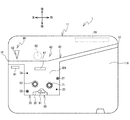
- 3 is a plan view of a main body case 11.
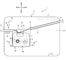
- FIG. It is a top view of the main body case 11 with which the tube 9 and the ribbon cassette 100 were mounted
- FIG. 4 is a cross-sectional view taken along the line AA in FIG. 3.
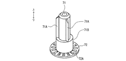
- 6 is a perspective view of a detection rotating shaft 71.
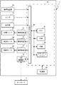
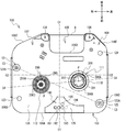
- FIG. FIG. 2 is a block diagram illustrating an electrical configuration of the printing apparatus 1. It is the perspective view which looked at the ribbon cassette 100 from the upper left rear. 2 is a plan view of the ribbon cassette 100.
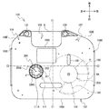
- FIG. 2 is a bottom view of the ribbon cassette 100.
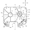
- FIG. 3 is a plan view of a lower case 103.
- FIG. 4 is a bottom view of the upper case 102.
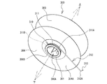
- FIG. It is the perspective view which looked at the winding spool 300 and the clutch spring 310 from the downward direction.
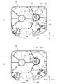
- 4 is a plan view of the lower case 103 when an external force F is applied to the ink ribbon 8.
- FIG. It is a bottom view of the upper case in a modification.
- the lower left, upper right, upper left, lower right, upper and lower in FIG. 1 are defined as the front, rear, left, right, upper, and lower sides of the printing apparatus 1, respectively.
- the upper right, lower left, lower right, upper left, upper and lower in FIG. 7 are defined as the front, rear, left, right, upper and lower of the ribbon cassette 100, respectively.
- the printing apparatus 1 is an apparatus that performs printing while conveying a tube 9 that is a cylindrical print medium, and cuts the tube 9 after printing.
- the printing apparatus 1 includes a housing 10 including a main body case 11 and a cover 12.
- the main body case 11 is a rectangular parallelepiped box-shaped member that is long in the left-right direction.
- the cover 12 is a plate-like member disposed on the upper side of the main body case 11.
- the rear end portion of the cover 12 is rotatably supported by the rear upper end portion of the main body case 11.
- the lock mechanism 13 is provided at the front upper end of the main body case 11.
- the lock mechanism 13 locks the front end portion of the cover 12 that is closed with respect to the main body case 11 to restrict the opening of the cover 12.
- the cover 12 When the cover 12 is closed with respect to the main body case 11 (see FIG. 1), the cover 12 covers the mounting surface 11A (see FIG. 2).
- the mounting surface 11 ⁇ / b> A is an upper surface of the main body case 11.
- the keyboard 7 is detachably mounted on the upper surface of the cover 12.
- the keyboard 7 includes an operation unit 7A having a plurality of keys and a display unit 7B for displaying a screen including various information.
- the user can edit the character to be printed on the tube 9 on the screen displayed on the display unit 7B by operating the operation unit 7A. Characters include letters, figures, symbols, and the like.
- a USB (Universal Serial Bus) cable 79 is connected to a board (not shown) in the keyboard 7. The USB cable 79 is drawn rightward from the right side surface of the keyboard 7.
- the operation unit 17 is a plurality of operation buttons including a power button and a start button provided on the front right side of the main body case 11.
- the tube insertion opening 15 is an opening provided in the upper part on the rear side of the right surface of the main body case 11 for guiding the tube 9 into the housing 10.
- the tube discharge port 16 is an opening provided in the upper part on the rear side of the left surface of the main body case 11 for discharging the tube 9 to the outside of the housing 10.
- the tube discharge port 16 is slightly in front of the tube insertion port 15.
- the mounting surface 11A is provided with a ribbon mounting portion 30, a tube mounting portion 40, and the like.
- the ribbon mounting part 30 is a part where the ribbon cassette 100 can be attached and detached.
- the ribbon mounting portion 30 is a recess that opens upward and is formed in an opening shape that is slightly larger than the ribbon cassette 100 in plan view.
- the rear part of the ribbon mounting part 30 communicates with a tube mounting part 40 described later in the front-rear direction.
- the ribbon mounting portion 30 of this example is provided on the left side of the mounting surface 11 ⁇ / b> A and on the front side of the tube mounting portion 40. The user mounts the ribbon cassette 100 on the ribbon mounting unit 30 from above so that the vertical and horizontal and front and rear directions of the ribbon cassette 100 coincide with the vertical and horizontal and front and rear directions of the printing apparatus 1.
- Positioning pins 31 and 32, support pins 33 and 34, and a support portion 35 are provided inside the ribbon mounting portion 30.
- the positioning pins 31 and 32 and the support pins 33 and 34 are all cylindrical shafts extending upward from the bottom surface 30 ⁇ / b> A of the ribbon mounting portion 30.
- the upper ends of the positioning pins 31 and 32 and the support pins 33 and 34 are all at the same vertical position (ie, height position).
- the positioning pins 31 and 32 have the same diameter.
- the support pins 33 and 34 have the same diameter as each other and a smaller diameter than the positioning pins 31 and 32.
- the positioning pins 31 and 32 are provided at positions corresponding to the positioning holes 121 and 122 (see FIG. 9) of the ribbon cassette 100 mounted on the ribbon mounting unit 30, respectively.
- the support pins 33 and 34 are provided at positions corresponding to the pin holes 123 and 124 (see FIG. 9) of the ribbon cassette 100 mounted on the ribbon mounting unit 30, respectively.
- the positioning pin 31 and the support pin 33 are respectively provided on the right rear side and the right front side of a later-described detection rotation shaft 71 and are arranged substantially in the front-rear direction.
- the positioning pin 32 and the support pin 34 are respectively provided on the left front side and the left rear side of a ribbon take-up shaft 63 which will be described later, and are aligned in the front-rear direction.
- the front-rear direction distance between the positioning pin 32 and the support pin 34 is slightly larger than the front-rear direction distance between the positioning pin 31 and the support pin 33.
- the support portion 35 is a stepped portion protruding upward from the bottom surface 30A.
- the upper end surface of the support portion 35 is at the same vertical position (ie, height position) as the upper end portions of the positioning pins 31 and 32 and the support pins 33 and 34.
- the support portion 35 is provided at a position corresponding to the front concave portion 125 (see FIG. 9) of the ribbon cassette 100 attached to the ribbon attachment portion 30.
- the support part 35 is provided on a line connecting the print head 61 and the front and rear direction and the positioning pin 32 and the support pin 33.
- the upper end surface of the support portion 35 is a flat surface corresponding to the front concave portion 125 in plan view.
- the tube mounting part 40 is a part where the tube 9 can be attached and detached.
- the tube mounting portion 40 is a groove portion that extends upward from the tube insertion port 15 to the vicinity of the right side of the tube discharge port 16 and opens upward. Since the tube discharge port 16 is slightly in front of the tube insertion port 15, the tube mounting portion 40 is slightly inclined to the left front side and extends in the substantially left-right direction. A direction in which the tube mounting portion 40 extends from the tube insertion port 15 toward the tube discharge port 16 is referred to as a tube conveyance direction. The user attaches the tube 9 to the tube attachment portion 40 along the tube conveyance direction so that the tube 9 extends from the tube insertion port 15 to the tube discharge port 16.
- the control board 19 is a board that controls the operation of the printing apparatus 1. As shown in FIG. 2, the control board 19 of this example is provided in the right rear part in the inside of the main body case 11, and connects with the USB connection part 18 (refer FIG. 6).
- the USB connection portion 18 is exposed to the outside of the main body case 11 from a plug housing portion 10A (see FIG. 1) formed at the lower right side of the housing 10 (see FIG. 1).
- a USB cable 79 (see FIG. 1) pulled out from the keyboard 7 is connected to the USB connection unit 18 via the plug housing unit 10A.
- the printing mechanism 60 includes a print head 61, a movable conveyance roller 62, a ribbon take-up shaft 63, a conveyance motor 64 (see FIG. 6), and the like.
- the print head 61 and the ribbon take-up shaft 63 are erected upward from the bottom surface 30A.
- the print head 61 and the ribbon take-up shaft 63 extend above the positioning pins 31 and 32, the support pins 33 and 34, and the support part 35.
- the print head 61 is a thermal head provided with a heating element (not shown).
- the print head 61 is provided at a position corresponding to the head insertion portion 109 (see FIG. 7) of the ribbon cassette 100 attached to the ribbon attachment portion 30.
- the print head 61 is provided in the approximate center of the rear part of the ribbon mounting part 30.
- the ribbon take-up shaft 63 is a shaft that can rotate together with a take-up spool 300 (see FIG. 4) of the ribbon cassette 100 described later.
- On the outer peripheral surface of the ribbon take-up shaft 63 there are provided a plurality of projecting pieces 63A that are arranged radially and equidistantly about the axis of the ribbon take-up shaft 63 (see FIG. 4).
- Each protruding piece 63 ⁇ / b> A protrudes radially outward from the outer peripheral surface of the ribbon winding shaft 63 and extends downward from the vicinity of the upper end portion of the ribbon winding shaft 63.
- the ribbon take-up shaft 63 is provided at a position corresponding to the first support hole 111 (see FIG. 7) of the ribbon cassette 100 attached to the ribbon attachment unit 30.
- the ribbon take-up shaft 63 is in front of the support pin 34 and behind the positioning pin 32 in the left part of the ribbon mounting portion 30.
- the movable conveyance roller 62 is a roller that can rotate relative to the print head 61.
- the movable conveyance roller 62 is disposed behind the ribbon mounting portion 30 and can be displaced between a retracted position and an operating position as the cover 12 (see FIG. 1) is opened and closed.
- the movable conveyance roller 62 is disposed behind the tube mounting portion 40 and is separated from the print head 61 (see FIG. 2).
- the movable conveyance roller 62 is in the operating position, a part of the movable conveyance roller 62 is disposed inside the tube mounting portion 40 and is close to the print head 61 (see FIG. 3).
- the conveyance motor 64 is a motor that rotationally drives the movable conveyance roller 62 and the ribbon take-up shaft 63.
- a disk-shaped gear 65 that can rotate around the ribbon take-up shaft 63 is provided in the vicinity of the lower end of the ribbon take-up shaft 63.
- the gear 65 is connected to a fixing member 67 fixed around the ribbon take-up shaft 63 via a one-way clutch 66.
- the one-way clutch 66 stably rotates the ribbon take-up shaft 63 by the elastic force of the clutch spring, and the ribbon take-up shaft 63 has a predetermined take-up direction (in this example, a counterclockwise direction in plan view). Restricts rotation in the opposite direction (hereinafter referred to as the reverse direction).
- the transport motor 64 rotates the ribbon winding shaft 63 in the winding direction via the one-way clutch 66 and the fixing member 67 by rotating the gear 65 counterclockwise in plan view.
- the movable transport roller 62 (see FIG. 2) rotates in a clockwise direction in a plan view via a gear group (not shown) interlocked with the gear 65.
- the movable conveyance roller 62 and the ribbon take-up shaft 63 rotate in synchronization.
- the transport amount detection unit 70 is a member for detecting the transport amount of the ink ribbon 8 during the printing operation.
- the carry amount detection unit 70 includes a detection rotating shaft 71, a detection plate 72, and a sensor 73.
- the detection rotating shaft 71 is erected upward from the bottom surface 30A (see FIG. 2).
- the detection rotating shaft 71 extends to a position higher than the positioning pins 31 and 32, the support pins 33 and 34, and the support portion 35.
- the upper end portion of the detection rotating shaft 71 is below the upper end portions of the print head 61 and the ribbon take-up shaft 63.
- the detection rotating shaft 71 is a shaft that can rotate together with a ribbon spool 200 of the ribbon cassette 100 described later.
- the detection rotary shaft 71 is provided at a position corresponding to the second support hole 112 (see FIG. 9) of the ribbon cassette 100 mounted on the ribbon mounting portion 30.
- the detection rotating shaft 71 is on the front side of the positioning pin 31 and on the rear side of the support pin 33 in the right part of the ribbon mounting portion 30.
- the axis of the detection rotating shaft 71 is slightly in front of the axis of the ribbon take-up shaft 63.
- the detection rotating shaft 71 has a plurality of protruding pieces 71 ⁇ / b> A, a cylindrical portion 71 ⁇ / b> B, and a detection plate 72.
- the cylindrical portion 71 ⁇ / b> B is a cylindrical member that is provided around the detection rotation shaft 71 and that can rotate together with the detection rotation shaft 71.
- the plurality of projecting pieces 71A are provided on the outer peripheral surface of the cylindrical portion 71B, and are arranged radially and at equal intervals around the axis of the rotation shaft 71 for detection.
- Each protruding piece 71A protrudes radially outward from the outer peripheral surface of the cylindrical portion 71B and extends downward from the vicinity of the upper end portion of the cylindrical portion 71B.
- the detection plate 72 has a disk shape that protrudes radially outward from the vicinity of the lower end of the cylindrical portion 71B.
- the plan view center of the detection plate 72 coincides with the axis of the detection rotation shaft 71.
- the detection plate 72 is provided with a plurality of detection holes 72A.
- the plurality of detection holes 72A are holes that pass through the detection plate 72 in the vertical direction and are arranged radially and at equal intervals around the center of the detection plate 72 in plan view.
- the sensor 73 is a transmissive photosensor having a light emitting part 73A and a light receiving part 73B.
- the light emitting unit 73A and the light receiving unit 73B are disposed opposite to each other on both the upper and lower sides with the detection plate 72 interposed therebetween.
- the CPU 41 (see FIG. 6) irradiates light from the light emitting unit 73A toward the light receiving unit 73B during the printing operation.
- the light emitted from the light emitting unit 73A passes through any of the plurality of detection holes 72A and is received by the light receiving unit 73B.
- the sensor 73 outputs an ON signal to the CPU 41.
- the sensor 73 outputs an OFF signal to the CPU 41.
- the sensor 73 may be a reflective photosensor that can detect the light reflected by the detection plate 72.
- the index detection unit 80 is a member for detecting the type index unit 190 (see FIG. 9) of the ribbon cassette 100.
- the index detection unit 80 includes five detection switches 81 provided on a substrate (not shown).
- Each detection switch 81 is a mechanical switch that can advance and retreat in the vertical direction.
- Each of the five detection switches 81 is movable in the vertical direction through a hole formed in the upper end surface of the support portion 35.
- the five detection switches 81 are provided at positions respectively corresponding to the indicator portions 191 to 195 (see FIG. 9) of the ribbon cassette 100 attached to the ribbon attachment portion 30.
- four detection switches 81 are arranged side by side in the left-right direction. Among the four detection switches 81, the remaining one detection switch 81 is arranged behind the second detection switch 81 from the left.
- Each detection switch 81 is biased upward by a spring (not shown).
- the detection switch 81 to which no external force is applied is located at a reference position moved upward from the support portion 35 by a biasing force of a spring (not shown).
- the index detection unit 80 outputs an OFF signal corresponding to the detection switch 81 at the reference position to a CPU 41 (see FIG. 6) described later.
- the detection switch 81 is pressed from above, it moves to a pressed position below the reference position.
- the index detection unit 80 outputs an ON signal corresponding to the detection switch 81 at the pressed position to the CPU 41.
- a combination of the ON signal and the OFF signal of the five detection switches 81 is referred to as a type detection pattern.
- the cutting mechanism 90 is a mechanism that executes a cutting operation of the tube 9. As shown in FIG. 2, the cutting mechanism 90 is provided in the vicinity of the left end portion of the tube mounting portion 40 in the main body case 11. That is, the cutting mechanism 90 is on the downstream side of the print head 61 in the tube conveyance direction.
- the cutting mechanism 90 includes a cradle 91, a cutting blade 92, and a cutting motor 93 (see FIG. 6).
- the cradle 91 is provided in front of the left end portion of the tube mounting portion 40 and has a rectangular parallelepiped shape.
- the cutting blade 92 faces the cradle 91 from behind with the tube mounting portion 40 interposed therebetween.
- the cutting motor 93 moves the cutting blade 92 in the front-rear direction so that the cutting blade 92 approaches or separates from the cradle 91.
- the control board 19 includes a CPU 41, a ROM 42, a RAM 44, a flash memory 45, an input / output interface 49, and the like, which are connected via a data bus.
- the ROM 42 stores a program for the CPU 41 to execute various controls including a printing operation.
- the RAM 44 temporarily stores various data.
- the flash memory 45 stores a table that defines ribbon types corresponding to the type detection patterns. For example, the ribbon type is the color and width of the ink ribbon 8 accommodated in the ribbon cassette 100.
- the printing apparatus 1 has a power supply unit 48.
- the power supply unit 48 is connected to a battery (not shown) mounted in the main body case 11 or connected to an external power supply (not shown) via a cord, and supplies power to the control board 19.
- the operation unit 17, the USB connection unit 18, the drive circuits 51 to 53, the sensor 73, and the index detection unit 80 are connected to the input / output interface 49, respectively.
- the USB connection unit 18 is connected to the keyboard 7 via the USB cable 79 (see FIG. 1).
- the CPU 41 receives various types of information input via the operation unit 17.
- the CPU 41 receives various instructions input via the operation unit 7A (see FIG. 1) and controls display of the screen of the display unit 7B.
- the CPU 41 receives the ON / OFF signal output from the sensor 73 and the type detection pattern output from the index detection unit 80.
- the drive circuits 51 to 53 are connected to the print head 61, the transport motor 64, and the cutting motor 93, respectively.
- the CPU 41 drives and controls the print head 61 by transmitting a control signal to the drive circuit 51.
- the CPU 41 drives and controls the conveyance motor 64 by transmitting a pulse signal to the drive circuit 52.
- the CPU 41 controls the cutting motor 93 by transmitting a control signal to the driving circuit 53.
- the ribbon cassette 100 will be described with reference to FIGS. 7 to 10 illustrate the ribbon cassette 100 in an initial state that is not used for the printing operation. In the ribbon cassette 100 in the initial state, all the ink ribbons 8 are unused. A predetermined upper limit amount of the ink ribbon 8 is wound around the ribbon spool 200. The ink ribbon 8 is not wound on the take-up spool 300 (the same applies to FIG. 4 described above).
- the ribbon cassette 100 has a case 101 for accommodating the ink ribbon 8.
- the shape of the case 101 is a box shape that is long in the left-right direction and short in the up-down direction.
- the case 101 includes a lower case 103 and an upper case 102 assembled on the upper side of the lower case 103.
- the upper surface of the upper case 102 and the lower surface of the lower case 103 are the upper surface 104 and the lower surface 105 of the case 101, respectively.
- the upper surface 104 and the lower surface 105 face each other in the vertical direction and have substantially the same shape in plan view.
- a virtual line extending in the front-rear direction through the center in the left-right direction of the case 101 is a center line C1.
- a virtual line extending in the left-right direction through the center in the front-rear direction of the case 101 is a center line C2.
- the side surface 106 of the case 101 connects the upper surface 104 and the lower surface 105 in the vertical direction, and extends along outer edges of the upper surface 104 and the lower surface 105.
- the side surface 106 includes a front surface 106A, a right surface 106B, a left surface 106C, a head circumferential surface 106D, and connection surfaces 106E and 106F.
- the front surface 106A extends in the left-right direction.
- the right surface 106B and the left surface 106C extend rearward in parallel from the right end and the left end of the front surface 106A, respectively.
- the right surface 106B and the left surface 106C are arranged side by side in the left-right direction, and the lengths in the front-rear direction are substantially equal.
- the head circumferential surface 106D is a portion of the side surface 106 that is provided across the center line C1 in a plan view and is recessed forward from the rear end side of the case 101.
- the connection surface 106E extends rightward and forward from the right rear end portion of the head peripheral surface 106D, and is connected to the rear end portion of the right surface 106B.
- the connection surface 106F extends leftward from the left rear end portion of the head peripheral surface 106D, and is connected to the rear end portion of the left surface 106C.
- the length in the extending direction of the connecting surface 106E is larger than the length in the extending direction of the connecting surface 106F.
- the inner region surrounded by the head peripheral surface 106D is a head insertion portion 109.
- the head insertion portion 109 penetrates the case 101 in the vertical direction and opens to the rear of the case 101.
- the head insertion portion 109 has a substantially rectangular shape that is long in the left-right direction in plan view, and extends in the left-right direction across the center line C1.
- the center of the head insertion portion 109 in the left-right direction is slightly to the left of the center line C1.
- the part on the right side of the head insertion portion 109 in the case 101 is a first guide portion 107.
- the first guide portion 107 has a triangular shape in plan view surrounded by the right surface of the head circumferential surface 106D and the connection surface 106E.
- a ribbon outlet 107 ⁇ / b> A that is an opening communicating with the head insertion portion 109 is provided at the left rear end portion of the first guide portion 107.
- the ink ribbon 8 is conveyed from the inside of the case 101 to the outside through the ribbon outlet 107A.
- a portion of the case 101 on the left side of the head insertion portion 109 is a second guide portion 108.
- the second guide portion 108 has a triangular shape in plan view, surrounded by the left surface of the head circumferential surface 106D and the connection surface 106F.
- a ribbon inlet 108 ⁇ / b> A that is an opening communicating with the head insertion portion 109 is provided at the right rear end portion of the second guide portion 108.
- the ink ribbon 8 is conveyed from the outside of the case 101 to the inside through the ribbon inlet 108A. That is, a part of the ink ribbon 8 is exposed from the case 101 between the ribbon outlet 107A and the ribbon inlet 108A.
- the case 101 is provided with a first support hole 111 that rotatably supports the take-up spool 300 and a second support hole 112 (see FIG. 9) that rotatably supports the ribbon spool 200.
- the first support hole 111 is provided in the left part of the case 101, and is in front of the second guide part 108 and in the rear of a later-described front concave part 125.
- the first support hole 111 includes an upper hole 111A (see FIG. 8) that is a circular hole penetrating the upper case 102 in the vertical direction, and a lower hole 111B (see FIG. 9) that is a circular hole penetrating the lower case 103 in the vertical direction. ).
- the upper hole 111A and the lower hole 111B are holes having the same diameter arranged in the vertical direction.
- a rotation axis passing through the rotation center of the take-up spool 300 supported by the first support hole 111 is referred to as an axis J.
- the second support hole 112 is provided in the right part of the case 101 and is located in front of the first guide part 107 and in the rear part of the front concave part 125.
- the second support hole 112 is a circular hole that penetrates the lower case 103 in the vertical direction.
- a rotation axis passing through the rotation center of the ribbon spool 200 supported by the second support hole 112 is referred to as an axis P.
- the axes P and J are in front of the center line C2.
- the axis P is ahead of the axis J.
- the lower case 103 is provided with positioning holes 121, 122, pin holes 123, 124, and a front recess 125.
- the positioning holes 121 and 122 and the pin holes 123 and 124 are all concave portions that are recessed upward from the lower surface 105.
- the upper ends of the positioning holes 121 and 122 and the pin holes 123 and 124 are at height reference positions that are predetermined vertical positions in the case 101.
- the height reference position is a specified distance below the center of the case 101 in the vertical direction. The specified distance is constant regardless of the vertical length of the case 101 (that is, the thickness of the case 101).
- the positioning hole 121 and the pin hole 123 are provided on the right rear side and the right front side of the second support hole 112, respectively, and are aligned in the front-rear direction.
- the positioning hole 121 and the pin hole 123 are both in the vicinity of the right surface 106B.
- the positioning hole 122 and the pin hole 124 are provided on the left front side and the left rear side of the lower hole 111B, respectively, and are arranged substantially in the front-rear direction.
- the positioning hole 122 and the pin hole 124 are both in the vicinity of the left surface 106C.
- the positioning hole 122 and the pin hole 123 are behind the center line C2.
- the positioning hole 121 and the pin hole 124 are behind the center line C2.
- the distance in the front-rear direction of the positioning hole 122 and the pin hole 124 is larger than the distance in the front-rear direction of the positioning hole 121 and the pin hole 123.
- the lower portion of the positioning hole 121 has a circular opening shape.
- the opening width of the lower portion of the positioning hole 121 is slightly larger than the shaft diameter of the positioning pin 31 (see FIG. 2).
- the locking portion 121A which is the upper portion of the positioning hole 121, is a round hole that opens downward and is closed by a top surface (not shown) at the height reference position.
- the opening width of the locking portion 121 ⁇ / b> A is smaller than the lower portion of the positioning hole 121 and is the same diameter as the shaft diameter of the positioning pin 31.
- the lower part of the positioning hole 122 has a circular opening shape like the lower part of the positioning hole 121.
- the opening width of the lower portion of the positioning hole 122 is slightly larger than the shaft diameter of the positioning pin 32 (see FIG. 2).
- the locking portion 122A which is the upper portion of the positioning hole 122, is a hole that opens downward and is closed by a top surface (not shown) at the height reference position.
- the locking portion 122A is a long hole extending in the right rear direction and the left front direction.
- the minimum opening width of the locking portion 122A (that is, the length in the short direction of the locking portion 122A) is the same as the shaft diameter of the positioning pin 32.
- the locking portion 121A is disposed on the extended line in the longitudinal direction of the locking portion 122A.
- a virtual straight line connecting the centers of the locking portions 121A and 122A is a connecting line C3.
- the connecting line C3 extends substantially parallel to the longitudinal direction of the locking portion 122A.
- the axis J is on the left side of the connecting line C3.
- the axis P is on the right side of the connecting line C3.
- the pin holes 123 and 124 are round holes that are open downward and are closed by a top surface (not shown) whose upper end is at the height reference position.
- the opening widths of the pin holes 123 and 124 are slightly larger than the shaft diameters of the support pins 33 and 34, respectively.
- the opening widths of the pin holes 123 and 124 have the same diameter and are smaller than the opening widths of the lower portions of the positioning holes 121 and 122.
- the front recessed portion 125 is a stepped portion that is recessed upward from the lower surface 105.
- the upper end surface of the front recess 125 is at the height reference position.
- the front concave portion 125 of this example is located on the line connecting the head insertion portion 109 and the position aligned in the front-rear direction and the positioning hole 122 and the pin hole 123.
- the front recess 125 is provided at the front end of the lower case 103 and extends in the left-right direction across the center line C1.
- the left end portion of the front concave portion 125 is at a position substantially equal to the left end portion of the head insertion portion 109 in the left-right direction.
- the right end portion of the front recess 125 is slightly to the right of the right end portion of the head insertion portion 109 in the left-right direction.
- the center in the left-right direction of the front recess 125 is slightly to the left of the center line C1.
- the front recess 125 extends rearward along the center line C1 when viewed from the bottom.
- the rear end portion of the front concave portion 125 is substantially at the same position as the pin hole 123 in the front-rear direction.
- a type indicator 190 indicating the ribbon type is provided on the upper end surface of the front recess 125.
- An imaginary straight line connecting the axes J and P is a connecting line C4.
- the type indicator 190 is on the front side of the connecting line C4 and is aligned with the head circumferential surface 106D in the front-rear direction.
- the type indicator portion 190 of this example includes five indicator portions 191 to 195.
- the indicator portions 191 to 194 are arranged in the left-right direction along the front surface 106A.
- the index unit 195 is disposed behind the second index unit 193 from the left among the index units 191 to 194.
- Each of the indicator portions 191 to 195 has a pattern corresponding to the ribbon type of the ribbon cassette 100, and is configured with either a surface portion or a hole portion.
- the indicator portions 191 to 193 and 195 are holes, and the indicator portion 194 is a surface portion.
- the ink ribbon 8 is accommodated in the case 101 in a posture in which the width direction (short direction) is substantially parallel to the vertical direction.
- a ribbon spool 200 and a take-up spool 300 are provided inside the case 101.
- the ink ribbon 8 is transported from the ribbon spool 200 to the take-up spool 300 via a predetermined transport path (hereinafter referred to as a ribbon transport path) in a posture in which the width direction is substantially parallel to the vertical direction.
- the direction in which the ink ribbon 8 is transported along the ribbon transport path is referred to as the ribbon transport direction.
- the ribbon spool 200 is a cylindrical member extending in the vertical direction, and is wound around one end side in the longitudinal direction of the ink ribbon 8 (that is, the upstream side in the ribbon transport direction).
- the take-up spool 300 is a cylindrical member extending in the vertical direction, and is connected to the other end side in the longitudinal direction of the ink ribbon 8 (that is, the downstream side in the ribbon transport direction).
- a mounting hole 200A penetrating in the vertical direction is provided.
- the outer peripheral surface of the ribbon spool 200 is a supply surface 200B around which the unused ink ribbon 8 is wound.
- the unused ink ribbon 8 is wound around the supply surface 200B so that the ink surface to which the ink is applied is the inside of both surfaces of the ink ribbon 8.
- the upper limit amount of the ink ribbon 8 can be wound around the supply surface 200B.
- the ink ribbon 8 wound around the supply surface 200B is referred to as a first ribbon roll 8A.
- the outer diameter of the first ribbon roll 8A becomes the maximum value when the upper limit amount of the ink ribbon 8 is wound around the supply surface 200B.
- the upper limit amount of the ink ribbon 8 wound around the ribbon spool 200 is referred to as a maximum diameter first ribbon roll 8A.
- the upper and lower ends of the ribbon spool 200 are provided with protrusions 200C and 200D, respectively.
- the protruding portion 200C protrudes above the supply surface 200B.
- the protrusion 200D protrudes downward from the supply surface 200B.
- the inner surface 102A of the upper case 102 is provided with a support portion 140 that faces the second support hole 112 in the vertical direction (see FIG. 11).
- the protruding portion 200 ⁇ / b> C is attached to the support portion 140 from below and is rotatably supported by the support portion 140.
- the protruding portion 200 ⁇ / b> D is fitted into the second support hole 112 from above and is rotatably supported by the second support hole 112. That is, the ribbon spool 200 is rotatably supported by the second support hole 112 and the support part 140. Accordingly, the axis P substantially coincides with the center of the second support hole 112 in plan view.
- a cylindrical rotating member 290 around which a clutch spring 280 is wound is mounted on the mounting hole 200A. An end portion of the clutch spring 280 is locked to the support portion 140.
- the rotating member 290 can rotate together with the ribbon spool 200.
- the clutch spring 280 is expanded in diameter, and therefore the ribbon spool is interposed via the rotating member 290.
- the rotational load applied to 200 is relatively small.
- the rotational load is a load that acts to prevent the rotation of the member.
- the rotational load applies a rotational torque to the ribbon spool 200. The rotational torque does not change depending on the outer diameter of the first ribbon roll 8A and is stably generated.
- the clutch spring 280 is reduced in diameter, so that the rotational load applied to the ribbon spool 200 via the rotating member 290 is reduced. Is relatively large. That is, the rotating member 290 stably rotates the ribbon spool 200 in the pull-out direction by the elastic force of the clutch spring 280 and restricts the ribbon spool 200 from rotating in the direction opposite to the pull-out direction.
- the take-up spool 300 includes a main body 301, a plurality of engaging protrusions 302, an upper support plate 303, a lower support plate 304, and the like.
- the main body 301 is a cylindrical body extending in the vertical direction.
- a mounting hole 300 ⁇ / b> A penetrating in the vertical direction is provided inside the main body 301.
- Each of the plurality of engagement protrusions 302 protrudes from the inner peripheral surface of the main body 301 toward the axis J.
- the plurality of engaging protrusions 302 are arranged radially and equidistantly about the axis J.
- the outer peripheral surface of the main body 301 is a winding surface 300B on which the used ink ribbon 8 is wound.
- the used ink ribbon 8 is wound around the winding surface 300B along the winding direction (the direction of the arrow R1) so that the ink surface of both surfaces of the ink ribbon 8 is outside.
- the upper limit amount of the ink ribbon 8 can be wound around the winding surface 300B.
- the ink ribbon 8 wound around the winding surface 300B is referred to as a second ribbon roll 8B (see FIG. 3).
- the outer diameter of the second ribbon roll 8B becomes the maximum value when the upper limit amount of the ink ribbon 8 is wound around the winding surface 300B.
- the upper limit amount of the ink ribbon 8 wound around the take-up spool 300 is referred to as a maximum diameter second ribbon roll 8B.
- the upper support plate 303 has a disk shape extending radially outward from the vicinity of the upper end of the main body 301.
- the lower support plate 304 has a disk shape extending radially outward from the vicinity of the lower end of the main body 301.
- the upper support plate 303 and the lower support plate 304 are plate-like members having the same diameter and arranged to face each other in the vertical direction.
- the vertical distance between the upper support plate 303 and the lower support plate 304 is slightly larger than the length in the width direction of the ink ribbon 8. Accordingly, the second ribbon roll 8B is held between the upper support plate 303 and the lower support plate 304.
- a region surrounded by the upper support plate 303, the lower support plate 304, and the winding surface 300B is a storage portion 305 that can store the second ribbon roll 8B.
- the outer diameter of the accommodating portion 305 (that is, the outer diameter of each of the upper support plate 303 and the lower support plate 304) is larger than the outer diameter of the second ribbon roll 8B having the maximum diameter.
- the upper support plate 303 is above the supply surface 200B.
- the lower support plate 304 is below the supply surface 200B.
- the right end portions of the upper support plate 303 and the lower support plate 304 are between the center line C1 and the ribbon spool 200. That is, the accommodating part 305 is close to the supply surface 200B from the left side.
- a part of the first ribbon roll 8A enters the housing portion 305 from the right side. In other words, when the radius of the first ribbon roll 8A exceeds the distance from the axis P to the storage unit 305, a part of the first ribbon roll 8A is disposed in the storage unit 305.
- the case 101 can be further downsized.
- the outer diameter of the second ribbon roll 8B increases and the outer diameter of the first ribbon roll 8A decreases. Therefore, the first ribbon roll 8A and the second ribbon roll 8B can be prevented from interfering with each other.
- Projection portions 300C and 300D are provided on the upper end portion and the lower end portion of the take-up spool 300, respectively.
- the protruding portion 300C protrudes above the upper support plate 303.
- the protrusion 300D protrudes below the lower support plate 304.
- the protrusion 300C is fitted into the upper hole 111A from below and is rotatably supported by the upper hole 111A.
- the protrusion 300D is fitted into the lower hole 111B from above and is rotatably supported by the lower hole 111B. That is, the take-up spool 300 is rotatably supported by the first support hole 111. Therefore, the axis J substantially coincides with the center of the first support hole 111 in plan view.
- a metal clutch spring 310 is provided below the lower support plate 304.
- the clutch spring 310 is a spring member for returning the slackened ink ribbon 8 to a state where an appropriate tension is applied.
- the clutch spring 310 includes a coiled winding portion 311 and an extending portion 312 extending from the upper end portion 311A of the winding portion 311.
- the winding portion 311 extends from the upper end portion 311A of the winding portion 311 to the lower end portion 311B of the winding portion 311 in the direction opposite to the winding direction (that is, the reverse direction, the direction of the arrow R2) and protrudes.
- a plurality of turns (three turns in this example) are wound around the outer peripheral surface of the portion 300D.
- the upper end 311A is in contact with the lower surface 304A of the lower support plate 304.
- the lower end 311B is located below the upper end 311A (that is, in a direction away from the lower support plate 304).
- the extending portion 312 is straight from the upper end portion 311A in the tangential direction along the lower support plate 304 to the vicinity of the head peripheral surface 106D (that is, a position farther from the axis J than the engaging portion 150 described later in plan view). It extends in a shape. A portion of the extended portion 312 that is on the inner side of the outer diameter edge of the lower support plate 304 from the upper end portion 311A is in contact with the lower surface 304A. The vicinity of the distal end portion 312 ⁇ / b> A of the extending portion 312 is engaged with an engaging portion 150 described later provided on the case 101.
- the extending portion 312 has a locking portion 313 that extends in the direction opposite to the axis J from the tip portion 312A to the upper end portion 311A.
- the locking portion 313 suppresses the clutch spring 310 from being detached in the extending direction of the extending portion 312 from an engaging portion 150 described later.
- the winding portion 311 When the take-up spool 300 rotates in the take-up direction (arrow R1 direction), the winding portion 311 is expanded in diameter, so that the rotational load applied to the take-up spool 300 is relatively small.
- the winding spool 300 rotates in the reverse rotation direction the winding portion 311 is reduced in diameter, so that the rotational load applied to the winding spool 300 is relatively large. That is, the clutch spring 310 stably rotates the take-up spool 300 in the take-up direction by elastic force and restricts the take-up spool 300 from rotating in the reverse direction.
- an engagement portion 150 and a plurality of bent portions 131 to 137 are provided inside the case 101.
- the engaging portion 150 is a member for restricting movement of the clutch spring 310 in the winding direction and the reverse direction.
- the engaging portion 150 is provided in the vicinity of the center line C1 and the head circumferential surface 106D in plan view. That is, the engaging portion 150 is provided between the axis J and the axis P and behind the connecting line C4 in plan view.
- the distance from the upper end portion 311A to the engaging portion 150 is smaller than the length from the upper end portion 311A to the distal end portion 312A and larger than the distance from the distal end portion 312A to the engaging portion 150.
- the engaging portion 150 is provided at a position near the tip portion 312A among the upper end portion 311A and the tip portion 312A in plan view.
- the distance from the axis P to the engaging portion 150 is larger than the radius of the first ribbon roll 8A having the maximum diameter. That is, the engaging portion 150 is provided at a position farther from the axis P than the outermost periphery of the first ribbon roll 8A having the maximum diameter in plan view.
- the distance from the axis J to the engaging part 150 is larger than the radius of the second ribbon roll 8B having the maximum diameter. That is, the engaging portion 150 is provided at a position farther from the axis J than the outermost circumference of the second ribbon roll 8B having the maximum diameter in plan view.
- the engaging part 150 has a first engaging part 151 and a second engaging part 152.
- the first engaging portion 151 is erected on the inner surface 103A of the lower case 103 in the vicinity of the head circumferential surface 106D and slightly to the left of the center line C1.
- the first engagement portion 151 is a plate-like member that extends to the right front and upward.
- the second engaging portion 152 is erected on the inner surface 103A at a position slightly separated from the first engaging portion 151 to the right front.
- the second engaging portion 152 is a plate-like member that extends to the front right and upward.
- the first engaging portion 151 and the second engaging portion 152 face each other with the extending portion 312 interposed therebetween.
- the mutually opposing surfaces in the first engaging portion 151 and the second engaging portion 152 are referred to as a first opposing surface 151A and a second opposing surface 152A, respectively.
- the first engaging portion 151 regulates the movement of the extending portion 312 in the winding direction when the extending portion 312 contacts the first facing surface 151A.
- the second engaging portion 152 regulates the movement of the extending portion 312 in the reverse rotation direction when the extending portion 312 contacts the second facing surface 152A.
- the bent portions 131 to 137 are members for setting the ribbon conveyance path and are members for meandering the ribbon conveyance path. Each of the bent portions 131 to 137 is erected on the inner surface 103A and extends upward to the upper case 102.
- the bent portions 131, 132, and 136 are cylindrical bodies fixed to the lower case 103. Specifically, the bent portions 131, 132, and 136 are formed integrally with the lower case 103.
- the bent portions 133 to 135, 137 are cylindrical rotating bodies that can rotate around an axis extending in the vertical direction.
- the bent portions 131 to 134 are provided at the right rear portion of the case 101.
- the bent portion 131 is on the right rear side of the second support hole 112 (see FIG. 9) in plan view.
- the positioning hole 121 is between the bent portion 131 and the ribbon spool 200 in the front-rear direction.
- the bent portion 131 is between the positioning hole 121 and the ribbon spool 200 in the left-right direction.
- the bent portion 131 is between the head peripheral surface 106D and the ribbon spool 200 in the front-rear direction.
- the distance from the axis P to the bent portion 131 is larger than the radius of the first ribbon roll 8A having the maximum diameter.
- the bent portions 132 to 134 are in the first guide portion 107.
- the bent portion 132 is on the left rear side of the bent portion 131.
- the bent portion 133 is on the left side of the bent portion 132.
- the bent portion 134 is on the left rear side of the bent portion 133 and is on the left rear portion of the first guide portion 107.
- the bent portions 135 to 137 are provided at the left rear portion of the case 101.
- the bent portions 135 to 137 are in the second guide portion.
- the bent portion 137 is on the left rear side of the first support hole 111 (see FIG. 8).
- the distance from the axis J to the bent portion 137 is larger than the radius of the maximum diameter second ribbon roll 8B (see FIG. 3).
- the bent portion 136 is on the left rear side of the bent portion 137.
- the bent portion 135 is on the right rear side of the bent portion 136 and on the right rear portion of the second guide portion 108.
- a window portion 160 and at least one elastic body 180 are provided around the support portion 140 in the upper case 102.
- the window portion 160 is a long hole that penetrates the upper case 102 in the vertical direction and extends in the radial direction with the support portion 140 as the center.
- the window portion 160 of this example extends rearward from the rear side of the support portion 140.
- the rear end portion of the window portion 160 is outside the first ribbon roll 8A having the maximum diameter in plan view. The user can recognize the remaining amount of the unused ink ribbon 8 by viewing the outer diameter position of the first ribbon roll 8 ⁇ / b> A through the window portion 160.
- Each elastic body 180 is a plate-like sponge provided on the inner surface 102A. Each elastic body 180 extends in the radial direction around the support portion 140. Each elastic body 180 extends from the outer edge of the support portion 140 to the outside of the maximum diameter first ribbon roll 8A in plan view. As shown in FIG. 4, each elastic body 180 is in elastic contact with the first ribbon roll 8 ⁇ / b> A from above inside the case 101. That is, each elastic body 180 is in surface contact over the entire radial direction on the upper surface of the first ribbon roll 8A, and biases the first ribbon roll 8A downward. In this example, two elastic bodies 180 are disposed on the front side and the right rear side of the support part 140.
- Each elastic body 180 is the same plate-like sponge having a fan shape with a thickness of 4 mm, and is attached to the inner surface 102A by a double-sided tape not shown. With each elastic body 180 in elastic contact with the first ribbon roll 8A, the thickness of each elastic body 180 is about 2 mm.
- the detection rotating shaft 71 is inserted into the mounting hole 200 ⁇ / b> A of the ribbon spool 200 through the second support hole 112.
- the plurality of protruding pieces 71A are engaged with the ribbon spool 200 in the mounting hole 200A, similarly to the plurality of protruding pieces 63A.
- the ribbon cassette 100 mounted on the ribbon mounting unit 30 is positioned at an appropriate position in the ribbon mounting unit 30 as follows.
- the positioning pins 31 and 32 and the support pins 33 and 34 are inserted into the positioning holes 121 and 122 and the pin holes 123 and 124, respectively.
- the upper end portion of the support pin 33 contacts the top surface of the pin hole 123 to position the ribbon cassette 100 in the vertical direction.
- the upper end portion of the support pin 34 contacts the top surface of the pin hole 124 to position the ribbon cassette 100 in the vertical direction.
- the upper end portion of the positioning pin 31 is closely fitted into the locking portion 121A to position the ribbon cassette 100 in the up, down, left, right, front and rear directions.
- the upper end portion of the positioning pin 32 is closely fitted into the locking portion 122 ⁇ / b> A to position each direction of the ribbon cassette 100 in the vertical and horizontal directions.
- the support portion 35 supports the front concave portion 125 from below and positions the ribbon cassette 100 in the vertical direction.
- each of the indicator portions 191 to 195 faces one of the five detection switches 81.
- Each detection switch 81 facing the index portions 191 to 193 and 195 is inserted into the hole and held at the reference position.
- the detection switch 81 facing the indicator portion 194 is pressed by the surface portion and displaced to the pressed position.
- the index detection unit 80 outputs a combination of an OFF signal corresponding to each detection switch 81 at the reference position and an ON signal corresponding to the detection switch 81 at the pressed position to the CPU 41 (see FIG. 6) as a type detection pattern.
- the CPU 41 specifies the ribbon type corresponding to the received type detection pattern with reference to the table of the flash memory 45 (see FIG. 6). Thereby, the printing apparatus 1 can specify the ribbon type of the ribbon cassette 100 mounted on the ribbon mounting unit 30.
- the cover 12 is closed in a state where the ribbon cassette 100 is mounted on the ribbon mounting portion 30 and the tube 9 is mounted on the tube mounting portion 40.
- the movable conveyance roller 62 is displaced to the operating position.
- the movable conveyance roller 62 urges the tube 9 in the tube mounting portion 40 and the unused ink ribbon 8 to overlap the print head 61.
- the tube 9 is elastically deformed by the urging force of the movable conveyance roller 62 and comes into surface contact with the print head 61 via the ink ribbon 8.
- the CPU 41 drives the transport motor 64 to rotate the movable transport roller 62 and the ribbon take-up shaft 63.
- the tube 9 in the tube mounting portion 40 is transported downstream in the tube transport direction as the movable transport roller 62 rotates. At this time, the tube 9 before printing outside the housing 10 is drawn into the tube mounting portion 40 through the tube insertion port 15.
- the take-up spool 300 rotates in the take-up direction (arrow R1 direction). In this case, the winding part 311 is expanded in diameter.
- the take-up spool 300 rotates, the ribbon spool 200 rotates in the drawing direction (arrow R3 direction). As a result, the ink ribbon 8 is pulled out from the vicinity of the rear end of the first ribbon roll 8A and conveyed along the following ribbon conveyance path.
- a relatively small rotational load is applied to the ribbon spool 200 by the elastic force of the clutch spring 280. As a result, an appropriate tension is applied to the conveyed ink ribbon 8, so that the ink ribbon 8 does not loosen easily.
- the unused ink ribbon 8 After the unused ink ribbon 8 is pulled out from the first ribbon roll 8A, the right front surface side of the bent portion 131, the right rear surface side of the bent portion 132, the left front surface side of the bent portion 133, and the right rear surface side of the bent portion 134 Go through in order.
- the unused ink ribbon 8 is discharged from the ribbon outlet 107 ⁇ / b> A to the outside of the case 101 and proceeds leftward in the head insertion portion 109. At this time, the unused ink ribbon 8 passes between the tube 9 and the print head 61.
- the CPU 41 drives the print head 61 to heat the ink ribbon 8 passing between the tube 9 and the print head 61 to print the character on the tube 9.
- the print head 61 of this example prints a normal image of the character on the front part of the tube 9 passing through the rear side.
- the CPU 41 drives the cutting motor 93 to bring the cutting blade 92 closer to the cradle 91, thereby cutting the printed tube 9.
- the cut tube 9 is discharged to the outside of the housing 10 through the tube discharge port 16.
- the used ink ribbon 8 enters the inside of the case 101 from the ribbon inlet 108A and passes through the left rear surface side of the bent portion 135, the left surface side of the bent portion 136, and the right rear surface side of the bent portion 137. Finally, the used ink ribbon 8 is taken up from the left side of the take-up spool 300 and held as the second ribbon roll 8B. As described above, the ink ribbon 8 is conveyed along the meandering ribbon conveyance path by passing through the plurality of bent portions 131 to 137. In this case, sliding friction occurs between the conveyed ink ribbon 8 and each of the plurality of bent portions 131 to 137. An appropriate transport load is applied to the ink ribbon 8 transported along the ribbon transport path. The transport load is a load that acts to prevent the transport of the ink ribbon 8. Since an appropriate tension is applied to the conveyed ink ribbon 8, the ink ribbon 8 is further less likely to be loosened.
- the two elastic bodies 180 are in elastic contact with the first ribbon roll 8A in the direction of the axis P.
- sliding friction occurs between the rotating first ribbon roll 8A and each elastic body 180. Due to this sliding friction, an appropriate rotational load is applied to the first ribbon roll 8A.
- An appropriate transport load is applied to the ink ribbon 8 drawn from the first ribbon roll 8A. Since an appropriate tension is applied to the conveyed ink ribbon 8, the ink ribbon 8 is further less likely to be loosened.
- the two elastic bodies 180 are provided at positions that do not overlap with the upper support plate 303 (see FIGS. 4 and 10) in plan view. Thereby, it can prevent that the winding spool 300 and each elastic body 180 interfere with each other.
- the two elastic bodies 180 are provided at positions different from the window 160. Thereby, it can prevent that the window part 160 is obstruct
- the two elastic bodies 180 are in elastic contact with different circumferential positions of the first ribbon roll 8A. Thereby, compared with the case where the elastic body 180 is elastically biased to a part of the first ribbon roll 8A, an appropriate rotational load can be applied to the entire first ribbon roll 8A. Since the two elastic bodies 180 are the same member, the production of each elastic body 180 is easy.
- the first ribbon roll 8A When the outer diameter of the first ribbon roll 8A is the smallest, if the elastic body 180 elastically contacts the first ribbon roll 8A, the first ribbon roll 8A may be bent in the width direction.
- the two elastic bodies 180 are in positions different from the ink ribbon 8 between the ribbon spool 200 and the bent portion 131 in a state where the outer diameter of the first ribbon roll 8A is the smallest.
- each elastic body 180 does not contact the first ribbon roll 8A. Thereby, it is possible to suppress the ink ribbon 8 drawn from the first ribbon roll 8 ⁇ / b> A from being bent in the width direction by the elastic force of each elastic body 180.
- the detection rotary shaft 71 As the ribbon spool 200 rotates, the detection rotary shaft 71 also rotates in the pull-out direction. At this time, the sensor 73 outputs an ON signal and an OFF signal to the CPU 41 in response to the light emitted from the light emitting unit 73A being intermittently detected by the light receiving unit 73B.
- the CPU 41 specifies the transport amount of the ink ribbon 8 corresponding to the rotation amount of the detection rotating shaft 71 during the printing operation based on the input ON / OFF signal. That is, the printing apparatus 1 can specify the usage amount of the ink ribbon 8 calculated from the start of the printing operation.
- the drawing load when the ink ribbon 8 is drawn will be described.
- the drawing load is a load that acts to prevent the drawing of the ink ribbon 8 from the inside of the case 101 to the outside.
- a first drawing load is applied to the ink ribbon 8.
- the first drawing load is the sum of the drawing loads applied to the ink ribbon 8 on the upstream side in the ribbon transport direction from the ribbon outlet 107A.
- the first drawing load in this example is a drawing due to sliding friction generated between a plurality of bent portions 131 to 134 provided upstream of the ribbon outlet 107A in the ribbon transport direction and the ink ribbon 8.
- the first drawing load is a drawing load caused by sliding friction generated between the ribbon spool 200 and the case 101 in addition to the above-described drawing load, and a sliding generated between the ink ribbons 8 in the first ribbon roll 8A.
- the second drawing load is the sum of the drawing loads applied to the ink ribbon 8 on the downstream side in the ribbon transport direction from the ribbon inlet 108A.
- the second drawing load in this example is a drawing load due to sliding friction generated between the plurality of bent portions 135 to 137 provided on the downstream side in the ribbon transport direction from the ribbon inlet 108A and the ink ribbon 8. This is the sum of the drawing load due to the rotational load applied to the take-up spool 300 by the elastic force of the clutch spring 310.
- the second pull-out load is a pull-out load due to sliding friction generated between the take-up spool 300 and the case 101 in addition to the above-described pull-out load, the second ribbon roll 8B and the upper support plate 303 or the lower support plate.
- 304 includes a drawing load caused by sliding friction generated between the ink ribbons 304 and a drawing load caused by sliding friction generated between the ink ribbons 8 in the second ribbon roll 8B.
- the material of the clutch spring 310, the length of the extending portion 312, the number of turns of the winding portion 311, the diameter, etc. are selected so that the second drawing load is smaller than the first drawing load, and The position where the second engagement portion 152 is provided (that is, the distance between the second engagement portion 152 and the upper end portion 311A) is determined.
- the position where the second engagement portion 152 is provided that is, the distance between the second engagement portion 152 and the upper end portion 311A
- the ink ribbon 8 moves the ribbon inlet 108A through the ribbon inlet 108A.
- the take-up spool 300 side That is, the ink ribbon 8 is not drawn from the first ribbon roll 8 ⁇ / b> A that is the unused ink ribbon 8 but is drawn from the second ribbon roll 8 ⁇ / b> B that is the used ink ribbon 8.
- the take-up spool 300 rotates stably in the take-up direction. Note that when the rotation of the winding spool 300 in the winding direction is completed, the winding portion 311 whose diameter has been increased returns to the state before the diameter expansion (see FIG. 10).
- the extended portion 312 comes into contact with the second facing surface 152A, and movement in the reverse rotation direction is restricted. Thereby, while the diameter of the winding part 311 is reduced, the extending part 312 is elastically deformed with the contact part with the second facing surface 152A as a fulcrum. That is, a portion of the extended portion 312 near the upper end portion 311A is wound around the outer peripheral surface of the protruding portion 300D. Along with this, the locking portion 313 located at a position separated from the second engagement portion 152 in plan view moves to a position where it comes into contact with the second engagement portion 152.
- the engaging portion 313 engages with a position separated from the engaging portion 150 at a position separated from the axis J more than the engaging portion 150 by the extended portion 312 being wound around the outer peripheral surface of the protruding portion 300D. It is possible to move between positions that contact the portion 150. As a result, the take-up spool 300 rotates in the reverse direction by the amount of elastic deformation of the extending portion 312. In addition, when the external force F is smaller than a predetermined magnitude
- the ink ribbon 8 to which the external force F is applied is pulled out from the second ribbon roll 8B side via the ribbon inlet 108A when the take-up spool 300 rotates in the reverse direction, and is in a slack state. . That is, the ink ribbon 8 is slackened by the amount of elastic deformation of the clutch spring 310.
- the clutch spring 310 see FIG. 13
- the clutch spring 310 returns to the shape before the elastic deformation (see FIG. 10).
- the winding spool 300 rotates in the winding direction. Accordingly, the slackened ink ribbon 8 (see FIG. 13) is returned to a state where an appropriate tension is applied (see FIG. 10).
- the winding portion 311 has a direction (arrow) opposite to the winding direction (arrow R1 direction) from the upper end portion 311A where the extending portion 312 is extended. R2 direction) is wound around the outer peripheral surface of the protrusion 300D of the take-up spool 300.
- the winding part 311 is diameter-expanded when the winding spool 300 rotates in the winding direction, and is reduced in diameter when the winding spool 300 rotates in the reverse direction.
- the take-up spool 300 rotates in the reverse direction.
- the clutch spring 310 rotates in the reverse direction.
- the extended portion 312 comes into contact with the second facing surface 152A, and movement in the reverse rotation direction is restricted. Thereby, the winding part 311 is reduced in diameter, and the extending part 312 is elastically deformed with the contact part with the engaging part 150 as a fulcrum. That is, the take-up spool 300 rotates in the reverse rotation direction by the amount of elastic deformation of the extending portion 312. Therefore, the ink ribbon 8 is pulled out of the second ribbon roll 8B, which is the used ink ribbon 8, instead of from the first ribbon roll 8A, which is the unused ink ribbon 8, due to an external force of a predetermined size. It becomes a state. Therefore, the ribbon cassette 100 can prevent the unused ink ribbon 8 from being pulled out due to an external force of a predetermined magnitude and being wasted.
- the extended portion 312 that has been elastically deformed returns to the original state by the elastic force, and the winding portion 311 is expanded in diameter.
- the take-up spool 300 is rotated in the take-up direction to take up the ink ribbon 8 that has been slackened, so that the ink ribbon 8 returns to a state where an appropriate tension is applied. Therefore, the ribbon cassette 100 can return the slackened ink ribbon 8 to a state where an appropriate tension is applied.
- the engaging portion 150 is provided at a position farther from the axis J of the take-up spool 300 than the outermost periphery of the second ribbon roll 8B having the maximum diameter. Therefore, the ribbon cassette 100 can suppress the second ribbon roll 8B and the engaging portion 150 from interfering with each other. Furthermore, since the distance between the upper end portion 311A and the engaging portion 150 can be increased, the length of the extending portion 312 can be increased. The extended portion 312 is more easily elastically deformed when the length is longer. Therefore, the ribbon cassette 100 can return the ink ribbon 8 in a more slackened state to a state where an appropriate tension is applied as compared with the case where the length of the extending portion 312 is short.
- the extending portion 312 extends in the tangential direction from the upper end portion 311A of the winding portion 311.
- the load to the upper end part 311A is small. Therefore, the elastically deformed clutch spring 310 is likely to return to the shape in which the extended portion 312 having the original shape is extended in the tangential direction from the upper end portion 311A of the winding portion 311 by the elastic force. Therefore, the ribbon cassette 100 can suppress deformation of the clutch spring 310 due to repeated use.
- the take-up spool 300 includes a lower support plate 304 that holds the second ribbon roll 8B on the upper surface.
- the outer diameter of the lower support plate 304 is larger than the outer diameter of the second ribbon roll 8B having the maximum diameter.
- the extending portion 312 extends along the lower support plate 304 on the side opposite to the second ribbon roll 8B.
- the lower support plate 304 can suppress the clutch spring 310 from coming into contact with the ink ribbon 8 and inhibiting the winding of the ink ribbon 8 by the winding spool 300.
- a portion of the extended portion 312 that is inside the outer diameter edge of the lower support plate 304 from the upper end portion 311A is in contact with the lower surface 304A of the lower support plate 304. Thereby, the lower support plate 304 can suppress deformation of the extended portion 312 toward the lower support plate 304 side.
- the upper end portion 311A where the extending portion 312 is extended is located on the lower support plate 304 side (that is, the upper side) than the lower end portion 311B.
- the extending part 312 can extend while contacting along the lower surface 304A of the lower support plate 304 without being greatly deformed. Therefore, the ribbon cassette 100 can suppress the vertical deformation of the extending portion 312.
- the extending portion 312 has a locking portion 313 extending from the tip portion 312A in the direction opposite to the axis J with respect to the upper end portion 311A.
- the locking portion 313 can suppress the extended portion 312 from coming off the engaging portion 150 by contacting the second engaging portion 152.
- the locking portion 313 is movable between a position away from the engaging portion 150 and a position in contact with the engaging portion 150 at a position farther from the axis J than the engaging portion 150. For example, when an external force of a predetermined magnitude (for example, external force F) is applied in a direction perpendicular to the ink surface of the ink ribbon 8 between the ribbon outlet 107A and the ribbon inlet 108A exposed from the case 101, the extension is performed. By the elastic deformation of the installation portion 312, the locking portion 313 moves from a position away from the engagement portion 150 toward a position where the engagement portion 150 contacts the engagement portion 150.
- a predetermined magnitude for example, external force F
- the ink ribbon 8 can be loosened until the locking portion 313 moves to a position where it comes into contact with the engaging portion 150. Therefore, the ribbon cassette 100 can return the ink ribbon 8 in a more loose state to a state where an appropriate tension is applied.
- the engaging portion 150 includes a first ribbon having a maximum diameter between the axis P and the axis J, the side where the ink ribbon 8 is exposed from the connecting line C4 (that is, the rear side), and the maximum diameter. It is provided at a position farther from the axis P than the outermost circumference of the roll 8A and at a position farther from the axis J than the outermost circumference of the second ribbon roll 8B having the maximum diameter.
- the ribbon cassette 100 can suppress the first ribbon roll 8 ⁇ / b> A, the second ribbon roll 8 ⁇ / b> B, and the engaging portion 150 from interfering with each other.
- the case 101 corresponds to the “cassette case” of the present invention.
- the connecting surface 106E corresponds to the “first outer wall” of the present invention.
- the ribbon outlet 107A corresponds to the “first hole” of the present invention.
- the ribbon inlet 108A in which the connecting surface 106F corresponds to the “second outer wall” of the present invention corresponds to the “second hole” of the present invention.
- the ribbon spool 200 corresponds to the “first spool” of the present invention.
- the take-up spool 300 corresponds to the “second spool” of the present invention.
- the winding surface 300B corresponds to the “first portion” of the present invention.
- the protrusion 300D corresponds to the “second portion” of the present invention.
- the clutch spring 310 corresponds to the “spring member” of the present invention.
- the upper end 311A corresponds to the “first end” of the present invention.
- the lower end 311B corresponds to the “second end” of the present invention.
- the lower support plate 304 corresponds to the “flange” of the present invention.
- the locking portion 313 corresponds to the “locking portion” of the present invention.
- the winding portion 311 is wound around the outer peripheral surface of the protruding portion 300D by a plurality of turns, but may be one turn or less than one turn.
- the extending portion 312 extends linearly from the upper end portion 311A, but may extend with a bent portion or may extend while curving.
- the locking portion 313 extends from the tip portion 312A in the direction opposite to the axis J with respect to the upper end portion 311A, but may extend in a direction different from the direction in which the extending portion 312 extends. In this case, the locking portion 313 can suppress the extension portion 312 from coming off the engaging portion 150 by contacting the engaging portion 150.
- the engaging portion 150 is erected on the inner surface 103A, but is not limited thereto.
- the engaging portion 150 may be a through hole that penetrates the lower case 103 in the vertical direction.
- the extending portion 312 can be engaged with the engaging portion 150 by being inserted into the through hole.
- the ribbon cassette 100 can be reduced in weight.
- the member that applies the first drawing load and the second drawing load to the ink ribbon 8 is not limited to the above embodiment.
- an elastic body that elastically contacts the ink ribbon 8 may be provided between the inner surface 103 ⁇ / b> A and the ink ribbon 8.
- the ribbon cassette 100 can apply a first pulling load to the ink ribbon 8 by sliding friction generated between the ink ribbon 8 and the elastic body.
- the clutch spring 310 is made of metal, but is not limited to this as long as the second pull-out load is smaller than the first pull-out load.
- the clutch spring 310 may be made of, for example, resin or a hybrid of metal and resin.
- the clutch spring 310 is provided on the protrusion 300D on the lower side of the lower support plate 304, but may be provided on the protrusion 300C on the upper side of the upper support plate 303.
- the upper support plate 303 corresponds to the “flange” of the present invention.
- the engaging portion 150 may be erected on the inner surface 102A of the upper case 102.
- the extending portion 312 may be extended from the lower end portion 311B of the winding portion 311. In this case, the winding part 311 may be wound in the reverse direction from the lower end part 311B to the upper end part 311A.
- the drawing direction is a clockwise direction in a plan view, but may be a counterclockwise direction in a plan view.
- the winding direction is a counterclockwise direction in a plan view, but may be a clockwise direction in a plan view.
- the winding portion 311 is wound in a counterclockwise direction in a plan view from the upper end portion 311A to which the extending portion 312 is extended to the lower end portion 311B. Good.
- the ribbon cassette 100 includes the two elastic bodies 180, but the number, shape, position, and the like of the elastic bodies that are in elastic contact with the first ribbon roll 8A can be changed.
- the number, shape, position, and the like of the elastic body that is in elastic contact with the first ribbon roll 8A may be changed so that the second drawing load is smaller than the first drawing load.
- an elastic body that elastically contacts the first ribbon roll 8 ⁇ / b> A may be provided in the lower case 103 instead of the upper case 102.
- An elastic body that elastically contacts the first ribbon roll 8 ⁇ / b> A may be provided in both the upper case 102 and the lower case 103.
- the elastic body provided in the upper case 102 and the elastic body provided in the lower case 103 may be either symmetric or asymmetric in the vertical direction.
- three elastic bodies 181 may be provided instead of the two elastic bodies 180.
- the three elastic bodies 181 are all plate-like sponges similar to the elastic body 180, but differ from the elastic body 180 in the following points.
- the three elastic bodies 181 are disposed on the left front side, the right front side, and the right rear side of the support portion 140.
- the three elastic bodies 181 have different shapes.
- the elastic body 181 on the left front side of the support portion 140 has a fan shape with the smallest circumferential length among the three elastic bodies 181.
- the elastic body 181 on the right rear side of the support portion 140 has a fan shape having the largest circumferential length among the three elastic bodies 181.
- one elastic body 182 may be provided instead of the two elastic bodies 180.
- the window part 160 is not provided.
- the elastic body 182 is a plate-like sponge similar to the elastic body 180, but differs from the elastic body 180 in the following points.
- the elastic body 182 has a fan shape extending in the clockwise direction from the left front side to the left rear side of the support portion 140 with the support portion 140 as the center in a bottom view.
Landscapes
- Impression-Transfer Materials And Handling Thereof (AREA)
Abstract
La présente invention concerne une cartouche de ruban qui permet à un ruban encreur non tendu d'être retendu de manière optimale. Une bobine de ruban 200, une bobine réceptrice 300, une partie de mise en prise 150, un ressort d'embrayage 310, etc., sont prévus dans un boîtier de cartouche dans la cartouche de ruban. Le ressort d'embrayage 310 a une partie d'enroulement 311 enroulée sur la bobine réceptrice 300, et une partie étendue 312 qui vient en prise avec la partie de mise en prise 150. Lorsque la bobine réceptrice 300 est soumise à une force externe qui provoque la rotation dans le sens de réception, le diamètre de la partie d'enroulement 311 augmente et lorsque la bobine réceptrice 300 est soumise à une force externe qui provoque la rotation dans le sens opposé au sens de réception, le diamètre de la partie d'enroulement 311 est réduit et la partie étendue 312 se déforme élastiquement. Une seconde charge de retrait rencontrée lorsqu'un ruban encreur 8 est retiré depuis le côté de la bobine réceptrice 300 est inférieure à une première charge de retrait rencontrée lorsque le ruban encreur 8 est retiré depuis le côté de la bobine de ruban 200.
Priority Applications (3)
| Application Number | Priority Date | Filing Date | Title |
|---|---|---|---|
| CN201680031716.5A CN108025569B (zh) | 2015-07-13 | 2016-07-13 | 色带盒 |
| EP16824488.7A EP3323622B1 (fr) | 2015-07-13 | 2016-07-13 | Cartouche de ruban |
| US15/718,213 US10173448B2 (en) | 2015-07-13 | 2017-09-28 | Ribbon cassette including spring member for applying tension to ink ribbon |
Applications Claiming Priority (2)
| Application Number | Priority Date | Filing Date | Title |
|---|---|---|---|
| JP2015139573A JP6439615B2 (ja) | 2015-07-13 | 2015-07-13 | リボンカセット |
| JP2015-139573 | 2015-07-13 |
Related Child Applications (1)
| Application Number | Title | Priority Date | Filing Date |
|---|---|---|---|
| US15/718,213 Continuation US10173448B2 (en) | 2015-07-13 | 2017-09-28 | Ribbon cassette including spring member for applying tension to ink ribbon |
Publications (1)
| Publication Number | Publication Date |
|---|---|
| WO2017010508A1 true WO2017010508A1 (fr) | 2017-01-19 |
Family
ID=57620010
Family Applications (1)
| Application Number | Title | Priority Date | Filing Date |
|---|---|---|---|
| PCT/JP2016/070669 Ceased WO2017010508A1 (fr) | 2015-07-13 | 2016-07-13 | Cartouche de ruban |
Country Status (5)
| Country | Link |
|---|---|
| US (1) | US10173448B2 (fr) |
| EP (1) | EP3323622B1 (fr) |
| JP (1) | JP6439615B2 (fr) |
| CN (2) | CN205836284U (fr) |
| WO (1) | WO2017010508A1 (fr) |
Families Citing this family (11)
| Publication number | Priority date | Publication date | Assignee | Title |
|---|---|---|---|---|
| JP2018202631A (ja) * | 2017-05-31 | 2018-12-27 | ブラザー工業株式会社 | 印刷装置、及び印刷装置本体、並びにカセット |
| JP7035713B2 (ja) * | 2018-03-29 | 2022-03-15 | セイコーエプソン株式会社 | リボンカートリッジ |
| JP7142564B2 (ja) | 2018-03-29 | 2022-09-27 | セイコーエプソン株式会社 | リボンカートリッジおよび印刷装置 |
| JP7073846B2 (ja) | 2018-03-29 | 2022-05-24 | セイコーエプソン株式会社 | 印刷カートリッジ、テープガイドおよび印刷装置 |
| CN115447291B (zh) | 2018-03-29 | 2023-11-07 | 精工爱普生株式会社 | 色带盒以及印刷装置 |
| JP7143648B2 (ja) * | 2018-06-28 | 2022-09-29 | セイコーエプソン株式会社 | テープ印刷装置、テープカートリッジおよびテープカートリッジセット |
| JP7213678B2 (ja) | 2018-12-26 | 2023-01-27 | セイコーエプソン株式会社 | テープ印刷装置、カートリッジのセット |
| JP7208785B2 (ja) | 2018-12-26 | 2023-01-19 | セイコーエプソン株式会社 | カートリッジ |
| JP7287860B2 (ja) * | 2019-03-19 | 2023-06-06 | セイコーエプソン株式会社 | カートリッジおよびテープ印刷装置 |
| JP7389963B2 (ja) * | 2019-07-31 | 2023-12-01 | ブラザー工業株式会社 | テープカセット |
| JP7347077B2 (ja) | 2019-09-30 | 2023-09-20 | ブラザー工業株式会社 | 印刷用カセット |
Citations (4)
| Publication number | Priority date | Publication date | Assignee | Title |
|---|---|---|---|---|
| JPS61154876A (ja) * | 1984-12-27 | 1986-07-14 | Matsushita Electric Ind Co Ltd | リボンカセツト |
| JPH106625A (ja) * | 1996-06-20 | 1998-01-13 | Nagano Japan Radio Co | サーマルプリンタ |
| JP2009101649A (ja) * | 2007-10-25 | 2009-05-14 | Funai Electric Co Ltd | インクシート巻取装置及び熱転写プリンタ |
| JP2011206916A (ja) * | 2010-03-26 | 2011-10-20 | Brother Industries Ltd | テープカセット |
Family Cites Families (3)
| Publication number | Priority date | Publication date | Assignee | Title |
|---|---|---|---|---|
| JP5625632B2 (ja) | 2010-08-31 | 2014-11-19 | ブラザー工業株式会社 | リボンカセット |
| CN202079921U (zh) * | 2011-05-04 | 2011-12-21 | 上海研捷机电设备有限公司 | 一种热转印打码机的色带控制机构 |
| AU2012335952B2 (en) * | 2011-11-07 | 2015-04-23 | Zebra Technologies Corporation | Media processing device with enhanced media and ribbon loading and unloading features |
-
2015
- 2015-07-13 JP JP2015139573A patent/JP6439615B2/ja active Active
-
2016
- 2016-07-13 EP EP16824488.7A patent/EP3323622B1/fr active Active
- 2016-07-13 CN CN201620737114.9U patent/CN205836284U/zh active Active
- 2016-07-13 CN CN201680031716.5A patent/CN108025569B/zh active Active
- 2016-07-13 WO PCT/JP2016/070669 patent/WO2017010508A1/fr not_active Ceased
-
2017
- 2017-09-28 US US15/718,213 patent/US10173448B2/en active Active
Patent Citations (4)
| Publication number | Priority date | Publication date | Assignee | Title |
|---|---|---|---|---|
| JPS61154876A (ja) * | 1984-12-27 | 1986-07-14 | Matsushita Electric Ind Co Ltd | リボンカセツト |
| JPH106625A (ja) * | 1996-06-20 | 1998-01-13 | Nagano Japan Radio Co | サーマルプリンタ |
| JP2009101649A (ja) * | 2007-10-25 | 2009-05-14 | Funai Electric Co Ltd | インクシート巻取装置及び熱転写プリンタ |
| JP2011206916A (ja) * | 2010-03-26 | 2011-10-20 | Brother Industries Ltd | テープカセット |
Non-Patent Citations (1)
| Title |
|---|
| See also references of EP3323622A4 * |
Also Published As
| Publication number | Publication date |
|---|---|
| US20180015758A1 (en) | 2018-01-18 |
| EP3323622A4 (fr) | 2019-03-27 |
| US10173448B2 (en) | 2019-01-08 |
| EP3323622A1 (fr) | 2018-05-23 |
| EP3323622B1 (fr) | 2021-06-16 |
| CN205836284U (zh) | 2016-12-28 |
| JP2017019218A (ja) | 2017-01-26 |
| CN108025569A (zh) | 2018-05-11 |
| JP6439615B2 (ja) | 2018-12-19 |
| CN108025569B (zh) | 2019-10-22 |
Similar Documents
| Publication | Publication Date | Title |
|---|---|---|
| JP6439615B2 (ja) | リボンカセット | |
| CN107471836B (zh) | 带盒 | |
| US10737519B2 (en) | Ribbon cassette including ink ribbon, first spool, and second spool | |
| CN106132715B (zh) | 带盒 | |
| JP7073846B2 (ja) | 印刷カートリッジ、テープガイドおよび印刷装置 | |
| JP7142564B2 (ja) | リボンカートリッジおよび印刷装置 | |
| JP2022168225A (ja) | リボンカートリッジ | |
| WO2016158284A1 (fr) | Cassette à bande | |
| JP6398932B2 (ja) | リボンカセット | |
| WO2015146092A1 (fr) | Dispositif d'impression de bande et système d'impression de bande | |
| JP5454361B2 (ja) | 印字装置 | |
| TWI651214B (zh) | 帶匣 | |
| JP5573412B2 (ja) | 印字装置 | |
| JP5454359B2 (ja) | 印字装置 | |
| JP5552762B2 (ja) | テープカセット | |
| JP6439614B2 (ja) | リボンカセット | |
| JP6060787B2 (ja) | テープカセット | |
| JP2014231191A (ja) | 開閉構造 | |
| JP6291716B2 (ja) | テープカセット | |
| JP6439613B2 (ja) | リボンカセット | |
| JP2012006201A (ja) | 印字装置 |
Legal Events
| Date | Code | Title | Description |
|---|---|---|---|
| 121 | Ep: the epo has been informed by wipo that ep was designated in this application |
Ref document number: 16824488 Country of ref document: EP Kind code of ref document: A1 |
|
| REEP | Request for entry into the european phase |
Ref document number: 2016824488 Country of ref document: EP |
|
| NENP | Non-entry into the national phase |
Ref country code: DE |