WO2017013721A1 - Dispositif auxiliaire de boîte de stockage et conteneur d'aviation - Google Patents
Dispositif auxiliaire de boîte de stockage et conteneur d'aviation Download PDFInfo
- Publication number
- WO2017013721A1 WO2017013721A1 PCT/JP2015/070604 JP2015070604W WO2017013721A1 WO 2017013721 A1 WO2017013721 A1 WO 2017013721A1 JP 2015070604 W JP2015070604 W JP 2015070604W WO 2017013721 A1 WO2017013721 A1 WO 2017013721A1
- Authority
- WO
- WIPO (PCT)
- Prior art keywords
- storage
- container
- auxiliary device
- temperature container
- wire
- Prior art date
- Legal status (The legal status is an assumption and is not a legal conclusion. Google has not performed a legal analysis and makes no representation as to the accuracy of the status listed.)
- Ceased
Links
Images













Classifications
-
- B—PERFORMING OPERATIONS; TRANSPORTING
- B65—CONVEYING; PACKING; STORING; HANDLING THIN OR FILAMENTARY MATERIAL
- B65D—CONTAINERS FOR STORAGE OR TRANSPORT OF ARTICLES OR MATERIALS, e.g. BAGS, BARRELS, BOTTLES, BOXES, CANS, CARTONS, CRATES, DRUMS, JARS, TANKS, HOPPERS, FORWARDING CONTAINERS; ACCESSORIES, CLOSURES, OR FITTINGS THEREFOR; PACKAGING ELEMENTS; PACKAGES
- B65D88/00—Large containers
- B65D88/02—Large containers rigid
- B65D88/12—Large containers rigid specially adapted for transport
- B65D88/14—Large containers rigid specially adapted for transport by air
-
- B—PERFORMING OPERATIONS; TRANSPORTING
- B65—CONVEYING; PACKING; STORING; HANDLING THIN OR FILAMENTARY MATERIAL
- B65D—CONTAINERS FOR STORAGE OR TRANSPORT OF ARTICLES OR MATERIALS, e.g. BAGS, BARRELS, BOTTLES, BOXES, CANS, CARTONS, CRATES, DRUMS, JARS, TANKS, HOPPERS, FORWARDING CONTAINERS; ACCESSORIES, CLOSURES, OR FITTINGS THEREFOR; PACKAGING ELEMENTS; PACKAGES
- B65D90/00—Component parts, details or accessories for large containers
- B65D90/004—Contents retaining means
-
- B—PERFORMING OPERATIONS; TRANSPORTING
- B60—VEHICLES IN GENERAL
- B60P—VEHICLES ADAPTED FOR LOAD TRANSPORTATION OR TO TRANSPORT, TO CARRY, OR TO COMPRISE SPECIAL LOADS OR OBJECTS
- B60P7/00—Securing or covering of load on vehicles
- B60P7/06—Securing of load
- B60P7/13—Securing freight containers or forwarding containers on vehicles
-
- B—PERFORMING OPERATIONS; TRANSPORTING
- B64—AIRCRAFT; AVIATION; COSMONAUTICS
- B64D—EQUIPMENT FOR FITTING IN OR TO AIRCRAFT; FLIGHT SUITS; PARACHUTES; ARRANGEMENT OR MOUNTING OF POWER PLANTS OR PROPULSION TRANSMISSIONS IN AIRCRAFT
- B64D9/00—Equipment for handling freight; Equipment for facilitating passenger embarkation or the like
-
- B—PERFORMING OPERATIONS; TRANSPORTING
- B64—AIRCRAFT; AVIATION; COSMONAUTICS
- B64D—EQUIPMENT FOR FITTING IN OR TO AIRCRAFT; FLIGHT SUITS; PARACHUTES; ARRANGEMENT OR MOUNTING OF POWER PLANTS OR PROPULSION TRANSMISSIONS IN AIRCRAFT
- B64D9/00—Equipment for handling freight; Equipment for facilitating passenger embarkation or the like
- B64D9/003—Devices for retaining pallets or freight containers
-
- B—PERFORMING OPERATIONS; TRANSPORTING
- B65—CONVEYING; PACKING; STORING; HANDLING THIN OR FILAMENTARY MATERIAL
- B65D—CONTAINERS FOR STORAGE OR TRANSPORT OF ARTICLES OR MATERIALS, e.g. BAGS, BARRELS, BOTTLES, BOXES, CANS, CARTONS, CRATES, DRUMS, JARS, TANKS, HOPPERS, FORWARDING CONTAINERS; ACCESSORIES, CLOSURES, OR FITTINGS THEREFOR; PACKAGING ELEMENTS; PACKAGES
- B65D67/00—Kinds or types of packaging elements not otherwise provided for
-
- B—PERFORMING OPERATIONS; TRANSPORTING
- B65—CONVEYING; PACKING; STORING; HANDLING THIN OR FILAMENTARY MATERIAL
- B65D—CONTAINERS FOR STORAGE OR TRANSPORT OF ARTICLES OR MATERIALS, e.g. BAGS, BARRELS, BOTTLES, BOXES, CANS, CARTONS, CRATES, DRUMS, JARS, TANKS, HOPPERS, FORWARDING CONTAINERS; ACCESSORIES, CLOSURES, OR FITTINGS THEREFOR; PACKAGING ELEMENTS; PACKAGES
- B65D67/00—Kinds or types of packaging elements not otherwise provided for
- B65D67/02—Clips or clamps for holding articles together for convenience of storage or transport
-
- B—PERFORMING OPERATIONS; TRANSPORTING
- B65—CONVEYING; PACKING; STORING; HANDLING THIN OR FILAMENTARY MATERIAL
- B65D—CONTAINERS FOR STORAGE OR TRANSPORT OF ARTICLES OR MATERIALS, e.g. BAGS, BARRELS, BOTTLES, BOXES, CANS, CARTONS, CRATES, DRUMS, JARS, TANKS, HOPPERS, FORWARDING CONTAINERS; ACCESSORIES, CLOSURES, OR FITTINGS THEREFOR; PACKAGING ELEMENTS; PACKAGES
- B65D85/00—Containers, packaging elements or packages, specially adapted for particular articles or materials
- B65D85/54—Containers, packaging elements or packages, specially adapted for particular articles or materials for articles of special shape not otherwise provided for
-
- B—PERFORMING OPERATIONS; TRANSPORTING
- B65—CONVEYING; PACKING; STORING; HANDLING THIN OR FILAMENTARY MATERIAL
- B65D—CONTAINERS FOR STORAGE OR TRANSPORT OF ARTICLES OR MATERIALS, e.g. BAGS, BARRELS, BOTTLES, BOXES, CANS, CARTONS, CRATES, DRUMS, JARS, TANKS, HOPPERS, FORWARDING CONTAINERS; ACCESSORIES, CLOSURES, OR FITTINGS THEREFOR; PACKAGING ELEMENTS; PACKAGES
- B65D85/00—Containers, packaging elements or packages, specially adapted for particular articles or materials
- B65D85/62—Containers, packaging elements or packages, specially adapted for particular articles or materials for stacks of articles; for special arrangements of groups of articles
-
- B—PERFORMING OPERATIONS; TRANSPORTING
- B65—CONVEYING; PACKING; STORING; HANDLING THIN OR FILAMENTARY MATERIAL
- B65D—CONTAINERS FOR STORAGE OR TRANSPORT OF ARTICLES OR MATERIALS, e.g. BAGS, BARRELS, BOTTLES, BOXES, CANS, CARTONS, CRATES, DRUMS, JARS, TANKS, HOPPERS, FORWARDING CONTAINERS; ACCESSORIES, CLOSURES, OR FITTINGS THEREFOR; PACKAGING ELEMENTS; PACKAGES
- B65D88/00—Large containers
- B65D88/02—Large containers rigid
- B65D88/022—Large containers rigid in multiple arrangement, e.g. stackable, nestable, connected or joined together side-by-side
- B65D88/027—Large containers rigid in multiple arrangement, e.g. stackable, nestable, connected or joined together side-by-side single containers connected to each other by additional means so as to form a cluster of containers, e.g. a battery of containers
-
- B—PERFORMING OPERATIONS; TRANSPORTING
- B65—CONVEYING; PACKING; STORING; HANDLING THIN OR FILAMENTARY MATERIAL
- B65D—CONTAINERS FOR STORAGE OR TRANSPORT OF ARTICLES OR MATERIALS, e.g. BAGS, BARRELS, BOTTLES, BOXES, CANS, CARTONS, CRATES, DRUMS, JARS, TANKS, HOPPERS, FORWARDING CONTAINERS; ACCESSORIES, CLOSURES, OR FITTINGS THEREFOR; PACKAGING ELEMENTS; PACKAGES
- B65D88/00—Large containers
- B65D88/02—Large containers rigid
- B65D88/12—Large containers rigid specially adapted for transport
- B65D88/129—Transporter frames for containers
-
- B—PERFORMING OPERATIONS; TRANSPORTING
- B65—CONVEYING; PACKING; STORING; HANDLING THIN OR FILAMENTARY MATERIAL
- B65D—CONTAINERS FOR STORAGE OR TRANSPORT OF ARTICLES OR MATERIALS, e.g. BAGS, BARRELS, BOTTLES, BOXES, CANS, CARTONS, CRATES, DRUMS, JARS, TANKS, HOPPERS, FORWARDING CONTAINERS; ACCESSORIES, CLOSURES, OR FITTINGS THEREFOR; PACKAGING ELEMENTS; PACKAGES
- B65D88/00—Large containers
- B65D88/74—Large containers having means for heating, cooling, aerating or other conditioning of contents
-
- B—PERFORMING OPERATIONS; TRANSPORTING
- B65—CONVEYING; PACKING; STORING; HANDLING THIN OR FILAMENTARY MATERIAL
- B65D—CONTAINERS FOR STORAGE OR TRANSPORT OF ARTICLES OR MATERIALS, e.g. BAGS, BARRELS, BOTTLES, BOXES, CANS, CARTONS, CRATES, DRUMS, JARS, TANKS, HOPPERS, FORWARDING CONTAINERS; ACCESSORIES, CLOSURES, OR FITTINGS THEREFOR; PACKAGING ELEMENTS; PACKAGES
- B65D90/00—Component parts, details or accessories for large containers
- B65D90/004—Contents retaining means
- B65D90/0046—Contents retaining means fixed on the top of the container
-
- B—PERFORMING OPERATIONS; TRANSPORTING
- B65—CONVEYING; PACKING; STORING; HANDLING THIN OR FILAMENTARY MATERIAL
- B65D—CONTAINERS FOR STORAGE OR TRANSPORT OF ARTICLES OR MATERIALS, e.g. BAGS, BARRELS, BOTTLES, BOXES, CANS, CARTONS, CRATES, DRUMS, JARS, TANKS, HOPPERS, FORWARDING CONTAINERS; ACCESSORIES, CLOSURES, OR FITTINGS THEREFOR; PACKAGING ELEMENTS; PACKAGES
- B65D90/00—Component parts, details or accessories for large containers
- B65D90/004—Contents retaining means
- B65D90/0053—Contents retaining means fixed on the side wall of the container
-
- B—PERFORMING OPERATIONS; TRANSPORTING
- B65—CONVEYING; PACKING; STORING; HANDLING THIN OR FILAMENTARY MATERIAL
- B65D—CONTAINERS FOR STORAGE OR TRANSPORT OF ARTICLES OR MATERIALS, e.g. BAGS, BARRELS, BOTTLES, BOXES, CANS, CARTONS, CRATES, DRUMS, JARS, TANKS, HOPPERS, FORWARDING CONTAINERS; ACCESSORIES, CLOSURES, OR FITTINGS THEREFOR; PACKAGING ELEMENTS; PACKAGES
- B65D90/00—Component parts, details or accessories for large containers
- B65D90/004—Contents retaining means
- B65D90/006—Contents retaining means fixed on the floor of the container
Definitions
- the present invention relates to a storage auxiliary device and an aircraft container that are applied to the transportation of cargo by airplane.
- Aircraft containers are used for cargo transportation by plane.
- the cargo is stored in an aircraft container, and the aircraft container is stored in a cargo compartment provided in the lower part of the aircraft.
- containers with special functions such as cold storage containers for transporting fresh foods and containers with temperature and humidity control functions for transporting precision machinery. is there.
- Patent Document 1 In the air transportation of fresh food, fresh food is stored in a cold container, and the cold container is loaded into a normal temperature container.
- Patent Document 1 in a cold storage container having a substantially rectangular parallelepiped shape that holds a large fish such as tuna and keeps it cool, it can be stored in the cold storage container storage space in a maximum arrangement and stacked in a maximum for each arrangement.
- a cold storage container is disclosed in which a gap for inserting a hand can be formed on both sides in the width direction of the container group so that unloading can be easily performed.
- a storage room with a cold storage function is configured in a shape that can maximize the storage space inside the normal temperature container, and this storage room Can be installed inside a room temperature container.
- the present invention aims to solve the above-described problems and provide a storage auxiliary device and an aircraft container that can stably install a storage having a special function in a conventional room temperature container.
- a storage auxiliary device for fixing a storage room having a special function stored in a normal temperature container to the inside of the normal temperature container, the wire extending over the storage, and the normal temperature container In a support fitting provided for fixing the metal fitting to be engaged with a metal fitting at an end of a load fixing belt at a predetermined portion near the four corners of the floor surface on a pair of side surfaces extending at right angles from both ends of the floor surface
- the first hook body and the second hook body respectively fixed to the two support metal fittings provided on one of the side surfaces, and the two support metal fittings provided on the other side surface, Connected to the first direction switching member and the second direction switching member that change the direction in which the wire extends in contact with the wire, and the second hook body disposed on the carry-in side of the room temperature container
- a turnbuckle, and one end of the wire is hooked on the first hook body disposed on the back side of the room temperature container, and the first hook body is placed on the upper part of the
- a storage auxiliary device wherein the storage auxiliary device is stretched over the storage and the other end is hooked on a turnbuckle.
- a storage auxiliary device for fixing a storage room having a special function stored in the inside of the room temperature container to the inside of the room temperature container, along the loading direction of the storage room on the floor surface of the room temperature container Provided for fixing the metal fittings engaged with the metal fittings at the end of the load fixing belt, at the predetermined positions near the floor on the rail bodies arranged at both ends and the side surfaces extending at right angles from the both ends of the floor.
- An aerial container comprising: the storage auxiliary device according to any one of (1) to (5); and a normal temperature container having the storage auxiliary device therein.
- a container having a special function in the container is used by using a support fitting connected to the end of the baggage fixing belt installed in the existing container. It is possible to install a storage auxiliary device that facilitates fixing, loading and unloading. For this reason, by installing the storage auxiliary device of the present embodiment in an existing normal temperature container, and storing the storage near the size of the storage space of the normal temperature container in the normal temperature container, the normal temperature container can be operated with a special function (for example, It can be used as an aircraft container having a cold-retaining function, a heat-retaining function, and a moisturizing function.
- a storage auxiliary device and an aircraft container that can easily provide special functions such as a cold insulation function, a thermal insulation function, and a moisture retention function to an existing room temperature container.
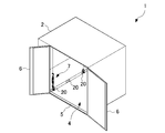
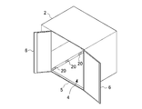
- FIG. 1 It is a perspective view showing appearance of aviation container 1 in an embodiment of the present invention. It is a perspective view which shows the state which opened the opening / closing door 6 of the container 1 for aviation.
- 2 is a perspective view showing an appearance of a container body 2.
- FIG. 2 is a perspective view showing an appearance of a support metal fitting 20.
- FIG. FIG. 6 is an internal plan view showing the arrangement of support brackets 20. It is explanatory drawing which shows the structure of the storage auxiliary
- FIG. FIG. 3 is a perspective view showing a state in which a hook body 10 is attached to a support metal fitting 20.
- FIG. 2 is a perspective view showing a state in which a turnbuckle 16 is hooked on a hook body 10.
- FIG. It is explanatory drawing which shows the components for fixing the pulley 12 and the pulley 12 to the support metal fitting 20.
- FIG. FIG. 3 is a perspective view showing a state where the pulley 12 is mounted on the support metal fitting 20.
- 2 is a perspective view showing a configuration of the storage 100.
- FIG. It is a perspective view which shows the state which stored the storage 100 in the container 1 for aviation.
- FIG. 4 is an explanatory diagram showing a detailed configuration of a fixing bracket 30. It is a perspective view which shows the state which fitted the projection part 18e to the support metal fitting 20. FIG. It is a perspective view which shows the structure of the storage 100 with which the slide rail 120 was mounted
- FIG. 23 is a plan view of FIG. 22. It is a top view including the partial cross section which shows the structure of A vicinity shown in FIG. It is a perspective view which shows the state which fixed the storage auxiliary
- FIG. 4 is a perspective view showing a state in which the storage 100 is stored in the aircraft container 52.
- FIG. 1 is a perspective view showing an appearance of an aircraft container 1 according to an embodiment of the present invention
- FIG. 2 is a perspective view showing a state in which an opening / closing door 6 of the aircraft container 1 is opened.
- the aerial container 1 includes a container body 2 corresponding to a room temperature container, and a storage auxiliary device 7 according to the first embodiment of the present invention.
- the container body 2 is a substantially rectangular parallelepiped box.
- the container main body 2 in the present embodiment is of the LD3 type, and has a shape in which the vicinity of a predetermined side in a substantially rectangular parallelepiped shape is lacking in a triangular prism shape.
- the A1 direction in FIG. 1 in the container body 2 is upward, the A2 direction is downward, the B1 direction is forward, the B2 direction is backward, the C1 direction is left, and the C2 direction is right. It will be called a direction.
- the C1 and C2 directions may be collectively referred to as the left-right direction or the horizontal direction.
- An opening / closing door 6 is provided on the front side surface of the container body 2, and the opening 4 is opened by opening the opening / closing door 6.
- the carry-in port 4 is a rectangular opening, the horizontal width of the carry-in port 4 is set equal to the horizontal width of the floor surface, and the vertical width of the carry-in port 4 is set equal to the vertical width of the storage space of the container body 2.
- a step portion 5 is formed at an end portion on the carry-in port side on the floor surface in the container main body 2. The step portion 5 extends upward several cm from the floor surface in the container body 2.
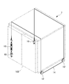
- FIG. 3 is a perspective view showing the appearance of the container body 2.
- a support fitting 20 is installed inside the container body 2.
- Various metal fittings can be fixed to the support metal fitting 20.
- the metal fitting provided with the metal ring for hooking the attachment metal fitting of the luggage fixing belt is fixed to the support metal fitting 20, and the luggage in the container body 2 is fixed so as not to move by using the luggage fixing belt. Can do.
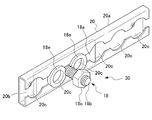
- FIG. 4 is a perspective view showing the appearance of the support fitting 20
- FIG. 5 is an internal plan view showing the arrangement of the support fitting 20.
- the support fitting 20 includes a main body portion 20a, a slit portion 20b, a widened portion 20c, and a hole portion 20d.
- the main body portion 20a is a cylindrical member whose end face shape is formed in a substantially C-shape by bending 90 degrees at two locations on both end portions extending in the longitudinal direction of the strip-shaped metal member. It is.
- the slit portion 20b is a linear gap formed between both end portions along the longitudinal direction of the main body portion 20a.
- the widened portion 20c is a portion having a wide slit width formed at a plurality of locations (six locations according to the present embodiment) of the slit portion 20b.
- the widened portion 20c is formed in an arc shape.
- the central axis of the main body portion 20a and the central line of the slit portion 20b coincide with each other on the central axis of the main body portion 20a.
- the center of the arcuate widened portion 20c is positioned at the center.
- the hole 20d is for inserting a screw 21 used to fix the support fitting 20 to the container body 2.
- the holes 20d are formed at three locations in the main body 20a facing the widened portion 20c.
- the support metal fittings 20 are fixed side by side in the lower part of the left side, the lower part of the right side, and the lower part of the rear side of the container body 2, in other words, near the floor.
- the slit portions 20 b of the three support fittings 20 are arranged so as to extend in the front-rear direction, and are fixed to the container main body 2 by screws 21.
- the head of the screw 21 enters the inside of the hole 20d, the inner surface of the support fitting 20 and the upper surface of the head of the screw 21 are flush with each other.
- FIG. 6 is an explanatory diagram showing the configuration of the storage auxiliary device 7 in the first embodiment of the present invention.
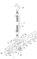
- the storage auxiliary device 7 includes hook bodies 10 and 10, pulleys 12 and 12, a wire 14, and a turnbuckle 16.
- the storage auxiliary device 7 fixes the storage 100 to the container main body 2 so that the storage 100 placed on the floor inside the container main body 2 shown in FIG. 2 does not move on the floor of the container main body 2. To do.
- the hook bodies 10 and 10 are arranged on the left side of the container body 2 on the carry-in entrance 4 side (front side) and on the back side (rear side) with respect to the carry-in entrance 4.
- the pulleys 12 and 12 are disposed on the right side of the container body 2 on the carry-in entrance 4 side (front side) and on the back side (rear side) with respect to the carry-in entrance 4.
- the wire 14 is hooked by the hook body 10 arrange
- the hook body 10 disposed on the back side (rear side) with respect to the carry-in port 4 on the left side is the first hook body
- the hook body 10 disposed on the carry-in port 4 side (front side) on the left side Is a second hook body
- a pulley 12 arranged on the back side (rear side) with respect to the carry-in port 4 on the right side is arranged on the first direction switching member, the carry-in port 4 side (front side) on the right side.
- the pulley 12 corresponds to a second direction switching member.
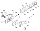
- FIG. 7 is an explanatory view showing the hook body 10 and parts for fixing the hook body 10 to the support fitting 20.
- the storage auxiliary device 7 further includes a rectangular plate 11 and a connection fitting 18.
- the hook body 10 is made of metal, and includes a ring portion 10a and a hook portion 10b extending in a hook shape from a part of the ring portion 10a.
- the rectangular plate 11 is made of a rectangular metal plate, and a hole portion 11a having the same diameter as the inner diameter of the ring portion 10a is formed at the center.
- the connection fitting 18 is configured by a slide plate 18a that can be inserted into the support fitting 20, a bolt 18b, and a nut 18c that is screwed into the bolt 18b.
- the slide plate 18a includes a metal plate 18d, protrusions 18e and 18e, and a hole 18f.
- the metal plate 18d is a rectangular plate and has a size such that the two widened portions 20c face each other when inserted into the support metal fitting 20.
- the protrusions 18e and 18e are annular protrusions that are formed in a portion where the two widened portions 20c of the metal plate 18d face each other and can be fitted into the widened portion 20c.
- the hole 18f is formed between the pair of protrusions 18e and 18e, and the bolt 18b is inserted into the hole 18f.
- the hole 18f has the same diameter as the slit width of the slit 20b.
- the hole 18f faces the slit 20b when the metal plate 18d is inserted into the support metal fitting 20.
- the region included in the hole 18f in the pair of protrusions 18e and 18e is deleted.
- a part of a region where the pair of protrusions 18e and 18e are close to each other is deleted, and a cylindrical space through which the male screw part 18g of the bolt 18b passes between the protrusions 18e and 18e. Is formed.
- the bolt 18b includes a male screw portion 18g inserted into the hole 18f and a head portion 18h formed at the base end portion of the male screw portion 18g.
- the male screw portion 18g has a substantially cylindrical shape with a diameter smaller than the slit width of the slit portion 20b, and can be inserted into the slit portion 20b.
- the head 18h has a disk shape with a diameter larger than the slit width of the slit portion 20b.
- the bolt 18b is inserted into the hole 18f from the opposite side of the plane on which the protrusions 18e and 18e are disposed on the metal plate 18d, the head 18h abuts on the periphery of the hole 18f, and the tip of the male screw 18g Projecting from between the protrusions 18e, 18e.
- the bolt 18b since the male screw part 18g passes between the pair of protrusions 18e, 18e, the bolt 18b is supported by the pair of protrusions 18e, 18e, and the bolt 18b does not tilt, and the protrusions 18e, 18e It is maintained in a state protruding from between.
- the inner diameter of the ring portion 10a in the hook body 10 and the diameter of the hole portion 11a in the rectangular plate 11 are set such that the bolt 18b can be inserted.
- the rectangular plate 11 is set to a size that can cover the protrusions 18e and 18e of the slide plate 18a.
- the operator inserts the slide plate 18a into the support bracket 20, positions the bolt 18b at the center of the two adjacent widened portions 20c, 20c in the slit portion 20b, and the projecting portions 18e, 18e to the two widened portions 20c, By pulling the bolt 18b so as to oppose 20c, as shown in FIG. 8, the protrusions 18e and 18e of the slide plate 18a are fitted into the widened portions 20c and 20c. Thereby, the sliding movement of the slide plate 18a with respect to the support metal fitting 20 is restricted, and the state in which the bolt 18b protrudes from the support metal fitting 20 is maintained.
- an operator passes the hole 11a of the rectangular plate 11 through the tip of the bolt 18b, the ring portion 10a of the hook body 10, and tightens the nut 18c to tighten the projections 18e and 18e, the rectangular plate 11 and the hook body.
- the hook body 10 is fixed to the support fitting 20 by bringing the 10 and 10 into close contact with each other.
- the turnbuckle 16 has a pair of hook members 16 a, 16 a having one end formed in a hook shape and a thread formed on the other end, and a screw on the hook members 16 a, 16 a. And an annular main body member 16b having two screw holes to be joined.
- the screw threads of the pair of hook members 16a and 16a are reverse to each other. Further, the thread grooves of the two screw holes of the main body member 16b are also reversely threaded.
- the hook members 16a and 16a are arranged coaxially, and are threaded inside the main body member 16b.
- the ends of the bolt parts where the cuts are made face each other. With such a configuration, the hook members 16a and 16a move away from or approach each other according to the rotation of the main body member 16b.
- One hook member 16 a of the turnbuckle 16 is hung on the hook body 10 fixed to the front support metal fitting 20 on the left side surface of the container main body 2.
- the other hook member 16a is hooked to the end of the wire 14 as shown in FIG.
- FIG. 10 is an explanatory view showing the pulley 12 and parts for fixing the pulley 12 to the support fitting 20.
- the pulley 12 has a central hole 12a in the center, and a ring-shaped groove 12b is formed on the outer peripheral surface. Further, the pulley 12 is fixed to the support fitting 20 using the rectangular plate 11, the connecting fitting 18, and the flange body 19.
- the rectangular plate 11 and the connecting fitting 18 are as described above.
- the flange body 19 includes a cylindrical portion 19a and a flange portion 19b extending from one end of the cylindrical portion 19a in a direction perpendicular to the central axis.
- the inner diameter of the cylindrical portion 19a is the same as that of the hole portion 11a of the rectangular plate 11, and is large enough to pass the bolt 18b.
- the outer diameter of the cylindrical portion 19a is set slightly smaller than the inner diameter of the central hole 12a of the pulley 12. That is, the cylindrical portion 19a can be passed through the central hole 12a of the pulley 12.
- the worker inserts the slide plate 18a into the support fitting 20, and the bolt 18b is inserted into the two adjacent widened portions 20c and 20c in the slit portion 20b.
- the projection 18e, 18e is inserted into the two adjacent widened portions 20c and 20c in the slit portion 20b.
- the operator passes the hole 11a of the rectangular plate 11 through the tip of the bolt 18b, and further passes the cylindrical portion 19a of the flange body 19 through the central hole 12a of the pulley 12 and then passes the cylindrical portion 19a through the bolt 18b.
- a nut 18c is attached to the tip of the bolt 18b, and the nut 18c is tightened to bring the projections 18e, 18e, the rectangular plate 11 and the cylindrical portion 19a into close contact with each other.
- the pulley 12 is fixed to the support fitting 20 in a state where the pulley 12 can rotate about the cylindrical portion 19 a of the flange body 19.
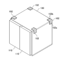
- FIG. 12 is a perspective view showing the configuration of the storage 100.
- the storage 100 is a rectangular parallelepiped box that is slightly smaller than the storage space in the container body 2.
- the storage 100 is provided with a double door opening / closing door 110 on the front surface. By opening the opening / closing door 110, it is possible to store and take out articles from the storage 100.
- a storage unit for storing a plurality of cryogens is provided on the inner wall surface of the storage unit 100.
- the interior of the storage unit 100 is stored. Refrigerant is spread on the wall. Thereby, storage 100 comes to have a cold storage function.
- FIG. 13 is a perspective view showing a state where the storage 100 is stored in the aircraft container 1.
- the worker fixes the hook bodies 10, 10 and the pulleys 12, 12 to the corresponding support bracket 20 as shown in FIGS.
- the hook bodies 10, 10 are fixed to the support fitting 20 on the left side of the container body 2 on the carry-in entrance 4 side (front side) and the back-side (rear side) with respect to the carry-in entrance 4 by the connecting fitting 18.
- the pulleys 12, 12 are fixed to the support fitting 20 on the right side of the container body 2 on the carry-in entrance 4 side (front side) and the back-side (rear side) with respect to the carry-in entrance 4 by the connecting fitting 18. That is, the hook bodies 10 and 10 and the pulleys 12 and 12 are fixed to the support metal fittings 20 arranged in the vicinity of the four corners of the floor surface on the left and right side surfaces.
- one end of the wire 14 formed in a ring shape is hooked on the rear hook body 10 as shown in FIG.
- the wire 14 is extended upwards, for example, it is turned from the left side of the ceiling of the container main body 2 to the right side, is lowered along the right side wall surface of the container main body 2, and is wound around the rear pulley 12.
- the wire 14 is extended just under the front pulley 12, and the other end part of the wire 14 is pulled out outside.
- the wire 14 may be in a loose state.
- the wire 14 laid on the ceiling of the container body 2 may be temporarily fixed with an adhesive tape or the like.
- the worker pulls the wire 14 forward and applies tension to the wire 14.
- the wire 14 comes off from the adhesive tape and comes into contact with the rear side of the upper portion of the storage 100 and is in close contact with the rear pulley 12.
- the worker winds the wire 14 around the front pulley 12 and then extends upward, extends from the right side to the left side in front of the upper portion of the storage 100, and lowers the wire 14 along the left side wall surface of the container body 2.
- the other end portion of the wire 14 formed in a ring shape and the front hook body 10 are connected by a turnbuckle 16.
- the main body member 16b of the turnbuckle 16 is rotated to lower the other end portion of the wire 14 downward, thereby strengthening the fastening of the wire 14 to the storage 100.
- the storage 100 is fixed by the storage auxiliary device 7 so as not to move in the container body 2.
- a guide plate 102 is a member formed in an L shape with a predetermined curvature by pressing a metal plate having a smooth surface, and a smooth surface portion 102a with which the wire 14 is slidably contacted. Rib portions 102b and 102b are formed on both sides of 102a and prevent the wire 14 from coming off the guide plate 102.
- an operator operates the turnbuckle 16 to firmly fix the storage 100 accommodated in the container body 2 by the wire 14 so as not to move. Is possible. Further, since the worker can reach the gap between the container body 2 and the storage 100 and operate the turnbuckle 16 from the outside of the container body 2, the wire 14 can be easily tightened and loosened. It becomes possible.
- the storage auxiliary device 8 of the second embodiment described below is made in view of such problems, and assists in loading and unloading the storage 100 with respect to the container body 2.
- symbol is attached
- the storage auxiliary device 8 is fixed to the floor inside the container body 2 and places the storage 100.
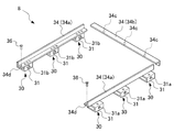
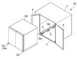
- FIG. 15 is an explanatory diagram showing a configuration of the storage auxiliary device 8 according to the second embodiment of the present invention, and the storage auxiliary device 8 corresponds to a plurality of fixing brackets 30, rail bodies 34, and engaging members. And a screw 36.
- FIG. 16 is an explanatory view showing a detailed configuration of the fixing bracket 30.
- the fixing bracket 30 includes a support base 31 that supports the rail body 34 and the connecting bracket 18 used in the first embodiment.
- the support base 31 is a rectangular cylindrical metal member, and is disposed at the left and right ends of the floor surface of the container body 2.
- the rail body 34 is placed and fixed on the upper surface of the support base 31.
- the rail body 34 is disposed within the range of the carry-in port 4 when the carry-in port 4 is viewed from the front of the container body 2.
- the uppermost part of the step part 5 and the surface of the rail bodies 34a and 34a become the same height.
- a hole portion 31a into which the male screw portion 18g of the bolt 18b can be inserted is formed on the side surface facing the left side surface or the right side surface of the container body 2. Moreover, the hole part 31b is formed in the opposing part of the hole part 31a in the side surface facing this side surface.
- the hole 31b has a larger diameter than the hole 31a, and is formed so that a nut 18c and a tool for rotating the nut 18c can be inserted.
- the operator inserts the slide plate 18a into the support bracket 20, positions the bolt 18b at the center of the two adjacent widened portions 20c, 20c in the slit portion 20b, and the projecting portions 18e, 18e to the two widened portions 20c, By pulling the bolt 18b so as to face 20c, as shown in FIG. 17, the protrusions 18e and 18e of the slide plate 18a are fitted into the widened portions 20c and 20c. Thereby, the sliding movement of the slide plate 18a with respect to the support metal fitting 20 is restricted, and the state in which the bolt 18b protrudes from the support metal fitting 20 is maintained.
- the operator passes the hole 31a of the support base 31 through the tip of the bolt 18b and tightens the nut 18c to bring the protrusions 18e, 18e and the support base 31 into close contact with each other.
- Fixed to. As described above, a total of six support bases 31 are fixed to the floor surface of the container body 2 along the two long sides extending in the front-rear direction.
- the three rail bodies 34 are long members having an L-shaped cross section.
- the surfaces of the three rail bodies 34 are smooth surfaces with little friction.
- the three rail bodies 34 are two rail bodies 34 a and 34 a disposed at the left and right end portions on the floor surface of the container main body 2, and rails disposed at the rear end portions on the floor surface of the container main body 2. It consists of a body 34b.
- the two rail bodies 34a and 34a are fixed on the three support bases 31 with flat screws or the like.
- a tapered recess is formed in the upper part of the screw hole formed in the two rail bodies 34a, 34a for inserting the flat screw so that the head of the flat screw does not protrude from the rail surface.
- a hole 34c (see FIG. 15) into which the bolt 18b can be inserted is formed at a portion facing the support fitting 20 fixed to the rear side surface.
- the support metal fitting 20 has six widened portions 20c, and the widened portion 20c in the six widened portions 20c can be appropriately selected as to which the protruding portions 18e and 18e are fitted.
- the rearmost support metal fitting 20 is provided. It is desirable to fit the protrusions 18e and 18e to the two widened portions 20c located at the same position. That is, since it is necessary to get over the four widened portions 20c before the protrusions 18e and 18e are detached from the support fitting 20, the storage auxiliary device 8 does not move to the outside of the container body 2.
- the storage 100 is placed on the three rail bodies 34a, 34a, 34b installed inside the container body 2 in this way.
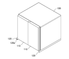
- FIG. 18 is a perspective view showing the configuration of the storage 100.
- the storage 100 is a rectangular parallelepiped box that is slightly smaller than the storage space in the container body 2 and can be placed on the three rail bodies 34.
- the storage 100 is provided with a double door opening / closing door 110 on the front surface. By opening the opening / closing door 110, it is possible to store and take out articles from the storage 100.
- Slide rails 120 and 120 that are in sliding contact with the upper surfaces of the rail bodies 34 a and 34 a (see FIG. 15) when the storage 100 is moved are fixed to the two long side portions extending in the front-rear direction on the lower surface of the storage 100.
- the lengths of the slide rails 120 and 120 are substantially the same as the lengths of the rail bodies 34a and 34a (see FIG. 15), and the end portions on the front side of the slide rails 120 and 120 fixed to the storage 100 are provided. , Protruding from the bottom of the storage 100.
- a hole 34d is formed at the front end of the rail body 34b, and a hole is formed at the front end of the slide rail 120 as shown in FIG. A portion 120a is formed. And in the state where storage 100 was stored in container main part 2, hole 34d and hole 120a correspond. By inserting the screw 36 into the hole 120a, the rail body 34b and the slide rail 120 are engaged, and the storage 100 is fixed to the container body 2.
- FIG. 19 is a perspective view showing a state before the storage container 100 is stored in the aviation container 50
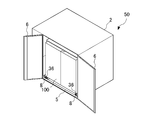
- FIG. 20 is a perspective view showing a state in which the storage container 100 is stored in the aviation container 50.
- the aerial container 50 is configured by fixing the storage auxiliary device 8 to the floor surface of the container body 2 as shown in FIG.
- the storage auxiliary device 8 When the storage auxiliary device 8 is fixed to the floor surface of the container main body 2, first, an operator fixes the support base 31 to the container main body 2 using the connection fitting 18 (see FIG. 16), and then supports the storage auxiliary device 8.
- the rail body 34 a is fixed to the base 31.
- the support base 31 may be fixed to the container body 2 after the support base 31 is fixed to the rail body 34a. Further, the worker fixes the rail body 34 b (see FIG. 15) to the container main body 2 using the connection fitting 18.
- the storage 100 When the storage 100 is carried into the aviation container 50, first, an operator uses the rear end of the slide rails 120 and 120 in the storage 100 as the front end of the rail bodies 34 a and 34 a. Put it on. When the storage 100 is pushed rearward, the storage 100 moves into the aviation container 50 along the rail bodies 34a and 34a, and the lower part on the rear side of the storage 100 is placed on the rail body 34b. The storage 100 stops. Then, the worker fixes the storage 100 to the container body 2 by inserting the screws 36 into the holes 120a. As a result, the storage 100 is housed in the aircraft container 50 as shown in FIG.
- the articles to be put in the storage 100 may be put in the storage 100 before storing the storage 100 in the aircraft container 50, or after storing the storage 100 in the aircraft container 50. May be stored.
- a load on the three rail bodies 34 and the support base 31 may be reduced by inserting a pallet into a region surrounded by the three rail bodies 34 on the floor surface of the container body 2.
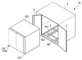
- FIG. 21 is an explanatory view showing the appearance of an aircraft container 52 including the storage auxiliary device 9 according to the third embodiment of the present invention.
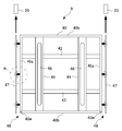
- FIG. 22 is a perspective view showing the external appearance of the storage auxiliary device 9 in the second embodiment of the present invention.
- FIG. 23 is a plan view of FIG.
- the same members as those in the storage auxiliary device 8 of the second embodiment are denoted by the same reference numerals, and detailed description thereof is omitted.
- the aviation container 52 includes a container body 3 and a storage auxiliary device 9.
- the container main body 3 has a configuration in which the stepped portion 5 is deleted from the container main body 2 shown in FIGS.
- the storage auxiliary device 9 is fixed to the container body 3 while being placed on the floor surface of the container body 3.
- the storage auxiliary device 9 includes a frame body 40, two reinforcing bars 42, 42, two support plates 44, 44, a fixing bracket 46, an engaging member. And a screw 49 corresponding to.
- the frame body 40 is a combination of rectangular rod-like members 40 a, 40 a, 40 b, 40 b in a rectangular shape.
- the length of the rod-like members 40 b, 40 b extending in the left-right direction in the frame body 40 is the floor surface of the container body 3.
- the length of the bar-like members 40a, 40a extending in the front-rear direction is shorter than the length of the floor surface of the container body 3 in the front-rear direction.
- the length is set to be shorter by the protrusion of one support fitting 20. Further, as shown in FIG. 22, holes 40c and 40d are formed in the frame body 40.
- FIG. 24 is a plan view including a partial cross section showing a configuration in the vicinity of A shown in FIG. Further, in the state where the storage auxiliary device 9 is placed on the floor surface of the container body 3, a hole 40c into which the bolt 18b can be loosely inserted is formed at a portion of the rod-shaped member 40a facing the support metal fitting 20. ing. Further, a hole 40d larger than the hole 40c is formed in a portion of the rod-like members 40a, 40a facing the holes 40c, 40c on the inner surface of the frame body 40. That is, three holes 40c and large holes 40d are formed in the rod-like members 40a and 40a, respectively.
- the reinforcing rod 42 is formed of a rectangular tube rod-like member whose height is lower than the rod-like members 40a and 40b constituting the frame body 40.
- the two reinforcing bars 42, 42 are arranged inside the frame body 40 in the front-rear direction so as to be parallel to the bar-shaped members 40b, 40b, and both ends are fixed to the bar-shaped members 40a, 40a.
- the reinforcing rod 42 is fixed downward with respect to the rod-shaped members 40a and 40a, and a step is formed by the upper surfaces of the rod-shaped members 40a and 40a and the upper surface of the reinforcing rod 42.
- the two support plates 44, 44 are formed of a belt-like plate, and are arranged on the reinforcing rod 42 in the left-right direction so as to be parallel to the rod-shaped members 40a, 40a inside the frame body 40, and both end portions are rod-shaped. It is fixed to the members 40b and 40b.
- the thickness of the support plate 44 is set to the height of the step between the upper surfaces of the rod-like members 40 a and 40 a and the upper surface of the reinforcing rod 42. For this reason, the upper surface of the frame body 40 and the upper surfaces of the two support plates 44, 44 are flush with each other. Note that the upper surface of the frame body 40 and the upper surfaces of the two support plates 44, 44 are formed as smooth surfaces with little friction.
- the support plate 44 is fixed with a bearing portion 48 in which a plurality of bearings are arranged in the front-rear direction.
- the fixture 46 is composed of a slide plate 47 and bolts 18b and nuts 18c used in the first embodiment.
- the slide plate 47 includes a metal plate 47a, protrusions 47b and 47b, and a hole 47c.
- the metal plate 47a is a strip-shaped rectangular plate that has the same length as the rod-shaped member 40a and can be inserted into the support fitting 20. Dimensions other than the length in the longitudinal direction of the metal plate 47a are the same as those of the metal plate 18d shown in FIG.
- the protrusions 47b and 47b and the hole 47c have the same shape as the protrusions 18e and 18e and the hole 18f shown in FIG.
- the protrusions 47b and 47b and the hole 47c are provided in three places on the metal plate 47a. Specifically, when the metal plate 47a is inserted into the three support fittings 20, the protrusions on the metal plate 47a are arranged so that the protrusions 47b and 47b face the two widened portions 20c and 20c in each support fitting 20. The positions of the portions 47b and 47b and the hole 47c are set.
- the bolt 18b is inserted into the hole 47c from the opposite side of the plane on which the protrusions 47b, 47b of the metal plate 47a are arranged, the head 18h abuts on the periphery of the hole 47c, and the male screw 18g is the protrusion 47b. , 47b.
- the slide plates 47 and 47 are attached to the rod-shaped member 40a by inserting the bolts 18b into the three hole portions 40c of the rod-shaped member 40a and screwing the nut 18c to the tip of the bolt 18b.
- the nut 18c is screwed to the bolt 18b to such an extent that the slide plates 47, 47 can slide in the left-right direction.
- the projecting portions 47b and 47b are opposed to the two widened portions 20c and 20c in the support metal fittings 20 that are arranged in the lower part of the left side and the lower part of the right side, respectively, and by tightening the nut 18c, The protruding portions 47b and 47b are fitted to the widened portions 20c and 20c, and the storage auxiliary device 9 is mounted on the container main body 3. Thereby, the container 52 for aviation is comprised.
- the storage 100 When storing the storage 100 in the aviation container 52, first, an operator places the rear end of the slide rails 120, 120 in the storage 100 on the front end of the frame body 40. Then, the storage 100 is pushed backward. Thereby, the storage 100 moves to the inside of the container main body 3 while being in sliding contact with the rod-shaped members 40 a and 40 a and the support plates 44 and 44. That is, the rod-like members 40a and 40a have the same function as the rail bodies 34a and 34a in the second embodiment shown in FIG. Moreover, the bearing part 48 contacts the lower surface of a storage, and rotates along the moving direction of a storage.
- the storage 100 stops. In this state, the storage 100 is stored in the aviation container 52, and the door 6 can be closed.
- a hole 40 e is formed at the front end of the frame body 40
- a hole 120 a is formed at the front end of the slide rail 120. ing.
- the hole 40d and the hole 120a coincide.
- the worker inserts the screw 49 into the hole 120a
- the slide rail and the frame body 40 are engaged, and the storage 100 is fixed to the container body 3.
- the storage container 100 is stored in the container 52 for use.
- the container main body 2, the support metal fitting 20 provided inside the container main bodies 2 and 3, which are existing normal temperature containers, are used. It is possible to stably fix the storage 100 having a special function in the interior of 3. For this reason, it becomes easy to install the storage which has a cold storage function close to the dimension of the storage space of a normal temperature container in a normal temperature container, and it becomes possible to use a normal temperature container as a container which has a cold storage function.
- the two protruding portions 18e (47b) are fitted to the two adjacent widened portions 20c in the support metal fitting 20 having the six widened portions 20c, thereby storing the same. Since the storage auxiliary device 8 (9) is fixed to the container main body 2 (3), even if a large force is applied forward to the storage auxiliary device 8 (9), the storage auxiliary device 8 (9) Can be reliably prevented from coming off the support fitting 20.
- the storage auxiliary device 8 of the second embodiment since the step portion 5 is formed, even if the bolt 18b is broken and the support base 31 and the support bracket 20 are separated, the support base Since 31 abuts on the stepped portion 5, it is possible to prevent the support base 31 and the rail body 34a from falling.
- the screws 36 (49) are used to fix the storage 100 to the container body 2 (3), but the slide rail 120 is attached to the rail body 34 or the frame body 40. Other members may be used as long as they can be engaged.
- the storage 100 is a storage having a cold-retaining function, but may be a storage having a moisturizing function and a heat-retaining function.
- the room temperature container can be used as a container having another function other than the cold insulation function.
- the container main bodies 2 and 3 are of the LD3 type, but can be applied to containers of other standards.
- the two protruding portions 18e (47b) are fitted to the two adjacent widened portions 20c among the six widened portions 20c, but the number of the protruding portions 18e (47b) May be three or more.
Landscapes
- Engineering & Computer Science (AREA)
- Mechanical Engineering (AREA)
- Aviation & Aerospace Engineering (AREA)
- Transportation (AREA)
- Warehouses Or Storage Devices (AREA)
Abstract
L'invention concerne un dispositif auxiliaire de boîte de stockage, avec lequel il est possible de fournir facilement à un conteneur à température ambiante existant une fonction spéciale telle qu'une fonction d'isolation du froid, une fonction de rétention de chaleur, ou une fonction de rétention d'humidité, et un conteneur d'aviation. Un dispositif auxiliaire de boîte de stockage pour ancrer une boîte de stockage, qui possède une fonction spéciale et qui est chargé dans un conteneur à température ambiante pour aviation, à l'intérieur du conteneur à température ambiante, est pourvu : d'un fil (14) qui est introduit au-dessus d'une partie supérieure de la boîte de stockage ; de corps de crochets (10, 10) et de poulies (12, 12) ancrés à des raccords de support existants (20), disposés à proximité de quatre coins d'un plancher ; d'un tendeur (16). Une extrémité du fil (14 est accrochée à un corps de crochet (10), et le fil (14) est introduit au-dessus de la partie supérieure de la boîte de stockage et est enroulé autour des poulies (12, 12). L'autre extrémité du fil (14) est couplée à l'autre corps de crochet (10) par l'intermédiaire du tendeur (16). Quand le tendeur (16) est actionné par un opérateur, la boîte de stockage est fixée par le fil (14), de façon à ancrer ainsi la boîte de stockage à l'intérieur du conteneur à température ambiante.
Priority Applications (4)
| Application Number | Priority Date | Filing Date | Title |
|---|---|---|---|
| CN201580081370.5A CN108137222B (zh) | 2015-07-17 | 2015-07-17 | 储藏库辅助装置及航空用集装箱 |
| PCT/JP2015/070604 WO2017013721A1 (fr) | 2015-07-17 | 2015-07-17 | Dispositif auxiliaire de boîte de stockage et conteneur d'aviation |
| JP2017529191A JP6456503B2 (ja) | 2015-07-17 | 2015-07-17 | 収蔵庫補助装置及び航空用コンテナ |
| US15/739,507 US10800604B2 (en) | 2015-07-17 | 2015-07-17 | Storage box auxiliary device and aviation container |
Applications Claiming Priority (1)
| Application Number | Priority Date | Filing Date | Title |
|---|---|---|---|
| PCT/JP2015/070604 WO2017013721A1 (fr) | 2015-07-17 | 2015-07-17 | Dispositif auxiliaire de boîte de stockage et conteneur d'aviation |
Publications (1)
| Publication Number | Publication Date |
|---|---|
| WO2017013721A1 true WO2017013721A1 (fr) | 2017-01-26 |
Family
ID=57834938
Family Applications (1)
| Application Number | Title | Priority Date | Filing Date |
|---|---|---|---|
| PCT/JP2015/070604 Ceased WO2017013721A1 (fr) | 2015-07-17 | 2015-07-17 | Dispositif auxiliaire de boîte de stockage et conteneur d'aviation |
Country Status (4)
| Country | Link |
|---|---|
| US (1) | US10800604B2 (fr) |
| JP (1) | JP6456503B2 (fr) |
| CN (1) | CN108137222B (fr) |
| WO (1) | WO2017013721A1 (fr) |
Cited By (2)
| Publication number | Priority date | Publication date | Assignee | Title |
|---|---|---|---|---|
| CN108556729A (zh) * | 2018-01-30 | 2018-09-21 | 天津邬金机械设备有限公司 | 一种自卸车集装箱锁紧装置 |
| GB2564411A (en) * | 2017-07-06 | 2019-01-16 | Htl Group Ltd | Containerised system with modules |
Families Citing this family (6)
| Publication number | Priority date | Publication date | Assignee | Title |
|---|---|---|---|---|
| CN111099187B (zh) * | 2018-10-26 | 2024-06-25 | 青岛中集特种冷藏设备有限公司 | 航空蓄能保温集装箱 |
| CN112249336A (zh) * | 2020-09-06 | 2021-01-22 | 重庆领直航科技有限公司 | 无人机空投装置 |
| CN112340005A (zh) * | 2020-11-13 | 2021-02-09 | 辽宁科技大学 | 一种基于快递接收柜的多旋翼快递无人机 |
| CN112502493B (zh) * | 2020-11-27 | 2022-05-24 | 上海建工五建集团有限公司 | 一种不同规格集装箱房屋紧固装置及紧固方法 |
| CN112543562B (zh) * | 2020-12-04 | 2022-04-15 | 徐州腾耀电气设备有限公司 | 一种基于plc平台的智能数显式电力控制仪表 |
| CN114537914B (zh) * | 2022-04-26 | 2022-07-05 | 江苏振邦医用智能装备有限公司 | 一种内置安全机构的医疗物资物流用集装箱 |
Citations (4)
| Publication number | Priority date | Publication date | Assignee | Title |
|---|---|---|---|---|
| JPS54159082A (en) * | 1978-06-03 | 1979-12-15 | Alusuisse | Freight container |
| JPH05139488A (ja) * | 1991-11-08 | 1993-06-08 | Riken Light Metal Ind Co Ltd | 保冷式コンテナの冷却材収納箱 |
| JP2001354291A (ja) * | 2000-06-12 | 2001-12-25 | Nippon Express Co Ltd | 航空輸送用コンテナおよび航空輸送システム |
| JP2004315071A (ja) * | 2003-04-21 | 2004-11-11 | Nippon Express Co Ltd | 航空コンテナ |
Family Cites Families (10)
| Publication number | Priority date | Publication date | Assignee | Title |
|---|---|---|---|---|
| US2625118A (en) * | 1949-03-22 | 1953-01-13 | Lockheed Aircraft Corp | Aircraft cargo floor |
| US2701068A (en) * | 1951-07-27 | 1955-02-01 | Douglas Aircraft Co Inc | Cargo loading hoist |
| US3966075A (en) * | 1975-01-10 | 1976-06-29 | Schultz Gerhard L | Cargo container |
| JPS582797Y2 (ja) * | 1978-12-25 | 1983-01-18 | 日本フルハ−フ株式会社 | 冷凍コンテナ−等の積荷緊締金具 |
| US4496271A (en) * | 1982-09-30 | 1985-01-29 | East/West Industries, Inc. | Restraining fittings |
| US6824338B2 (en) * | 2002-05-28 | 2004-11-30 | Satco, Inc. | Air transport modular container system |
| US7063227B2 (en) * | 2003-09-05 | 2006-06-20 | Satco, Inc. | Air cargo container |
| CA2695743C (fr) * | 2007-10-29 | 2017-03-14 | Wabash National, L.P. | Ensemble de retenue multicouche |
| EP2445816A1 (fr) * | 2009-06-22 | 2012-05-02 | Allan Grainger | Système de stockage et de transport et éléments de celui-ci |
| EP3041760A2 (fr) * | 2013-09-03 | 2016-07-13 | Freshrealm LLC | Récipient d'expédition d'aliments frais |
-
2015
- 2015-07-17 JP JP2017529191A patent/JP6456503B2/ja active Active
- 2015-07-17 WO PCT/JP2015/070604 patent/WO2017013721A1/fr not_active Ceased
- 2015-07-17 CN CN201580081370.5A patent/CN108137222B/zh active Active
- 2015-07-17 US US15/739,507 patent/US10800604B2/en active Active
Patent Citations (4)
| Publication number | Priority date | Publication date | Assignee | Title |
|---|---|---|---|---|
| JPS54159082A (en) * | 1978-06-03 | 1979-12-15 | Alusuisse | Freight container |
| JPH05139488A (ja) * | 1991-11-08 | 1993-06-08 | Riken Light Metal Ind Co Ltd | 保冷式コンテナの冷却材収納箱 |
| JP2001354291A (ja) * | 2000-06-12 | 2001-12-25 | Nippon Express Co Ltd | 航空輸送用コンテナおよび航空輸送システム |
| JP2004315071A (ja) * | 2003-04-21 | 2004-11-11 | Nippon Express Co Ltd | 航空コンテナ |
Cited By (2)
| Publication number | Priority date | Publication date | Assignee | Title |
|---|---|---|---|---|
| GB2564411A (en) * | 2017-07-06 | 2019-01-16 | Htl Group Ltd | Containerised system with modules |
| CN108556729A (zh) * | 2018-01-30 | 2018-09-21 | 天津邬金机械设备有限公司 | 一种自卸车集装箱锁紧装置 |
Also Published As
| Publication number | Publication date |
|---|---|
| JP6456503B2 (ja) | 2019-01-23 |
| CN108137222B (zh) | 2019-08-27 |
| JPWO2017013721A1 (ja) | 2018-03-22 |
| US10800604B2 (en) | 2020-10-13 |
| CN108137222A (zh) | 2018-06-08 |
| US20180186563A1 (en) | 2018-07-05 |
Similar Documents
| Publication | Publication Date | Title |
|---|---|---|
| JP6456503B2 (ja) | 収蔵庫補助装置及び航空用コンテナ | |
| US11117645B2 (en) | Cargo hold component system for convertible cargo hold | |
| US11964702B2 (en) | Vehicle rack assembly | |
| KR101648853B1 (ko) | 이동식 발전기 및 냉각 시스템 | |
| EP3587266B1 (fr) | Système de harnais de routage et d'actionnement gérés | |
| US20180237216A1 (en) | Removable container shipping frame for vehicle | |
| US20190077294A1 (en) | Box link vertical track | |
| RU2531887C1 (ru) | Транспортировочная рама для контейнеров | |
| US20030017019A1 (en) | Power screw load retention apparatus and system | |
| US10968011B1 (en) | Pallet pocket reusable system | |
| BRPI0621388A2 (pt) | sistema e processo automático para guiar, reter e apertar cabos de aço em guindastes | |
| JP3156744U (ja) | 積載物固定具 | |
| KR101473974B1 (ko) | 코일 운송용 컨테이너 | |
| US10391918B2 (en) | Load bearing rail and tie-down ring assembly | |
| JPH07239173A (ja) | ショーケース | |
| US9840349B2 (en) | Pallet system for cable-enabled loading | |
| KR101326233B1 (ko) | 활어의 운반을 위한 컨테이너용 수조 | |
| CN211032556U (zh) | 一种横向v型槽卷材运输装置 | |
| KR20140003204A (ko) | 셀가이드 간격 조절장치 | |
| JP4080694B2 (ja) | 積載物固定手段付き載架台 | |
| NO347420B1 (en) | A fastening assembly for use in a carrier such as a pick-up/truck bed and a method for detachably fastening an object to a carrier such as a pick-up/truck bed | |
| JP2013106923A (ja) | 落下防止具 | |
| JP6963949B2 (ja) | 貨物支持固定用具、および貨物をコンテナ内に収容して固定する方法 | |
| JP4851262B2 (ja) | 運搬台車 | |
| CN104252733A (zh) | 自动售货机 |
Legal Events
| Date | Code | Title | Description |
|---|---|---|---|
| 121 | Ep: the epo has been informed by wipo that ep was designated in this application |
Ref document number: 15898881 Country of ref document: EP Kind code of ref document: A1 |
|
| ENP | Entry into the national phase |
Ref document number: 2017529191 Country of ref document: JP Kind code of ref document: A |
|
| NENP | Non-entry into the national phase |
Ref country code: DE |
|
| 122 | Ep: pct application non-entry in european phase |
Ref document number: 15898881 Country of ref document: EP Kind code of ref document: A1 |