WO2017014022A1 - 排気システム - Google Patents
排気システム Download PDFInfo
- Publication number
- WO2017014022A1 WO2017014022A1 PCT/JP2016/069574 JP2016069574W WO2017014022A1 WO 2017014022 A1 WO2017014022 A1 WO 2017014022A1 JP 2016069574 W JP2016069574 W JP 2016069574W WO 2017014022 A1 WO2017014022 A1 WO 2017014022A1
- Authority
- WO
- WIPO (PCT)
- Prior art keywords
- vacuum pump
- pump
- exhaust system
- gas
- vacuum
- Prior art date
- Legal status (The legal status is an assumption and is not a legal conclusion. Google has not performed a legal analysis and makes no representation as to the accuracy of the status listed.)
- Ceased
Links
Images

Classifications
-
- F—MECHANICAL ENGINEERING; LIGHTING; HEATING; WEAPONS; BLASTING
- F04—POSITIVE - DISPLACEMENT MACHINES FOR LIQUIDS; PUMPS FOR LIQUIDS OR ELASTIC FLUIDS
- F04D—NON-POSITIVE-DISPLACEMENT PUMPS
- F04D19/00—Axial-flow pumps
- F04D19/02—Multi-stage pumps
- F04D19/04—Multi-stage pumps specially adapted to the production of a high vacuum, e.g. molecular pumps
- F04D19/042—Turbomolecular vacuum pumps
-
- F—MECHANICAL ENGINEERING; LIGHTING; HEATING; WEAPONS; BLASTING
- F04—POSITIVE - DISPLACEMENT MACHINES FOR LIQUIDS; PUMPS FOR LIQUIDS OR ELASTIC FLUIDS
- F04B—POSITIVE-DISPLACEMENT MACHINES FOR LIQUIDS; PUMPS
- F04B37/00—Pumps having pertinent characteristics not provided for in, or of interest apart from, groups F04B25/00 - F04B35/00
- F04B37/10—Pumps having pertinent characteristics not provided for in, or of interest apart from, groups F04B25/00 - F04B35/00 for special use
- F04B37/14—Pumps having pertinent characteristics not provided for in, or of interest apart from, groups F04B25/00 - F04B35/00 for special use to obtain high vacuum
- F04B37/16—Means for nullifying unswept space
-
- F—MECHANICAL ENGINEERING; LIGHTING; HEATING; WEAPONS; BLASTING
- F04—POSITIVE - DISPLACEMENT MACHINES FOR LIQUIDS; PUMPS FOR LIQUIDS OR ELASTIC FLUIDS
- F04C—ROTARY-PISTON, OR OSCILLATING-PISTON, POSITIVE-DISPLACEMENT MACHINES FOR LIQUIDS; ROTARY-PISTON, OR OSCILLATING-PISTON, POSITIVE-DISPLACEMENT PUMPS
- F04C25/00—Adaptations of pumps for special use of pumps for elastic fluids
- F04C25/02—Adaptations of pumps for special use of pumps for elastic fluids for producing high vacuum
-
- F—MECHANICAL ENGINEERING; LIGHTING; HEATING; WEAPONS; BLASTING
- F04—POSITIVE - DISPLACEMENT MACHINES FOR LIQUIDS; PUMPS FOR LIQUIDS OR ELASTIC FLUIDS
- F04D—NON-POSITIVE-DISPLACEMENT PUMPS
- F04D19/00—Axial-flow pumps
- F04D19/02—Multi-stage pumps
- F04D19/04—Multi-stage pumps specially adapted to the production of a high vacuum, e.g. molecular pumps
-
- F—MECHANICAL ENGINEERING; LIGHTING; HEATING; WEAPONS; BLASTING
- F04—POSITIVE - DISPLACEMENT MACHINES FOR LIQUIDS; PUMPS FOR LIQUIDS OR ELASTIC FLUIDS
- F04D—NON-POSITIVE-DISPLACEMENT PUMPS
- F04D19/00—Axial-flow pumps
- F04D19/02—Multi-stage pumps
- F04D19/04—Multi-stage pumps specially adapted to the production of a high vacuum, e.g. molecular pumps
- F04D19/046—Combinations of two or more different types of pumps
-
- F—MECHANICAL ENGINEERING; LIGHTING; HEATING; WEAPONS; BLASTING
- F04—POSITIVE - DISPLACEMENT MACHINES FOR LIQUIDS; PUMPS FOR LIQUIDS OR ELASTIC FLUIDS
- F04D—NON-POSITIVE-DISPLACEMENT PUMPS
- F04D25/00—Pumping installations or systems
- F04D25/16—Combinations of two or more pumps ; Producing two or more separate gas flows
-
- F—MECHANICAL ENGINEERING; LIGHTING; HEATING; WEAPONS; BLASTING
- F05—INDEXING SCHEMES RELATING TO ENGINES OR PUMPS IN VARIOUS SUBCLASSES OF CLASSES F01-F04
- F05D—INDEXING SCHEME FOR ASPECTS RELATING TO NON-POSITIVE-DISPLACEMENT MACHINES OR ENGINES, GAS-TURBINES OR JET-PROPULSION PLANTS
- F05D2260/00—Function
- F05D2260/60—Fluid transfer
- F05D2260/607—Preventing clogging or obstruction of flow paths by dirt, dust, or foreign particles
Definitions
- the present invention relates to an exhaust system used as a means for exhausting gas from a process chamber and other chambers in a semiconductor manufacturing apparatus, a flat panel display manufacturing apparatus, and a solar panel manufacturing apparatus, and in particular, the entire exhaust system. Therefore, it is possible to prevent gas condensation and early overheating in the vacuum pump without increasing the cost, and it is suitable for expanding the operating conditions of the entire exhaust system such as a gas flow rate capable of continuous exhaust.
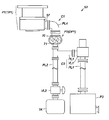
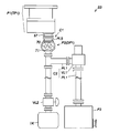
- this type of exhaust system S100 conventionally has, for example, first and second vacuum pumps P101 and P102 connected in series, and these vacuum pumps P101 and P102 and their connection C1 (specifically, Specifically, the gas containing condensable gas is exhausted through a pipe PL6 connecting the two vacuum pumps P101 and P102 and a valve VL1 provided in the middle of the pipe PL6.
- the first vacuum pump P101 is a turbo molecular pump
- the second vacuum pump P102 is a known positive displacement pump as a roughing pump.
- the condensability in the present application indicates the property of changing phase from gas to solid or liquid depending on pressure and temperature according to the characteristics of the vapor pressure curve.
- the turbo molecular pump (first vacuum pump P101) has less vibration due to the structural feature that the rotating body inside the pump is supported in a non-contact manner by a magnetic bearing. Used in a process chamber in a clean room.
- the positive displacement pump (second pump P102) is susceptible to vibration due to the structural feature that the rotating body is not supported in a non-contact manner inside the pump, so it is several meters away from the chamber and the turbo molecular pump. It is often used by installing it in a new location (for example, downstairs in a clean room). In the case of such a usage pattern, the following ⁇ Countermeasure 1 >> to ⁇ Countermeasure 3 >> are often taken in consideration of piping loss. *
- Countermeasure 1 A thick pipe PL6 having a diameter of about 75 mm to 100 mm is used as the pipe PL6 for connecting the turbo molecular pump (first vacuum pump P101) and the positive displacement pump (second vacuum pump P102).
- second vacuum pump P102 In order to set the outlet pressure of the pipe PL6 low, a large volume transfer pump (generally, a roots pump) is used as the second vacuum pump P102.
- Countermeasure 3 The composite pump WP of FIG. 13 is used as the first vacuum pump P101 so that the exhaust operation can be performed even when the outlet pressure of the pipe PL6 is high. *
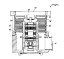
- the composite pump WP of FIG. 13 is known as a pump of a type that combines the function of a turbo molecular pump and the function of a thread groove pump (see, for example, Patent Document 1). *
- the turbo molecular pump function unit (blade exhaust mechanism 50) of the composite pump WP includes a plurality of rotor blades 51 provided on the outer peripheral surface of the rotor 54 and a pump case 55 that accommodates the rotor 54 as shown in FIG.
- a plurality of fixed blades 52 fixed to the peripheral surface are arranged in multiple stages, and the rotor blades 51 that rotate integrally with the rotor 54 and stationary stationary blades 52 impart momentum in a predetermined direction to gas molecules.
- the gas molecules in the chamber are exhausted from the suction port 56 toward the exhaust port 57. This also applies to the turbo molecular pump. *
- the gas exhausted by these vacuum pumps P101 and 102 includes condensable gas.
- the condensable gas in the gas condenses above its condensing pressure, and the condensed gas component accumulates inside the pump, thereby blocking the gas flow path of the turbo molecular pump, exhausting Problems such as performance degradation and overheating occur.
- the condensed gas component deposits contact the rotor blades of the turbo-molecular pump and the rotor blades are damaged.
- the present invention has been made to solve the above-mentioned problems, and its purpose is to prevent gas condensation and premature overheating in the vacuum pump without causing an increase in the cost of the entire exhaust system.
- An object of the present invention is to provide an exhaust system suitable for expanding the operating conditions of the entire exhaust system, such as a gas flow rate that can be exhausted.
- the present invention connects a first vacuum pump and a second vacuum pump in series as at least two pumps, and a gas containing a condensable gas through these vacuum pumps and their connection parts.
- the exhaust system for exhausting air by installing the second vacuum pump in the vicinity of the first vacuum pump, the internal environment of the connection portion is determined from the vapor pressure curve of the condensable gas flowing through the interior. It is set to be an environment included in the lower gas phase region.
- the first vacuum pump and the second vacuum pump may be connected and integrated. *
- a vibration proof structure may be provided in the connection portion.
- the first vacuum pump may be located upstream from the second vacuum pump and may be a turbo molecular pump.
- the turbo molecular pump may include a blade exhaust mechanism that exhausts the gas by a rotary blade and a fixed blade, and a structure that does not include a drag pump mechanism.
- the internal environment of the connection part is lower than the vapor pressure curve of the condensable gas flowing through the internal part.
- the environment may be set so as to be included in the gas phase region.
- the second vacuum pump may be located downstream from the first vacuum pump and may be a positive displacement pump.
- the positive displacement pump includes a heater for heating the inside of the pump, a temperature sensor for measuring the temperature in the pump, and a heating temperature of the heater using a measurement value of the temperature sensor. And a temperature control circuit for controlling.
- the positive displacement pump may include an inverter circuit, and the rotation speed can be changed by the inverter circuit.
- the positive displacement pump may have a low-speed operation function that enables operation at a rotation speed lower than the rotation speed during normal operation.
- control circuit of at least one of the first vacuum pump and the second vacuum pump is housed in a housing, and the housing is disposed in at least one of the housings. It is good also as the structure connected and integrated with the said vacuum pump.
- a heat insulating means may be provided at a connection portion between the first vacuum pump or the second vacuum pump and the housing of the control circuit.
- a third vacuum pump may be disposed and connected downstream of the second vacuum pump.
- the internal environment of the second vacuum pump is set to be an environment included in a solid phase region above the vapor pressure curve of the condensable gas flowing through the second vacuum pump. Also good. *
- the internal environment of the second connection portion connecting the second vacuum pump and the third vacuum pump is higher than the vapor pressure curve of the condensable gas flowing through the interior. It may be characterized in that the environment is set to be included in the phase region.
- a trap or a storage tank that captures a condensed or solidified gas component is provided in the second connection portion that connects the second vacuum pump and the third vacuum pump. Also good.
- the environment inside the connection part of the two vacuum pumps is It set so that it might become the environment contained in the gaseous-phase area
- a configuration in which a second vacuum pump is installed in the vicinity of the first vacuum pump instead of the conventional selective heating is employed. Since the heater used for gas condensation measures can be omitted, it is possible to reduce the number of parts and the cost of the entire exhaust system, and further to reduce the energy consumption of the entire system by reducing the heater power consumption.
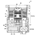
- FIG. 1 is a cross-sectional view of a turbo molecular pump that can be employed as a first vacuum pump that constitutes an exhaust system according to an embodiment of the present invention.
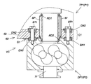
- Explanatory drawing of piping which comprises the connection part of a 1st vacuum pump and a 2nd vacuum pump.
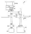
- FIG. 1 is a configuration diagram of an exhaust system according to an embodiment of the present invention
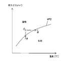
- FIG. 2 is a vapor pressure curve diagram for explaining the operating principle of the exhaust system to which the present invention is applied. *
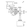
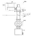
- first and second vacuum pumps P1 and P2 are connected in series as at least two pumps, and a gas containing a condensable gas is supplied through these vacuum pumps P1 and P2 and the connection portion C1.
- the gas exhausted by the exhaust system S1 exists in a chamber (not shown) to which the first vacuum pump P1 is connected, and from the chamber, the first vacuum pump P1, the connection part C1, and the second vacuum pump C2 By sequentially shifting, the air is exhausted out of the chamber.
- the chamber for example, a process chamber constituting a semiconductor manufacturing apparatus, a flat panel display manufacturing apparatus, a solar panel manufacturing apparatus, or the like is assumed, but the gas is exhausted from a chamber other than the process chamber.
- VPC indicates the vapor pressure curve of the condensable gas flowing through the connecting portion C1.
- point A in FIG. 2 indicates that in the exhaust system S1 adopting the “gas condensation countermeasure in the present invention”, the inside of the connection portion C1 connecting the two vacuum pumps P1 and P2 and the first vacuum communicating with the inside. The relationship between pressure and temperature in the vicinity of the exhaust port of the pump P1 is shown. *
- a point B in FIG. 2 is a first comparative example, and in the conventional exhaust system S100 (see FIG. 12) adopting the “conventional gas condensation countermeasure” described above, the first constituting the exhaust system S100. 1 shows the relationship between pressure and temperature in the vicinity of the exhaust port of one vacuum pump P101. *
- a point C in FIG. 2 is a second comparative example, which is an example in the case where the conventional countermeasure against gas condensation is not adopted in the conventional exhaust system S100 of FIG. 12, and the second C constituting the exhaust system S100. 1 shows the relationship between pressure and temperature in the vicinity of the exhaust port of one vacuum pump P101. *
- this “conventional gas condensation countermeasure” is achieved by increasing the internal temperature of the conventional exhaust system S100 shown in FIG. 12 without decreasing the internal pressure of the connection part C1 of the two vacuum pumps P101 and P102.
- the environment near the exhaust port of the first vacuum pump P101 is an environment included in the gas phase region below the vapor pressure curve VPC.
- the first vacuum pump P101 is likely to have a problem of so-called early overheating.
- the "gas condensation countermeasure in the present invention” is the environment in the connection part C1 and in the vicinity of the exhaust port of the first vacuum pump P1.
- the environment is set so as to be included in the gas phase region below the vapor pressure curve VPC of the condensable gas flowing through the mouth, and as a specific means for such setting, the temperature inside the connecting portion C1 is raised. Since the method of lowering the internal pressure is adopted, the above-described problem of early overheating hardly occurs in the exhaust system S1 adopting the “gas condensation countermeasure in the present invention”.
- the combination of the countermeasure for raising the temperature inside the connection section C1 and the countermeasure for lowering the pressure inside the connection section C1 as described above It is also possible to set to be an environment included in the gas phase region.
- the first vacuum pump P1 is located upstream of the second vacuum pump P2, and specifically employs the turbo molecular pump TP1 shown in FIG. *
- the turbo molecular pump TP1 as the first vacuum pump P1 includes a blade exhaust mechanism 50 that exhausts gas with the rotary blade 51 and the fixed blade 52, and includes a Holbeck type, a Sigburn type, and a Gode type.
- the structure does not include various types of drag pump mechanisms.
- the first reason why the turbo molecular pump TP1 does not include a drag pump mechanism is that the drag pump mechanism has narrow flow paths and gaps through which gas flows, and the deposition of deposits tends to block the flow paths and gaps. It is.
- the second reason is that in the drag pump mechanism, the gas flow friction resistance increases when the gas flows through the narrow flow path and the gap as described above, and the pressure of the gas increases. By lowering, it becomes difficult to set the environment inside the connection part C1 included in the gas phase region as described above, that is, when the drag pump function is provided, it is difficult to adopt the “gas condensation countermeasure in the present invention”. That is. *
- a turbo molecular pump TP1 as the first vacuum pump P1 includes, as specific pump components, a rotor 54 supported by a magnetic bearing 53 and a plurality of outer peripheral surfaces of the rotor 54. And a plurality of fixed blades 52 fixed to the inner peripheral surface of a pump case 55 that accommodates the rotor 54, and the plurality of rotary blades 51 and the fixed blades are arranged in multiple stages, A blade exhaust mechanism 50 is formed.
- the rotor blades 51 rotate integrally with the rotor 54, and the rotating rotor blades 51 and the stationary stationary blades 52 impart momentum to gas molecules in a predetermined direction. Gas molecules are exhausted from the suction port 56 toward the exhaust port 57. *
- a lower part of the turbo molecular pump TP1 as the first vacuum pump P1 includes a water cooling plate 59 with a built-in water cooling pipe 58 in order to suppress the temperature rise of the entire pump due to heat generated in the exhaust operation.
- a cooling means 60 is provided.
- the second vacuum pump P2 is located downstream from the first vacuum pump P1 (turbo molecular pump TP1) and is composed of a volumetric transfer pump DP1. *
- a Roots pump (see FIG. 3) is adopted as a specific example of the positive displacement pump DP1, but the present invention is not limited to this.
- various types of positive displacement pumps other than the roots type such as a screw type or a claw type can be adopted.
- the positive displacement pump DP1 uses a heater (not shown) for heating the inside of the pump, a temperature sensor (not shown) for measuring the temperature in the pump, and a measured value by the temperature sensor.
- a temperature control circuit for controlling the heating temperature of the heater (for example, feedback control)
- a heat retaining function is realized.
- the positive displacement pump DP1 further includes an inverter circuit (a device that converts AC to AC again), and the rotation speed can be changed by the inverter circuit.
- the positive displacement pump DP1 has a low-speed operation function that enables operation at a rotational speed lower than the rotational speed during normal operation. This low speed operation function can be realized based on the rotation speed changing function by the inverter circuit.
- the first vacuum pump P1 and the second vacuum pump P2 are connected and integrated via the connection portion C1 (pump connection integrated structure).
- a communication hole H (see FIG. 3) is provided in the connection portion C1 of both the vacuum pumps P1 and P2.
- one end of the communication hole H communicates with the exhaust port 57 of the first vacuum pump P1
- the other end of the communication hole H communicates with the intake port 70 of the second vacuum pump P2.
- the gas exhausted from the first vacuum pump P1 is sent to the second vacuum pump P2 side via the communication path H of the connection portion C1.
- the communication hole H is preferably formed to have a large diameter over the entire hole. A plurality of them may be installed. In such a case, the fluid frictional resistance of the gas flowing through the communication hole H is reduced, so that the pressure in the connection portion C1 and in the vicinity of the exhaust port 57 of the first vacuum pump P1 communicating with the connection portion C1 is reduced. This is because the “countermeasures for gas condensation in the present invention” can be easily adopted in that it can be maintained. *
- vibration generated in the second vacuum pump P2 may be transmitted to the first vacuum pump P1 and the upstream chamber via the connection portion C1.
- a volume transfer pump DP1 such as a Roots pump
- a relatively large vibration is generated from the bearing portion of the rotating body and the timing gear for synchronizing the rotating body.
- the rotating body composed of the rotor 54 and the rotor blade 51 is supported by the magnetic bearing 53 in a non-contact manner.
- control is performed so as to keep the gap between the rotating body and the surrounding fixed portion (specifically, the gap between the rotary blade 51 and the fixed blade 52) narrow.
- the suction port 56 of the turbo molecular pump TP1 is connected to a chamber, and precision processing and work such as semiconductor etching is performed in the chamber. Therefore, the positive displacement pump DP1 (second vacuum pump P2) It is also necessary to reliably prevent the vibration generated in step 1 from being finally transmitted to the chamber through the turbo molecular pump TP1 (first vacuum pump P1). *
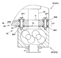
- the first vacuum pump P1 is used as a means for effectively preventing the phenomenon that the vibration generated by the second vacuum pump P2 is transmitted to the first vacuum pump P1 and the upstream chamber.
- 4 or 5 is provided at the connection portion C1 between the first vacuum pump P2 and the second vacuum pump P2.
- Specific examples of this anti-vibration structure VC are ⁇ Anti-vibration structure 1-1 >> to ⁇ Anti-vibration structure 1-3 >> below. *
- the anti-vibration structure 1-1 includes a first vacuum pump P1 and a second vacuum pump P2 that are fastened and connected with a bolt BT1.
- the vibration of the second vacuum pump P2 is absorbed by interposing vibration absorbing materials DN1 and DN2 such as rubber bushes in the fastening connection portion.
- a predetermined gap G ⁇ b> 1 is formed between the second vacuum pump P ⁇ b> 1 and the cooling means 60 by the intervention of the vibration absorbing materials DN ⁇ b> 1 and DN ⁇ b> 2.
- the gap G1 may be provided between the first vacuum pump P1 and the cooling means 60, and either one of the vibration absorbing materials may be used depending on the magnitude of vibration generated by the second vacuum pump P2. It can be omitted.
- vibration absorbing material DN1, DN2 for example, a material having high heat resistance and low hardness such as silicone rubber is preferable.
- the anti-vibration structure 1-2 employs a stepped bolt as the bolt BT1, and the vibration absorbers DN1 and DN2 are properly crushed.
- the gap G1 disappears due to the fact that the vibration absorbing materials DN1 and DN2 are not properly crushed, the second vacuum pump P2 and the cooling means 60 are in direct contact with each other, or the first vacuum pump P1 and the cooling means. This is because the vibration prevention effect by the gap G1 and the vibration absorbing materials DN1 and DN2 is reduced by direct contact with 60.
- the anti-vibration structure 1-3 includes a cylindrical spacer SP in the communication hole H provided in the connection portion C1 of the two vacuum pumps P1 and P2. And a structure in which the annular elastic members RD1 and RD2 such as O-rings are attached to the outer peripheral surface of the upper end and the lower peripheral surface of the spacer SP, and the spacer SP is connected to the communication hole H and the first through the annular elastic members RD1 and RD2.
- the configuration is set so as to be in a floating state in the exhaust port 57 of the vacuum pump P1.
- the vibration transmission in the vibration-proof structure 1-3 is reduced when the second vacuum pump P2 is vibrated and the entire second vacuum pump P2 is conical with the upper annular elastic member RD1 as a base point.
- the transmission of vibration from the second vacuum pump to the first vacuum pump is reduced.
- the anti-vibration structure VC of FIG. 5 includes the ⁇ anti-vibration structure 1-3 >> and the above-described anti-vibration structure 1-3. It includes ⁇ Anti-Vibration Structure 1-1 >> and ⁇ Anti-Vibration Structure 1-2 >>.
- the first vacuum pump P1 and the second vacuum pump P2 include a control circuit CC as means for controlling power supply to the pump, pump rotation speed, and the like.
- a control circuit CC as means for controlling power supply to the pump, pump rotation speed, and the like.
- a housing as a circuit housing box is located below the first vacuum pump P1 and next to the second vacuum pump P2.
- a structure in which the control circuit CC is connected to and integrated with the first and second vacuum pumps P1 and P2 by providing the body BX and housing the control circuit CC in the housing BX (hereinafter referred to as “circuit / pump”). It is configured to be “integrated structure”.
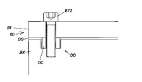
- a heat insulation means DD is provided between the connecting portion between the first vacuum pump P1 and the housing BX of the control circuit CC, specifically, between the cooling means 60 and the housing BX provided at the lower part of the first vacuum pump P1, the housing BX As means for preventing the occurrence of dew condensation in the interior, as shown in FIG. 6, a heat insulation means DD is provided.
- the housing BX is also cooled by heat conduction, and condensation may occur in the housing BX.
- the control circuit CC may malfunction or break down due to water droplets due to condensation, the heat insulating means DD prevents the occurrence of condensation by blocking such a heat conduction path.
- heat insulation means DD As a specific configuration example of the heat insulation means DD as described above, in the exhaust system S1 of FIG. 1, as shown in FIG. 6, heat insulation is provided between the water cooling plate 59 and the housing BX constituting the water cooling means 60. And a system in which a heat insulating collar (insulating collar) DC is installed around a bolt BT2 that fastens the water cooling plate 59 and the housing BX. Any one of the methods can be omitted as necessary. As a material of the heat insulating collar DC, stainless steel or ceramic can be adopted, but is not limited thereto. *
- the control circuit CC of at least one of the first vacuum pump P1 and the second vacuum pump P2 is accommodated in the casing BX, and the casing A structure in which BX is integrated with at least one of the vacuum pumps (P1 or P2) can be employed, and is not limited to the above example.
- a third vacuum pump P3 is further arranged and connected downstream of the second vacuum pump P2.
- a connection part C2 (second connection part) for connecting the second vacuum pump P2 and the third vacuum pump P3 is a pipe PL1 for connecting both the vacuum pumps P2, P3,
- the valve VL1 and the like provided in the middle of the pipe PL1 are included, and the gas discharged from the exhaust port 71 of the second vacuum pump P2 passes through such a pipe PL1 and the valve VL1 to the third vacuum. Transition to pump P3.
- the first gas condensing environment is that the environment inside the second vacuum pump P2 is included in the solid phase region above the vapor pressure curve VPC of the condensable gas flowing through the inside.
- the environment With respect to the setting of such an environment, for example, the inside of the second vacuum pump P2 is held at a predetermined temperature by the heat-retaining function of the second vacuum pump P2, and thereby the predetermined temperature is set inside the second vacuum pump P2. This can be achieved by the corresponding pressure exceeding the vapor pressure curve VPC of the condensable gas.
- the second gas condensing environment is the condensability in which the environment inside the connecting portion C2 connecting the second vacuum pump P2 and the third vacuum pump P3 flows through the inside. This is the environment included in the solid phase region above the gas vapor pressure curve VPC. Regarding the setting of such an environment, for example, the inside of the connection part C2 is maintained at a predetermined temperature by keeping the temperature of the connection part C2, so that the pressure corresponding to the predetermined temperature is maintained in the connection part C2. It can be realized by exceeding the vapor pressure curve VPC. *
- gas condensing is performed inside the second vacuum pump P2, specifically in a gas exhaust passage formed by a gap between the rotating body and the surrounding fixed portion. And the condensed components of the gas adhere to the gas exhaust passage.
- the condensed component of the adhering gas can be removed quickly and effectively by utilizing the mechanical structural characteristics of the second vacuum pump P2.
- the second vacuum pump P2 is composed of a volume transfer pump DP1 such as a Roots pump as described above, and the rotary body inside the pump is a fixed part around it or the other rotary body. And it is structured to rotate with a small gap. For this reason, when the thickness of the condensed component of the gas attached as described above becomes larger than the gap around the rotating body, the gas is surely removed in a form that is scraped off by the rotating body.
- the second pressure is set so as to exceed the vapor pressure curve VPC of the condensable gas in the vicinity of the exhaust port 71 of the second vacuum pump P2. It is preferable to set the temperature of the vacuum pump P2. *
- the second vacuum pump P2 is used. It is conceivable to attach a precipitate collection tank TK directly below the exhaust port 71 via a straight pipe type pipe PL2. According to this method, the condensed component of the gas scraped off as described above passes through the pipe PL2 and the valve VL2 in the middle thereof and falls into the precipitate collection tank TK and is collected.
- the trap TR1 or the inside of the trap TR or the inside of the storage tank is an environment included in the solid phase region above the vapor pressure curve VPC of the condensable gas flowing through the trap TR, Gas condensation occurs inside the trapping means TR such as a storage tank, and the condensed gas component can be trapped by the trapping means TR.
- the trap TR1 includes a pressure vessel 80, a plurality of plate-like members 81 (trap plates) installed in the pressure vessel 80, the inside of the pressure vessel 80, and the plate-like member.
- You may comprise so that the condensed gas component may adhere to the plate-shaped member 80 by condensing gas.
- the plate-like member 81 is installed in parallel with the gas flow. This is to prevent the gas flow from being obstructed by the plate-like member 81.
- the storage tank may be configured similarly to the trap TR1. *
- Maintenance of the trap TR1 may be performed by closing the manual valve VL3 and the electromagnetic valve VL1 provided in the middle of the pipe PL1 constituting the connection portion C2, opening the pressure vessel 80, and taking out and replacing the plate member 81.
- the valve VL3 is double installed so that the plate-like member 81 is taken out and replaced while the condensed component of the gas accumulated in the trap TR is sealed in the pressure vessel 80. May be. *
- the connecting part C1 is constituted by a pipe PL4, and gas moves from the first vacuum pump P1 toward the second vacuum pump P2 through the pipe PL4.
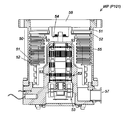
- the turbo molecular pump TP2 including the large-diameter exhaust port 57 shown in FIG. 10 can be adopted as the first vacuum pump P1. Since the basic configuration of the turbo molecular pump TP2 shown in FIG. 10 is the same as the configuration of the turbo molecular pump TP1 shown in FIG. 3, the same reference numerals are given to the same members, and the detailed description thereof is as follows. Omitted. *
- the second vacuum pump P2 (the positive displacement pump DP1)
- the suction ports 70 are rectangular, or a plurality of the suction ports 70 are arranged in a line.
- the piping PL4 in the exhaust system S2 of FIG. 8 it is preferable to employ, for example, the piping PL4 having the shape shown in FIG. *
- the exhaust system S2 in FIG. 8 is also provided with the second vacuum pump P2 in the vicinity of the first vacuum pump P1, so that the exhaust system S2 in FIG.
- the environment can be set so as to be an environment included in the gas phase region below the vapor pressure curve of the condensable gas flowing through the inside, and the same effect as the exhaust system S1 of FIG. 1 can be obtained.
- the L-shaped pipe PL4 is adopted as a specific configuration of the connecting part C1, but instead, the straight pipe type pipe PL5 shown in FIG. 9 is connected to the connecting part C1.
- the straight pipe type pipe PL5 is used in adopting the above-described “measures against gas condensation in the present invention”. It is considered that the pipe PL5 is more suitable.
- the vapor pressure curve diagram of FIG. 2 has been described as an example in which the condensable gas undergoes a phase change from gas to solid, but when the gas changes from gas to liquid, or from gas to liquid through solid Including the case of phase change, the same effect can be obtained.
Landscapes
- Engineering & Computer Science (AREA)
- Mechanical Engineering (AREA)
- General Engineering & Computer Science (AREA)
- Non-Positive Displacement Air Blowers (AREA)
- Compressors, Vaccum Pumps And Other Relevant Systems (AREA)
- Applications Or Details Of Rotary Compressors (AREA)
Abstract
Description
されるターボ分子ポンプTP1では、図3に示したように、ロータ54と回転翼51からなる回転体を磁気軸受53により非接触で支持し、この支持状態において、回転体とその周囲の固定部との隙間(具体的には回転翼51と固定翼52の隙間)を狭く保つように制御している。
捕捉手段TRで捕捉できる。
Claims (18)
- 少なくとも2つのポンプとして第1の真空ポンプおよび第2の真空ポンプを直列に接続し、これらの真空ポンプとその接続部を通じて、凝縮性ガスを含むガスを排気する排気システムにおいて、 前記第1の真空ポンプの近傍に前記第2の真空ポンプを設置することにより、前記接続部の内部の環境が、その内部を流れる前記凝縮性ガスの蒸気圧曲線より下の気相領域に含まれる環境となるように設定したこと を特徴とする排気システム。
- 前記第1の真空ポンプと前記第2の真空ポンプは連結して一体化されていること を特徴とする請求項1に記載の排気システム。
- 前記接続部に防振構造が設けられていること を特徴とする請求項1に記載の排気システム。
- 前記第1の真空ポンプは、前記第2の真空ポンプより上流に位置し、かつ、ターボ分子ポンプからなること を特徴とする請求項1に記載の排気システム。
- 前記ターボ分子ポンプは、回転翼と固定翼とで前記ガスを排気する翼排気機構を備え、ドラックポンプ機構を備えない構造になっていること を特徴とする請求項4に記載の排気システム。
- 前記接続部の内部の温度を上げることなくその内部の圧力を下げることにより、前記接続部の内部の環境が、その内部を流れる前記凝縮性ガスの前記蒸気圧曲線より下の前記気相領域に含まれる環境となるように設定したこと を特徴とする請求項4に記載の排気システム。
- 前記第2の真空ポンプは、前記第1の真空ポンプより下流に位置し、かつ、容積移送式ポンプからなること を特徴とする請求項1に記載の排気システム。
- 前記容積移送式ポンプは、そのポンプ内を加熱するためのヒータと、そのポンプ内の温度を測定する温度センサと、前記温度センサでの測定値を用いて前記ヒータの加熱温度を制御する温度制御回路とを備えること を特徴とする請求項7に記載の排気システム。
- 前記容積移送式ポンプは、インバータ回路を備え、前記インバータ回路によって回転速度の変更が可能であること を特徴とする請求項7に記載の排気システム。
- 前記容積移送式ポンプは、通常運転時の回転速度よりも低い回転速度での運転を可能とする低速運転機能を備えていること を特徴とする請求項7または請求項9に記載の排気システム。
- 前記第1の真空ポンプまたは前記第2の真空ポンプのうち、少なくとも、いずれか一方の真空ポンプの制御回路を筐体に収容し、その筐体を、少なくとも、いずれか一方の前記真空ポンプに連結して一体化した構造になっていること を特徴とする請求項2に記載の排気システム。
- 前記第1の真空ポンプまたは前記第2の真空ポンプと前記制御回路の前記筐体との連結部に、断熱手段が設けられていること を特徴とする請求項11に記載の排気システム。
- 前記第2の真空ポンプの下流に、第3の真空ポンプを配置し接続したこと を特徴とする請求項1に記載の排気システム。
- 前記第2の真空ポンプの内部の環境が、その内部を流れる前記凝縮性ガスの前記蒸気圧曲線より上の固相領域に含まれる環境となるように設定したこと を特徴とする請求項1に記載の排気システム。
- 前記第2の真空ポンプと前記第3の真空ポンプとを接続する第2の接続部の内部の環境が、その内部を流れる前記凝縮性ガスの前記蒸気圧曲線より上の固相領域に含まれる環境となるように設定したこと を特徴とする請求項13に記載の排気システム。
- 前記第2の真空ポンプと前記第3の真空ポンプとを接続する前記第2の接続部に、凝縮または凝固したガス成分を捕捉するトラップまたは貯蔵タンクを設けたこと を特徴とする請求項15に記載の排気システム。
- 請求項1から16に記載の排気システムを構成する真空ポンプ。
- 請求項17に記載の真空ポンプの構成部品。
Priority Applications (4)
| Application Number | Priority Date | Filing Date | Title |
|---|---|---|---|
| CN201680040293.3A CN107709773B (zh) | 2015-07-23 | 2016-07-01 | 排气系统 |
| EP16827586.5A EP3327286A4 (en) | 2015-07-23 | 2016-07-01 | Venting system |
| US15/743,185 US12276283B2 (en) | 2015-07-23 | 2016-07-01 | Integrated connector between first and second vacuum pumps creating a vapor phase region environment |
| KR1020177037449A KR102596221B1 (ko) | 2015-07-23 | 2016-07-01 | 배기 시스템 |
Applications Claiming Priority (2)
| Application Number | Priority Date | Filing Date | Title |
|---|---|---|---|
| JP2015145473A JP6616611B2 (ja) | 2015-07-23 | 2015-07-23 | 排気システム |
| JP2015-145473 | 2015-07-23 |
Publications (1)
| Publication Number | Publication Date |
|---|---|
| WO2017014022A1 true WO2017014022A1 (ja) | 2017-01-26 |
Family
ID=57834031
Family Applications (1)
| Application Number | Title | Priority Date | Filing Date |
|---|---|---|---|
| PCT/JP2016/069574 Ceased WO2017014022A1 (ja) | 2015-07-23 | 2016-07-01 | 排気システム |
Country Status (6)
| Country | Link |
|---|---|
| US (1) | US12276283B2 (ja) |
| EP (1) | EP3327286A4 (ja) |
| JP (1) | JP6616611B2 (ja) |
| KR (1) | KR102596221B1 (ja) |
| CN (1) | CN107709773B (ja) |
| WO (1) | WO2017014022A1 (ja) |
Cited By (2)
| Publication number | Priority date | Publication date | Assignee | Title |
|---|---|---|---|---|
| WO2021200022A1 (ja) * | 2020-03-31 | 2021-10-07 | エドワーズ株式会社 | 真空ポンプおよび真空ポンプの配管構造部 |
| JP2022514461A (ja) * | 2018-12-03 | 2022-02-14 | ファイファー バキユーム | ポンプユニット |
Families Citing this family (5)
| Publication number | Priority date | Publication date | Assignee | Title |
|---|---|---|---|---|
| JP7361640B2 (ja) * | 2020-03-09 | 2023-10-16 | エドワーズ株式会社 | 真空ポンプ |
| JP7427558B2 (ja) * | 2020-08-03 | 2024-02-05 | エドワーズ株式会社 | 真空排気系の洗浄装置 |
| CN113847244A (zh) * | 2021-10-14 | 2021-12-28 | 四川莱斯特真空科技有限公司 | 一体式涡轮螺杆组合泵 |
| JP2023125364A (ja) * | 2022-02-28 | 2023-09-07 | エドワーズ株式会社 | 真空排気システム |
| CN115263776B (zh) * | 2022-08-31 | 2025-09-30 | 上海华力微电子有限公司 | 一种涡轮分子泵用定子防尘组件 |
Citations (8)
| Publication number | Priority date | Publication date | Assignee | Title |
|---|---|---|---|---|
| JPS6346717Y2 (ja) * | 1983-07-30 | 1988-12-02 | ||
| JPH0419393B2 (ja) * | 1984-05-21 | 1992-03-30 | Hitachi Ltd | |
| JPH0612794U (ja) * | 1992-07-13 | 1994-02-18 | 株式会社大阪真空機器製作所 | 複合型真空ポンプの加熱装置 |
| JPH0784871B2 (ja) * | 1986-06-12 | 1995-09-13 | 株式会社日立製作所 | 真空排気装置 |
| JPH09219172A (ja) * | 1996-02-09 | 1997-08-19 | Ebara Corp | イオン注入装置の排気装置 |
| JPH09310696A (ja) * | 1996-03-21 | 1997-12-02 | Osaka Shinku Kiki Seisakusho:Kk | 分子ポンプ |
| JP2005120955A (ja) * | 2003-10-17 | 2005-05-12 | Ebara Corp | 真空排気装置 |
| WO2012046495A1 (ja) * | 2010-10-07 | 2012-04-12 | エドワーズ株式会社 | 真空ポンプ制御装置及び真空ポンプ |
Family Cites Families (31)
| Publication number | Priority date | Publication date | Assignee | Title |
|---|---|---|---|---|
| US4372155A (en) * | 1981-05-20 | 1983-02-08 | Ford Motor Company | Methods of monitoring a combustion system |
| JPS6028298A (ja) | 1983-07-27 | 1985-02-13 | 株式会社日立製作所 | 電子部品搭載装置 |
| US4862697A (en) * | 1986-03-13 | 1989-09-05 | Helix Technology Corporation | Cryopump with vibration isolation |
| DE3613344A1 (de) * | 1986-04-19 | 1987-10-22 | Pfeiffer Vakuumtechnik | Turbomolekular-vakuumpumpe fuer hoeheren druck |
| JPS62279282A (ja) * | 1986-05-27 | 1987-12-04 | Mitsubishi Electric Corp | タ−ボ分子ポンプ |
| JPH01277698A (ja) * | 1988-04-30 | 1989-11-08 | Nippon Ferrofluidics Kk | 複合型真空ポンプ |
| JP2538796B2 (ja) * | 1989-05-09 | 1996-10-02 | 株式会社東芝 | 真空排気装置および真空排気方法 |
| JPH02294574A (ja) * | 1989-05-10 | 1990-12-05 | Hitachi Ltd | 真空排気装置 |
| FR2656658B1 (fr) * | 1989-12-28 | 1993-01-29 | Cit Alcatel | Pompe a vide turbomoleculaire mixte, a deux arbres de rotation et a refoulement a la pression atmospherique. |
| KR950007378B1 (ko) * | 1990-04-06 | 1995-07-10 | 가부시끼 가이샤 히다찌 세이사꾸쇼 | 진공펌프 |
| JP2537696B2 (ja) * | 1990-09-21 | 1996-09-25 | 株式会社荏原製作所 | 多段真空ポンプ |
| JP2994740B2 (ja) * | 1990-11-30 | 1999-12-27 | 株式会社ユニフローズ | 脱気装置 |
| EP0541929A1 (en) | 1991-11-12 | 1993-05-19 | SAVANT INSTRUMENTS, Inc. | Gas pumping system with liquid elimination feature |
| JPH05272478A (ja) * | 1992-01-31 | 1993-10-19 | Matsushita Electric Ind Co Ltd | 真空ポンプ |
| JP3237210B2 (ja) | 1992-06-25 | 2001-12-10 | ソニー株式会社 | ディスク装置 |
| EP0626516B1 (de) * | 1993-04-15 | 1997-06-04 | KNF Neuberger GmbH | Schmiermittelfreie Vakuum-Pumpeinrichtung |
| DE19732808A1 (de) * | 1997-07-30 | 1999-02-04 | Knf Neuberger Gmbh | Verfahren zur Evakuierung der Sterilisationskammer einer Dampfsterilisationsvorrichtung sowie Dampfsterilisationsvorrichtung |
| US7077159B1 (en) * | 1998-12-23 | 2006-07-18 | Applied Materials, Inc. | Processing apparatus having integrated pumping system |
| US6193461B1 (en) * | 1999-02-02 | 2001-02-27 | Varian Inc. | Dual inlet vacuum pumps |
| DE10043783A1 (de) | 2000-09-06 | 2002-03-14 | Leybold Vakuum Gmbh | Verfahren und Vorrichtung zur Regelung des Vakuums in einer Kammer |
| JP2005042709A (ja) * | 2003-07-10 | 2005-02-17 | Ebara Corp | 真空ポンプ |
| FR2869369B1 (fr) * | 2004-04-21 | 2006-07-21 | Alcatel Sa | Pompe a vide multi-etagee, et installation de pompage comprenant une telle pompe |
| JP4703279B2 (ja) * | 2004-06-25 | 2011-06-15 | 株式会社大阪真空機器製作所 | 複合分子ポンプの断熱構造 |
| US20070020115A1 (en) * | 2005-07-01 | 2007-01-25 | The Boc Group, Inc. | Integrated pump apparatus for semiconductor processing |
| GB0605048D0 (en) * | 2006-03-14 | 2006-04-26 | Boc Group Plc | Apparatus for treating a gas stream |
| JP4702236B2 (ja) * | 2006-09-12 | 2011-06-15 | 株式会社豊田自動織機 | 真空ポンプの運転停止制御方法及び運転停止制御装置 |
| JP2008088912A (ja) * | 2006-10-03 | 2008-04-17 | Tohoku Univ | メカニカルポンプおよびその製造方法 |
| JP5719592B2 (ja) * | 2008-07-14 | 2015-05-20 | エドワーズ株式会社 | 真空ポンプ |
| JP6009193B2 (ja) * | 2012-03-30 | 2016-10-19 | 株式会社荏原製作所 | 真空排気装置 |
| JP2014029130A (ja) | 2012-07-31 | 2014-02-13 | Edwards Kk | 真空ポンプ |
| US9765789B2 (en) * | 2013-03-13 | 2017-09-19 | Agilent Technologies, Inc. | Pump testing for predicting lifetime and wear conditions |
-
2015
- 2015-07-23 JP JP2015145473A patent/JP6616611B2/ja active Active
-
2016
- 2016-07-01 KR KR1020177037449A patent/KR102596221B1/ko active Active
- 2016-07-01 WO PCT/JP2016/069574 patent/WO2017014022A1/ja not_active Ceased
- 2016-07-01 EP EP16827586.5A patent/EP3327286A4/en active Pending
- 2016-07-01 CN CN201680040293.3A patent/CN107709773B/zh active Active
- 2016-07-01 US US15/743,185 patent/US12276283B2/en active Active
Patent Citations (8)
| Publication number | Priority date | Publication date | Assignee | Title |
|---|---|---|---|---|
| JPS6346717Y2 (ja) * | 1983-07-30 | 1988-12-02 | ||
| JPH0419393B2 (ja) * | 1984-05-21 | 1992-03-30 | Hitachi Ltd | |
| JPH0784871B2 (ja) * | 1986-06-12 | 1995-09-13 | 株式会社日立製作所 | 真空排気装置 |
| JPH0612794U (ja) * | 1992-07-13 | 1994-02-18 | 株式会社大阪真空機器製作所 | 複合型真空ポンプの加熱装置 |
| JPH09219172A (ja) * | 1996-02-09 | 1997-08-19 | Ebara Corp | イオン注入装置の排気装置 |
| JPH09310696A (ja) * | 1996-03-21 | 1997-12-02 | Osaka Shinku Kiki Seisakusho:Kk | 分子ポンプ |
| JP2005120955A (ja) * | 2003-10-17 | 2005-05-12 | Ebara Corp | 真空排気装置 |
| WO2012046495A1 (ja) * | 2010-10-07 | 2012-04-12 | エドワーズ株式会社 | 真空ポンプ制御装置及び真空ポンプ |
Non-Patent Citations (1)
| Title |
|---|
| See also references of EP3327286A4 * |
Cited By (4)
| Publication number | Priority date | Publication date | Assignee | Title |
|---|---|---|---|---|
| JP2022514461A (ja) * | 2018-12-03 | 2022-02-14 | ファイファー バキユーム | ポンプユニット |
| WO2021200022A1 (ja) * | 2020-03-31 | 2021-10-07 | エドワーズ株式会社 | 真空ポンプおよび真空ポンプの配管構造部 |
| JP2021161917A (ja) * | 2020-03-31 | 2021-10-11 | エドワーズ株式会社 | 真空ポンプおよび真空ポンプの配管構造部 |
| JP7766998B2 (ja) | 2020-03-31 | 2025-11-11 | エドワーズ株式会社 | 真空ポンプ |
Also Published As
| Publication number | Publication date |
|---|---|
| EP3327286A1 (en) | 2018-05-30 |
| KR20180034338A (ko) | 2018-04-04 |
| JP6616611B2 (ja) | 2019-12-04 |
| CN107709773B (zh) | 2020-11-03 |
| US20190120236A1 (en) | 2019-04-25 |
| KR102596221B1 (ko) | 2023-11-01 |
| CN107709773A (zh) | 2018-02-16 |
| JP2017025793A (ja) | 2017-02-02 |
| US12276283B2 (en) | 2025-04-15 |
| EP3327286A4 (en) | 2019-03-13 |
Similar Documents
| Publication | Publication Date | Title |
|---|---|---|
| JP6616611B2 (ja) | 排気システム | |
| EP1553303B1 (en) | Apparatus for evacuating a plurality of vacuum chambers | |
| US8601792B2 (en) | Oil cooler having adjustable heat transfer effectiveness | |
| US10704555B2 (en) | Stator-side member and vacuum pump | |
| KR20160037837A (ko) | 진공 펌프 | |
| JP6101365B2 (ja) | 流量制御弁 | |
| EP3875769B1 (en) | Vacuum pump, and vacuum pump constituent component | |
| JP2007262906A (ja) | 2段式真空ポンプ | |
| KR101120887B1 (ko) | 펌프, 펌프 내의 로터와 스테이터 사이의 간극 제어 방법 및 컴퓨터 판독가능한 저장 매체 | |
| CN110863997A (zh) | 带内加热装置的磁悬浮分子泵 | |
| WO2016133013A1 (ja) | ストレーナ | |
| JP7619871B2 (ja) | ターボ分子ポンプ | |
| CN115917147B (zh) | 真空排气系统的清洗装置 | |
| JP2002285992A (ja) | 真空ポンプ装置 | |
| JP2014001643A (ja) | 真空ポンプ | |
| US20140248166A1 (en) | Pump | |
| US20140290910A1 (en) | Intake air cooling system | |
| US12268981B2 (en) | Motorized valve with washing filter extending from a bleed conduit inlet into valve duct | |
| JP6601446B2 (ja) | 排気管 | |
| JP7802729B2 (ja) | 真空排気システム、及び真空ポンプ | |
| JP7378447B2 (ja) | 真空ポンプおよび固定部品 | |
| JP2016133326A (ja) | 二重管構造の真空度推定システム、内燃機関、及び、二重管構造の真空度推定方法 | |
| WO2017109816A1 (ja) | 遠心式圧縮機 | |
| JP5570550B2 (ja) | クライオポンプ | |
| KR20120018576A (ko) | 흡기 매니폴드의 pcv 니플 결빙물 제거 구조체 |
Legal Events
| Date | Code | Title | Description |
|---|---|---|---|
| 121 | Ep: the epo has been informed by wipo that ep was designated in this application |
Ref document number: 16827586 Country of ref document: EP Kind code of ref document: A1 |
|
| ENP | Entry into the national phase |
Ref document number: 20177037449 Country of ref document: KR Kind code of ref document: A |
|
| NENP | Non-entry into the national phase |
Ref country code: DE |
|
| WWE | Wipo information: entry into national phase |
Ref document number: 2016827586 Country of ref document: EP |
|
| WWG | Wipo information: grant in national office |
Ref document number: 15743185 Country of ref document: US |