WO2017014114A1 - Dispositif de commande anticollision et procédé de commande anticollision - Google Patents
Dispositif de commande anticollision et procédé de commande anticollision Download PDFInfo
- Publication number
- WO2017014114A1 WO2017014114A1 PCT/JP2016/070616 JP2016070616W WO2017014114A1 WO 2017014114 A1 WO2017014114 A1 WO 2017014114A1 JP 2016070616 W JP2016070616 W JP 2016070616W WO 2017014114 A1 WO2017014114 A1 WO 2017014114A1
- Authority
- WO
- WIPO (PCT)
- Prior art keywords
- collision avoidance
- acceleration
- vehicle
- avoidance control
- control
- Prior art date
- Legal status (The legal status is an assumption and is not a legal conclusion. Google has not performed a legal analysis and makes no representation as to the accuracy of the status listed.)
- Ceased
Links
Images


Classifications
-
- B—PERFORMING OPERATIONS; TRANSPORTING
- B60—VEHICLES IN GENERAL
- B60R—VEHICLES, VEHICLE FITTINGS, OR VEHICLE PARTS, NOT OTHERWISE PROVIDED FOR
- B60R21/00—Arrangements or fittings on vehicles for protecting or preventing injuries to occupants or pedestrians in case of accidents or other traffic risks
-
- B—PERFORMING OPERATIONS; TRANSPORTING
- B60—VEHICLES IN GENERAL
- B60T—VEHICLE BRAKE CONTROL SYSTEMS OR PARTS THEREOF; BRAKE CONTROL SYSTEMS OR PARTS THEREOF, IN GENERAL; ARRANGEMENT OF BRAKING ELEMENTS ON VEHICLES IN GENERAL; PORTABLE DEVICES FOR PREVENTING UNWANTED MOVEMENT OF VEHICLES; VEHICLE MODIFICATIONS TO FACILITATE COOLING OF BRAKES
- B60T17/00—Component parts, details, or accessories of power brake systems not covered by groups B60T8/00, B60T13/00 or B60T15/00, or presenting other characteristic features
- B60T17/18—Safety devices; Monitoring
-
- B—PERFORMING OPERATIONS; TRANSPORTING
- B60—VEHICLES IN GENERAL
- B60T—VEHICLE BRAKE CONTROL SYSTEMS OR PARTS THEREOF; BRAKE CONTROL SYSTEMS OR PARTS THEREOF, IN GENERAL; ARRANGEMENT OF BRAKING ELEMENTS ON VEHICLES IN GENERAL; PORTABLE DEVICES FOR PREVENTING UNWANTED MOVEMENT OF VEHICLES; VEHICLE MODIFICATIONS TO FACILITATE COOLING OF BRAKES
- B60T7/00—Brake-action initiating means
- B60T7/12—Brake-action initiating means for automatic initiation; for initiation not subject to will of driver or passenger
-
- B—PERFORMING OPERATIONS; TRANSPORTING
- B60—VEHICLES IN GENERAL
- B60W—CONJOINT CONTROL OF VEHICLE SUB-UNITS OF DIFFERENT TYPE OR DIFFERENT FUNCTION; CONTROL SYSTEMS SPECIALLY ADAPTED FOR HYBRID VEHICLES; ROAD VEHICLE DRIVE CONTROL SYSTEMS FOR PURPOSES NOT RELATED TO THE CONTROL OF A PARTICULAR SUB-UNIT
- B60W30/00—Purposes of road vehicle drive control systems not related to the control of a particular sub-unit, e.g. of systems using conjoint control of vehicle sub-units
- B60W30/08—Active safety systems predicting or avoiding probable or impending collision or attempting to minimise its consequences
- B60W30/09—Taking automatic action to avoid collision, e.g. braking and steering
Definitions
- the present invention relates to a vehicle collision avoidance control device and a collision avoidance control method.
- one of the problems of the present invention is that smoother or safer, for example, when an operation of driving a vehicle is performed by the driver during the collision avoidance control or when the collision avoidance control device fails.
- Another object of the present invention is to obtain a vehicle collision avoidance control device capable of ending the collision avoidance control.
- a vehicle collision avoidance control device includes, for example, a collision avoidance control unit that controls at least a brake device so as to avoid a collision with an obstacle based on data acquired during traveling, and the collision avoidance control unit.
- a collision avoidance control unit that controls at least a brake device so as to avoid a collision with an obstacle based on data acquired during traveling
- the collision avoidance control unit When a driving operation is performed by the driver during the execution of the control, or when a failure occurs in which the control by the collision avoidance control unit cannot be normally performed, a plurality of end conditions with different control by the collision avoidance control unit
- the end determination unit that determines whether or not the state is satisfied, and the end determination unit determines that the end determination unit satisfies any one of the plurality of end conditions.
- An end control unit that controls at least one of the brake device and the drive device so as to achieve deceleration or acceleration corresponding to the conditions.
- the collision avoidance control device for example, when the operation of driving the vehicle is performed by the driver while the collision avoidance control is being executed, or when the collision avoidance control device fails
- the collision avoidance control can be terminated through a change in acceleration or deceleration set for each condition. Therefore, according to the vehicle collision avoidance control apparatus, for example, the collision avoidance control can be terminated more smoothly or safely depending on the situation.
- the end control unit is directed to the requested acceleration in a state that matches the stop condition when the driver performs a driving operation. At least one of the brake device and the drive device is controlled so that an increase in acceleration over time is limited. Therefore, according to the vehicle collision avoidance control device, for example, the collision avoidance control is terminated through a change in acceleration or deceleration of the vehicle corresponding to the stopped state, so that the collision avoidance can be performed more smoothly or safely. Control can be terminated.
- the end control unit is directed to the requested acceleration in a state that matches the end condition during movement when the driving operation is performed by the driver.
- at least one of the brake device and the drive device is controlled so that the acceleration increases at a higher increasing speed than when the stop condition matches the stopping condition. Therefore, according to the collision avoidance control device for a vehicle, for example, collision avoidance control is terminated through a change in acceleration or deceleration of the vehicle corresponding to the moving state, so that collision avoidance can be performed more smoothly or safely. Control can be terminated.
- the end control unit immediately ends the control by the collision avoidance control unit in a state that matches the end condition by the failure. Therefore, according to the collision avoidance control device for a vehicle, for example, the collision avoidance control is immediately terminated at the time of failure, so that it is possible to suppress an adverse effect caused by the failure.
- the computer controls at least the brake device so as to avoid a collision with an obstacle based on data acquired during traveling, and avoids a collision with the obstacle.
- the control it is determined whether it is in a state that satisfies any of a plurality of end conditions with different control of the brake device, and is in a state that satisfies any of the plurality of end conditions.
- at least one of the brake device and the drive device is controlled so that the deceleration or acceleration corresponding to the end condition is obtained.
- the collision avoidance control method for example, when the driver performs a driving operation, the amount of change in deceleration or acceleration per unit time is limited in a state that matches a stop condition during stopping. Thus, at least one of the brake device and the drive device is controlled. Therefore, according to the collision avoidance control method for a vehicle, for example, the collision avoidance control is completed through a change in the acceleration or deceleration of the vehicle corresponding to the stopped state, so that the collision avoidance can be performed more smoothly or more safely. Control can be terminated.
- FIG. 1 is an exemplary schematic diagram of a vehicle on which the collision avoidance control device for a vehicle according to the embodiment is mounted.
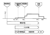
- FIG. 2 is an exemplary explanatory diagram illustrating transition of the control state by the vehicle collision avoidance control device of the embodiment.
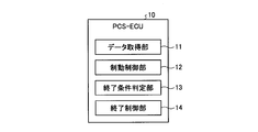
- FIG. 3 is an exemplary schematic block diagram of the vehicle collision avoidance control apparatus according to the embodiment.
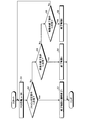
- FIG. 4 is an exemplary flowchart of termination control by the vehicle collision avoidance control apparatus according to the embodiment.
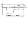
- FIG. 5 is an exemplary graph showing a change over time in the acceleration of the vehicle in a state that matches an end condition while the vehicle is stopped in the vehicle collision avoidance control apparatus of the embodiment.
- FIG. 1 is an exemplary schematic diagram of a vehicle on which the collision avoidance control device for a vehicle according to the embodiment is mounted.
- FIG. 2 is an exemplary explanatory diagram illustrating transition of the control state by the vehicle collision avoidance control device of the embodiment.
- FIG. 3 is an exemplary schematic block diagram of the vehicle collision avoidance control apparatus according to the
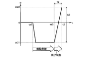
- FIG. 6 is an exemplary graph illustrating a change in acceleration of the vehicle over time in a state that matches a termination condition during movement of the vehicle in the collision avoidance control device for a vehicle according to the embodiment.
- FIG. 7 is an exemplary graph showing a change over time in the acceleration of the vehicle in a state that matches the termination condition at the time of failure in the vehicle collision avoidance control apparatus of the embodiment.
- each part of the vehicle 100 is controlled to avoid a collision with an obstacle ahead while the vehicle 100 is traveling forward is illustrated.
- FIG. 1 is an exemplary and schematic configuration diagram of the vehicle 100.
- the vehicle 100 includes an engine 51, a motor generator 62 (M / G), a brake device 41, and the like.
- Engine 51 and motor generator 62 cause acceleration of vehicle 100. Therefore, the engine 51 and the motor generator 62 can also be referred to as drive sources or drive devices.
- the vehicle 100 only needs to be equipped with at least one of the engine 51 and the motor generator 62 as a drive source. Further, the acceleration of the vehicle 100 is an increase over time of the speed toward the front of the vehicle 100 (time differentiation), and the deceleration of the vehicle 100 is a decrease over time of the speed toward the front of the vehicle 100 (time differentiation). ).
- the acceleration is also a negative deceleration
- the deceleration is also a negative acceleration. That is, the acceleration increases when the braking force or deceleration by the brake device 41 decreases, and the deceleration increases when the driving force or acceleration by the engine 51 or the motor generator 62 decreases.
- the vehicle 100 includes a PCS-ECU 10 (pre-crash safety electronic control unit).
- the PCS-ECU 10 detects that there is an obstacle ahead of the vehicle 100 based on the data acquired during traveling, the PCS-ECU 10 determines whether or not there is a possibility of a collision with the obstacle.
- the brake ECU 41 that controls the brake device 41, the engine 51, the motor generator 62, etc.
- the engine ECU 50 the M / GECU 60 (motor generator ECU), etc.
- the PCS-ECU 10 is an example of a collision avoidance control device.
- the PCS-ECU 10 instructs to control the acceleration or deceleration of the vehicle 100, that is, the driving force or the braking force, but the PCS-ECU 10 further instructs to control the steering of the vehicle 100. May be.
- the PCS-ECU 10 includes a control unit such as a CPU (central processing unit) and a controller, and a storage unit such as a ROM (read only memory), a RAM (random access memory), and a flash memory.
- the storage unit can store a program for operating the PCS-ECU 10, data used for arithmetic processing of the PCS-ECU 10, and the like.
- the vehicle 100 is equipped with a distance measuring device 21 and a camera 22.
- the distance measuring device 21 and the camera 22 are an example of an obstacle detection unit.
- the distance measuring device 21 is a device that wirelessly measures the distance to the obstacle without contact, and is, for example, a radar device or a sonar device.
- the PCS-ECU 10 acquires data indicating the distance from the obstacle from the distance measuring device 21.
- the data indicating the distance may be numerical data indicating the distance itself, or may be data having a value corresponding to the distance.
- the camera 22 is a digital camera incorporating an image sensor such as a CCD (charge coupled device) or a CIS (CMOS image sensor).
- the camera 22 can output moving image data at a predetermined frame rate.
- the PCS-ECU 10 may acquire data indicating an image captured by the camera 22 and acquire the distance to the obstacle using the image data.
- PCS-ECU 10 receives data indicating detection results from the various sensors from various sensors mounted on vehicle 100.
- the sensor mounted on the vehicle 100 may include a sensor that indicates a detection result of the state of the vehicle 100.
- Sensors indicating the detection result of the state of the vehicle 100 are, for example, a vehicle speed sensor, an acceleration sensor, a gyro sensor, and the like.
- the sensor mounted on the vehicle 100 may include a sensor that indicates a detection result of an operation amount or an operation request amount in an operation unit operated by a driver.
- the operation unit by the driver is, for example, an accelerator pedal, a brake pedal, a brake handle, a steering wheel, a switch, or the like.
- the sensor mounted on the vehicle 100 may include a sensor that indicates the detection result of the state of each device mounted on the vehicle 100.
- Devices mounted on the vehicle 100 are, for example, a brake device 41, an engine 51, a motor generator 62, an inverter 61 (IV), a steering system, a suspension system, and the like.
- the physical quantities detected by various sensors mounted on the vehicle 100 are, for example, distance, displacement, speed, acceleration, rotational speed, angle, angular velocity, angular acceleration, and the like.
- the PCS-ECU 10 may be input with numerical data indicating each physical quantity itself, or may be input with data corresponding to the magnitude of each physical quantity.
- the data input to the PCS-ECU 10 may be digital data, analog data such as non-numerical potentials, or data corresponding to on / off and stages instead of physical values. There may be.
- the PCS-ECU 10 calculates a predicted time to collide with an obstacle ahead, that is, TTC (time to collision) when performing collision avoidance control.
- TTC time to collision
- the TTC may be calculated in consideration of the relative acceleration of the obstacle, the deceleration of the vehicle 100, and the like. For example, the PCS-ECU 10 can determine that there is a possibility of a collision when the TTC is equal to or less than a predetermined value.
- the PCS-ECU 10 calculates the acceleration or deceleration of the vehicle 100 when performing collision avoidance control.
- the distribution ECU 30 calculates the share of the acceleration or deceleration set by the PCS-ECU 10 by the brake device 41, the engine 51, and the motor generator 62.
- the share ratio varies depending on the situation of the vehicle 100, for example.
- Distribution ECU 30 transmits data indicating acceleration or deceleration shared by brake ECU 40, engine ECU 50, and motor generator ECU 60 to each other.
- the brake ECU 40 controls the brake device 41 so that the acceleration or deceleration set by the PCS-ECU 10 can be obtained.
- the engine ECU 50 controls the engine 51 so that the acceleration or deceleration set by the PCS-ECU 10 can be obtained.
- motor generator ECU 60 controls inverter 61 so that motor generator 62 operates so that the acceleration or deceleration set by PCS-ECU 10 can be obtained.
- the brake ECU 40 can control the stop lamp 42 provided at the rear end of the vehicle 100 to light up.
- the lighting of the stop lamp 42 can be an alarm display for the surroundings of the vehicle 100, for example, the following vehicle.
- meter ECU70 can control the meter 71 provided in the instrument panel etc. so that a warning display may be output.
- the display output of the meter 71 can be an alarm display for the driver and passengers in the passenger compartment.
- the stop lamp 42 and the meter 71 can also be referred to as an alarm output device, an output device, an alarm device, a display output device, or the like.
- an audio output can be output from an audio output device (not shown).
- the audio output device is, for example, a speaker or a buzzer, and can also be called an alarm output device, an output device, an alarm device, or the like.
- FIG. 2 shows an example of the transition of the control state in the automatic collision avoidance control when the driver does not perform the brake operation.
- the horizontal axis represents time t
- the vertical axis represents deceleration
- ⁇ represents acceleration.
- the vertical axis in FIG. 2 is a required value for acceleration or deceleration.
- the PCS-ECU 10 calculates TTC at predetermined time intervals based on data acquired while the vehicle 100 is traveling, and starts collision avoidance control or performs collision avoidance control according to this TTC value. To the next stage, or the collision avoidance control is terminated. That is, the PCS-ECU 10 monitors the situation related to collision avoidance based on the TTC.
- the PCS-ECU 10 starts an alarm operation by the meter 71 or a speaker.
- the PCS-ECU 10 gives the brake ECU 40 an operation command that causes a slight deceleration of the vehicle 100 for a certain period of time, so that the brake ECU 40 drives a pump (not shown) of the brake device 41, and Clear the gap between the brake pads and the rotor, i.e. the brake disc or drum.
- This operation can also be referred to as prefill (PF).
- PF prefill
- the PCS-ECU 10 instructs the brake ECU 40 to perform preliminary braking for a certain period. Specifically, the PCS-ECU 10 transmits an instruction signal to the brake ECU 40 so that the stop lamp 42 is lit. Further, for example, the PCS-ECU 10 instructs the brake ECU 40 to obtain the minimum necessary deceleration (braking force) accompanying the lighting of the stop lamp 42, and the brake ECU 40 controls the brake device 41 based on the instruction. .
- the main purpose of the preliminary braking is to turn on the stop lamp 42, but a required deceleration that makes the driver of the rear vehicle aware of the deceleration operation may be obtained.
- the PCS-ECU 10 instructs the brake ECU 40 to start braking control for the purpose of avoiding a collision. Specifically, the PCS-ECU 10 instructs the brake ECU 40 to change the speed of the vehicle 100 at a required deceleration, that is, to obtain a required braking force, and the brake ECU 40 determines a brake device based on the instruction. 41 is controlled. In the braking control, the deceleration (braking force) may increase stepwise. The deceleration in the braking control is larger than the prefill and preliminary braking decelerations.
- the PCS-ECU 10 instructs the brake ECU 40 to maintain the stopped state for a predetermined period, and the brake ECU 40 controls the brake device 41 based on the instruction. To do.
- This operation can also be referred to as a brake hold (BH).
- the distribution ECU 30 can share the braking force with the motor generator 62 and the engine 51 according to the situation.
- the PCS-ECU 10 can end the above-described collision avoidance control by an operation of an accelerator pedal or a steering wheel by the driver, that is, an acceleration request operation, a steering operation, or the like.
- the PCS-ECU 10 includes a data acquisition unit 11, a braking control unit 12, an end condition determination unit 13, an end control unit 14 and the like as illustrated in FIG.
- operations for canceling the collision avoidance control such as an acceleration request operation and a steering operation, are simply referred to as a release operation below.
- the PCS-ECU 10 may be an independent ECU, or may be incorporated in an ECU of any system mounted on the vehicle.
- the PCS-ECU 10 can execute processes in accordance with installed and loaded programs to realize each function. That is, by executing the process according to the program, the PCS-ECU 10 can function as the data acquisition unit 11, the braking control unit 12, the end condition determination unit 13, the end control unit 14, and the like. Note that at least some of the functions of the above-described units may be realized by hardware.
- the data acquisition unit 11 can acquire data used for termination control.
- the data used for the end control is, for example, data indicating the operation amount of the acceleration request, data indicating the operation amount of the steering, data indicating the vehicle speed, data based on the fail determination, and the like.
- the data for fail determination is data indicating that the control by the PCS-ECU 10 has become unreliable, for example, data indicating failure of various sensors, failure of the motor or solenoid of the brake device 41, and the like. It is.
- the braking control unit 12 executes the PCS operation of FIG. 2, that is, the above-described prefill, preliminary braking, braking control, and brake hold.
- the braking control unit 12 is an example of a collision avoidance control unit.
- the end condition determination unit 13 determines whether or not the end condition determination unit 13 satisfies any one of a plurality of end conditions controlled by the braking control unit 12.
- the end conditions are the following (1) to (3).
- the vehicle 100 is moving, that is, during the PCS operation, specifically, prefill, standby.
- a predetermined amount of release operation is performed in the state of braking or braking control
- the termination condition determination unit 13 determines termination at predetermined time intervals. Running.
- the end condition determination unit 13 is an example of an end determination unit.
- (1) may also be referred to as a stop condition during stopping.
- (2) may also be referred to as a moving end condition.
- (3) can also be referred to as a failure determination condition.
- the predetermined amount of the release operation of (1) and (2) can be set for each of (1) and (2). Further, the predetermined amount of the releasing operation (2) may be set to a different value depending on the speed of the vehicle 100.
- the brake control device 14 When it is determined by the end condition determining unit 13 that the end control unit 14 is in a state satisfying any one of the plurality of end conditions, the brake control device 14 is configured so that the deceleration or acceleration corresponding to the end condition is obtained. 41, at least one of the engine 51 and the motor generator 62 is controlled.
- FIG. 4 shows an example of an end control procedure according to the present embodiment.
- S1 PCS operation or BH (S1)
- the end control unit 14 executes end control 1 corresponding to the stop condition during stopping (S4).
- FIG. 5 exemplifies the change with time of acceleration ⁇ in the end control 1 when the vehicle is in a state that matches the stop condition at the time td1 in FIG. 5 slightly after the time te1 in FIG.
- the acceleration ⁇ 11 is, for example, an acceleration generated in the vehicle 100 in a state where the driver does not perform the acceleration requesting operation, that is, an acceleration that causes the vehicle 100 to cause a creep phenomenon.
- the increase rate of the acceleration ⁇ can also be referred to as increment, inclination, change with time, increase rate per unit time, acceleration time derivative, jerk, jerk, and the like.
- An increase in acceleration corresponds to a decrease in deceleration, an increase in driving force, a decrease in braking force, and the like.
- the increase rate of the acceleration ⁇ in the increase interval of the acceleration ⁇ is not necessarily constant, and may vary somewhat.
- the end control unit 14 linearly increases the acceleration ⁇ from ⁇ 11 to ⁇ 12 from time t11 to time t12.
- the increasing speed of the acceleration ⁇ in this section is A1 / T1.
- the increase rate A1 / T1 of the acceleration ⁇ is set to a value lower than the increase rate of the acceleration ⁇ between the time td1 and the time t11.
- the end control unit 14 selects a smaller one of the driver's requested acceleration and the acceleration ⁇ limited by the increasing speed A1 / T1 in the section from the time t11 to the time t12. )I do. That is, when the driver's required acceleration is smaller than the acceleration ⁇ due to the increased speed A1 / T1, the driver's required acceleration is selected, and when the driver's required acceleration is larger than the acceleration ⁇ due to the increased speed A1 / T1.
- the acceleration ⁇ with the increasing speed A1 / T1 is selected.
- the value of the increasing speed A1 / T1, that is, the values of ⁇ 11, ⁇ 12, t11, and t12 can be set in advance so as to prevent the vehicle from suddenly jumping out.
- the increasing speed A1 / T1 can be variably set according to the distance from the obstacle, the steering of the driver, and the like.
- the increase speed A1 / T1 may be set to be larger when the distance to the obstacle is smaller than the distance from the obstacle (for example, by decreasing T1).
- Such an end control 1 suppresses the vehicle 100 from suddenly starting from the time of stopping.
- the vehicle 100 when the vehicle is stopped or stopped, the vehicle 100 may not be completely stopped, and may be in a state of a predetermined speed or less, for example, 10 km / h or less.
- FIG. 6 illustrates the change over time of the acceleration ⁇ in the end control 2 when the moving end condition is met at the time td2 in FIG. 6 before the time te1 in FIG.
- the end control unit 14 linearly increases the acceleration ⁇ until it reaches ⁇ 22 at time t2.
- the increasing speed of the acceleration ⁇ in this section is A2 / T2.
- the increase rate A2 / T2 of the acceleration ⁇ is set to a value higher than the increase rate A1 / T1 of the acceleration ⁇ in the section where the acceleration ⁇ increases from ⁇ 11 to ⁇ 12 or the required acceleration in the end control 1.
- the end control unit 14 selects a smaller one of the driver's requested acceleration and the acceleration ⁇ limited by the increase speed A2 / T2 in the section from the time td2 to the time t2. )I do.
- the value of the increase speed A2 / T2, that is, the values of ⁇ 22 and t2 can be set in consideration of both reflection of the driver's operation and ensuring of vehicle stability at the time of release. Further, the increase speed A2 / T2 can be variably set according to the distance to the obstacle, the driver's steering, the driver's acceleration operation, and the like. As an example, when the depression amount (operation amount) of the driver's accelerator pedal is large or when the depression speed (operation speed) is steep, the increase speed A2 / T2 is larger than that when it is not. It may be set as follows.
- FIG. 7 illustrates the change with time of the acceleration ⁇ in the end control 3 in a case where the failure determination condition is met at time td3 in FIG. 7 before time te1 in FIG.
- the termination control unit 14 immediately terminates the braking control. That is, in other words, the braking control unit 12 immediately ends the braking control.
- the end control unit 14 uses the end condition determination unit 13 to select one of a plurality of end conditions, that is, the stop condition during stopping, the end condition during movement, and the fail determination condition.
- the brake device 41 and the drive device that is, the engine 51 and the motor generator 62 is controlled so as to achieve the deceleration or acceleration corresponding to the end condition. Therefore, according to the present embodiment, the collision avoidance control is terminated through a change in acceleration or deceleration set for each of a plurality of termination conditions. Therefore, for example, the collision avoidance control can be terminated more smoothly or safely depending on the situation.
- the end control unit 14 in a state that matches the stop condition during stopping, causes the brake device 41, so that the increase in acceleration toward the requested acceleration is limited. At least one of the engine 51 and the motor generator 62 is controlled. Therefore, according to the present embodiment, the collision avoidance control is terminated after a change in the acceleration or deceleration of the vehicle corresponding to the stopped state of the vehicle 100, specifically, for example, a relatively moderate increase in acceleration. Therefore, the collision avoidance control can be finished more smoothly or safely.
- the end control unit 14 in a state that matches the moving end condition, increases the acceleration toward the requested acceleration higher than when the acceleration matches the stopping end condition. At least one of the brake device 41, the engine 51, and the motor generator 62 is controlled so as to increase. Therefore, according to the present embodiment, for example, the collision avoidance control is performed through a change in the acceleration or deceleration of the vehicle corresponding to the moving state of the vehicle 100, specifically, for example, through a relatively sudden increase in acceleration. Therefore, the collision avoidance control can be completed more smoothly or safely.
- the end control unit 14 immediately ends the control by the brake control unit 12 (collision avoidance control unit) in a state that matches the end condition by the failure. Therefore, according to the present embodiment, for example, the collision avoidance control is immediately terminated at the time of a failure, so that it is possible to suppress an adverse effect due to the failure.
Landscapes
- Engineering & Computer Science (AREA)
- Mechanical Engineering (AREA)
- Transportation (AREA)
- Automation & Control Theory (AREA)
- Regulating Braking Force (AREA)
- Valves And Accessory Devices For Braking Systems (AREA)
- Control Of Driving Devices And Active Controlling Of Vehicle (AREA)
Abstract
La présente invention concerne un dispositif de commande anticollision est pourvu, par exemple : d'une partie de commande anticollision; d'une partie de détermination de fin permettant de déterminer, lorsqu'une opération de conduite est effectuée par le conducteur alors que la commande est exécutée par la partie de commande anticollision ou lorsque une défaillance qui désactive une commande normale par la partie de commande anticollisionest survenue, laquelle parmi plusieurs conditions différentes pour mettre fin à la commande par la partie de commande anticollision est satisfaite par l'état résultant; et d'une partie de commande de fin pour commander, lorsque l'état est déterminé comme satisfaisant à l'une des multiples conditions de fin par une partie de détermination de fin, un dispositif de freinage et/ou un dispositif d'entraînement de manière à obtenir une décélération ou une accélération correspondant à la condition de fin.
Applications Claiming Priority (2)
| Application Number | Priority Date | Filing Date | Title |
|---|---|---|---|
| JP2015143479A JP2017024496A (ja) | 2015-07-17 | 2015-07-17 | 車両の衝突回避制御装置および衝突回避制御方法 |
| JP2015-143479 | 2015-07-17 |
Publications (1)
| Publication Number | Publication Date |
|---|---|
| WO2017014114A1 true WO2017014114A1 (fr) | 2017-01-26 |
Family
ID=57834929
Family Applications (1)
| Application Number | Title | Priority Date | Filing Date |
|---|---|---|---|
| PCT/JP2016/070616 Ceased WO2017014114A1 (fr) | 2015-07-17 | 2016-07-12 | Dispositif de commande anticollision et procédé de commande anticollision |
Country Status (2)
| Country | Link |
|---|---|
| JP (1) | JP2017024496A (fr) |
| WO (1) | WO2017014114A1 (fr) |
Families Citing this family (1)
| Publication number | Priority date | Publication date | Assignee | Title |
|---|---|---|---|---|
| JP7259356B2 (ja) * | 2019-01-28 | 2023-04-18 | スズキ株式会社 | 制御装置及び電動車両 |
Citations (3)
| Publication number | Priority date | Publication date | Assignee | Title |
|---|---|---|---|---|
| JPH05306638A (ja) * | 1992-03-27 | 1993-11-19 | Mazda Motor Corp | 車両の自動制動装置 |
| JP2009262700A (ja) * | 2008-04-23 | 2009-11-12 | Fuji Heavy Ind Ltd | 自動制動制御装置 |
| JP2015047954A (ja) * | 2013-08-30 | 2015-03-16 | トヨタ自動車株式会社 | 運転支援装置 |
-
2015
- 2015-07-17 JP JP2015143479A patent/JP2017024496A/ja active Pending
-
2016
- 2016-07-12 WO PCT/JP2016/070616 patent/WO2017014114A1/fr not_active Ceased
Patent Citations (3)
| Publication number | Priority date | Publication date | Assignee | Title |
|---|---|---|---|---|
| JPH05306638A (ja) * | 1992-03-27 | 1993-11-19 | Mazda Motor Corp | 車両の自動制動装置 |
| JP2009262700A (ja) * | 2008-04-23 | 2009-11-12 | Fuji Heavy Ind Ltd | 自動制動制御装置 |
| JP2015047954A (ja) * | 2013-08-30 | 2015-03-16 | トヨタ自動車株式会社 | 運転支援装置 |
Also Published As
| Publication number | Publication date |
|---|---|
| JP2017024496A (ja) | 2017-02-02 |
Similar Documents
| Publication | Publication Date | Title |
|---|---|---|
| JP6347448B2 (ja) | 車両の衝突回避制御装置および衝突回避制御方法 | |
| CN107848501B (zh) | 车辆的碰撞避免控制装置以及碰撞避免控制方法 | |
| CN105835819B (zh) | 车辆制动控制装置 | |
| US10065637B2 (en) | Method for avoiding a collision of a vehicle with an object | |
| CN104220306B (zh) | 避免碰撞支援装置 | |
| US20080312834A1 (en) | Vehicle-use collision mitigation apparatus | |
| JP6347447B2 (ja) | 車両の衝突回避制御装置および衝突回避制御方法 | |
| WO2016084968A1 (fr) | Dispositif anticollision | |
| WO2017014112A1 (fr) | Dispositif de commande d'évitement de collision pour véhicule, et procédé de commande d'évitement de collision | |
| JP5842740B2 (ja) | 車両の走行支援装置 | |
| JP5333604B2 (ja) | ブレーキ制御装置及びブレーキ制御方法 | |
| WO2017014114A1 (fr) | Dispositif de commande anticollision et procédé de commande anticollision | |
| JP2015047980A (ja) | ブレーキ制御装置 | |
| JP2016094112A (ja) | 車両の走行制御装置 | |
| RU2828924C1 (ru) | Способ и устройство для своевременного инициирования процесса автоматического аварийного торможения и управления продольным движением транспортного средства | |
| JP2025169614A (ja) | 車両制御装置 | |
| CN121375710A (zh) | 制动力调整方法、装置、存储介质、控制器及车辆 |
Legal Events
| Date | Code | Title | Description |
|---|---|---|---|
| 121 | Ep: the epo has been informed by wipo that ep was designated in this application |
Ref document number: 16827674 Country of ref document: EP Kind code of ref document: A1 |
|
| NENP | Non-entry into the national phase |
Ref country code: DE |
|
| 122 | Ep: pct application non-entry in european phase |
Ref document number: 16827674 Country of ref document: EP Kind code of ref document: A1 |