WO2017017930A1 - Batterie enroulée - Google Patents
Batterie enroulée Download PDFInfo
- Publication number
- WO2017017930A1 WO2017017930A1 PCT/JP2016/003387 JP2016003387W WO2017017930A1 WO 2017017930 A1 WO2017017930 A1 WO 2017017930A1 JP 2016003387 W JP2016003387 W JP 2016003387W WO 2017017930 A1 WO2017017930 A1 WO 2017017930A1
- Authority
- WO
- WIPO (PCT)
- Prior art keywords
- electrode
- battery case
- cylindrical portion
- battery
- cap
- Prior art date
- Legal status (The legal status is an assumption and is not a legal conclusion. Google has not performed a legal analysis and makes no representation as to the accuracy of the status listed.)
- Ceased
Links
Images


Classifications
-
- H—ELECTRICITY
- H01—ELECTRIC ELEMENTS
- H01M—PROCESSES OR MEANS, e.g. BATTERIES, FOR THE DIRECT CONVERSION OF CHEMICAL ENERGY INTO ELECTRICAL ENERGY
- H01M10/00—Secondary cells; Manufacture thereof
- H01M10/05—Accumulators with non-aqueous electrolyte
- H01M10/058—Construction or manufacture
- H01M10/0587—Construction or manufacture of accumulators having only wound construction elements, i.e. wound positive electrodes, wound negative electrodes and wound separators
-
- H—ELECTRICITY
- H01—ELECTRIC ELEMENTS
- H01M—PROCESSES OR MEANS, e.g. BATTERIES, FOR THE DIRECT CONVERSION OF CHEMICAL ENERGY INTO ELECTRICAL ENERGY
- H01M10/00—Secondary cells; Manufacture thereof
- H01M10/05—Accumulators with non-aqueous electrolyte
- H01M10/052—Li-accumulators
- H01M10/0525—Rocking-chair batteries, i.e. batteries with lithium insertion or intercalation in both electrodes; Lithium-ion batteries
-
- H—ELECTRICITY
- H01—ELECTRIC ELEMENTS
- H01M—PROCESSES OR MEANS, e.g. BATTERIES, FOR THE DIRECT CONVERSION OF CHEMICAL ENERGY INTO ELECTRICAL ENERGY
- H01M50/00—Constructional details or processes of manufacture of the non-active parts of electrochemical cells other than fuel cells, e.g. hybrid cells
- H01M50/10—Primary casings; Jackets or wrappings
- H01M50/102—Primary casings; Jackets or wrappings characterised by their shape or physical structure
- H01M50/107—Primary casings; Jackets or wrappings characterised by their shape or physical structure having curved cross-section, e.g. round or elliptic
-
- H—ELECTRICITY
- H01—ELECTRIC ELEMENTS
- H01M—PROCESSES OR MEANS, e.g. BATTERIES, FOR THE DIRECT CONVERSION OF CHEMICAL ENERGY INTO ELECTRICAL ENERGY
- H01M50/00—Constructional details or processes of manufacture of the non-active parts of electrochemical cells other than fuel cells, e.g. hybrid cells
- H01M50/10—Primary casings; Jackets or wrappings
- H01M50/147—Lids or covers
- H01M50/148—Lids or covers characterised by their shape
- H01M50/152—Lids or covers characterised by their shape for cells having curved cross-section, e.g. round or elliptic
-
- H—ELECTRICITY
- H01—ELECTRIC ELEMENTS
- H01M—PROCESSES OR MEANS, e.g. BATTERIES, FOR THE DIRECT CONVERSION OF CHEMICAL ENERGY INTO ELECTRICAL ENERGY
- H01M50/00—Constructional details or processes of manufacture of the non-active parts of electrochemical cells other than fuel cells, e.g. hybrid cells
- H01M50/10—Primary casings; Jackets or wrappings
- H01M50/147—Lids or covers
- H01M50/166—Lids or covers characterised by the methods of assembling casings with lids
- H01M50/171—Lids or covers characterised by the methods of assembling casings with lids using adhesives or sealing agents
-
- H—ELECTRICITY
- H01—ELECTRIC ELEMENTS
- H01M—PROCESSES OR MEANS, e.g. BATTERIES, FOR THE DIRECT CONVERSION OF CHEMICAL ENERGY INTO ELECTRICAL ENERGY
- H01M50/00—Constructional details or processes of manufacture of the non-active parts of electrochemical cells other than fuel cells, e.g. hybrid cells
- H01M50/10—Primary casings; Jackets or wrappings
- H01M50/183—Sealing members
- H01M50/184—Sealing members characterised by their shape or structure
-
- H—ELECTRICITY
- H01—ELECTRIC ELEMENTS
- H01M—PROCESSES OR MEANS, e.g. BATTERIES, FOR THE DIRECT CONVERSION OF CHEMICAL ENERGY INTO ELECTRICAL ENERGY
- H01M50/00—Constructional details or processes of manufacture of the non-active parts of electrochemical cells other than fuel cells, e.g. hybrid cells
- H01M50/10—Primary casings; Jackets or wrappings
- H01M50/183—Sealing members
- H01M50/186—Sealing members characterised by the disposition of the sealing members
- H01M50/188—Sealing members characterised by the disposition of the sealing members the sealing members being arranged between the lid and terminal
-
- Y—GENERAL TAGGING OF NEW TECHNOLOGICAL DEVELOPMENTS; GENERAL TAGGING OF CROSS-SECTIONAL TECHNOLOGIES SPANNING OVER SEVERAL SECTIONS OF THE IPC; TECHNICAL SUBJECTS COVERED BY FORMER USPC CROSS-REFERENCE ART COLLECTIONS [XRACs] AND DIGESTS
- Y02—TECHNOLOGIES OR APPLICATIONS FOR MITIGATION OR ADAPTATION AGAINST CLIMATE CHANGE
- Y02E—REDUCTION OF GREENHOUSE GAS [GHG] EMISSIONS, RELATED TO ENERGY GENERATION, TRANSMISSION OR DISTRIBUTION
- Y02E60/00—Enabling technologies; Technologies with a potential or indirect contribution to GHG emissions mitigation
- Y02E60/10—Energy storage using batteries
-
- Y—GENERAL TAGGING OF NEW TECHNOLOGICAL DEVELOPMENTS; GENERAL TAGGING OF CROSS-SECTIONAL TECHNOLOGIES SPANNING OVER SEVERAL SECTIONS OF THE IPC; TECHNICAL SUBJECTS COVERED BY FORMER USPC CROSS-REFERENCE ART COLLECTIONS [XRACs] AND DIGESTS
- Y02—TECHNOLOGIES OR APPLICATIONS FOR MITIGATION OR ADAPTATION AGAINST CLIMATE CHANGE
- Y02P—CLIMATE CHANGE MITIGATION TECHNOLOGIES IN THE PRODUCTION OR PROCESSING OF GOODS
- Y02P70/00—Climate change mitigation technologies in the production process for final industrial or consumer products
- Y02P70/50—Manufacturing or production processes characterised by the final manufactured product
Definitions
- the present invention relates to a battery including a wound electrode group, and more particularly to a wound battery having a battery case with a small outer diameter.
- Patent Document 1 in a battery including a small cylindrical metal can, a wound electrode group housed in the metal can, and a sealing member that seals the opening of the metal can, in order to suppress an internal short circuit
- a ring-shaped insulating member is disposed between the end face of the electrode group and the sealing member.
- Patent Document 2 a plate-like insulating ring is put on the end face of the electrode group.
- an independent insulating member is disposed between the electrode group and the sealing member.
- the operation of disposing such an insulating member in the battery case requires caution as the battery is downsized. For example, if the insulating member is inserted obliquely in the battery case, the insulating member may be damaged when the vicinity of the opening of the battery case is processed. At that time, a load is also applied to the end face of the electrode group, and the electrode group may be damaged. When the dimensions and processing accuracy of the insulating member vary, it becomes more difficult to insert the insulating member into the battery case. In addition, when vibration is applied to the battery when the battery is used, there is a concern that the insulating member and the electrode group collide and the electrode group is damaged.
- one aspect of the present disclosure includes a battery case having an opening, a power generation element housed in the battery case, a cap that closes the opening of the battery case, and a gasket that insulates the battery case and the cap.
- the power generation element includes a first electrode, a second electrode having a polarity different from that of the first electrode, a separator interposed between the first electrode and the second electrode, and an electrolyte.
- the first electrode and the second electrode are wound through a separator to form an electrode group, the first electrode and the cap are connected by the first current collecting lead, and the second electrode and the battery case Are connected by the second current collecting lead.
- an annular groove is formed so as to reduce the diameter of the battery case, and the gasket includes a portion from the groove to the end of the battery case, a peripheral edge of the cap, An annular seal portion interposed between the cylindrical portion and a cylindrical portion that is integrated with the seal portion and coaxial with the seal portion and disposed closer to the electrode group than the seal portion, and the first current collecting lead is
- the present invention relates to a wound battery that is connected to a cap through a hollow portion of a cylindrical portion.
- the manufacturing process of the wound battery can be simplified and reduced in cost, and the defect rate at the time of manufacturing the battery can be reduced.
- the vibration resistance of the battery can be increased.
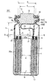
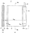
- FIG. 1 is a longitudinal sectional view of a cylindrical wound battery according to an embodiment of the present invention.
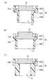
- FIG. 2 is a view showing variations of the gasket.
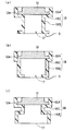
- FIG. 3 is a view showing another variation of the gasket.
- 4A and 4B are views showing a gasket in which the seal portion and the cylindrical portion are partially connected.
- FIG. 4A is a top view of the gasket in which the seal portion and the cylindrical portion are partially connected
- FIG. 4B is a front view.
- It is. 5A and 5B are diagrams schematically showing the first electrode, wherein FIG. 5A is a plan view schematically showing the first electrode, and FIG. 5B is a sectional view taken along the line IVb-IVb.
- FIG. 5A is a plan view schematically showing the first electrode
- FIG. 5B is a sectional view taken along the line IVb-IVb.
- FIG. 5A is a plan view schematically showing the first electrode
- FIG. 5B is a sectional view taken along the
- FIG. 6 is a diagram schematically showing another first electrode, (a) is a plan view schematically showing another first electrode, and (b) is a cross-sectional view (b) taken along the line Vb-Vb. .
- FIG. 7 schematically shows the second electrode, (a) is a plan view schematically showing the second electrode, and (b) is a sectional view taken along the line VIb-VIb.
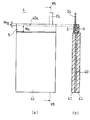
- FIG. 8 is a plan view schematically showing the configuration of the electrode group before winding.
- a wound battery according to the present disclosure includes a battery case having an opening, a power generation element housed in the battery case, a cap that closes the opening of the battery case, and a gasket that insulates the battery case and the cap.
- the power generation element includes a first electrode, a second electrode having a polarity different from that of the first electrode, a separator interposed between the first electrode and the second electrode, and an electrolyte.
- the first electrode and the second electrode are wound through a separator to form an electrode group.
- the electrode group is a columnar body having a first end face and a second end face opposite to the first end face.
- the end surface disposed on the opening side of the battery case is referred to as a first end surface
- the end surface disposed on the opposite side is referred to as a second end surface
- the first electrode usually includes a first current collector sheet and a first active material layer formed on the surface of the first current collector sheet.
- the second electrode usually includes a second current collector sheet and a second active material layer formed on the surface of the second current collector sheet.
- the first electrode is connected to a cap having conductivity by a first current collecting lead.
- the second electrode is connected to a conductive battery case by a second current collecting lead.
- An annular groove is formed in the vicinity of the end forming the opening of the battery case so as to reduce the diameter of the battery case.
- the groove serves to position the cap.
- the gasket includes an annular seal portion and a cylindrical portion disposed closer to the electrode group than the seal portion.
- the seal portion is interposed between a portion from the groove portion of the battery case to the end portion forming the opening and the peripheral portion of the cap, and plays a role of maintaining airtightness in the battery case.
- the cylindrical portion is integrated with the annular seal portion, and is disposed coaxially with the seal portion and closer to the electrode group than the seal portion.
- the cylinder part is suppressing the internal short circuit which may generate
- the term “coaxial” means that both the annular seal portion and the opening at both ends of the tube portion are substantially opposite to the opening of the battery case, and the axial center of the seal portion and the tube portion is not necessarily the same. There is no need. Coaxially, not only when the annular seal part and the cylinder part have a common axis, but also when the axis of the seal part and the axis of the cylinder intersect at an angle of about 0 to 15 °, for example. May be included.
- the first current collecting lead is connected to a cap (specifically, an inner surface of the cap disposed in the battery case) through the hollow of the cylindrical portion. By passing the first current collecting lead through the hollow of the cylindrical portion, the first current collecting lead is protected by the cylindrical portion. Further, contact between the first current collecting lead and the second electrode, the second lead, or the battery case is also suppressed.
- the seal portion and the cylindrical portion are integrated, the number of parts is reduced and the number of manufacturing steps is reduced, so that the battery manufacturing process can be simplified and the manufacturing cost can be reduced.
- the gasket seal portion is positioned by the groove formed in the battery case, the entire gasket including the cylindrical portion can be easily positioned even if the gasket dimensions and processing accuracy vary somewhat. Therefore, there is no inconvenience that the cylindrical portion is inclined in the battery case, and the defect rate at the time of manufacturing the battery can be reduced.
- the cylindrical portion is fixed to the opening of the battery case via the seal portion, it is easy to keep the distance between the cylindrical portion and the electrode group (specifically, the first end surface of the electrode group) constant. .
- the shortest distance G between the tube portion and the electrode group is preferably 0.2 to 1.1 mm. Further, it is desirable that the end portion of the cylindrical portion has a large area of the end surface facing the electrode group.
- the ratio of the height h of the tube portion to the outer diameter d of the tube portion: h / d is preferably 0.3 to 1.0. Thereby, sufficient thickness can be ensured for the cylindrical portion.
- the ratio L / H between the length L of the first current collecting lead and the shortest distance H between the cap and the electrode group is not particularly limited, but is preferably 1.4 to 5.0, for example.
- the second current collecting lead can be extended from the first end face of the electrode group to the opening side of the battery case and connected to the vicinity of the opening of the battery case. Become. At this time, it is desirable that the connection position between the second current collecting lead and the battery case is opposed to the outer peripheral surface of the cylindrical portion. Thereby, the cylindrical part of the gasket is generally interposed between the first current collecting lead and the second current collecting lead, and contact between the leads is avoided.
- connection position between the second current collecting lead and the battery case and the outer peripheral surface of the cylindrical portion.
- the presence of the gap makes it difficult to damage the connection position when inserting the cylindrical portion into the battery case.
- the ratio of the inner diameter D of the groove portion to the outer diameter d of the cylindrical portion: D / d is not particularly limited, but may be, for example, 1.0 to 1.7.
- the seal part and the cylinder part may be only partially connected by the connection part. At this time, a gap is formed at the boundary other than the connecting portion between the seal portion and the tube portion.
- the cylindrical portion covers the periphery of the first lead in the space between the electrode group and the cap and can suppress an internal short circuit that may occur due to contact with the first lead, a slit or a hole is formed. May be.
- the importance of integrating the annular seal portion and the cylindrical portion becomes particularly large when the outer diameter of the battery case is 10 mm or less, further 6 mm or less, particularly 4.5 mm or less.
- the smaller the outer diameter of the battery case (for example, the outer diameter of the cross section perpendicular to the axial direction of the metal can), the more difficult it is to reduce the defective rate at the time of manufacturing the battery. This is because there is a great demand for conversion.
- an outer diameter is 1 mm or more.
- a cylindrical metal can with a bottom is suitable.
- the metal can is preferably made of stainless steel.
- the can wall of the metal can preferably has a thickness of 0.05 mm to 0.2 mm.
- first direction the direction perpendicular to the winding axis direction
- second direction the direction perpendicular to the winding axis direction
- FIG. 1 is a longitudinal sectional view of a cylindrical wound battery according to an embodiment of the present invention.
- the power generation element of the wound battery 100 includes a positive electrode 4 as a first electrode, a negative electrode 2 as a second electrode, a separator 6 interposed between the first electrode and the second electrode, and an electrolyte (not shown). ) And.
- the positive electrode 4 and the negative electrode 2 are wound through a separator 6 to form an electrode group.
- the vicinity of the winding axis of the electrode group is a hollow 18 where there is no power generation element.
- the battery case has a cylindrical metal can 8 with a bottom, and the opening of the metal can 8 is sealed with a cap 12 having a flange 12a at the periphery.
- An annular groove 8a is formed in the vicinity of the end forming the opening of the metal can 8 so as to reduce the diameter of the metal can 8.
- the groove portion 8 a supports the flange 12 a of the cap 12 and positions the cap 12.
- the gasket 16 includes an annular seal portion 16A and a cylindrical portion 16B disposed closer to the electrode group than the seal portion 16A.
- the cylinder portion 16B is formed integrally and coaxially with the seal portion 16A.
- the seal portion 16 ⁇ / b> A is interposed between the portion from the groove portion 8 a of the metal can 8 to the end portion that forms the opening and the flange 12 a of the cap 12 to fill the gap therebetween.
- the cylinder part 16 ⁇ / b> B is accommodated in a space between the first end surface of the electrode group and the cap 12.
- the shortest distance G (that is, the minimum width of the gap) between the electrode group and the cylindrical portion 16B is preferably 0.2 mm to 1.1 mm, and more preferably 0.2 mm to 0.7 mm. Even if the shortest distance G is larger than 1.1 mm, there is no problem in performance, but the battery case becomes excessively long and the volumetric energy density of the battery decreases.
- the shortest distance G may be smaller than 0.2 mm or 0 mm.
- the end portion of the cylindrical portion has a larger area facing the first end surface of the electrode group to disperse the pressure due to the collision.
- 10% to 95% of the area of the first end face of the electrode group is the end of the cylinder part. It is preferable that it faces the end face of. Furthermore, 15 to 85% and 20 to 80 are more preferable.
- Both the negative electrode current collecting lead 22 and the positive electrode current collecting lead 24 protrude from the first end face of the electrode group and extend to the opening side of the metal can 8.
- the negative electrode current collector lead 22 is connected to the connection position 26 on the inner surface of the side wall in the vicinity of the opening of the metal can 8.
- the metal can 8 also serves as the negative electrode terminal 10.
- the positive electrode current collecting lead 24 is connected to the inner side surface of the cap 12 that also serves as the positive electrode terminal 14 through the hollow 17 of the cylindrical portion 16B. As a result, most of the positive electrode current collecting lead 24 is accommodated in the hollow 17 of the cylindrical portion 16B, so that an internal short circuit due to contact between the leads is suppressed.
- the connection is made, for example, by resistance welding using a welding electrode.
- the height h of the cylindrical portion 16B may be appropriately selected according to the size of the space between the cap and the electrode group, but the ratio to the outer diameter d of the cylindrical portion: h / d is 0.3. Is preferably from 1.0 to 1.0, more preferably from 0.6 to 0.7. If h / d is the said range, since the cylinder part 16B has sufficient thickness, it can have the hollow 17 which can accommodate most positive electrode current collection leads.
- the height h of the cylinder part 16B is from the end part arrange
- the outer diameter d of the cylindrical portion 16B is not constant (for example, when the cylindrical portion 16B has a tapered shape that becomes narrower toward the tip)
- the h / d ratio may be calculated from the minimum value of the outer diameter d. .
- the ratio of the length L of the positive electrode current collector lead 24 to the shortest distance H between the cap 12 and the electrode group: L / H is preferably 1.4 to 5.0, and preferably 1.8 to 3.6. It is more preferable that Accordingly, the positive current collector lead 24 is easily fitted in the hollow 17 of the cylindrical portion 16B in a bent state, and the electrical connection work between the positive current collector lead 24 and the cap 12 is facilitated.
- the length L of the positive electrode current collecting lead 24 includes a fusion part used for connection to the positive electrode 4 and connection to the cap 12.
- Assembling the wound battery is performed, for example, in the following manner.
- the electrode group is inserted into the metal can 8 through the opening.
- the electrode group is inserted into the metal can 8 through the opening.
- the electrode group is inserted into the metal can 8 from the second end face side, the first end face from which the negative electrode current collecting lead 22 and the positive electrode current collecting lead 24 protrude is arranged on the opening side of the metal can 8.
- the negative electrode current collector lead 22 and the connection position 26 are welded, and an annular groove 8 a is formed in the vicinity of the end where the opening of the metal can 8 is formed so as to reduce the diameter of the metal can 8.
- the gasket 16 is inserted into the metal can 8 from the cylindrical portion 16B side, and the seal portion 16A is placed in the groove portion 8a.
- the positive electrode current collecting lead 24 is passed through the hollow 17 of the cylindrical portion 16B.
- connection position 26 between the negative electrode current collector lead 22 and the metal can 8 faces the outer peripheral surface of the cylindrical portion 16B.
- the cylindrical portion 16B of the gasket 16 is generally interposed between the negative electrode current collecting lead 22 and the positive electrode current collecting lead 24, and contact between the leads is avoided.
- the positive electrode current collecting lead 24 and the cap 12 are welded, and subsequently, an electrolyte is injected into the metal can 8 by a decompression method. Thereafter, the cap 12 is placed in the groove portion 8a via the seal portion 16A. Finally, the cylindrical wound battery 100 is obtained by crimping the end of the metal can 8 to the flange 12a of the cap 12 via the seal portion 16A of the gasket 16. The seal part 16A is slightly exposed from the end of the crimped metal can 8. The exposed portion of the seal portion 16A is covered and protected by the insulating material 30.
- the insulating material 30 may be a ring-shaped member, or may be formed by applying a resin material containing a solvent and then volatilizing the solvent.
- the ratio D / d of the inner diameter D of the groove portion 8a to the outer diameter d of the cylindrical portion 16B is preferably 1.0 to 1.7, more preferably 1.0 to 1.4. More preferred. In this way, by setting the outer diameter d of the cylindrical portion 16B to be equal to or smaller than the inner diameter D of the groove portion 8a, the cylindrical portion 16B can easily pass through the groove portion 8a, and thus the work of mounting the gasket 16 on the opening of the metal can 8 is easy. It becomes. In addition, since the outer diameter d of the cylindrical portion 16B is maintained sufficiently large, the work of passing the positive electrode current collecting lead 24 through the hollow 17 is facilitated. Here again, if the outer diameter d of the cylindrical portion 16B is not constant, the D / d ratio may be calculated from the minimum value of the outer diameter d.
- the gasket 16 has a funnel-shaped or tapered boundary 16 ⁇ / b> C whose diameter decreases from the seal 16 ⁇ / b> A toward the cylinder 16 ⁇ / b> B between the annular seal 16 ⁇ / b> A and the cylinder 16 ⁇ / b> B.
- the boundary portion 16C has a funnel shape, the stress applied to the gasket 16 when the end portion of the metal can 8 is caulked can be made uniform, and the contact area with the groove portion 8a of the metal can 8 can be increased.
- the cylinder part 16B is a taper shape in which an outer diameter becomes small, so that it approaches the 1st end surface of an electrode group. Thereby, the operation
- the shape of the gasket 16 is not particularly limited except that it has an integrated annular seal portion and a cylindrical portion, and the outer diameter of the cylindrical portion is smaller than the outer diameter of the seal portion.
- the outer diameter of the cylinder portion 16B may be constant.
- FIG. 2 shows a variation of the gasket 16 in which the annular seal portion 16A and the cylindrical portion 16B are integrated.
- the boundary portion 16C is not a funnel shape but a horizontal inner flange shape.
- the gasket 16 in FIG. 2B has a funnel-shaped boundary portion 16C as in the case of FIG.
- the cap 12 has an inclined surface 12b in accordance with the shape of the boundary portion 16C, and it can be expected that the stress applied to the cap 16 is made uniform and the sealing performance is improved.
- the thickness of the side wall of the cylinder part 16B is larger than the seal part 16A. Thereby, the intensity
- FIG. 1 shows a variation of the gasket 16 in which the annular seal portion 16A and the cylindrical portion 16B are integrated.
- the boundary portion 16C is not a funnel shape but a horizontal inner flange shape.
- the gasket 16 in FIG. 2B
- FIG. 3 shows another variation of the gasket 16 in which the annular seal portion 16A and the cylindrical portion 16B are integrated.
- the thickness of the end portion of the cylindrical portion 16B is increased, and the area of the annular end surface S facing the first end surface of the electrode group is increased. Yes. It is desirable that a region of 10 to 95% of the area of the first end surface of the electrode group is opposed to the end surface S of the end portion of the cylindrical portion 16B. Thereby, damage to the electrode group due to external impact can be suppressed.
- the end portion of the cylindrical portion 16B may be formed so as to increase in thickness toward the outside of the battery as shown in FIG. 3A, or formed so as to increase in thickness toward the inside of the battery as shown in FIG. May be. Further, the thickness may be increased in both directions, or the thickness may be gradually increased toward the end.
- the end portion of the cylindrical portion may be formed so that the area of the end surface is increased.
- FIG. 4 shows an example of a gasket in which the seal portion 16A and the cylinder portion 16B are partially connected.
- 4A is a top view of the gasket 16
- FIG. 4B is a front view.
- a connecting part 16C for integrating the seal part 16A and the cylinder part 16B and a gap 19 are formed. Due to the presence of the gap 19, the work of filling the battery case with the electrolyte proceeds smoothly.
- the electrolyte always passes through the hollow 17 of the cylinder part 16B and reaches the electrode group.
- the electrolyte not only passes through the hollow 17 of the cylindrical portion 16B but also passes through the gap 19 and wraps around the outside of the cylindrical portion 16B to reach the electrode group. Therefore, the electrolyte impregnation rate is increased.
- the material of the gasket 16 is desirably resistant to the electrolyte, and it is preferable to use polyolefin, polyamide, fluororesin, or the like. Of these, fluororesins are preferable, and for example, it is desirable to use a copolymer of tetrafluoroethylene and perfluoroalkoxy vinyl ether.
- the positive electrode 4 includes a positive electrode current collector sheet 40 that is a first current collector sheet, and a positive electrode active material layer 41 formed on both surfaces of the positive electrode current collector sheet 40.
- the material of the positive electrode current collector sheet 40 is preferably a metal foil such as aluminum or aluminum alloy.
- the thickness of the positive electrode current collector sheet is not particularly limited, but is preferably 10 ⁇ m to 20 ⁇ m.
- the positive electrode active material layer 41 includes a positive electrode active material as an essential component, and includes a binder, a conductive agent, and the like as optional components.
- a lithium-containing composite oxide is preferable, and for example, LiCoO 2 , LiNiO 2 , LiMn 2 O 4 and the like are used.
- the positive electrode active material of the lithium ion primary battery manganese dioxide, graphite fluoride, or the like is used.
- the thickness of the positive electrode active material layer is not particularly limited, but is preferably 70 ⁇ m to 130 ⁇ m.
- the material of the positive electrode current collecting lead 24 of the lithium ion battery for example, aluminum, aluminum alloy, nickel, nickel alloy, iron, stainless steel or the like is preferably used.
- the thickness of the positive electrode current collector lead 24 is preferably 10 ⁇ m to 120 ⁇ m.
- the shape of the positive electrode current collector lead 24 is not particularly limited, but is, for example, a strip shape having a width of 0.5 mm to 3 mm and a length of 3 mm to 10 mm.
- the positive electrode current collector sheet 40 is rectangular, and in the case of this embodiment, the long side direction (Y direction in FIG. 1) coincides with the winding axis direction (first direction).
- a first uncoated portion 40a from which the positive electrode current collector sheet 40 is exposed is provided at one end portion (hereinafter, referred to as a first end portion) in the first direction. The first end is disposed on the first end face side of the electrode group.
- the first uncoated portion 40a is provided in a strip shape along the first end portion.
- One end of the strip-like positive electrode current collector lead 24 is connected to the first uncoated part 40a by welding.
- the positive electrode current collector sheet is not exposed at the other end portion in the first direction of the positive electrode 4 (hereinafter referred to as the second end portion), and the positive electrode active material is entirely exposed on both surfaces except for the edge surface 40b of the second end portion.
- a material layer 41 is formed.
- both ends of the positive electrode current collector sheet 40 in the second direction are both positive electrode active material layers except for the edge surfaces and portions corresponding to the first uncoated portions. 41.
- the “edge surface” corresponds to a cross section in the thickness direction formed when the current collector sheet is cut.
- the width W 10 in the first direction of the positive electrode current collector sheet 40 may be selected according to the length of the metal can or the battery capacity.
- the width W 11 of the first uncoated portion 40a may be 2 mm to 4 mm, for example.
- FIG. 6 schematically shows a state in which the first uncoated portion 40 a of the positive electrode current collector sheet 40 is covered with the insulating layer 5 from both the front and back surfaces.
- the insulating layer 5 is provided in a strip shape along the first end portion so that the edge surface 40c of the first end portion (first uncoated portion 40a) is covered.
- the insulating layer 5 is not essential, but preferably covers 90% or more of the total area of both surfaces of the first uncoated portion 40a.
- the overhang width W 12 of the insulating layer 5 from the edge surface 40c of the first uncoated portion 40a is preferably 0.1 m to 1 mm.
- the insulating tape includes an insulating sheet and an adhesive layer provided on one surface of the insulating sheet.
- the adhesive layer includes, for example, a rubber adhesive, an acrylic adhesive, a silicone adhesive, a urethane adhesive, and the like.
- the negative electrode 2 includes a negative electrode current collector sheet 20 that is a second current collector sheet, and a negative electrode active material layer 21 formed on both surfaces of the negative electrode current collector sheet 20.
- a metal foil such as stainless steel, nickel, copper, copper alloy, and aluminum is preferably used as the material of the negative electrode current collector sheet.
- the thickness of the negative electrode current collector sheet is not particularly limited, but is preferably 5 ⁇ m to 20 ⁇ m.
- the negative electrode active material layer 21 includes a negative electrode active material as an essential component, and includes a binder, a conductive agent, and the like as optional components.
- a negative electrode active material of the lithium ion battery metallic lithium, an alloy (such as a silicon alloy or a tin alloy), a carbon material (such as graphite or hard carbon), a silicon compound, a tin compound, or a lithium titanate compound is used.
- the thickness of the negative electrode active material layer is not particularly limited, but is preferably 70 ⁇ m to 150 ⁇ m.
- nickel, nickel alloy, iron, stainless steel, copper, copper alloy or the like is preferably used as the material of the negative electrode current collecting lead 22 of the lithium ion battery.
- the thickness of the negative electrode current collector lead 22 is preferably 10 ⁇ m to 120 ⁇ m.
- the shape of the negative electrode current collector lead 22 is not particularly limited, but is, for example, a strip shape having a width of 0.5 mm to 3 mm and a length of 9 mm to 15 mm.
- the negative electrode current collector sheet 20 has a rectangular shape whose length in the second direction is set larger than that of the positive electrode current collector sheet 40. At one end portion in the second direction (X direction in FIG. 4) of the negative electrode current collector sheet 20, a second uncoated portion (A) 20a where the negative electrode current collector sheet is exposed is provided in a strip shape. One end of a strip-shaped negative electrode current collector lead 22 is connected to the second uncoated part (A) 20a by welding. The connection location is protected by a fixing insulating tape 54.
- the second uncoated portion (B) 20b where the negative electrode current collector sheet 20 is exposed is also strip-shaped at the other end portion of the negative electrode current collector sheet 20 in the second direction. May be provided.
- Both ends of the negative electrode current collector sheet 20 in the first direction are negative electrode active except for the portions corresponding to the edge surfaces 20c and 20d and the second uncoated portions 20a and 20b at the respective ends.
- the material layer 21 is covered.
- the width W 21 of the second uncoated portion (A) 20a is preferably 10% to 50% of the width W 20 of the negative electrode current collector sheet 20 in the second direction.
- the width W 22 of the second uncoated portion (B) 20b may be 1% to 10% of the width W 20 .
- the back surfaces of the second uncoated portions 20a and 20b may be formed with a negative electrode active material layer on at least a part thereof, and are uncoated portions where the negative electrode current collector sheet is exposed in the same manner as the surface. Also good.
- FIG. 8 is a plan view schematically showing an example of the configuration of the electrode group before winding.
- the positive electrode 4 is disposed on the left side and the back side of the separator 6, and the negative electrode 2 is disposed on the right side and the surface side of the separator 6.
- the width W 13 of the positive electrode active material layer 41 in the winding axis direction (first direction) is slightly smaller than the width W 23 of the negative electrode active material layer 21 in the first direction, so that the positive electrode active material layer 41 is completely negative electrode active material.
- the positive electrode 4 and the negative electrode 2 are laminated so as to overlap with the layer 21. Both end portions of the separator 6 in the first direction and the second direction protrude from the negative electrode 2 and the positive electrode 4. Thereby, the risk of an internal short circuit is reduced.
- the laminate of the positive electrode 4, the separator 6 and the negative electrode 2 is wound around the core 50 to constitute an electrode group. After the electrode group is formed, the core 50 is extracted. Therefore, a hollow 18 is formed at the center of the electrode group. The core may be left in the battery without being removed.
- an insulating microporous thin film, a woven fabric or a non-woven fabric is used as the separator 6 interposed between the negative electrode 2 and the positive electrode 4.
- a material for the separator of the lithium ion battery for example, polyolefin such as polypropylene and polyethylene is preferably used.
- the thickness of the separator 6 is, for example, 10 ⁇ m to 50 ⁇ m, and preferably 10 ⁇ m to 30 ⁇ m.
- the electrolyte is composed of, for example, a lithium salt and a nonaqueous solvent in which the lithium salt is dissolved. Although it does not specifically limit as a non-aqueous solvent, Cyclic carbonate ester, chain
- the lithium salt for example, LiPF 6 or LiBF 4 is used.
- the present invention is useful when manufacturing a small-sized and high-capacity wound battery.
- the kind of winding type battery is not limited, the various nonaqueous electrolyte battery represented by the lithium ion battery is contained.
- the battery may be a primary battery or a secondary battery.
- the shape of the battery may be cylindrical, and may be cylindrical or elliptical.
- the technical significance of the present invention is increased when the outer diameter of the battery case is 10 mm or less, further 6 mm or less, and particularly 4.5 mm or less.
- Negative electrode 4 Positive electrode 5: Insulating layer 6: Separator 8: Metal can 8a: Groove portion 10: Negative electrode terminal 12: Cap 12a: Flange 12b: Inclined surface 14: Positive electrode terminal 16: Gasket 16A: Seal portion 16B: Tube portion 16C : Boundary part (connection part) 17: hollow 18: hollow 19: gap 20: negative electrode current collector sheet 20a: second uncoated part (A) 20b: 2nd uncoated part (B) 21: Negative electrode active material layer 22: Negative electrode current collector lead 24: Positive electrode current collector lead 26: Connection position 30: Insulating material 40: Positive electrode current collector sheet 41: Positive electrode active material layer 40a: First uncoated portion 50: Winding Core 54: Fixing insulating tape 100: Winding type battery
Landscapes
- Chemical & Material Sciences (AREA)
- Chemical Kinetics & Catalysis (AREA)
- Electrochemistry (AREA)
- General Chemical & Material Sciences (AREA)
- Engineering & Computer Science (AREA)
- Manufacturing & Machinery (AREA)
- Materials Engineering (AREA)
- Secondary Cells (AREA)
- Sealing Battery Cases Or Jackets (AREA)
- Connection Of Batteries Or Terminals (AREA)
- Primary Cells (AREA)
Abstract
Priority Applications (4)
| Application Number | Priority Date | Filing Date | Title |
|---|---|---|---|
| US15/735,939 US10637102B2 (en) | 2015-07-24 | 2016-07-19 | Wound battery |
| CN201680042186.4A CN107851772B (zh) | 2015-07-24 | 2016-07-19 | 卷绕型电池 |
| JP2017531007A JP6785431B2 (ja) | 2015-07-24 | 2016-07-19 | 捲回型電池 |
| US16/814,692 US11502338B2 (en) | 2015-07-24 | 2020-03-10 | Wound battery |
Applications Claiming Priority (2)
| Application Number | Priority Date | Filing Date | Title |
|---|---|---|---|
| JP2015146339 | 2015-07-24 | ||
| JP2015-146339 | 2015-07-24 |
Related Child Applications (2)
| Application Number | Title | Priority Date | Filing Date |
|---|---|---|---|
| US15/735,939 A-371-Of-International US10637102B2 (en) | 2015-07-24 | 2016-07-19 | Wound battery |
| US16/814,692 Continuation US11502338B2 (en) | 2015-07-24 | 2020-03-10 | Wound battery |
Publications (1)
| Publication Number | Publication Date |
|---|---|
| WO2017017930A1 true WO2017017930A1 (fr) | 2017-02-02 |
Family
ID=57884159
Family Applications (1)
| Application Number | Title | Priority Date | Filing Date |
|---|---|---|---|
| PCT/JP2016/003387 Ceased WO2017017930A1 (fr) | 2015-07-24 | 2016-07-19 | Batterie enroulée |
Country Status (4)
| Country | Link |
|---|---|
| US (2) | US10637102B2 (fr) |
| JP (2) | JP6785431B2 (fr) |
| CN (1) | CN107851772B (fr) |
| WO (1) | WO2017017930A1 (fr) |
Cited By (5)
| Publication number | Priority date | Publication date | Assignee | Title |
|---|---|---|---|---|
| EP3780162A4 (fr) * | 2018-04-06 | 2021-05-05 | Panasonic Intellectual Property Management Co., Ltd. | Plaque d'électrode négative pour batterie rechargeable à électrolyte non aqueux, et batterie rechargeable à électrolyte non aqueux |
| JP2021136233A (ja) * | 2020-02-21 | 2021-09-13 | 株式会社村田製作所 | 二次電池、電子機器及び電動工具 |
| JP2022106084A (ja) * | 2021-01-06 | 2022-07-19 | 昭和電工マテリアルズ株式会社 | 電池用極板群、蓄電池、組電池、電動車及び電池用極板群の製造方法 |
| JPWO2022196172A1 (fr) * | 2021-03-16 | 2022-09-22 | ||
| JP2024545333A (ja) * | 2022-07-21 | 2024-12-05 | エルジー エナジー ソリューション リミテッド | 電極端子の固定構造、それを含むバッテリー、バッテリーパック及び自動車 |
Families Citing this family (7)
| Publication number | Priority date | Publication date | Assignee | Title |
|---|---|---|---|---|
| CN109461850B (zh) * | 2018-09-14 | 2021-08-20 | 江苏海四达电源股份有限公司 | 一种锂离子电池盖帽及锂离子电池 |
| JP7340818B2 (ja) * | 2018-11-30 | 2023-09-08 | パナソニックIpマネジメント株式会社 | 電池 |
| CN113243058B (zh) * | 2018-12-28 | 2023-10-20 | 松下知识产权经营株式会社 | 电池 |
| CN111384326B (zh) * | 2018-12-29 | 2024-10-18 | 宁德时代新能源科技股份有限公司 | 二次电池和电池模组 |
| CN116014262B (zh) * | 2021-10-22 | 2026-02-10 | 株式会社Lg新能源 | 圆筒形电池、包括该圆筒形电池的电池组及汽车 |
| CN116565414A (zh) * | 2022-02-04 | 2023-08-08 | 株式会社Lg新能源 | 电池、电池组和车辆 |
| JP7717961B2 (ja) * | 2022-03-28 | 2025-08-04 | 日本碍子株式会社 | 亜鉛二次電池 |
Citations (6)
| Publication number | Priority date | Publication date | Assignee | Title |
|---|---|---|---|---|
| JPS5341622U (fr) * | 1976-09-14 | 1978-04-11 | ||
| JPH0322356U (fr) * | 1989-07-13 | 1991-03-07 | ||
| JPH08241703A (ja) * | 1995-03-06 | 1996-09-17 | Furukawa Battery Co Ltd:The | 円筒形アルカリ蓄電池 |
| JPH11260347A (ja) * | 1998-03-16 | 1999-09-24 | Mitsubishi Cable Ind Ltd | 密閉型電池の短絡防止構造 |
| JP2000323106A (ja) * | 1999-05-07 | 2000-11-24 | Toyota Motor Corp | 密閉型電池 |
| JP2001076707A (ja) * | 1999-09-08 | 2001-03-23 | Mitsubishi Cable Ind Ltd | 密閉型電池 |
Family Cites Families (11)
| Publication number | Priority date | Publication date | Assignee | Title |
|---|---|---|---|---|
| JP2525680Y2 (ja) | 1987-11-19 | 1997-02-12 | ニスカ 株式会社 | カメラ用光量絞り装置 |
| JPH0322356A (ja) * | 1989-06-20 | 1991-01-30 | Matsushita Electric Ind Co Ltd | アルカリ―マンガン電池 |
| JPH09213289A (ja) * | 1996-02-06 | 1997-08-15 | Fuji Elelctrochem Co Ltd | 筒形リチウム電池 |
| JP2975345B1 (ja) | 1998-07-28 | 1999-11-10 | 株式会社エヌ・ティ・ティ ファシリティーズ | 円筒形蓄電池 |
| CN103996883B (zh) * | 2004-08-26 | 2017-01-11 | 株式会社杰士汤浅国际 | 密闭型镍氢电池 |
| KR100686827B1 (ko) * | 2005-07-11 | 2007-02-26 | 삼성에스디아이 주식회사 | 리튬 이차전지 |
| JP4942365B2 (ja) * | 2006-02-28 | 2012-05-30 | 三洋電機株式会社 | 円筒形電池 |
| JP2009043584A (ja) * | 2007-08-09 | 2009-02-26 | Panasonic Corp | 有底円筒形状の電池およびその製造方法とその製造装置 |
| JP5629789B2 (ja) | 2011-02-16 | 2014-11-26 | パナソニック株式会社 | 電池および電池の製造方法 |
| KR101201108B1 (ko) * | 2011-06-13 | 2012-11-13 | 삼성에스디아이 주식회사 | 리튬 이차 전지 |
| EP2752913B1 (fr) * | 2012-03-30 | 2016-11-23 | Panasonic Intellectual Property Management Co., Ltd. | Batterie cylindrique |
-
2016
- 2016-07-19 US US15/735,939 patent/US10637102B2/en active Active
- 2016-07-19 WO PCT/JP2016/003387 patent/WO2017017930A1/fr not_active Ceased
- 2016-07-19 JP JP2017531007A patent/JP6785431B2/ja active Active
- 2016-07-19 CN CN201680042186.4A patent/CN107851772B/zh active Active
-
2020
- 2020-03-10 US US16/814,692 patent/US11502338B2/en active Active
- 2020-09-02 JP JP2020147708A patent/JP6948628B2/ja active Active
Patent Citations (6)
| Publication number | Priority date | Publication date | Assignee | Title |
|---|---|---|---|---|
| JPS5341622U (fr) * | 1976-09-14 | 1978-04-11 | ||
| JPH0322356U (fr) * | 1989-07-13 | 1991-03-07 | ||
| JPH08241703A (ja) * | 1995-03-06 | 1996-09-17 | Furukawa Battery Co Ltd:The | 円筒形アルカリ蓄電池 |
| JPH11260347A (ja) * | 1998-03-16 | 1999-09-24 | Mitsubishi Cable Ind Ltd | 密閉型電池の短絡防止構造 |
| JP2000323106A (ja) * | 1999-05-07 | 2000-11-24 | Toyota Motor Corp | 密閉型電池 |
| JP2001076707A (ja) * | 1999-09-08 | 2001-03-23 | Mitsubishi Cable Ind Ltd | 密閉型電池 |
Cited By (10)
| Publication number | Priority date | Publication date | Assignee | Title |
|---|---|---|---|---|
| EP3780162A4 (fr) * | 2018-04-06 | 2021-05-05 | Panasonic Intellectual Property Management Co., Ltd. | Plaque d'électrode négative pour batterie rechargeable à électrolyte non aqueux, et batterie rechargeable à électrolyte non aqueux |
| JP2021136233A (ja) * | 2020-02-21 | 2021-09-13 | 株式会社村田製作所 | 二次電池、電子機器及び電動工具 |
| JP7718060B2 (ja) | 2020-02-21 | 2025-08-05 | 株式会社村田製作所 | 二次電池、電子機器及び電動工具 |
| JP2022106084A (ja) * | 2021-01-06 | 2022-07-19 | 昭和電工マテリアルズ株式会社 | 電池用極板群、蓄電池、組電池、電動車及び電池用極板群の製造方法 |
| JP7689426B2 (ja) | 2021-01-06 | 2025-06-06 | エナジーウィズ株式会社 | 電池用極板群、蓄電池、組電池、電動車及び電池用極板群の製造方法 |
| JPWO2022196172A1 (fr) * | 2021-03-16 | 2022-09-22 | ||
| US20240154264A1 (en) * | 2021-03-16 | 2024-05-09 | Panasonic Intellectual Property Management Co., Ltd. | Battery and method for manufacturing battery |
| JP7570047B2 (ja) | 2021-03-16 | 2024-10-21 | パナソニックIpマネジメント株式会社 | 電池および電池の製造方法 |
| JP2024545333A (ja) * | 2022-07-21 | 2024-12-05 | エルジー エナジー ソリューション リミテッド | 電極端子の固定構造、それを含むバッテリー、バッテリーパック及び自動車 |
| JP7741330B2 (ja) | 2022-07-21 | 2025-09-17 | エルジー エナジー ソリューション リミテッド | 電極端子の固定構造、それを含むバッテリー、バッテリーパック及び自動車 |
Also Published As
| Publication number | Publication date |
|---|---|
| JPWO2017017930A1 (ja) | 2018-05-17 |
| US11502338B2 (en) | 2022-11-15 |
| CN107851772B (zh) | 2021-05-07 |
| US10637102B2 (en) | 2020-04-28 |
| US20180183109A1 (en) | 2018-06-28 |
| JP6948628B2 (ja) | 2021-10-13 |
| JP2020205269A (ja) | 2020-12-24 |
| CN107851772A (zh) | 2018-03-27 |
| US20200212503A1 (en) | 2020-07-02 |
| JP6785431B2 (ja) | 2020-11-18 |
Similar Documents
| Publication | Publication Date | Title |
|---|---|---|
| JP6948628B2 (ja) | 捲回型電池 | |
| JP6735445B2 (ja) | 捲回型電池 | |
| JP6505859B2 (ja) | 非水電解液二次電池 | |
| JP5317067B2 (ja) | 二次電池 | |
| JP2020074286A (ja) | 二次電池 | |
| US9905881B2 (en) | Electrode assembly having protection tape and rechargeable battery including the same | |
| JP6529806B2 (ja) | 二次電池及び組電池 | |
| US10566598B2 (en) | Battery having separator protection provided to electrode | |
| JP5282070B2 (ja) | 二次電池 | |
| US20220037723A1 (en) | Battery | |
| WO2017010046A1 (fr) | Batterie du type à enroulement | |
| WO2019194253A1 (fr) | Batterie | |
| US10181596B2 (en) | Secondary Battery | |
| JP6906193B2 (ja) | 電池 | |
| CN108140757A (zh) | 圆筒形电池用封口体以及使用其的圆筒形电池 | |
| JP7655859B2 (ja) | 密閉電池 | |
| JP6870316B2 (ja) | 角形二次電池及びその製造方法 | |
| JP7365709B2 (ja) | 電池 | |
| US11081752B2 (en) | Square secondary battery and method of manufacturing same | |
| JP2019029277A (ja) | リード部材および蓄電デバイス |
Legal Events
| Date | Code | Title | Description |
|---|---|---|---|
| 121 | Ep: the epo has been informed by wipo that ep was designated in this application |
Ref document number: 16830036 Country of ref document: EP Kind code of ref document: A1 |
|
| ENP | Entry into the national phase |
Ref document number: 2017531007 Country of ref document: JP Kind code of ref document: A |
|
| WWE | Wipo information: entry into national phase |
Ref document number: 15735939 Country of ref document: US |
|
| NENP | Non-entry into the national phase |
Ref country code: DE |
|
| 122 | Ep: pct application non-entry in european phase |
Ref document number: 16830036 Country of ref document: EP Kind code of ref document: A1 |