WO2017018308A1 - 蛍光管 - Google Patents
蛍光管 Download PDFInfo
- Publication number
- WO2017018308A1 WO2017018308A1 PCT/JP2016/071360 JP2016071360W WO2017018308A1 WO 2017018308 A1 WO2017018308 A1 WO 2017018308A1 JP 2016071360 W JP2016071360 W JP 2016071360W WO 2017018308 A1 WO2017018308 A1 WO 2017018308A1
- Authority
- WO
- WIPO (PCT)
- Prior art keywords
- irradiation surface
- tube
- fluorescent tube
- main body
- fluorescent
- Prior art date
- Legal status (The legal status is an assumption and is not a legal conclusion. Google has not performed a legal analysis and makes no representation as to the accuracy of the status listed.)
- Ceased
Links
Images





Classifications
-
- H—ELECTRICITY
- H01—ELECTRIC ELEMENTS
- H01J—ELECTRIC DISCHARGE TUBES OR DISCHARGE LAMPS
- H01J61/00—Gas-discharge or vapour-discharge lamps
- H01J61/02—Details
- H01J61/30—Vessels; Containers
-
- H—ELECTRICITY
- H01—ELECTRIC ELEMENTS
- H01J—ELECTRIC DISCHARGE TUBES OR DISCHARGE LAMPS
- H01J61/00—Gas-discharge or vapour-discharge lamps
- H01J61/02—Details
- H01J61/30—Vessels; Containers
- H01J61/32—Special longitudinal shape, e.g. for advertising purposes
-
- H—ELECTRICITY
- H01—ELECTRIC ELEMENTS
- H01J—ELECTRIC DISCHARGE TUBES OR DISCHARGE LAMPS
- H01J61/00—Gas-discharge or vapour-discharge lamps
- H01J61/02—Details
- H01J61/30—Vessels; Containers
- H01J61/33—Special shape of cross-section, e.g. for producing cool spot
-
- H—ELECTRICITY
- H01—ELECTRIC ELEMENTS
- H01J—ELECTRIC DISCHARGE TUBES OR DISCHARGE LAMPS
- H01J61/00—Gas-discharge or vapour-discharge lamps
- H01J61/02—Details
- H01J61/30—Vessels; Containers
- H01J61/35—Vessels; Containers provided with coatings on the walls thereof; Selection of materials for the coatings
-
- H—ELECTRICITY
- H01—ELECTRIC ELEMENTS
- H01J—ELECTRIC DISCHARGE TUBES OR DISCHARGE LAMPS
- H01J65/00—Lamps without any electrode inside the vessel; Lamps with at least one main electrode outside the vessel
- H01J65/04—Lamps in which a gas filling is excited to luminesce by an external electromagnetic field or by external corpuscular radiation, e.g. for indicating plasma display panels
Definitions
- the present invention relates to an endless fluorescent tube that is applied to an electrodeless lighting device in which a phosphor is applied to the inner surface of the tube main body.
- an induction coil is wound around a fluorescent tube in which a fluorescent material is applied in a sealed glass tube.
- a current of several tens of kHz to several hundreds of MHz flows through this induction coil.
- a plasma current is generated in the fluorescent tube, and the ultraviolet light generated by the plasma current excites the phosphor, so that the phosphor emits visible light. Since the electrodeless illumination device emits light in this manner, the fluorescent tube does not require a filament, so it has a long life, and is an alternative to a conventional illumination device that includes a fluorescent tube with a filament.
- a conventional electrodeless illumination device includes a ring-shaped fluorescent tube, a substantially bowl-shaped shade surrounding the fluorescent tube, an induction coil wound around the fluorescent tube, and causing the fluorescent tube to emit light by electromagnetic induction, and an induction coil.
- the ballast includes a ballast for supplying electric current, and a device main body that houses the ballast and is connected to the bottom of the shade.
- a cover formed of a flat mesh-like conductive member is disposed in the opening of the shade. The cover is fitted into an annular step formed in the opening of the shade.
- a fluorescent tube having a round cross-sectional shape is mounted in the conventional electrodeless illumination device. Therefore, the light emitted from the irradiation surface of the fluorescent tube spreads from the surface of the fluorescent tube to the entire radial direction. Therefore, the irradiated light spreads not only to the irradiated body but also around the irradiated body, so that the irradiated body cannot be illuminated brightly.
- an object of the present invention is to provide a fluorescent tube capable of brightly illuminating an irradiated object.
- the present invention relates to a fluorescent tube having an endless tube main body mounted on an electrodeless illumination device, wherein the irradiation surface of the tube main body is formed of a resin and has an opposite irradiation surface facing the irradiated object.
- the irradiation surface of the tube main body includes the opposite irradiation surface facing the irradiated body, the irradiated body can be irradiated with light almost straight. Therefore, since the irradiated body can be illuminated brightly with respect to the periphery of the irradiated body, the illuminance to the irradiated body can be improved.
- the fluorescent tube of the present invention has a tube body made of resin, it is possible to easily form a flat surface with an irradiation surface that is difficult to be formed with glass, and to ensure a certain strength on the opposite irradiation surface. it can.
- the counter-irradiated surface has a circular cross-sectional shape of the tube main body and is formed to have a smaller curvature than the arc of the virtual inscribed circle, the counter-irradiated surface facing the irradiated object from the circular fluorescent tube is Widely secured.
- the tube main body is formed in a triangular shape having a cross-sectional shape in a ring shape and having a first irradiation surface serving as the opposed irradiation surface, and a second irradiation surface and a third irradiation surface covered by the shade of the electrodeless illumination device. be able to. Therefore, the irradiated object can be illuminated brightly by the first irradiation surface, and the light from the second and third irradiation surfaces can be reflected to the shade and directed toward the irradiated object.
- the tube main body has a circular cross-sectional shape, and an arc-shaped irradiation surface is provided at one end or both ends of the counter irradiation surface. And the light from the arcuate irradiation surface can be irradiated around the irradiated body. Therefore, it can suppress that the circumference
- the tube main body has a circular cross-sectional shape, and a planar irradiation surface is provided perpendicular to the opposite irradiation surface at one end or both ends of the opposite irradiation surface.
- the cross-sectional shape of the ring section of the mounting portion of the tube body wound around the induction coil of the electrodeless lighting device is formed in a circular shape, when applying a magnetic field from the induction coil to the inside of the mounting portion, it is even Can be applied.
- the mounting portion is formed to be reduced from other portions, the magnetic field can easily reach the center of the tube body from the induction coil.
- the resin tube main body can be protected from the ultraviolet rays generated in the tube main body, and the tube is protected from the ultraviolet rays contained in sunlight.
- the body can be protected.
- the tube body is made of polycarbonate or polyethylene, sufficient strength can be ensured in the flat portion of the tube body, and even if an object collides with the tube body and a crack occurs, it is difficult to break and break. The part is difficult to sharpen.
- the irradiated body can be brightly illuminated while ensuring the strength of the tube main body.
- FIG. 4 is a cross-sectional view of the fluorescent tube shown in FIG. 1 taken along the line IV-IV.
- FIG. 4 is a cross-sectional view for explaining arcuate surfaces of first to third irradiation surfaces of the fluorescent tube shown in FIG.
- FIG. 2 is a partial cross-sectional enlarged view of the fluorescent tube shown in FIG. 1.
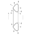
- FIG. 8 is a sectional view of the fluorescent tube shown in FIG. It is a bottom view for demonstrating the fluorescent tube which concerns on Embodiment 3 of this invention.
- FIG. 12 is a cross-sectional view of the fluorescent tube shown in FIG. 11 taken along the line XIII-XIII.
- Embodiment 1 A fluorescent tube according to Embodiment 1 of the present invention will be described with reference to the drawings.
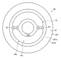
- the fluorescent tube 10 shown in FIGS. 1 to 4 is attached to an electrodeless illumination device 20.
- the electrodeless illumination device 20 is a pendant light that is suspended by a power cord (not shown).
- the electrodeless lighting device 20 includes a device main body 21, a shade 22, and an induction coil 23.
- the fluorescent tube 10 shown in FIGS. 3 and 4 has a fluorescent body attached to the inner surface of the tube main body 100.
- the tube body 100 is made of a resin having a thickness of about 2 mm.
- the pipe body 100 is made of polycarbonate or polyethylene.
- the width of the bottom surface (first irradiation surface described later) of the tube body 100 is formed to be about 5 cm.
- the contour shape of the tube body 100 is formed in a ring shape.
- the circular cross-sectional shape of the tube main body 100 is such that the first irradiation surface 101 that is the opposite irradiation surface facing the irradiated object positioned below, the second irradiation surface 102 and the third irradiation surface that the shade 22 (see FIG. 1) covers. 103 and a triangular shape.
- the first irradiation surface 101 is not a flat surface, but is a curved surface having an arc shape in the circular cross-sectional shape of the tube main body 100, but the virtual inscribed circle C is The curvature is smaller than that of the arc.
- the second irradiation surface 102 and the third irradiation surface 103 are also formed so as to have a smaller curvature than the arc of the virtual inscribed circle C, similarly to the first irradiation surface 101.
- An arcuate irradiation surface 104 is provided at both ends of the first irradiation surface 101. That is, the arcuate irradiation surface 104 is formed at the apex portion between the first irradiation surface 101 and the second irradiation surface 102 and at the apex portion between the first irradiation surface 101 and the second irradiation surface 102. Yes. In the first embodiment, the arcuate irradiation surface 104 is also formed at the apex portion between the second irradiation surface 102 and the third irradiation surface 103. The boundary between the first irradiation surface 101 to the third irradiation surface 103 and the arcuate irradiation surface 104 is a position where the curvature changes.
- the mounting portion 105 of the tube main body 100 wound around the induction coil 23 has a circular cross-sectional shape formed in a circular shape. Further, the mounting portion 105 is formed to be reduced from other portions.
- an ultraviolet protective layer 106 is formed on the inner surface and the outer surface of the tube body 100. This ultraviolet protective layer 106 shields ultraviolet rays or attenuates transmission of ultraviolet rays.
- a fluorescent layer 107 made of phosphor is formed on the inner surface of the ultraviolet protective layer 106 inside the tube main body 100.
- a housing chamber for housing a ballast constituted by a power supply circuit, an amplifier circuit, an oscillation circuit, and the like is formed inside the apparatus main body 21.
- the shade 22 includes an umbrella part 221 formed so as to cover the fluorescent tube 10 and a protrusion 222 protruding from the central part of the umbrella part 221 toward the central space of the tube main body 100.
- the inner surface of the umbrella 221 is a reflection surface that reflects light from the fluorescent tube 10.
- the umbrella part 221 includes a first inclined surface 221 a located at the upper part of the umbrella part 221 and a second inclined surface 221 b located at the lower part of the umbrella part 221.
- the first inclined surface 221 a is formed at an inclination angle so as to substantially face the second irradiation surface 102 of the fluorescent tube 10.
- the second inclined surface 221b is formed such that the inclination angle with respect to the horizontal direction is steeper than that of the first inclined surface 221a.
- the protrusion 222 is formed in a conical shape.
- the outer peripheral surface of the protrusion 222 is formed at an inclination angle so as to substantially face the third irradiation surface 103 of the fluorescent tube 10.
- the induction coil 23 is fixed to the tip of a support leg (not shown) attached to the shade 22 and wound around two places, one side of the fluorescent tube 10 and the other side opposite to the one side. 10 is held.
- the wiring to the induction coil 23 passes through the inside of the support leg, penetrates the bottom of the shade 22, and is connected to the ballast.
- the usage state of the fluorescent tube 10 according to Embodiment 1 of the present invention configured as described above will be described with reference to the drawings.
- the voltage is boosted by the power supply unit, converted into direct current, amplified by the amplification unit, oscillated by the oscillation unit, and then introduced into the induction coil 23. Supplied.
- a magnetic field along the circumferential direction of the fluorescent tube 10 is generated by the induction coil 23, ultraviolet rays are generated by exciting the discharge gas in the fluorescent tube 10.
- the fluorescent tube 10 is turned on when the phosphor of the fluorescent layer 107 (see FIG. 6) formed on the inner surface of the fluorescent tube 10 is excited by the generated ultraviolet light.
- the first irradiation surface 101 of the tube main body 100 is an opposite irradiation surface facing the irradiated body as an irradiation surface from which the fluorescent material emits light, and thus the irradiated body is irradiated with light almost straight. Can be made. Therefore, since the irradiated body can be illuminated brightly with respect to the periphery of the irradiated body, the illuminance to the irradiated body can be improved.
- the tube body 100 is made of resin, it is possible to easily form an irradiation surface close to a flat surface by the first irradiation surface 101 to the third irradiation surface 103, which is difficult to be formed with glass. A certain intensity can be secured from the first irradiation surface 101 to the third irradiation surface 103.
- the tube body 100 of the fluorescent tube 10 is made of resin, so that the internal pressure can be made higher than that of the glass fluorescent tube. Therefore, since the gas enclosed in the fluorescent tube of the present invention can be only a rare gas, the fluorescent tube 10 can be made mercury-free.
- the first irradiation surface 101 which is the opposite irradiation surface is formed in an arc shape having a smaller curvature than the arc of the virtual inscribed circle C in the circular cross-sectional shape of the tube body 100. From the circular fluorescent tube, it is possible to ensure a wider counter-irradiation surface facing the irradiated object. Also, the second irradiation surface 102 and the third irradiation surface 103 are formed so as to have a smaller curvature than the arc of the virtual inscribed circle C, similarly to the first irradiation surface 101. , The strength can be improved.
- the tube main body 100 has a circular cross-sectional shape, and has a first irradiation surface 101 that becomes an opposite irradiation surface, and a second irradiation surface 102 and a third irradiation surface 103 that the shade 22 covers. It is formed into a shape. Therefore, the irradiated body can be brightly illuminated by the first irradiation surface 101, and the light from the second irradiation surface 102 and the third irradiation surface 103 is reflected by the umbrella portion 221 and the protrusion 222 of the shade 22 to be irradiated on the irradiation body. Can be directed.
- the umbrella portion 221 of the shade 22 includes the first inclined surface 221a facing the second irradiation surface 102, the light from the second irradiation surface 102 can be directed downward toward the irradiated object. it can.
- the umbrella part 221 is provided with the 2nd inclined surface 221b with a larger inclination
- the arc-shaped irradiation surface 104 is provided between the first irradiation surface 101 and the second irradiation surface 102 of the tube main body 100, the light from the first irradiation surface 101 is transmitted from the front of the irradiated object. Irradiation can be performed, and light from the arc-shaped irradiation surface 104 can be irradiated around the irradiated object. Therefore, it can suppress that the circumference
- an arc shape is formed by making the apex portion between the first irradiation surface 101 and the second irradiation surface 102 and the apex portion between the first irradiation surface 101 and the third irradiation surface 103 angulated.
- the irradiated surface 104 is less likely to be dark.
- the shade 22 includes the protrusion 222 protruding toward the central space of the tube body 100, the light from the third irradiation surface 103 can be reflected by the tapered surface of the protrusion 222. It can be directed downward where the irradiated object is located.
- the tube body 100 is formed in a triangular shape by the first irradiation surface 101 to the third irradiation surface 103, but the mounting portion 105 of the tube body 100 wound around the induction coil 23 is formed in a circular shape. Therefore, when applying a magnetic field from the induction coil 23 to the inside of the mounting portion 105, it can be applied uniformly.
- the mounting portion 105 is formed to be reduced from other portions.
- the magnetic field when applied from the induction coil to the fluorescent tube, it can be applied evenly if the cross-sectional shape of the ring is circular, so that the mounting portion has a triangular shape formed by the first irradiation surface 101 to the third irradiation surface 103. It is good also as a circular shape circumscribing.
- the mounting portion has a circular shape circumscribing in a triangular shape by the first irradiation surface 101 to the third irradiation surface 103, the diameter increases, and the magnetic field reaches the center of the fluorescent tube unless the output of the induction coil is increased. May not reach.
- the mounting portion 105 according to the first embodiment is formed by contracting from other portions formed in a triangular shape by the first irradiation surface 101 to the third irradiation surface 103, so that a magnetic field is supplied from the induction coil 23 to the tube. It is easy to reach the center of the main body 100.
- the ultraviolet protective layer 106 is formed on the inner side surface and the outer side surface of the tube main body 100, the resin tube main body 100 can be protected from the ultraviolet rays generated in the tube main body 100 and is included in sunlight.
- the tube body can be protected from ultraviolet rays. Therefore, the fluorescent tube 10 can be installed not only indoors but also outdoors while being mounted on the electrodeless lighting device 20.
- the tube main body 100 is made of polycarbonate or polyethylene, sufficient strength can be ensured in the plane portion of the tube main body 100 by the first irradiation surface 101 to the third irradiation surface 103, and the tube main body 100 has an object. Even if a crack occurs due to a collision, it is difficult to crush and the fractured portion is difficult to sharpen.
- Embodiment 2 A fluorescent tube according to Embodiment 2 of the present invention will be described with reference to the drawings. 7 to 10, the same components as those in FIGS. 1 to 4 are denoted by the same reference numerals and description thereof is omitted.
- the circular cross section of the tube main body 110 is formed in a triangular shape from which two vertex portions are removed.
- the tube main body 110 is made of polycarbonate or polyethylene, like the tube main body 100 according to the first embodiment, and an ultraviolet protective layer is formed on the inner and outer surfaces of the tube main body 110 as shown in FIG.
- a fluorescent layer made of a phosphor is formed on the inner side surface of the ultraviolet protective layer inside the tube main body 110.
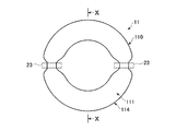
- the tube main body 110 is formed with a first irradiation surface 111 that is a counter-irradiation surface facing downward where the irradiated body is located, in a flat shape. Further, in the circular cross-sectional shape of the tube main body 110, the second irradiation surface 112 and the third irradiation surface 113 that are located at the upper portion of the tube main body 110 and connected at the upper end are formed in a flat shape. Further, the tube main body 110 is provided between the first irradiation surface 111 and the second irradiation surface 112 and between the first irradiation surface 111 and the third irradiation surface 113, which are both ends of the first irradiation surface 111. Since the planar irradiation surface 114 is provided in a state perpendicular to the one irradiation surface 111, the two vertexes of the triangular shape are removed.
- the 1st irradiation surface 111 is formed in planar shape, since a light can be irradiated straight to the to-be-irradiated body located below, brightness can be improved further. Further, since the planar irradiation surface 114 is formed on the tube main body 110, light is strongly emitted from the planar irradiation surface 114 to the side of the tube main body 110 toward the lower side where the irradiated object is located. Therefore, the light can be brightly irradiated by controlling the light with the first inclined surface 221a or the second inclined surface 221b of the shade 22. Since the planar irradiation surface 114 is formed in a planar shape, the reflection angle of the shade 22 can be easily designed.
- the second irradiation surface 112 and the third irradiation surface 113 are formed in a flat shape, it is easy to design the reflection angle of the shade 22 that reflects light from the second irradiation surface 112 and the third irradiation surface 113. It is.
- the fluorescent tube 12 according to the third embodiment is an electrodeless electrode having a width and length equivalent to a two-lamp type fluorescent lamp equipped with two straight tube fluorescent lamps. It is attached to the lighting device.
- the fluorescent tube 12 is made of polycarbonate or polyethylene, similar to the tube main body 100 according to the first embodiment, and an ultraviolet protective layer is formed on the inner and outer surfaces of the tube main body 110 as shown in FIG.
- a fluorescent layer made of a phosphor is formed on the inner side surface of the ultraviolet protective layer inside the tube main body 110.
- the tube body 120 of the fluorescent tube 12 is formed in a rectangular shape.
- An induction coil 23 is attached to the short side of the fluorescent tube 12.
- the circular cross-sectional shape of the tube main body 120 is the same as that of the tube main body 100 of the fluorescent tube 10 according to the first embodiment. That is, the tube main body 120 includes a first irradiation surface 101 that is an opposing irradiation surface facing an irradiation object positioned below, and a second irradiation surface 102 and a third irradiation surface 103 that are covered with a shade (not shown). It has a triangular shape.
- the fluorescent tube 12 is configured so that the first irradiation surface 101 of the tube main body 120 faces the irradiation target. Since it is a surface, it can irradiate light to a to-be-irradiated body substantially straight. Therefore, since the irradiated body can be illuminated brightly with respect to the periphery of the irradiated body, the illuminance to the irradiated body can be improved.
- the tube main body 120 is made of resin, the flat surfaces formed by the first irradiation surface 101 to the third irradiation surface 103, which are difficult to be formed with glass, can be easily formed, and the first irradiation serving as the opposite irradiation surface. A certain strength can be secured from the surface 101 to the third irradiation surface 103.
- the fluorescent tube of the present invention has a long life and can irradiate the irradiated object brightly, a conventional fluorescent tube having a filament, an LED tube, and a fluorescent tube of an electrodeless lighting device having a circular section in a circular shape. It is suitable as an alternative to
Landscapes
- Physics & Mathematics (AREA)
- Engineering & Computer Science (AREA)
- Plasma & Fusion (AREA)
- Electromagnetism (AREA)
- Discharge Lamps And Accessories Thereof (AREA)
- Vessels And Coating Films For Discharge Lamps (AREA)
- Non-Portable Lighting Devices Or Systems Thereof (AREA)
Abstract
被照射体を明るく照らすことができる蛍光管を提供する。無電極照明装置(20)には、無端状の管本体(100)を有する蛍光管(10)が装着される。この蛍光管(10)の管本体(100)は、ポリカーボネート製またはポリエチレン製である。管本体(100)の照射面は、被照射体に向いた対向照射面として第1照射面(101)と、セード(22)が被さる第2照射面(102)および第3照射面(103)とにより、輪切り断面が三角形状に形成されている。管本体(100)の第1照射面(101)が、被照射体に向いた対向照射面であるため、被照射体に対して、光をほぼ真っ直ぐ照射させることができる。従って、被照射体を、被照射体の周囲に対して明るく照らすことができるため、被照射体への照度を向上させることができる。
Description
本発明は、管本体の内側面に蛍光体が塗布され、無電極照明装置に装着される無端状の蛍光管に関するものである。
無電極照明装置は、密閉されたガラス管内に蛍光体が塗布された蛍光管を誘導コイルが巻回されている。無電極照明装置では、この誘導コイルに数十kHzから数百MHzの電流が流れる。すると、蛍光管内にプラズマ電流が発生し、このプラズマ電流による紫外線が、蛍光体を励起させることで、蛍光体が可視光を発光させる。無電極照明装置は、このようにして発光するため、蛍光管にフィラメントが不要であるので長寿であり、フィラメント付きの蛍光管を備えた従来の照明装置の代替となるものである。
このような無電極照明装置として特許文献1に記載のされたものが知られている。
従来の無電極照明装置は、リング状の蛍光管と、蛍光管の周囲を囲う略椀状のセードと、蛍光管に巻回され、蛍光管を電磁誘導により発光させる誘導コイルと、誘導コイルに電流を供給する安定器と、安定器を収容し、セードの底部に接続された装置本体とを備えている。セードの開口部には、平らな網目状の導電性部材により形成されたカバーが配置されている。カバーは、セードの開口部に形成された環状の段差部に嵌め込まれている。
従来の無電極照明装置は、リング状の蛍光管と、蛍光管の周囲を囲う略椀状のセードと、蛍光管に巻回され、蛍光管を電磁誘導により発光させる誘導コイルと、誘導コイルに電流を供給する安定器と、安定器を収容し、セードの底部に接続された装置本体とを備えている。セードの開口部には、平らな網目状の導電性部材により形成されたカバーが配置されている。カバーは、セードの開口部に形成された環状の段差部に嵌め込まれている。
従来の無電極照明装置では、輪切りの断面形状が真円の蛍光管が装着されている。そのため、蛍光管の照射面から出射した光は、蛍光管の表面から半径方向全体に拡がる。従って、照射光が被照射体だけでなく、被照射体の周囲にも拡がってしまうため、被照射体を明るく照らすことができない。
そこで本発明は、被照射体を明るく照らすことができる蛍光管を提供することを目的とする。
本発明は、無電極照明装置に装着される無端状の管本体を有する蛍光管において、前記管本体の照射面は、樹脂により形成され、被照射体に向いた対向照射面を備えたことを特徴とする。
管本体の照射面が、被照射体に向いた対向照射面を含むことにより、被照射体に対して、光をほぼ真っ直ぐ照射させることができる。従って、被照射体を、被照射体の周囲に対して明るく照らすことができるため、被照射体への照度を向上させることができる。また、本発明の蛍光管は、管本体が樹脂製であるため、ガラスでは成形が困難な照射面による平面も、容易に成形することができ、対向照射面に一定の強度を確保することができる。
前記対向照射面が、前記管本体の輪切り断面形状にて、仮想内接円の円弧より曲率の小さくなるように形成されているため、円形の蛍光管より、被照射体に向く対向照射面を広く確保することができる。
前記管本体を、輪切りの断面形状にて、前記対向照射面となる第1照射面と、前記無電極照明装置のセードが被さる第2照射面および第3照射面とを有する三角形状に形成することができる。従って、第1照射面により被照射体を明るく照らすことができ、第2および第3照射面からの光をセードに反射させ被照射体に向かわせることができる。
前記管本体は、輪切りの断面形状にて、前記対向照射面の一方の端部または両端部に、円弧状照射面が設けられているため、対向照射面からの光を、被照射体の正面から照射させることができると共に、円弧状照射面からの光を被照射体の周囲に照射させることができる。従って、被照射体の周囲が、被照射体に比べて極端に暗くなることを抑止することができる。また、管本体の角部が暗くなり難い。
前記管本体は、輪切りの断面形状にて、前記対向照射面の一方の端部または両端部に、平面状照射面が、前記対向照射面から垂直に設けられていることが望ましい。管本体に平面状照射面が形成されていることで、被照射体が位置する方向に対して直交する方向に光が平面状照射面から強く出射する。従って、セードなどの反射板により平面状照射面からの光を制御するときの反射角度の設計が容易である。
前記無電極照明装置の誘導コイルに巻かれた前記管本体の装着部の輪切りの断面形状が円形状に形成されているため、誘導コイルから装着部の内部に磁界を印加するときに、均等に印加することができる。
前記装着部が他の部分から縮小して形成されているため、誘導コイルから磁界を管本体の中心まで到達させやすい。
前記管本体の内側面と外側面とに、紫外線保護層が形成されているため、管本体内で発生する紫外線から樹脂製の管本体を保護することができ、太陽光に含まれる紫外線から管本体を保護することができる。
前記管本体が、ポリカーボネート製またはポリエチレン製であると、管本体の平面部分に十分な強度を確保することができると共に、管本体に物が衝突して亀裂が生じても、破砕し難く、破断部分が先鋭になり難い。
本発明は、樹脂により形成された管本体に、被照射体に向いた対向照射面が形成されているため、管本体の強度を確保しつつ、被照射体を明るく照らすことができる。
10,11,12 蛍光管
100,120 管本体
101 第1照射面
102 第2照射面
103 第3照射面
104 円弧状照射面
105 装着部
106 紫外線保護層
107 蛍光層
110 管本体
111 第1照射面
112 第2照射面
113 第3照射面
114 平面状照射面
20 無電極照明装置
21 装置本体
22 セード
221 傘部
221a 第1傾斜面
221b 第2傾斜面
222 突起部
23 誘導コイル
C 仮想内接円
100,120 管本体
101 第1照射面
102 第2照射面
103 第3照射面
104 円弧状照射面
105 装着部
106 紫外線保護層
107 蛍光層
110 管本体
111 第1照射面
112 第2照射面
113 第3照射面
114 平面状照射面
20 無電極照明装置
21 装置本体
22 セード
221 傘部
221a 第1傾斜面
221b 第2傾斜面
222 突起部
23 誘導コイル
C 仮想内接円
(実施の形態1)
本発明の実施の形態1に係る蛍光管を図面に基づいて説明する。
図1から図4に示す蛍光管10は、無電極照明装置20に装着されている。無電極照明装置20は、図示しない電源コードにより吊り下げられるペンダントライトである。無電極照明装置20は、装置本体21と、セード22と、誘導コイル23とを備えている。
本発明の実施の形態1に係る蛍光管を図面に基づいて説明する。
図1から図4に示す蛍光管10は、無電極照明装置20に装着されている。無電極照明装置20は、図示しない電源コードにより吊り下げられるペンダントライトである。無電極照明装置20は、装置本体21と、セード22と、誘導コイル23とを備えている。
図3および図4に示す蛍光管10は、管本体100の内側面に蛍光体を付着させたものである。管本体100は、肉厚が約2mmの樹脂により形成されている。本実施の形態1では、管本体100は、ポリカーボネート製またはポリエチレン製である。管本体100の底面(後述する第1照射面)の幅は、約5cmに形成されている。
管本体100の輪郭形状は、リング状に形成されている。管本体100の輪切り断面形状は、下方に位置する被照射体に向いた対向照射面となる第1照射面101と、セード22(図1参照)が被さる第2照射面102および第3照射面103とを有する三角形状に形成されている。
図5に示すように、第1照射面101は、本実施の形態1では、平面で無く、管本体100の輪切り断面形状にて、円弧状となる曲面であるが、仮想内接円Cの円弧より曲率が小さくなるように形成されている。また、第2照射面102および第3照射面103についても、第1照射面101と同様に、仮想内接円Cの円弧より曲率の小さくなるように形成されている。
第1照射面101の両端部には、円弧状照射面104が設けられている。すなわち、円弧状照射面104は、第1照射面101と第2照射面102との間の頂点部分と、第1照射面101と第2照射面102との間の頂点部分とに形成されている。本実施の形態1では、第2照射面102と第3照射面103との間の頂点部分にも、円弧状照射面104が形成されている。第1照射面101~第3照射面103と、円弧状照射面104との境界は、曲率が変化する位置である。
図3および図4に示すように、誘導コイル23に巻かれた管本体100の装着部105は、輪切りの断面形状が円形状に形成されている。また、この装着部105は、他の部分から縮小して形成されている。
図6に示すように、管本体100の内側面と外側面とに、紫外線保護層106が形成されている。この紫外線保護層106は、紫外線を遮蔽または紫外線の透過を減衰させるものである。管本体100内側の紫外線保護層106の内側面に、蛍光体による蛍光層107が形成されている。
図6に示すように、管本体100の内側面と外側面とに、紫外線保護層106が形成されている。この紫外線保護層106は、紫外線を遮蔽または紫外線の透過を減衰させるものである。管本体100内側の紫外線保護層106の内側面に、蛍光体による蛍光層107が形成されている。
図1および図2に示すように、装置本体21の内部には、電源回路、増幅回路、発振回路などにより構成された安定器を収容する収容室が形成されている。
セード22は、蛍光管10の周囲に被るように形成された傘部221と、傘部221の中央部から管本体100の中央空間に向かって突出した突起部222とを備えている。
セード22は、蛍光管10の周囲に被るように形成された傘部221と、傘部221の中央部から管本体100の中央空間に向かって突出した突起部222とを備えている。
傘部221は、内側面が蛍光管10からの光を反射する反射面となる。傘部221は、傘部221の上部に位置する第1傾斜面221aと、傘部221の下部に位置する第2傾斜面221bとを備えている。第1傾斜面221aは、蛍光管10の第2照射面102とほぼ対向するような傾斜角度に形成されている。第2傾斜面221bは、第1傾斜面221aより水平方向に対する傾斜角度が急になるように形成されている。
突起部222は、円錐形状に形成されている。突起部222の外周面は、蛍光管10の第3照射面103とほぼ対向するような傾斜角度に形成されている。
突起部222は、円錐形状に形成されている。突起部222の外周面は、蛍光管10の第3照射面103とほぼ対向するような傾斜角度に形成されている。
誘導コイル23は、セード22に取り付けられた、図示しない支持脚の先端に固定され、蛍光管10の一側と、この一側と反対となる他側の2ヵ所に巻回されて、蛍光管10を保持している。誘導コイル23への配線は、支持脚の内部を通って、セード22の底部を貫通し、安定器へ接続されている。
以上のように構成された本発明の実施の形態1に係る蛍光管10の使用状態について、図面に基づいて説明する。
図1から図4に示すように、安定器に電源が供給されると、電源部にて昇圧されて直流に変換され、増幅部にて増幅され、発振部にて発振されて誘導コイル23に供給される。
誘導コイル23にて蛍光管10の円周方向に沿った磁界が発生すると、蛍光管10内の放電ガスが励起されることで紫外線が発生する。発生した紫外線により蛍光管10の内側面に形成した蛍光層107(図6参照)の蛍光体が励起されることで、蛍光管10が点灯する。
図1から図4に示すように、安定器に電源が供給されると、電源部にて昇圧されて直流に変換され、増幅部にて増幅され、発振部にて発振されて誘導コイル23に供給される。
誘導コイル23にて蛍光管10の円周方向に沿った磁界が発生すると、蛍光管10内の放電ガスが励起されることで紫外線が発生する。発生した紫外線により蛍光管10の内側面に形成した蛍光層107(図6参照)の蛍光体が励起されることで、蛍光管10が点灯する。
蛍光管10は、蛍光体が発光する照射面として、管本体100の第1照射面101が、被照射体に向いた対向照射面であるため、被照射体に対して、光をほぼ真っ直ぐ照射させることができる。従って、被照射体を、被照射体の周囲に対して明るく照らすことができるため、被照射体への照度を向上させることができる。また、管本体100は、樹脂製であるため、ガラスでは成形が困難な第1照射面101~第3照射面103による平面に近い照射面も、容易に成形することができ、対向照射面となる第1照射面101から第3照射面103に一定の強度を確保することができる。
更に、蛍光管10の管本体100を樹脂製とすることで、ガラス製の蛍光管より、内部の圧力を高めた状態とすることができる。従って、本発明の蛍光管に封入するガスを希ガスのみとすることができるため、蛍光管10は水銀レスとすることができる。
図5に示すように、対向照射面となる第1照射面101が、管本体100の輪切り断面形状にて、仮想内接円Cの円弧より曲率の小さく円弧状に形成されているため、真円の蛍光管より、被照射体に向く対向照射面を広く確保することができる。また、第2照射面102および第3照射面103についても、第1照射面101と同様に、仮想内接円Cの円弧より曲率の小さくなるように形成されているため、単なる平面とするより、強度を向上させることができる。
図1に示すように、管本体100が、輪切りの断面形状にて、対向照射面となる第1照射面101と、セード22が被さる第2照射面102および第3照射面103とを有する三角形状に形成されている。従って、第1照射面101により被照射体を明るく照らすことができ、第2照射面102および第3照射面103からの光をセード22の傘部221および突起部222に反射させ被照射体に向かわせることができる。
更に、セード22の傘部221が、第2照射面102と対向する第1傾斜面221aを備えているため、第2照射面102からの光を下方に向けて被照射体へ向かわせることができる。また、傘部221が、第1傾斜面221aより水平方向に対する傾斜角度が大きい第2傾斜面221bを備えているため、第1照射面101と第2照射面102との間の頂点部分とに形成された円弧状照射面104から周囲に拡がる光を、下方に向けて被照射体へ向かわせることができる。
また、管本体100の第1照射面101と第2照射面102との間に、円弧状照射面104が設けられているため、第1照射面101からの光を、被照射体の正面から照射させることができると共に、円弧状照射面104からの光を被照射体の周囲に照射させることができる。従って、被照射体の周囲が、被照射体に比べて極端に暗くなることを抑止することができる。更に、円弧状照射面104が円弧状に形成されているため、平面とするより強度を向上させることができる。
また、第1照射面101と第2照射面102との間の頂点部分、および第1照射面101と第3照射面103との間の頂点部分を角張らせるより、円弧状とした円弧状照射面104の方が暗くなり難い。
また、第1照射面101と第2照射面102との間の頂点部分、および第1照射面101と第3照射面103との間の頂点部分を角張らせるより、円弧状とした円弧状照射面104の方が暗くなり難い。
また、セード22は、管本体100の中央空間に向かって突出した突起部222を備えているため、第3照射面103からの光を、突起部222のテーパ面により反射することができるので、被照射体が位置する下方へ向けることができる。
管本体100は、第1照射面101~第3照射面103による三角形状に形成されているが、誘導コイル23に巻かれた管本体100の装着部105は円形状に形成されている。そのため、誘導コイル23から装着部105の内部に磁界を印加するときに、均等に印加することができる。
図4に示すように、この装着部105は、他の部分から縮小して形成されている。
例えば、誘導コイルから蛍光管に磁界を印加するときに、輪切り断面形状が円形状であれば均等に印加することができるため、装着部を第1照射面101~第3照射面103による三角形状に外接する円形状としてもよい。しかし、装着部を第1照射面101~第3照射面103による三角形状に外接する円形状とすると、直径が大きくなってしまい、誘導コイルの出力を上げなければ、磁界が蛍光管の中心まで届かないおそれがある。
本実施の形態1に係る装着部105は、第1照射面101~第3照射面103による三角形状に形成された他の部分から縮小して形成されているため、誘導コイル23から磁界を管本体100の中心まで到達させやすい。
例えば、誘導コイルから蛍光管に磁界を印加するときに、輪切り断面形状が円形状であれば均等に印加することができるため、装着部を第1照射面101~第3照射面103による三角形状に外接する円形状としてもよい。しかし、装着部を第1照射面101~第3照射面103による三角形状に外接する円形状とすると、直径が大きくなってしまい、誘導コイルの出力を上げなければ、磁界が蛍光管の中心まで届かないおそれがある。
本実施の形態1に係る装着部105は、第1照射面101~第3照射面103による三角形状に形成された他の部分から縮小して形成されているため、誘導コイル23から磁界を管本体100の中心まで到達させやすい。
管本体100の内側面と外側面とに、紫外線保護層106が形成されているため、管本体100内で発生する紫外線から樹脂製の管本体100を保護することができ、太陽光に含まれる紫外線から管本体を保護することができる。従って、蛍光管10は、無電極照明装置20に装着された状態で、屋内だけでなく、屋外への設置も可能である。
管本体100が、ポリカーボネート製またはポリエチレン製であるため、管本体100の第1照射面101~第3照射面103による平面部分に十分な強度を確保することができると共に、管本体100に物が衝突して亀裂が生じても、破砕し難く、破断部分が先鋭になり難い。
(実施の形態2)
本発明の実施の形態2に係る蛍光管を図面に基づいて説明する。なお、図7から図10においては、図1から図4と同じ構成のものは同符号を付して説明を省略する。
図7から図10に示すように、本実施の形態2に係る蛍光管11は、管本体110の輪切り断面形状が2つの頂点部分が除かれた三角形状に形成されている。管本体110は、実施の形態1に係る管本体100と同様に、ポリカーボネート製またはポリエチレン製であり、図6に示すように、管本体110の内側面と外側面とに、紫外線保護層が形成され、管本体110内側の紫外線保護層の内側面に、蛍光体による蛍光層が形成されている。
本発明の実施の形態2に係る蛍光管を図面に基づいて説明する。なお、図7から図10においては、図1から図4と同じ構成のものは同符号を付して説明を省略する。
図7から図10に示すように、本実施の形態2に係る蛍光管11は、管本体110の輪切り断面形状が2つの頂点部分が除かれた三角形状に形成されている。管本体110は、実施の形態1に係る管本体100と同様に、ポリカーボネート製またはポリエチレン製であり、図6に示すように、管本体110の内側面と外側面とに、紫外線保護層が形成され、管本体110内側の紫外線保護層の内側面に、蛍光体による蛍光層が形成されている。
管本体110は、被照射体が位置する下方に向いた対向照射面である第1照射面111が平面状に形成されている。また、管本体110の輪切り断面形状において、管本体110の上部に位置し、上端で接続された第2照射面112および第3照射面113は、平面状に形成されている。
また、管本体110は、第1照射面111の両端部となる、第1照射面111と第2照射面112との間、第1照射面111と第3照射面113との間に、第1照射面111から垂直の状態で平面状照射面114が設けられていることで、三角形状の2つの頂点部分が除かれた形状に形成されている。
また、管本体110は、第1照射面111の両端部となる、第1照射面111と第2照射面112との間、第1照射面111と第3照射面113との間に、第1照射面111から垂直の状態で平面状照射面114が設けられていることで、三角形状の2つの頂点部分が除かれた形状に形成されている。
このように第1照射面111が平面状に形成されているため、下方に位置する被照射体にまっすぐ光を照射することができるので、更に、明るさを向上させることができる。
また、管本体110に平面状照射面114が形成されていることで、被照射体が位置する下方に対して、光が平面状照射面114から管本体110の側方へ強く出射する。
従って、セード22の第1傾斜面221aまたは第2傾斜面221bでこの光を制御して明るく照射することができる。平面状照射面114が平面状に形成されているため、セード22の反射角度の設計が容易である。
また、管本体110に平面状照射面114が形成されていることで、被照射体が位置する下方に対して、光が平面状照射面114から管本体110の側方へ強く出射する。
従って、セード22の第1傾斜面221aまたは第2傾斜面221bでこの光を制御して明るく照射することができる。平面状照射面114が平面状に形成されているため、セード22の反射角度の設計が容易である。
更に、第2照射面112および第3照射面113が平面状に形成されているため、第2照射面112と第3照射面113とからの光を反射させるセード22の反射角度の設計が容易である。
(実施の形態3)
本発明の実施の形態3に係る蛍光管を図面に基づいて説明する。なお、図11から図13においては、図3および図4と同じ構成のものは同符号を付して説明を省略する。
図11から図13に示すように、本実施の形態3に係る蛍光管12は、直管形の蛍光灯が2本装着される二灯式蛍光灯具と同等の幅や長さを有する無電極照明装置に装着されるものである。
本発明の実施の形態3に係る蛍光管を図面に基づいて説明する。なお、図11から図13においては、図3および図4と同じ構成のものは同符号を付して説明を省略する。
図11から図13に示すように、本実施の形態3に係る蛍光管12は、直管形の蛍光灯が2本装着される二灯式蛍光灯具と同等の幅や長さを有する無電極照明装置に装着されるものである。
蛍光管12は、実施の形態1に係る管本体100と同様に、ポリカーボネート製またはポリエチレン製であり、図6に示すように、管本体110の内側面と外側面とに、紫外線保護層が形成され、管本体110内側の紫外線保護層の内側面に、蛍光体による蛍光層が形成されている。
蛍光管12の管本体120が矩形状に形成されている。蛍光管12の短辺に誘導コイル23が装着される。
管本体120の輪切り断面形状は、実施の形態1に係る蛍光管10の管本体100と同じである。つまり、管本体120は、下方に位置する被照射体に向いた対向照射面となる第1照射面101と、セード(図示せず)が被さる第2照射面102および第3照射面103とを有する三角形状に形成されている。
管本体120の輪切り断面形状は、実施の形態1に係る蛍光管10の管本体100と同じである。つまり、管本体120は、下方に位置する被照射体に向いた対向照射面となる第1照射面101と、セード(図示せず)が被さる第2照射面102および第3照射面103とを有する三角形状に形成されている。
このように、対向した二辺が長尺な矩形状に形成された蛍光管12であっても、蛍光管12は、管本体120の第1照射面101が、被照射体に向いた対向照射面であるため、被照射体に対して、光をほぼ真っ直ぐ照射させることができる。従って、被照射体を、被照射体の周囲に対して明るく照らすことができるため、被照射体への照度を向上させることができる。また、管本体120は、樹脂製であるため、ガラスでは成形が困難な第1照射面101~第3照射面103による平面も、容易に成形することができ、対向照射面となる第1照射面101から第3照射面103に一定の強度を確保することができる。
本発明の蛍光管は、長寿命であり、被照射体を明るく照射することができるので、フィラメントを有する従来の蛍光管や、LED管、更に輪切り断面が円筒形状の無電極照明装置の蛍光管の代替品として好適である。
Claims (9)
- 無電極照明装置に装着される無端状の管本体を有する蛍光管において、
前記管本体は、樹脂により形成され、
前記管本体の照射面は、被照射体に向いた対向照射面を備えた蛍光管。 - 前記対向照射面は、前記管本体の輪切り断面形状にて、仮想内接円の円弧より曲率が小さくなるように形成された請求項1記載の蛍光管。
- 前記管本体は、輪切りの断面形状にて、前記対向照射面となる第1照射面と、前記無電極照明装置のセードが被さる第2照射面および第3照射面とを有する三角形状に形成された請求項1または2記載の蛍光管。
- 前記管本体は、輪切りの断面形状にて、前記対向照射面の一方の端部または両端部に、円弧状照射面が設けられた請求項1または2記載の蛍光管。
- 前記管本体は、輪切りの断面形状にて、前記対向照射面の一方の端部または両端部に、平面状照射面が、前記対向照射面から垂直に設けられた請求項1または2記載の蛍光管。
- 前記無電極照明装置の誘導コイルに巻かれた前記管本体の装着部は、輪切りの断面形状が円形状に形成された請求項1記載の蛍光管。
- 前記装着部は、他の部分から縮小して形成された請求項6記載の蛍光管。
- 前記管本体の内側面と外側面とに、紫外線保護層が形成された請求項1記載の蛍光管。
- 前記管本体は、ポリカーボネート製またはポリエチレン製である請求項1記載の蛍光管。
Applications Claiming Priority (2)
| Application Number | Priority Date | Filing Date | Title |
|---|---|---|---|
| JP2015146630A JP2017027835A (ja) | 2015-07-24 | 2015-07-24 | 蛍光管 |
| JP2015-146630 | 2015-07-24 |
Publications (1)
| Publication Number | Publication Date |
|---|---|
| WO2017018308A1 true WO2017018308A1 (ja) | 2017-02-02 |
Family
ID=57884694
Family Applications (1)
| Application Number | Title | Priority Date | Filing Date |
|---|---|---|---|
| PCT/JP2016/071360 Ceased WO2017018308A1 (ja) | 2015-07-24 | 2016-07-21 | 蛍光管 |
Country Status (2)
| Country | Link |
|---|---|
| JP (1) | JP2017027835A (ja) |
| WO (1) | WO2017018308A1 (ja) |
Citations (9)
| Publication number | Priority date | Publication date | Assignee | Title |
|---|---|---|---|---|
| JPS52117373U (ja) * | 1976-02-07 | 1977-09-06 | ||
| JPS52161972U (ja) * | 1976-06-01 | 1977-12-08 | ||
| JPS55171962U (ja) * | 1979-05-29 | 1980-12-10 | ||
| JPS59143253A (ja) * | 1983-02-04 | 1984-08-16 | Shigeo Yoshino | 螢光ランプ |
| JPS62167361U (ja) * | 1986-04-14 | 1987-10-23 | ||
| JP2003007252A (ja) * | 2001-06-19 | 2003-01-10 | Harison Toshiba Lighting Corp | 冷陰極蛍光ランプ及び照明装置 |
| JP2006523922A (ja) * | 2003-04-16 | 2006-10-19 | コーニンクレッカ フィリップス エレクトロニクス エヌ ヴィ | 高圧メタルハライド放電ランプ |
| JP2007115531A (ja) * | 2005-10-20 | 2007-05-10 | Tsutomu Inaba | 蛍光ランプ |
| JP2009129806A (ja) * | 2007-11-27 | 2009-06-11 | Panasonic Electric Works Co Ltd | 無電極放電灯装置及び照明器具 |
-
2015
- 2015-07-24 JP JP2015146630A patent/JP2017027835A/ja active Pending
-
2016
- 2016-07-21 WO PCT/JP2016/071360 patent/WO2017018308A1/ja not_active Ceased
Patent Citations (9)
| Publication number | Priority date | Publication date | Assignee | Title |
|---|---|---|---|---|
| JPS52117373U (ja) * | 1976-02-07 | 1977-09-06 | ||
| JPS52161972U (ja) * | 1976-06-01 | 1977-12-08 | ||
| JPS55171962U (ja) * | 1979-05-29 | 1980-12-10 | ||
| JPS59143253A (ja) * | 1983-02-04 | 1984-08-16 | Shigeo Yoshino | 螢光ランプ |
| JPS62167361U (ja) * | 1986-04-14 | 1987-10-23 | ||
| JP2003007252A (ja) * | 2001-06-19 | 2003-01-10 | Harison Toshiba Lighting Corp | 冷陰極蛍光ランプ及び照明装置 |
| JP2006523922A (ja) * | 2003-04-16 | 2006-10-19 | コーニンクレッカ フィリップス エレクトロニクス エヌ ヴィ | 高圧メタルハライド放電ランプ |
| JP2007115531A (ja) * | 2005-10-20 | 2007-05-10 | Tsutomu Inaba | 蛍光ランプ |
| JP2009129806A (ja) * | 2007-11-27 | 2009-06-11 | Panasonic Electric Works Co Ltd | 無電極放電灯装置及び照明器具 |
Non-Patent Citations (1)
| Title |
|---|
| KABUSHIKI KAISHA ASC: "LVD SOLUTION ECOLVD", November 2014 (2014-11-01), Retrieved from the Internet <URL:http://www.asc-led.co.jp/labout/ asc.pdf> [retrieved on 20161011] * |
Also Published As
| Publication number | Publication date |
|---|---|
| JP2017027835A (ja) | 2017-02-02 |
Similar Documents
| Publication | Publication Date | Title |
|---|---|---|
| CN101521140A (zh) | 灯泡形荧光灯以及照明器具 | |
| WO2017018308A1 (ja) | 蛍光管 | |
| JPWO2009019978A1 (ja) | 放電ランプ | |
| JP2011134640A (ja) | 照明器具 | |
| JP2011108605A (ja) | 照明器具 | |
| US20100110694A1 (en) | Compact beam former for induction hid lamp | |
| JP5213253B2 (ja) | 照明器具 | |
| KR101452733B1 (ko) | 무전극 램프 구조체 및 이에 장착되는 엔벨로프 | |
| JP2014127425A (ja) | 無電極照明装置 | |
| JP2010146946A (ja) | 反射鏡付き照明器具 | |
| JP3169032U (ja) | 照明器具 | |
| JP4577453B2 (ja) | 高輝度放電灯用照明器具 | |
| JP5180404B2 (ja) | 放電ランプおよび照明装置 | |
| JP4577454B2 (ja) | 高輝度放電灯用照明器具 | |
| KR100852731B1 (ko) | 소켓형 무전극 램프 | |
| JP2005063934A (ja) | 無電極電球 | |
| TWI447776B (zh) | 可自行反射的無極燈具 | |
| CN103843108B (zh) | 用于汽车前照灯的金属卤化物灯和具有所述灯的前照灯 | |
| KR20050113050A (ko) | 무전극 조명기기의 프론트 글래스 고정구조 | |
| KR101625062B1 (ko) | 무전극 조명장치 | |
| JPS5838840B2 (ja) | 交通信号器用照明装置 | |
| KR20010054599A (ko) | 무전극 램프의 집광장치 | |
| JP2013051067A (ja) | 照明器具 | |
| JP2011238411A (ja) | 照明器具 | |
| JP2007073461A (ja) | 高輝度放電ランプまたは反射鏡付高輝度放電ランプ |
Legal Events
| Date | Code | Title | Description |
|---|---|---|---|
| 121 | Ep: the epo has been informed by wipo that ep was designated in this application |
Ref document number: 16830413 Country of ref document: EP Kind code of ref document: A1 |
|
| NENP | Non-entry into the national phase |
Ref country code: DE |
|
| 122 | Ep: pct application non-entry in european phase |
Ref document number: 16830413 Country of ref document: EP Kind code of ref document: A1 |