WO2017018367A1 - Dispositif de génération d'énergie solaire - Google Patents
Dispositif de génération d'énergie solaire Download PDFInfo
- Publication number
- WO2017018367A1 WO2017018367A1 PCT/JP2016/071677 JP2016071677W WO2017018367A1 WO 2017018367 A1 WO2017018367 A1 WO 2017018367A1 JP 2016071677 W JP2016071677 W JP 2016071677W WO 2017018367 A1 WO2017018367 A1 WO 2017018367A1
- Authority
- WO
- WIPO (PCT)
- Prior art keywords
- power generation
- generation device
- solar power
- ribbon
- solar
- Prior art date
- Legal status (The legal status is an assumption and is not a legal conclusion. Google has not performed a legal analysis and makes no representation as to the accuracy of the status listed.)
- Ceased
Links
Images



Classifications
-
- H—ELECTRICITY
- H02—GENERATION; CONVERSION OR DISTRIBUTION OF ELECTRIC POWER
- H02S—GENERATION OF ELECTRIC POWER BY CONVERSION OF INFRARED RADIATION, VISIBLE LIGHT OR ULTRAVIOLET LIGHT, e.g. USING PHOTOVOLTAIC [PV] MODULES
- H02S20/00—Supporting structures for PV modules
- H02S20/30—Supporting structures being movable or adjustable, e.g. for angle adjustment
- H02S20/32—Supporting structures being movable or adjustable, e.g. for angle adjustment specially adapted for solar tracking
-
- Y—GENERAL TAGGING OF NEW TECHNOLOGICAL DEVELOPMENTS; GENERAL TAGGING OF CROSS-SECTIONAL TECHNOLOGIES SPANNING OVER SEVERAL SECTIONS OF THE IPC; TECHNICAL SUBJECTS COVERED BY FORMER USPC CROSS-REFERENCE ART COLLECTIONS [XRACs] AND DIGESTS
- Y02—TECHNOLOGIES OR APPLICATIONS FOR MITIGATION OR ADAPTATION AGAINST CLIMATE CHANGE
- Y02E—REDUCTION OF GREENHOUSE GAS [GHG] EMISSIONS, RELATED TO ENERGY GENERATION, TRANSMISSION OR DISTRIBUTION
- Y02E10/00—Energy generation through renewable energy sources
- Y02E10/50—Photovoltaic [PV] energy
Definitions
- a solar power generation apparatus that generates power using solar energy.
- a solar power generation device with a tracking device that performs tracking control for driving a solar cell panel so as to track a preset solar orbit.
- the tracking device generally includes a drive device that drives a solar cell panel, and a control unit that controls the drive of the drive device by calculating a drive amount of the drive device so as to match a preset solar orbit. .
- an object of the present invention is to provide a photovoltaic power generation apparatus that includes a tracking device that is a distributed movable type, has excellent convenience during installation and portability during transportation, and can be realized at low cost. It is.
- a plurality of solar panels arranged in an array and converting sunlight into electric power;
- a driving device for driving a plurality of solar cell panels;
- a control device for controlling the drive amount of the drive device so that a plurality of solar battery panels track a preset solar trajectory;
- a photovoltaic power generation device including a tracking device,
- the tracking device Provided with a plurality of trackers each mounting a plurality of solar cell panels, Each of the plurality of trackers A holding member for mounting the solar cell panel;
- a tracking mechanism connected to the holding member, Based on the controlled driving amount of the driving device, the solar panel tracks a preset solar trajectory by driving at least three points on the holding member. It is characterized by that.
- each of the trackers on which the solar cell panel is mounted can be driven by the drive device. Moreover, the solar cell panel can be accurately tracked to the solar orbit by the structure in which at least three points of the holding member are driven.
- a solar power generation apparatus including a solar tracking apparatus that is of a distributed movable type and has a simple structure and can be realized at low cost can be realized.
- the drive device includes at least three drive units that respectively drive at least three points of the holding member. It is preferable.
- the solar cell panel can be accurately tracked in the solar orbit with a simple structure.
- the first driving unit includes a first motor that winds the first ribbon
- the second drive unit comprises a second motor that winds the second ribbon
- the third driving unit includes a load applying member that applies a load to the remaining third driving point among the three points.
- the control device Controlling the amount of winding of each of the first motor and the second motor, and controlling the load applied by the load applying member; It is preferable.
- the remaining one of the three points may be driven, for example, when returning from the position where the other two points are driven, so that it is different from the control of the other two points. It can be realized with a structure that does not require precise position control.
- a wire, a wire with a spring interposed, or a constant load spring is attached as a load applying member. It may be.
- a third ribbon is attached to the third driving point instead of the load applying member. It may be.
- the third ribbon can also be wound up by rotation.
- a double-edged ribbon having a plurality of teeth on both sides is selectively used as the first ribbon, the second ribbon, and the third ribbon.
- the interval between the plurality of teeth on the outside when the double-edged ribbon is wound is equal to the interval between the plurality of teeth on the inner side of the linear state before the double-edged ribbon is wound. It is preferable.
- the tracking mechanism A column supporting the holding member; With a base part that supports the column part, A ring for connecting the holding member and the support column is further provided; It is preferable.
- the holding member and the support column are connected by the ring, the holding member is driven smoothly through the ring. As a result, the solar cell panel can be more accurately tracked in the solar orbit.
- the tracking mechanism A first guide and a second guide that respectively pass the first ribbon and the second ribbon are provided in the base portion. It is preferable.
- first and second ribbons can be accurately wound through the first and second guides, and the wire can be accurately wound through the opening of the protrusion.
- the support column is provided with a pair of shoulders that limit the drive amount of the support member. It is preferable.
- the tracking mechanism It further includes a wall part that holds the lower part of the column part so as to cover it,
- the base part is provided with a groove part that can store the column part,
- the strut is While using the tracker, while standing upright by the penetrating member that penetrates the support column from the wall portion, when the tracker is transported, it is accommodated in the groove portion by removing and tilting the penetrating member. It is preferable.
- At least a first electric line and a second electric line connected to a plurality of trackers and acquiring electricity from the solar cell panel; In consideration of the shaded area on the solar cell panel via a signal line continuously connected to each of the trackers arranged in one of two directions perpendicularly intersecting among the plurality of trackers.
- a shadow control unit for controlling electrical connection of the first electric line and the second electric line to the tracker It is preferable.
- a platform with a tracking device A rectangular case made of a transparent member provided to cover the entire tracking device on the gantry, and further includes At least one side of the case is inclined, It is preferable.
- a plurality of tracking devices connected to each other, One control device drives a plurality of tracking devices via the drive device. It is preferable.
- a plurality of tracking devices can be centrally controlled via a single control device, and a solar power generation device including a plurality of tracking devices with a simple structure can be realized.
- a photovoltaic power generation apparatus that is of a distributed movable type, has excellent convenience during installation and portability during transportation, and includes a tracking device that can be realized at low cost.
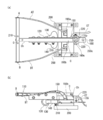
- FIG. 1 shows a structure of a tracking device constituting a tracking device according to an embodiment of the present invention, in a folded state, and (a) is a diagram viewed from substantially above the tracking device; ) Is a view of the tracker viewed from a substantially lateral direction. It is a figure which shows the example of a wiring and a transmission shaft structure for implement
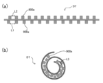
- (A) is a figure which shows the structural example of the ribbon used for the tracker concerning one Embodiment of this invention, Comprising: It is a figure of the linear state before winding up, (b) is based on one Embodiment of this invention. It is a figure which shows the structural example of the ribbon used for a tracker, Comprising: It is a figure of the state at the time of winding up.
- the tracking device 500 includes a plurality of trackers 100 each having a size of, for example, about 10 cm to 50 cm square, on which each of the solar cell panels 10 arranged in an array is mounted. It has.
- the tracking device 500 is disposed on the gantry 20 provided on the base 40 via the support column 30.
- the size of the tracking device 500 is, for example, about 1 m ⁇ 2 m.
- the gantry 20 shows an example in which each of the solar cell panels 10 mounted on the tracking device 100 is inclined upward toward the north side, but is not inclined or inclined in other directions. It may be.
- the number of the solar cell panels 10 arranged in an array, the size of the tracker 100, and the size of the tracking device 500 are shown here as examples, and are shown in FIG. It is not limited to things.
- the solar power generation device includes, for example, a tracking device 500 including a plurality of the tracking units 100 illustrated in FIG. 2 on which the solar cell panel 10 is mounted, and further drives the plurality of solar cell panels 10, for example, as illustrated in FIG.
- the driving device 450 includes a control device 400 shown in FIG. 4 for controlling the driving amount of the driving device 450 so that the plurality of solar battery panels 10 track a preset solar orbit.
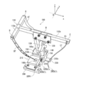
- FIG. 2 specifically shows the structure of the tracker 100 constituting the tracking device 500 in the present embodiment.
- the tracker 100 includes, for example, a T-shaped holding member 110 (consisting of a 110a portion and a 110b portion) on which the solar cell panel 10 is mounted, and a tracking mechanism connected to the holding member 110. It has.
- the tracking mechanism is installed and used on the gantry 20 shown in FIG. 1 with the solar cell panel 10 mounted on the holding member 110 to be connected.
- the tracker 100 drives the solar cell panel 10 in advance by driving at least three points in the holding member 110 based on the controlled driving amount of the driving device 450. It is configured to track the trajectory.
- a T-shaped member is used as an example of the shape of the holding member 110.
- three end portions first driving point to first driving point
- the first end A and the second end B as a pair of opposing ends of the first ribbon A and the second end B of FIG.
- the second ribbon BT is attached by, for example, a screw, and a wire CT is attached to the third end C as the remaining end via an opening Ch, for example.
- the driving device 450 shown in FIG. 4 includes, for example, a first motor 450a and a second motor 450c, which are, for example, servomotors for winding the first ribbon AT and the second ribbon BT, and the wires.
- a third motor 450b which is a stepping motor for winding is provided.
- the control device 400 controls the amount of winding of each of the first motor 450a, the second motor 450c, and the third motor 450b.
- a constant load spring for applying a constant load can be provided instead of the third motor 450b. In this case, the tip of the constant load spring is not provided with the wire CT. You may make it attach to the part C.
- the solar power generation device including the tracking device 500 can drive each of the trackers 100 on which the solar cell panel 10 is mounted by the driving device 450. That is, the solar cell panel can be accurately tracked in the solar orbit by the structure in which the positions of the three points on the holding member 110 are controlled and driven.
- a photovoltaic power generation apparatus including the tracking device 500 that is a distributed movable type has a simple structure, and can be realized at low cost can be realized.
- a plurality of solar battery panels 10 can be centrally controlled by a single control device 400 via a plurality of trackers 100, and a solar power generation device including a tracking device 500 having a simple structure is realized. can do.
- this embodiment demonstrated the case where the shape of the holding member 110 was T-shaped, this invention is not limited to this shape, Various shapes may be sufficient, and the solar cell panel 10 is shown. Any member that can be mounted and that can be driven by controlling the positions of at least three of them may be used. Further, as in this embodiment, the number of points that are driven by controlling the position is not limited to three points, but may be four or more points, and the number of ribbons, wires, and the like appropriately according to the number. Can also be increased.
- the tracking mechanism includes a support column 150 that supports the holding member 110 and a base unit 210 that supports the support unit 150, and the base unit 210 is attached to the attachment unit 200. It is installed on the gantry 20 via
- the attachment unit 200 is shown as being provided in one set corresponding to the tracker 100, but a plurality of trackers 100 are connected and installed on the gantry 20,
- the attachment part 200 has a stretched structure.
- the support column 10 is integrally formed with a head 130 having an opening and a shoulder 140 continuous with the head 130.
- the holding member 110 and the support column 150 are coupled to each other so that the ring 120 passing through the opening in the head 130 is connected to the bottom of the support column 150.
- the driving of the holding member 110 is smoothly performed via the ring 120.
- the solar cell panel 10 can be more accurately tracked in the solar orbit.
- the base 210 includes a first guide 190a and a second guide 190b through which the first ribbon AT and the second ribbon BT pass, respectively, and a protruding portion having an opening through which the wire CT passes.
- the first ribbon AT and the second ribbon BT can be accurately wound through the first guide 190a and the second guide 190b.
- the wire CT can be accurately wound through the opening 230C of the protruding portion 230.
- the first ribbon AT, the second ribbon BT, and the wire CT are connected to, for example, the first traction point 320a, the second traction point 330a, and the third traction point 340a of FIG. It is driven by the driving amount of the driving device 450 controlled by the control device 400.
- the support column 150 is provided with a pair of shoulder portions 140 that limit the drive amount of the support member 110.
- the support member 110 tracks the solar orbit set in advance by the solar cell panel 10 by winding the first ribbon AT, the second ribbon BT, and the wire CT with controlled drive amounts.
- the shoulder 140 is, for example, a ring in which one of the first end A and the second end B, which is a pair of ends, connects the support member 110 according to the driving amount.
- 120 moves in the opening part of the head part 130 along the moving direction of a pair of edge part, it has a role which stops that the support member 110 whole falls down.
- the shoulder 140 has a shape protruding in the left-right direction (defined as) perpendicular to the up-down direction (defined as) from the support 150 to the head 130.
- the angle with respect to the up-down direction in the left-right direction of the shape that protrudes may be a shape that protrudes at an angle that can prevent the support member 110 from falling, for example, in addition to a vertical shape, and is particularly limited. It is not a thing.
- the tracker 100 is further formed with a wall portion 155 that holds the lower portion of the support column 150 from, for example, three directions.
- the base part 210 is provided with a groove part 210h in which the support part 150 can be accommodated.
- the support part 150 can be used to remove the support part 150 from the wall part 155 when the tracker 100 is used as a solar power generation device.
- a penetrating member 220t for example, a screw
- the penetrating member 220t is removed, for example, as viewed from above in FIG. 3A and the side of FIG. 3B.
- the pair of support portions 170r at the bottom of the wall portion 155 can be accommodated in the groove portion 210h by being tilted through a structure in which the rotation structure 160s at the bottom of the support column 150 is sandwiched.
- the support unit 150 is housed in the groove portion 210h, so that the entire tracker 100 is folded in a compact form. In addition to being extremely excellent, it is also very convenient for installation.
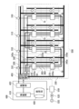
- each solar cell panel 10 e.g., eight solar cell panels 10 are shown in FIG. 4. However, this is for convenience of explanation, and the number and the number of trackers on which the number is mounted are not limited to this).
- a driving device 450 that drives a plurality of solar battery panels 10 is connected to a tracking device 500 that includes the plurality of tracking devices 100, and the driving device 450 includes a plurality of driving devices 450.
- a control device 400 that controls the drive amount of the drive device 450 is connected so that the solar cell panel 10 tracks a preset solar orbit.
- the driving device 450 includes first to third driving devices 450a to 450c.
- the first driving device 450a is, for example, a servo motor, and is connected to the first driving shaft 320, and the first ribbon AT attached to the first end A of the support member 110 of the tracker 100 is attached to the first driving device 450a. It is possible to wind at the first traction point 320a.
- the second driving device 450b is, for example, a servo motor, is connected to the second driving shaft 330, and is a second ribbon attached to the second end B of the support member 110 of the tracker 100.
- the BT can be taken up at the second traction point 330a.
- the third drive device 450c is, for example, a stepping motor, and a wire CT attached to the third end C of the support member 110 of the tracker 100 is connected to the third drive shaft 340 via the third drive shaft 340.
- the traction point 340a can be wound up.
- the control device 400 includes a calculation unit 410, a processing unit 420, and a storage unit 430.
- the control device 400 as tracking information regarding the solar cell panel 10, for example, the latitude, longitude, altitude information of the installation position of the solar cell panel 10, so that the plurality of solar cell panels 10 track a preset solar orbit, Information calculated from the date / time information and the like is stored in the storage unit 430.
- the calculation unit 410 stores the spatial coordinate positions of the support member 110 (for example, the spatial coordinate positions of the first end A, the second end B, and the third end C are determined from the position of the base point D).
- the winding length of the first ribbon AT, the second ribbon BT, and the wire CT is calculated from the tracking information extracted from the unit 430, and an instruction is given to the driving device 450 through the processing unit 420.
- the spatial coordinate position of the support member 110, various tracking information, the information such as the length and thickness of each ribbon and wire to be used, and the driving based on them The calculation of the driving amount supported by the device 450 can be realized by a known technique.
- the power acquired from the plurality of solar cell panels 10 is transmitted through the electric wires 350 and 360. It is sent to the conditioner 510, where the DC power is converted into AC power and transmitted to the transformer 520.
- the transformer 520 transmits the AC power converted by the power conditioner 510 to the power system 1 that is a load.
- the power conditioner 510 has a converter part, an inverter part, and a voltage control part which are not shown in figure.
- the converter unit constitutes a booster circuit that boosts the DC voltage output from the plurality of trackers 100. Further, output voltage data corresponding to the operation instruction information for each tracker 100 is accumulated in the converter unit.
- the inverter unit constitutes an inverter circuit that converts DC power output from the converter unit into AC power.
- the voltage control unit performs MPPT (maximum power point tracking control) control.
- the MPPT control is also called a mountain climbing method, and the voltage control unit adjusts the output voltage of each tracker so that the output power (operating point) of each tracker 100 approaches the maximum power point.
- the electric wires 350 and 360 for acquiring electricity from the solar cell panel 10 are continuously connected to the plurality of trackers 100, and the shadow control unit 310 is a signal line.
- the shadow control unit 310 controls the electrical connection of the electric lines 350 and 360 to the tracker 100 with the power line switching unit 370 in consideration of the shadow portion on the solar cell panel 10.
- the shadow control unit 310 uses the shadow control unit 310 via the processing unit 420 based on the information on the shadow portion of the photovoltaic panel 10 calculated from the tracking information stored in the storage unit 430 by the control unit 400. To give instructions.
- the voltage control based on the MPPT control enables the power line switching unit 370 to appropriately switch to the parallel control of the solar battery panel or the wiring structure in which both the voltage and current are controlled in series. Can be realized.
- two electric wires 350 and 360 are provided to control the influence of the shadow portion of the solar cell panel 10 has been described.
- the performance can be improved by providing three or more electric wires and controlling in stages.
- a heat radiating plate (not shown) that supports the solar cell panel 10 may be provided on the upper surface of the support member 110 on which the solar cell panel 10 is mounted.
- the heat radiating plate can be thermally coupled to the solar cell panel using a metal having a long thermal conductivity such as aluminum or copper, and the temperature that tends to rise in the solar cell panel 10 can be suppressed by the heat radiating structure. .
- the wire CT attached to the third end C of the support member 110 is connected to the third traction point 340a via the third drive shaft 340.
- the configuration example of winding is described, like the first ribbon AT attached to the first end A and the second ribbon BT attached to the second end B. Ribbons can also be used.
- the third drive device 450c can use a servo motor, for example.
- the third drive device 450 c is connected to the third drive shaft 340, and the support member of the tracker 100 is rotated by rotating the third drive shaft 340 in the lateral direction.
- the ribbon attached to the third end C at 110 is allowed to be taken up at the third traction point 340a.
- the photovoltaic power generation apparatus can be provided with a cover 550 made of a transparent member that covers the entire gantry 20.
- a cover 550 made of a transparent member is provided on the gantry 20 so as to cover the whole.
- the cover 550 has the protrusion part 500b so that the inclined surface 500a may be formed in the edge part located in the south side shown in figure, for example.
- the inclined surface 500a is formed with an appropriate surface, a solar power generation device with excellent wind resistance can be realized.
- a solar cell panel that is not a normal tracking is installed below the inclined surface 500a, boosted to a predetermined voltage by MPPT control, and connected in parallel with other solar cell panels, or the current is It is also possible to control and connect in series.
- an inclined surface is appropriately used to improve wind resistance. It is good to provide on the surface.
- the first to ninth tracking are arranged in order from the west side to the east side and from the north side to the south side. Assuming that the device 500 is arranged, the first tracking device 500 is inclined on the north surface and the west surface, the second tracking device 500 is inclined on the north surface, and the third tracking device 500 is inclined on the north surface and the east surface.
- the fourth tracking device 500 has an inclined surface on the west surface
- the fifth tracking device 500 has no inclined surface
- the sixth tracking device 500 has an inclined surface on the east surface
- the seventh tracking device 500 has a south surface and a west surface.
- the eighth tracking device 500 may be provided with an inclined surface on the south surface
- the ninth tracking device 500 may be provided with an inclined surface on the south surface and the east surface.
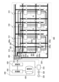
- FIG. 7 shows a configuration example of a solar power generation device including a plurality of tracking devices 500 according to an embodiment of the present invention.
- the drive shaft is divided by forming the connection portion by, for example, a belt and a pulley at the connection portion of the drive shaft connected to each of the drive devices 450a to 450c described above from the outside. It is possible to accurately transmit the driving force by the devices 450a to 450c, and to avoid the influence due to slight height variation and positional deviation that may occur in the photovoltaic power generation device.
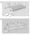
- FIG.8 (a) and (b) are the examples which represented the structure of the solar power generation device provided with the tracking apparatus 500 which concerns on one Embodiment of this invention in three dimensions
- (a) is the said figure, for example 6 shows a three-dimensional example in which a driving device 450 and driving shafts 450a to 450c are added to the configuration example of the photovoltaic power generation apparatus including the one tracking device 500 shown in FIG. 5, and (b) shows, for example, in FIG.
- a configuration example of a solar power generation device including a plurality of tracking devices 500 is three-dimensionally shown.
- FIGS. 8A and 8B are as described above, and the description thereof will not be repeated.
- the tracker 10 which comprises the tracking apparatus 500 which concerns on this embodiment demonstrates the case where 1st ribbon AT and 2nd ribbon BT are used, and can use a ribbon instead of wire CT.
- a double-edged ribbon DT can be used as the ribbon.
- the double-edged ribbon DT has a plurality of teeth 900a on both upper and lower surfaces in the drawing, and the outer side when the double-edged ribbon DT is wound up.
- the interval L1 between the plurality of teeth is larger than the interval L2 between the plurality of teeth on the inner side (corresponding to the upper side in the drawing) when the double-edged ribbon DT is wound.
- the interval L3 between the plurality of teeth on the outer side when the ribbon with double blades is wound (the distance between the upper surfaces of adjacent teeth) is before the ribbon with double blades is wound. It is equal to the space
- the present invention is useful for a distributed solar tracking device applied to a solar power generation device.
Landscapes
- Life Sciences & Earth Sciences (AREA)
- Sustainable Development (AREA)
- Photovoltaic Devices (AREA)
Abstract
L'invention concerne un dispositif de génération d'énergie solaire comprenant : une pluralité de panneaux de cellules solaires ; un dispositif d'entraînement destiné à entraîner la pluralité de panneaux de cellules solaires ; une unité de commande destinée à commander le montant de l'entraînement de telle sorte que la pluralité de panneaux de cellules solaires peuvent suivre l'orbite du soleil ; et une pluralité d'unités de poursuite sur lesquelles sont respectivement montés la pluralité de panneaux de cellules solaires. Chacune de la pluralité d'unités de poursuite est pourvue d'un élément support en forme de T servant au montage des panneaux de cellules solaires et d'un mécanisme de poursuite couplé à l'élément support. Sur la base du montant d'entraînement commandé, les trois extrémités du T de l'élément support sont entraînées pour amener les panneaux de cellules solaires à poursuivre l'orbite du soleil.
Priority Applications (1)
| Application Number | Priority Date | Filing Date | Title |
|---|---|---|---|
| JP2017530850A JPWO2017018367A1 (ja) | 2015-07-28 | 2016-07-25 | 太陽光発電装置 |
Applications Claiming Priority (2)
| Application Number | Priority Date | Filing Date | Title |
|---|---|---|---|
| JP2015-148510 | 2015-07-28 | ||
| JP2015148510 | 2015-07-28 |
Publications (1)
| Publication Number | Publication Date |
|---|---|
| WO2017018367A1 true WO2017018367A1 (fr) | 2017-02-02 |
Family
ID=57884722
Family Applications (1)
| Application Number | Title | Priority Date | Filing Date |
|---|---|---|---|
| PCT/JP2016/071677 Ceased WO2017018367A1 (fr) | 2015-07-28 | 2016-07-25 | Dispositif de génération d'énergie solaire |
Country Status (2)
| Country | Link |
|---|---|
| JP (1) | JPWO2017018367A1 (fr) |
| WO (1) | WO2017018367A1 (fr) |
Citations (8)
| Publication number | Priority date | Publication date | Assignee | Title |
|---|---|---|---|---|
| US20110000543A1 (en) * | 2009-07-02 | 2011-01-06 | Errico Joseph P | Solar energy collection and conversion system |
| JP2011091450A (ja) * | 2011-02-07 | 2011-05-06 | Nikkeikin Aluminium Core Technology Co Ltd | 太陽電池パネル |
| JP2013089844A (ja) * | 2011-10-20 | 2013-05-13 | Panasonic Corp | 追尾型太陽電池装置 |
| JP2013110252A (ja) * | 2011-11-21 | 2013-06-06 | Etsuya Shinagawa | 自動太陽追尾装置付太陽エネルギー収集システム |
| JP2013529849A (ja) * | 2010-06-29 | 2013-07-22 | スマート フラワー エナジー テクノロジー ゲゼルシャフト ミット ベシュレンクテル ハフツング | 折り畳み式のソーラーモジュール |
| JP2014505374A (ja) * | 2011-02-10 | 2014-02-27 | エタネジー リミテッド | 位置決めシステム |
| JP2015095146A (ja) * | 2013-11-13 | 2015-05-18 | 伸和工業株式会社 | 太陽光発電システム |
| JP2015518703A (ja) * | 2012-04-26 | 2015-07-02 | ジュ リ,ソン | 太陽光発電用追跡装置 |
-
2016
- 2016-07-25 WO PCT/JP2016/071677 patent/WO2017018367A1/fr not_active Ceased
- 2016-07-25 JP JP2017530850A patent/JPWO2017018367A1/ja active Pending
Patent Citations (8)
| Publication number | Priority date | Publication date | Assignee | Title |
|---|---|---|---|---|
| US20110000543A1 (en) * | 2009-07-02 | 2011-01-06 | Errico Joseph P | Solar energy collection and conversion system |
| JP2013529849A (ja) * | 2010-06-29 | 2013-07-22 | スマート フラワー エナジー テクノロジー ゲゼルシャフト ミット ベシュレンクテル ハフツング | 折り畳み式のソーラーモジュール |
| JP2011091450A (ja) * | 2011-02-07 | 2011-05-06 | Nikkeikin Aluminium Core Technology Co Ltd | 太陽電池パネル |
| JP2014505374A (ja) * | 2011-02-10 | 2014-02-27 | エタネジー リミテッド | 位置決めシステム |
| JP2013089844A (ja) * | 2011-10-20 | 2013-05-13 | Panasonic Corp | 追尾型太陽電池装置 |
| JP2013110252A (ja) * | 2011-11-21 | 2013-06-06 | Etsuya Shinagawa | 自動太陽追尾装置付太陽エネルギー収集システム |
| JP2015518703A (ja) * | 2012-04-26 | 2015-07-02 | ジュ リ,ソン | 太陽光発電用追跡装置 |
| JP2015095146A (ja) * | 2013-11-13 | 2015-05-18 | 伸和工業株式会社 | 太陽光発電システム |
Also Published As
| Publication number | Publication date |
|---|---|
| JPWO2017018367A1 (ja) | 2018-05-17 |
Similar Documents
| Publication | Publication Date | Title |
|---|---|---|
| Fathabadi | Novel high efficient offline sensorless dual-axis solar tracker for using in photovoltaic systems and solar concentrators | |
| Seme et al. | Dual-axis photovoltaic tracking system–Design and experimental investigation | |
| EP2543879B1 (fr) | Appareil de générateur solaire avec suivi commandé par câble | |
| US9455665B1 (en) | Solar tracker cleaning system and method | |
| KR100998337B1 (ko) | 수상 태양광 발전장치 | |
| JP4955194B2 (ja) | 太陽光発電システム | |
| KR101184425B1 (ko) | 태양광 발전용 추적장치 | |
| KR100864215B1 (ko) | 다수의 크랭크축을 이용한 태양광 발전장치 | |
| US10680127B2 (en) | Power generation circuit unit | |
| JP2016092969A (ja) | 角度可変形太陽光発電システム | |
| JP5617061B2 (ja) | 太陽光発電パネルユニット及び太陽光発電装置 | |
| KR20140028179A (ko) | 태양추적 발전이 가능한 빌딩 회전형 태양광 발전소 | |
| IT7949466A0 (it) | Apparecchio collettore di energia solare per la trasformazione in calore in un liquido | |
| JP2016103952A (ja) | 太陽光発電装置 | |
| JP2016183800A (ja) | 太陽光集光システムおよびヘリオスタット | |
| JP2018074832A (ja) | 太陽光発電装置 | |
| JPWO2017018367A1 (ja) | 太陽光発電装置 | |
| KR20190000481A (ko) | 태양광 발전장치 | |
| KR20100022540A (ko) | 태양전지판의 각도조절장치 | |
| KR20200004066A (ko) | 태양광발전모듈을 구비한 스마트 팜 | |
| KR20140005878U (ko) | 태양광 경사 가변형 구조물 | |
| US9732987B2 (en) | Two axis solar tracking system | |
| CN115247627B (zh) | 一种基于虚拟电厂的分布式电能调节装置 | |
| KR102151850B1 (ko) | 모듈화된 태양광 추적 장치 | |
| WO2018079677A1 (fr) | Dispositif générateur d'énergie solaire concentrée |
Legal Events
| Date | Code | Title | Description |
|---|---|---|---|
| 121 | Ep: the epo has been informed by wipo that ep was designated in this application |
Ref document number: 16830472 Country of ref document: EP Kind code of ref document: A1 |
|
| ENP | Entry into the national phase |
Ref document number: 2017530850 Country of ref document: JP Kind code of ref document: A |
|
| NENP | Non-entry into the national phase |
Ref country code: DE |
|
| 122 | Ep: pct application non-entry in european phase |
Ref document number: 16830472 Country of ref document: EP Kind code of ref document: A1 |