WO2017018367A1 - 太陽光発電装置 - Google Patents
太陽光発電装置 Download PDFInfo
- Publication number
- WO2017018367A1 WO2017018367A1 PCT/JP2016/071677 JP2016071677W WO2017018367A1 WO 2017018367 A1 WO2017018367 A1 WO 2017018367A1 JP 2016071677 W JP2016071677 W JP 2016071677W WO 2017018367 A1 WO2017018367 A1 WO 2017018367A1
- Authority
- WO
- WIPO (PCT)
- Prior art keywords
- power generation
- generation device
- solar power
- ribbon
- solar
- Prior art date
- Legal status (The legal status is an assumption and is not a legal conclusion. Google has not performed a legal analysis and makes no representation as to the accuracy of the status listed.)
- Ceased
Links
Images



Classifications
-
- H—ELECTRICITY
- H02—GENERATION; CONVERSION OR DISTRIBUTION OF ELECTRIC POWER
- H02S—GENERATION OF ELECTRIC POWER BY CONVERSION OF INFRARED RADIATION, VISIBLE LIGHT OR ULTRAVIOLET LIGHT, e.g. USING PHOTOVOLTAIC [PV] MODULES
- H02S20/00—Supporting structures for PV modules
- H02S20/30—Supporting structures being movable or adjustable, e.g. for angle adjustment
- H02S20/32—Supporting structures being movable or adjustable, e.g. for angle adjustment specially adapted for solar tracking
-
- Y—GENERAL TAGGING OF NEW TECHNOLOGICAL DEVELOPMENTS; GENERAL TAGGING OF CROSS-SECTIONAL TECHNOLOGIES SPANNING OVER SEVERAL SECTIONS OF THE IPC; TECHNICAL SUBJECTS COVERED BY FORMER USPC CROSS-REFERENCE ART COLLECTIONS [XRACs] AND DIGESTS
- Y02—TECHNOLOGIES OR APPLICATIONS FOR MITIGATION OR ADAPTATION AGAINST CLIMATE CHANGE
- Y02E—REDUCTION OF GREENHOUSE GAS [GHG] EMISSIONS, RELATED TO ENERGY GENERATION, TRANSMISSION OR DISTRIBUTION
- Y02E10/00—Energy generation through renewable energy sources
- Y02E10/50—Photovoltaic [PV] energy
Definitions
- a solar power generation apparatus that generates power using solar energy.
- a solar power generation device with a tracking device that performs tracking control for driving a solar cell panel so as to track a preset solar orbit.
- the tracking device generally includes a drive device that drives a solar cell panel, and a control unit that controls the drive of the drive device by calculating a drive amount of the drive device so as to match a preset solar orbit. .
- an object of the present invention is to provide a photovoltaic power generation apparatus that includes a tracking device that is a distributed movable type, has excellent convenience during installation and portability during transportation, and can be realized at low cost. It is.
- a plurality of solar panels arranged in an array and converting sunlight into electric power;
- a driving device for driving a plurality of solar cell panels;
- a control device for controlling the drive amount of the drive device so that a plurality of solar battery panels track a preset solar trajectory;
- a photovoltaic power generation device including a tracking device,
- the tracking device Provided with a plurality of trackers each mounting a plurality of solar cell panels, Each of the plurality of trackers A holding member for mounting the solar cell panel;
- a tracking mechanism connected to the holding member, Based on the controlled driving amount of the driving device, the solar panel tracks a preset solar trajectory by driving at least three points on the holding member. It is characterized by that.
- each of the trackers on which the solar cell panel is mounted can be driven by the drive device. Moreover, the solar cell panel can be accurately tracked to the solar orbit by the structure in which at least three points of the holding member are driven.
- a solar power generation apparatus including a solar tracking apparatus that is of a distributed movable type and has a simple structure and can be realized at low cost can be realized.
- the drive device includes at least three drive units that respectively drive at least three points of the holding member. It is preferable.
- the solar cell panel can be accurately tracked in the solar orbit with a simple structure.
- the first driving unit includes a first motor that winds the first ribbon
- the second drive unit comprises a second motor that winds the second ribbon
- the third driving unit includes a load applying member that applies a load to the remaining third driving point among the three points.
- the control device Controlling the amount of winding of each of the first motor and the second motor, and controlling the load applied by the load applying member; It is preferable.
- the remaining one of the three points may be driven, for example, when returning from the position where the other two points are driven, so that it is different from the control of the other two points. It can be realized with a structure that does not require precise position control.
- a wire, a wire with a spring interposed, or a constant load spring is attached as a load applying member. It may be.
- a third ribbon is attached to the third driving point instead of the load applying member. It may be.
- the third ribbon can also be wound up by rotation.
- a double-edged ribbon having a plurality of teeth on both sides is selectively used as the first ribbon, the second ribbon, and the third ribbon.
- the interval between the plurality of teeth on the outside when the double-edged ribbon is wound is equal to the interval between the plurality of teeth on the inner side of the linear state before the double-edged ribbon is wound. It is preferable.
- the tracking mechanism A column supporting the holding member; With a base part that supports the column part, A ring for connecting the holding member and the support column is further provided; It is preferable.
- the holding member and the support column are connected by the ring, the holding member is driven smoothly through the ring. As a result, the solar cell panel can be more accurately tracked in the solar orbit.
- the tracking mechanism A first guide and a second guide that respectively pass the first ribbon and the second ribbon are provided in the base portion. It is preferable.
- first and second ribbons can be accurately wound through the first and second guides, and the wire can be accurately wound through the opening of the protrusion.
- the support column is provided with a pair of shoulders that limit the drive amount of the support member. It is preferable.
- the tracking mechanism It further includes a wall part that holds the lower part of the column part so as to cover it,
- the base part is provided with a groove part that can store the column part,
- the strut is While using the tracker, while standing upright by the penetrating member that penetrates the support column from the wall portion, when the tracker is transported, it is accommodated in the groove portion by removing and tilting the penetrating member. It is preferable.
- At least a first electric line and a second electric line connected to a plurality of trackers and acquiring electricity from the solar cell panel; In consideration of the shaded area on the solar cell panel via a signal line continuously connected to each of the trackers arranged in one of two directions perpendicularly intersecting among the plurality of trackers.
- a shadow control unit for controlling electrical connection of the first electric line and the second electric line to the tracker It is preferable.
- a platform with a tracking device A rectangular case made of a transparent member provided to cover the entire tracking device on the gantry, and further includes At least one side of the case is inclined, It is preferable.
- a plurality of tracking devices connected to each other, One control device drives a plurality of tracking devices via the drive device. It is preferable.
- a plurality of tracking devices can be centrally controlled via a single control device, and a solar power generation device including a plurality of tracking devices with a simple structure can be realized.
- a photovoltaic power generation apparatus that is of a distributed movable type, has excellent convenience during installation and portability during transportation, and includes a tracking device that can be realized at low cost.
- FIG. 1 shows a structure of a tracking device constituting a tracking device according to an embodiment of the present invention, in a folded state, and (a) is a diagram viewed from substantially above the tracking device; ) Is a view of the tracker viewed from a substantially lateral direction. It is a figure which shows the example of a wiring and a transmission shaft structure for implement
- (A) is a figure which shows the structural example of the ribbon used for the tracker concerning one Embodiment of this invention, Comprising: It is a figure of the linear state before winding up, (b) is based on one Embodiment of this invention. It is a figure which shows the structural example of the ribbon used for a tracker, Comprising: It is a figure of the state at the time of winding up.
- the tracking device 500 includes a plurality of trackers 100 each having a size of, for example, about 10 cm to 50 cm square, on which each of the solar cell panels 10 arranged in an array is mounted. It has.
- the tracking device 500 is disposed on the gantry 20 provided on the base 40 via the support column 30.
- the size of the tracking device 500 is, for example, about 1 m ⁇ 2 m.
- the gantry 20 shows an example in which each of the solar cell panels 10 mounted on the tracking device 100 is inclined upward toward the north side, but is not inclined or inclined in other directions. It may be.
- the number of the solar cell panels 10 arranged in an array, the size of the tracker 100, and the size of the tracking device 500 are shown here as examples, and are shown in FIG. It is not limited to things.
- the solar power generation device includes, for example, a tracking device 500 including a plurality of the tracking units 100 illustrated in FIG. 2 on which the solar cell panel 10 is mounted, and further drives the plurality of solar cell panels 10, for example, as illustrated in FIG.
- the driving device 450 includes a control device 400 shown in FIG. 4 for controlling the driving amount of the driving device 450 so that the plurality of solar battery panels 10 track a preset solar orbit.
- FIG. 2 specifically shows the structure of the tracker 100 constituting the tracking device 500 in the present embodiment.
- the tracker 100 includes, for example, a T-shaped holding member 110 (consisting of a 110a portion and a 110b portion) on which the solar cell panel 10 is mounted, and a tracking mechanism connected to the holding member 110. It has.
- the tracking mechanism is installed and used on the gantry 20 shown in FIG. 1 with the solar cell panel 10 mounted on the holding member 110 to be connected.
- the tracker 100 drives the solar cell panel 10 in advance by driving at least three points in the holding member 110 based on the controlled driving amount of the driving device 450. It is configured to track the trajectory.
- a T-shaped member is used as an example of the shape of the holding member 110.
- three end portions first driving point to first driving point
- the first end A and the second end B as a pair of opposing ends of the first ribbon A and the second end B of FIG.
- the second ribbon BT is attached by, for example, a screw, and a wire CT is attached to the third end C as the remaining end via an opening Ch, for example.
- the driving device 450 shown in FIG. 4 includes, for example, a first motor 450a and a second motor 450c, which are, for example, servomotors for winding the first ribbon AT and the second ribbon BT, and the wires.
- a third motor 450b which is a stepping motor for winding is provided.
- the control device 400 controls the amount of winding of each of the first motor 450a, the second motor 450c, and the third motor 450b.
- a constant load spring for applying a constant load can be provided instead of the third motor 450b. In this case, the tip of the constant load spring is not provided with the wire CT. You may make it attach to the part C.
- the solar power generation device including the tracking device 500 can drive each of the trackers 100 on which the solar cell panel 10 is mounted by the driving device 450. That is, the solar cell panel can be accurately tracked in the solar orbit by the structure in which the positions of the three points on the holding member 110 are controlled and driven.
- a photovoltaic power generation apparatus including the tracking device 500 that is a distributed movable type has a simple structure, and can be realized at low cost can be realized.
- a plurality of solar battery panels 10 can be centrally controlled by a single control device 400 via a plurality of trackers 100, and a solar power generation device including a tracking device 500 having a simple structure is realized. can do.
- this embodiment demonstrated the case where the shape of the holding member 110 was T-shaped, this invention is not limited to this shape, Various shapes may be sufficient, and the solar cell panel 10 is shown. Any member that can be mounted and that can be driven by controlling the positions of at least three of them may be used. Further, as in this embodiment, the number of points that are driven by controlling the position is not limited to three points, but may be four or more points, and the number of ribbons, wires, and the like appropriately according to the number. Can also be increased.
- the tracking mechanism includes a support column 150 that supports the holding member 110 and a base unit 210 that supports the support unit 150, and the base unit 210 is attached to the attachment unit 200. It is installed on the gantry 20 via
- the attachment unit 200 is shown as being provided in one set corresponding to the tracker 100, but a plurality of trackers 100 are connected and installed on the gantry 20,
- the attachment part 200 has a stretched structure.
- the support column 10 is integrally formed with a head 130 having an opening and a shoulder 140 continuous with the head 130.
- the holding member 110 and the support column 150 are coupled to each other so that the ring 120 passing through the opening in the head 130 is connected to the bottom of the support column 150.
- the driving of the holding member 110 is smoothly performed via the ring 120.
- the solar cell panel 10 can be more accurately tracked in the solar orbit.
- the base 210 includes a first guide 190a and a second guide 190b through which the first ribbon AT and the second ribbon BT pass, respectively, and a protruding portion having an opening through which the wire CT passes.
- the first ribbon AT and the second ribbon BT can be accurately wound through the first guide 190a and the second guide 190b.
- the wire CT can be accurately wound through the opening 230C of the protruding portion 230.
- the first ribbon AT, the second ribbon BT, and the wire CT are connected to, for example, the first traction point 320a, the second traction point 330a, and the third traction point 340a of FIG. It is driven by the driving amount of the driving device 450 controlled by the control device 400.
- the support column 150 is provided with a pair of shoulder portions 140 that limit the drive amount of the support member 110.
- the support member 110 tracks the solar orbit set in advance by the solar cell panel 10 by winding the first ribbon AT, the second ribbon BT, and the wire CT with controlled drive amounts.
- the shoulder 140 is, for example, a ring in which one of the first end A and the second end B, which is a pair of ends, connects the support member 110 according to the driving amount.
- 120 moves in the opening part of the head part 130 along the moving direction of a pair of edge part, it has a role which stops that the support member 110 whole falls down.
- the shoulder 140 has a shape protruding in the left-right direction (defined as) perpendicular to the up-down direction (defined as) from the support 150 to the head 130.
- the angle with respect to the up-down direction in the left-right direction of the shape that protrudes may be a shape that protrudes at an angle that can prevent the support member 110 from falling, for example, in addition to a vertical shape, and is particularly limited. It is not a thing.
- the tracker 100 is further formed with a wall portion 155 that holds the lower portion of the support column 150 from, for example, three directions.
- the base part 210 is provided with a groove part 210h in which the support part 150 can be accommodated.
- the support part 150 can be used to remove the support part 150 from the wall part 155 when the tracker 100 is used as a solar power generation device.
- a penetrating member 220t for example, a screw
- the penetrating member 220t is removed, for example, as viewed from above in FIG. 3A and the side of FIG. 3B.
- the pair of support portions 170r at the bottom of the wall portion 155 can be accommodated in the groove portion 210h by being tilted through a structure in which the rotation structure 160s at the bottom of the support column 150 is sandwiched.
- the support unit 150 is housed in the groove portion 210h, so that the entire tracker 100 is folded in a compact form. In addition to being extremely excellent, it is also very convenient for installation.
- each solar cell panel 10 e.g., eight solar cell panels 10 are shown in FIG. 4. However, this is for convenience of explanation, and the number and the number of trackers on which the number is mounted are not limited to this).
- a driving device 450 that drives a plurality of solar battery panels 10 is connected to a tracking device 500 that includes the plurality of tracking devices 100, and the driving device 450 includes a plurality of driving devices 450.
- a control device 400 that controls the drive amount of the drive device 450 is connected so that the solar cell panel 10 tracks a preset solar orbit.
- the driving device 450 includes first to third driving devices 450a to 450c.
- the first driving device 450a is, for example, a servo motor, and is connected to the first driving shaft 320, and the first ribbon AT attached to the first end A of the support member 110 of the tracker 100 is attached to the first driving device 450a. It is possible to wind at the first traction point 320a.
- the second driving device 450b is, for example, a servo motor, is connected to the second driving shaft 330, and is a second ribbon attached to the second end B of the support member 110 of the tracker 100.
- the BT can be taken up at the second traction point 330a.
- the third drive device 450c is, for example, a stepping motor, and a wire CT attached to the third end C of the support member 110 of the tracker 100 is connected to the third drive shaft 340 via the third drive shaft 340.
- the traction point 340a can be wound up.
- the control device 400 includes a calculation unit 410, a processing unit 420, and a storage unit 430.
- the control device 400 as tracking information regarding the solar cell panel 10, for example, the latitude, longitude, altitude information of the installation position of the solar cell panel 10, so that the plurality of solar cell panels 10 track a preset solar orbit, Information calculated from the date / time information and the like is stored in the storage unit 430.
- the calculation unit 410 stores the spatial coordinate positions of the support member 110 (for example, the spatial coordinate positions of the first end A, the second end B, and the third end C are determined from the position of the base point D).
- the winding length of the first ribbon AT, the second ribbon BT, and the wire CT is calculated from the tracking information extracted from the unit 430, and an instruction is given to the driving device 450 through the processing unit 420.
- the spatial coordinate position of the support member 110, various tracking information, the information such as the length and thickness of each ribbon and wire to be used, and the driving based on them The calculation of the driving amount supported by the device 450 can be realized by a known technique.
- the power acquired from the plurality of solar cell panels 10 is transmitted through the electric wires 350 and 360. It is sent to the conditioner 510, where the DC power is converted into AC power and transmitted to the transformer 520.
- the transformer 520 transmits the AC power converted by the power conditioner 510 to the power system 1 that is a load.
- the power conditioner 510 has a converter part, an inverter part, and a voltage control part which are not shown in figure.
- the converter unit constitutes a booster circuit that boosts the DC voltage output from the plurality of trackers 100. Further, output voltage data corresponding to the operation instruction information for each tracker 100 is accumulated in the converter unit.
- the inverter unit constitutes an inverter circuit that converts DC power output from the converter unit into AC power.
- the voltage control unit performs MPPT (maximum power point tracking control) control.
- the MPPT control is also called a mountain climbing method, and the voltage control unit adjusts the output voltage of each tracker so that the output power (operating point) of each tracker 100 approaches the maximum power point.
- the electric wires 350 and 360 for acquiring electricity from the solar cell panel 10 are continuously connected to the plurality of trackers 100, and the shadow control unit 310 is a signal line.
- the shadow control unit 310 controls the electrical connection of the electric lines 350 and 360 to the tracker 100 with the power line switching unit 370 in consideration of the shadow portion on the solar cell panel 10.
- the shadow control unit 310 uses the shadow control unit 310 via the processing unit 420 based on the information on the shadow portion of the photovoltaic panel 10 calculated from the tracking information stored in the storage unit 430 by the control unit 400. To give instructions.
- the voltage control based on the MPPT control enables the power line switching unit 370 to appropriately switch to the parallel control of the solar battery panel or the wiring structure in which both the voltage and current are controlled in series. Can be realized.
- two electric wires 350 and 360 are provided to control the influence of the shadow portion of the solar cell panel 10 has been described.
- the performance can be improved by providing three or more electric wires and controlling in stages.
- a heat radiating plate (not shown) that supports the solar cell panel 10 may be provided on the upper surface of the support member 110 on which the solar cell panel 10 is mounted.
- the heat radiating plate can be thermally coupled to the solar cell panel using a metal having a long thermal conductivity such as aluminum or copper, and the temperature that tends to rise in the solar cell panel 10 can be suppressed by the heat radiating structure. .
- the wire CT attached to the third end C of the support member 110 is connected to the third traction point 340a via the third drive shaft 340.
- the configuration example of winding is described, like the first ribbon AT attached to the first end A and the second ribbon BT attached to the second end B. Ribbons can also be used.
- the third drive device 450c can use a servo motor, for example.
- the third drive device 450 c is connected to the third drive shaft 340, and the support member of the tracker 100 is rotated by rotating the third drive shaft 340 in the lateral direction.
- the ribbon attached to the third end C at 110 is allowed to be taken up at the third traction point 340a.
- the photovoltaic power generation apparatus can be provided with a cover 550 made of a transparent member that covers the entire gantry 20.
- a cover 550 made of a transparent member is provided on the gantry 20 so as to cover the whole.
- the cover 550 has the protrusion part 500b so that the inclined surface 500a may be formed in the edge part located in the south side shown in figure, for example.
- the inclined surface 500a is formed with an appropriate surface, a solar power generation device with excellent wind resistance can be realized.
- a solar cell panel that is not a normal tracking is installed below the inclined surface 500a, boosted to a predetermined voltage by MPPT control, and connected in parallel with other solar cell panels, or the current is It is also possible to control and connect in series.
- an inclined surface is appropriately used to improve wind resistance. It is good to provide on the surface.
- the first to ninth tracking are arranged in order from the west side to the east side and from the north side to the south side. Assuming that the device 500 is arranged, the first tracking device 500 is inclined on the north surface and the west surface, the second tracking device 500 is inclined on the north surface, and the third tracking device 500 is inclined on the north surface and the east surface.
- the fourth tracking device 500 has an inclined surface on the west surface
- the fifth tracking device 500 has no inclined surface
- the sixth tracking device 500 has an inclined surface on the east surface
- the seventh tracking device 500 has a south surface and a west surface.
- the eighth tracking device 500 may be provided with an inclined surface on the south surface
- the ninth tracking device 500 may be provided with an inclined surface on the south surface and the east surface.
- FIG. 7 shows a configuration example of a solar power generation device including a plurality of tracking devices 500 according to an embodiment of the present invention.
- the drive shaft is divided by forming the connection portion by, for example, a belt and a pulley at the connection portion of the drive shaft connected to each of the drive devices 450a to 450c described above from the outside. It is possible to accurately transmit the driving force by the devices 450a to 450c, and to avoid the influence due to slight height variation and positional deviation that may occur in the photovoltaic power generation device.
- FIG.8 (a) and (b) are the examples which represented the structure of the solar power generation device provided with the tracking apparatus 500 which concerns on one Embodiment of this invention in three dimensions
- (a) is the said figure, for example 6 shows a three-dimensional example in which a driving device 450 and driving shafts 450a to 450c are added to the configuration example of the photovoltaic power generation apparatus including the one tracking device 500 shown in FIG. 5, and (b) shows, for example, in FIG.
- a configuration example of a solar power generation device including a plurality of tracking devices 500 is three-dimensionally shown.
- FIGS. 8A and 8B are as described above, and the description thereof will not be repeated.
- the tracker 10 which comprises the tracking apparatus 500 which concerns on this embodiment demonstrates the case where 1st ribbon AT and 2nd ribbon BT are used, and can use a ribbon instead of wire CT.
- a double-edged ribbon DT can be used as the ribbon.
- the double-edged ribbon DT has a plurality of teeth 900a on both upper and lower surfaces in the drawing, and the outer side when the double-edged ribbon DT is wound up.
- the interval L1 between the plurality of teeth is larger than the interval L2 between the plurality of teeth on the inner side (corresponding to the upper side in the drawing) when the double-edged ribbon DT is wound.
- the interval L3 between the plurality of teeth on the outer side when the ribbon with double blades is wound (the distance between the upper surfaces of adjacent teeth) is before the ribbon with double blades is wound. It is equal to the space
- the present invention is useful for a distributed solar tracking device applied to a solar power generation device.
Landscapes
- Life Sciences & Earth Sciences (AREA)
- Sustainable Development (AREA)
- Photovoltaic Devices (AREA)
Abstract
【課題】 【解決手段】太陽光発電装置は、複数の太陽電池パネルと、複数の太陽電池パネルを駆動する駆動装置と、複数の太陽電池パネルが太陽軌道を追尾するように上記駆動量を制御する制御部と、複数の太陽電池パネルの各々を搭載する複数の追尾子とを備え、複数の追尾子の各々は、太陽電池パネルを搭載するT字状の保持部材と、保持部材に連結する追尾機構と、を備える。制御された駆動量に基づいて、保持部材のT字状の3つの端部を駆動することにより、太陽電池パネルが太陽軌道を追尾する。
Description
従来から、太陽エネルギーを利用して電力を発生させる太陽光発電装置が知られている。また、予め設定された太陽軌道を追尾するように太陽電池パネルを駆動させる追尾制御を行う追尾装置付きの太陽光発電装置も知られている。追尾装置は、一般に、太陽電池パネルを駆動する駆動装置と、該駆動装置の駆動量を予め設定された太陽軌道に合うように算出して駆動装置の駆動を制御する制御部とを備えている。
一般的な追尾装置は、装置が大きく、大きい割には太陽電池積載量も多くない。これは耐風性に優れた構造を実現する必要があるからである。そのため、分散可動型追尾装置も幾つか提案されているが、機構が複雑であり、コストが高くつく。さらには、当該追尾装置の設置時や搬送時の不具合が大きい。
かかる点に鑑み、本発明の目的は、分散可動型であって、設置時の利便性や搬送時の可搬性に優れ、低コストで実現できる追尾装置を備えた太陽光発電装置を提供することである。
上記の目的を実現するために、本発明の一側面に係る太陽光発電装置は、
アレイ状に配置され、太陽光を電力に変換する複数の太陽電池パネルと、
複数の太陽電池パネルを駆動する駆動装置と、
複数の太陽電池パネルが予め設定された太陽軌道を追尾するように駆動装置の駆動量を制御する制御装置と、
追尾装置とを含む太陽光発電装置であって、
追尾装置は、
複数の太陽電池パネルの各々を搭載する複数の追尾子を備え、
複数の追尾子の各々は、
太陽電池パネルを搭載する保持部材と、
保持部材に連結する追尾機構とを備え、
駆動装置の制御された駆動量に基づいて、保持部材における少なくとも3点を駆動することにより、太陽電池パネルが予め設定された太陽軌道を追尾する、
ことを特徴とする。
アレイ状に配置され、太陽光を電力に変換する複数の太陽電池パネルと、
複数の太陽電池パネルを駆動する駆動装置と、
複数の太陽電池パネルが予め設定された太陽軌道を追尾するように駆動装置の駆動量を制御する制御装置と、
追尾装置とを含む太陽光発電装置であって、
追尾装置は、
複数の太陽電池パネルの各々を搭載する複数の追尾子を備え、
複数の追尾子の各々は、
太陽電池パネルを搭載する保持部材と、
保持部材に連結する追尾機構とを備え、
駆動装置の制御された駆動量に基づいて、保持部材における少なくとも3点を駆動することにより、太陽電池パネルが予め設定された太陽軌道を追尾する、
ことを特徴とする。
上記太陽光発電装置によると、太陽電池パネルを搭載する追尾子の各々を駆動装置により駆動させることができる。また、保持部材の少なくとも3点を駆動させる構造により、太陽電池パネルを正確に太陽軌道に追尾させることができる。このように、分散可動型であって、簡易な構造で、低コストで実現できる太陽光追尾装置を備えた太陽光発電装置を実現することができる。
本実施形態に係る太陽光発電装置において、
駆動装置は、保持部材の少なくとも3点をそれぞれ駆動する少なくとも3つの駆動部よりなる、
ことが好ましい。
駆動装置は、保持部材の少なくとも3点をそれぞれ駆動する少なくとも3つの駆動部よりなる、
ことが好ましい。
このように、3つの駆動部により、保持部材の3点を駆動させることにより、簡易な構造で、太陽電池パネルを正確に太陽軌道に追尾させることができる。
本実施形態に係る太陽光発電装置において、
追尾子の各々は、
保持部材における3点のうちの少なくとも第1の駆動点及び第2の駆動点には、第1のリボン及び第2のリボンがそれぞれ取り付けられており、
駆動装置において、
第1の駆動部は、第1のリボンの巻き取りを行う第1のモーターよりなり、
第2の駆動部は、第2のリボンの巻き取りを行う第2のモーターよりなり、
第3の駆動部は、3点のうちの残りの第3の駆動点に荷重を付与する荷重付与部材とを備え、
制御装置は、
第1のモーター、第2のモーターの各々の巻き取り量を制御すると共に、荷重付与部材が付与する荷重を制御する、
ことが好ましい。
追尾子の各々は、
保持部材における3点のうちの少なくとも第1の駆動点及び第2の駆動点には、第1のリボン及び第2のリボンがそれぞれ取り付けられており、
駆動装置において、
第1の駆動部は、第1のリボンの巻き取りを行う第1のモーターよりなり、
第2の駆動部は、第2のリボンの巻き取りを行う第2のモーターよりなり、
第3の駆動部は、3点のうちの残りの第3の駆動点に荷重を付与する荷重付与部材とを備え、
制御装置は、
第1のモーター、第2のモーターの各々の巻き取り量を制御すると共に、荷重付与部材が付与する荷重を制御する、
ことが好ましい。
このようにすると、3点のうちの残りの一点は、例えば他の2点が駆動された位置から元に戻すような場合に駆動させればよいので、上記他の2点の制御とは異なって精密な位置制御が不要でもよい構造で実現可能である。
本実施形態に係る太陽光発電装置において、
第3の駆動点には、荷重付与部材として、ワイヤ、バネを介在させたワイヤ、又は定荷重バネが取り付けられている、
ことであってもよい。
第3の駆動点には、荷重付与部材として、ワイヤ、バネを介在させたワイヤ、又は定荷重バネが取り付けられている、
ことであってもよい。
本実施形態に係る太陽光発電装置において、
第3の駆動点には、荷重付与部材の代わりに、第3のリボンが取り付けられている、
ことであってもよい。
第3の駆動点には、荷重付与部材の代わりに、第3のリボンが取り付けられている、
ことであってもよい。
このようにすると、第1のリボン及び第2のリボンに加えて、第3のリボンも回転での巻き取りができる。
本実施形態に係る太陽光発電装置において、
第1のリボン、第2のリボン及び第3のリボンとして、選択的に、両側の面に複数の歯を設けた両刃付きリボンが用いられ、
両刃付きリボンが巻き取られた際の外側における複数の歯の間隔は、両刃付きリボンが巻き取られる前の直線上状態の内側における複数の歯の間隔と等しい、
ことが好ましい。
第1のリボン、第2のリボン及び第3のリボンとして、選択的に、両側の面に複数の歯を設けた両刃付きリボンが用いられ、
両刃付きリボンが巻き取られた際の外側における複数の歯の間隔は、両刃付きリボンが巻き取られる前の直線上状態の内側における複数の歯の間隔と等しい、
ことが好ましい。
このようにすると、リボンの滑りによる撓みをより抑制することができる。
本実施形態に係る太陽光発電装置において、
追尾機構は、
保持部材を支える支柱部と、
支柱部を支える土台部とを備え、
保持部材と支柱部とを連結するリングがさらに設けられている、
ことが好ましい。
追尾機構は、
保持部材を支える支柱部と、
支柱部を支える土台部とを備え、
保持部材と支柱部とを連結するリングがさらに設けられている、
ことが好ましい。
このようにすると、保持部材と支柱部とがリングによって連結しているため、リングを介して保持部材の駆動が円滑に行われる。その結果、太陽電池パネルをより正確に太陽軌道に追尾させることができる。
本実施形態に係る太陽光発電装置において、
追尾機構は、
土台部内に、第1のリボン及び第2のリボンをそれぞれ通す第1のガイド及び第2のガイドを備えている、
ことが好ましい。
追尾機構は、
土台部内に、第1のリボン及び第2のリボンをそれぞれ通す第1のガイド及び第2のガイドを備えている、
ことが好ましい。
このようにすると、第1及び第2のリボンが第1及び第2のガイドを通じて正確に巻き取られることが可能となり、また、ワイヤーが突き出し部の開口部を通じて正確に巻き取られることが可能となる。
本実施形態に係る太陽光発電装置において、
支柱部には、支持部材の駆動量を制限する一対の肩部が設けられている、
ことが好ましい。
支柱部には、支持部材の駆動量を制限する一対の肩部が設けられている、
ことが好ましい。
このようにすると、肩部が壁になることで、太陽電池パネルを支える保持部材が駆動方向から下に向かって倒れてしまうことを防止することができる。
本実施形態に係る太陽光発電装置において、
追尾機構は、
支柱部の下部を覆うように保持する壁部をさらに備えており、
土台部には、支柱部が収納可能な溝部が設けられており、
支柱部は、
追尾子の使用時において、壁部から支柱部を貫通する貫通部材によって直立している一方で、追尾子の搬送時において、貫通部材を取り外して傾倒することで溝部に収納される、
ことが好ましい。
追尾機構は、
支柱部の下部を覆うように保持する壁部をさらに備えており、
土台部には、支柱部が収納可能な溝部が設けられており、
支柱部は、
追尾子の使用時において、壁部から支柱部を貫通する貫通部材によって直立している一方で、追尾子の搬送時において、貫通部材を取り外して傾倒することで溝部に収納される、
ことが好ましい。
このようにすると、追尾子の搬送時において、支柱部が溝部に収納されることにより、追尾子全体が折り畳まれたようなコンパクトな形態になるため、搬送時の可搬性に優れ、また設置時の利便性にも優れる。
本実施形態に係る太陽光発電装置において、
複数の追尾子に連続して接続され、太陽電池パネルからの電気を取得する少なくとも第1の電気線及び第2の電気線と、
複数の追尾子のうち垂直に交差する二つの方向のうちの一の方向に配置された追尾子の各々に連続して接続された信号線を介して、太陽電池パネルにかかる影部分を考慮して、追尾子に対する第1の電気線及び第2の電気線の電気的な接続を制御する影制御部と、をさらに備えている、
ことが好ましい。
複数の追尾子に連続して接続され、太陽電池パネルからの電気を取得する少なくとも第1の電気線及び第2の電気線と、
複数の追尾子のうち垂直に交差する二つの方向のうちの一の方向に配置された追尾子の各々に連続して接続された信号線を介して、太陽電池パネルにかかる影部分を考慮して、追尾子に対する第1の電気線及び第2の電気線の電気的な接続を制御する影制御部と、をさらに備えている、
ことが好ましい。
このようにすると、複数の太陽電池パネルのうち、影が生じている太陽電池パネルと影になっていない太陽電池パネルとを少なくとも二つの電気線によって適切に制御することにより、影になっている太陽電池パネルの発電電流量に全体が律速されることによる影響を回避することができる。
本実施形態に係る太陽光発電装置において、
追尾装置を搭載する架台と、
架台の上に、追尾装置の全体を覆うように設けられた透明部材からなる矩形状のケースと、をさらに備えており、
ケースの少なくとも一面が傾斜している、
ことが好ましい。
追尾装置を搭載する架台と、
架台の上に、追尾装置の全体を覆うように設けられた透明部材からなる矩形状のケースと、をさらに備えており、
ケースの少なくとも一面が傾斜している、
ことが好ましい。
このようにすると、耐風性に優れた太陽光発電装置を実現できる。
本実施形態に係る太陽光発電装置において、
互いに連結した追尾装置を複数備え、
一の制御装置は、駆動装置を介して、複数の追尾装置を駆動する、
ことが好ましい。
互いに連結した追尾装置を複数備え、
一の制御装置は、駆動装置を介して、複数の追尾装置を駆動する、
ことが好ましい。
このようにすると、一つの制御装置を介して複数の追尾装置を一元制御することができ、簡易な構造の複数の追尾装置を備えた太陽光発電装置を実現することができる。
本発明によると、分散可動型であって、設置時の利便性や搬送時の可搬性に優れ、低コストで実現できる追尾装置を備えた太陽光発電装置を実現できる。
以下に本発明の一実施形態に係る追尾装置を備えた太陽光発電装置について図面を参照しながら説明する。
本実施形態に係る追尾装置500は、例えば図1に示すように、アレイ状に配置される太陽電池パネル10の各々を搭載する、例えば10cm~50cm角程度の大きさを有する複数の追尾子100を備えている。また、追尾装置500は、基台40上に支柱30を介して設けられた架台20の上に配置されている。また、追尾装置500の大きさは、例えば1m×2m程度である。なお、架台20は、例えば、追尾装置100上に搭載される太陽電池パネル10の各々が北側に向かって上向きに傾斜している例を示しているが、他の方向への傾斜や傾斜させない場合であってもよい。なお、アレイ状に配置される太陽電池パネル10の図1に示した数や追尾子100の大きさ、追尾装置500の大きさは、ここでは例示として示したものであって、図1に示すものに限定されるものではない。
次に、上記図1に示した本実施形態に係る追尾装置500を備えた太陽光発電装置について、図2~図4を参照しながら具体的に説明する。
本実施形態に係る太陽光発電装置は、太陽電池パネル10を搭載する例えば図2に示す追尾子100を複数備えた追尾装置500、さらに、複数の太陽電池パネル10を駆動する例えば図4に示す駆動装置450と、複数の太陽電池パネル10が予め設定された太陽軌道を追尾するように駆動装置450の駆動量を制御する例えば図4に示す制御装置400とを有している。
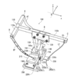
ここで、図2は、本実施形態における追尾装置500を構成する追尾子100の構造を具体的に示している。
図2に示すように、追尾子100は、太陽電池パネル10を上面に搭載する例えばT字状の保持部材110(110a部分と110b部分とからなる)と、保持部材110に連結する追尾機構とを備えている。追尾機構は、連結する保持部材110上に太陽電池パネル10が搭載された状態で、上記図1に示した架台20に設置されて用いられる。
ここで、本実施形態では、追尾子100は、上記駆動装置450の制御された駆動量に基づいて、保持部材110における少なくとも3点を駆動することにより、太陽電池パネル10が予め設定された太陽軌道を追尾するように構成されている。図2に示す一例では、保持部材110の形状としてT字状のものを例として用いており、T字状の保持部材110における3点としての例えば3つの端部(第1の駆動点~第3の駆動点に対応する)のうちの互いに対抗する一対の端部としての第1の端部A及び第2の端部Bには、例えば図2に示すように、第1のリボンAT及び第2のリボンBTが例えばネジによってそれぞれ取り付けられており、残りの端部としての第3の端部Cには、ワイヤーCTが例えば開口部Chを介して取り付けられている。なお、ワイヤーCTには、図示していないが、例えばバネなどの弾性部材を介在させることが好ましい。このようにするのは、後述するように、第1のリボンAT及び第2のリボンBTに対するような精密制御がワイヤーCT部分には要求されず、第1のリボンAT及び第2のリボンBTの位置を必要なタイミングで元に戻すためにはバネが介在していると効果的であるからである。
そして、図4に示す駆動装置450は、第1のリボンAT及び第2のリボンBTの各々の巻き取りを行う例えばサーボモーターである第1のモーター450a及び第2のモーター450cと、上記ワイヤーを巻き取る例えばステッピングモーターである第3のモーター450bとを備えている。また、制御装置400は、第1のモーター450a、上記第2のモーター450c及び上記第3のモーター450bの各々の巻き取り量を制御する。なお、ここで、第3のモーター450bの代わりに、一定の荷重を付与する定荷重バネを設けることもでき、その場合は上記ワイヤーCTを設けることなく、定荷重バネの先端を第3の端部Cに取り付けるようにしてもよい。
このような構成により、本実施形態に係る追尾装置500を備えた太陽光発電装置は、太陽電池パネル10を搭載する追尾子100の各々を駆動装置450により駆動させることができる。すなわち、保持部材110における3点の位置を制御して駆動させる構造により、太陽電池パネルを正確に太陽軌道に追尾させることができる。このように、分散可動型であって、簡易な構造で、低コストで実現できる追尾装置500を備えた太陽光発電装置を実現することができる。
このようにすると、一つの制御装置400により、複数の追尾子100を介して複数の太陽電池パネル10を一元制御することができ、簡易な構造の追尾装置500を備えた太陽光発電装置を実現することができる。
なお、本実施形態では、保持部材110の形状がT字状である場合について説明したが、本発明は当形状に限定されるものではなく種々の形状であってもよく、太陽電池パネル10を搭載可能な部材であってそのうちの少なくとも3点の位置を制御して駆動できる構造であればよい。また、本実施形態のように、位置を制御して駆動する点は3点に限定されるものではなく、4点以上であってもよいし、それに応じて適切に上記リボン及びワイヤー等の数も増加させることができる。
また、ここで、追尾機構は、図2に示すように、上記保持部材110を支える支柱部150と、上記支柱部150を支える土台部210とを備えており、該土台部210が取り付け部200を介して上記架台20に設置される。なお、図上では、取り付け部200が追尾子100に対応して1組設けられているように示されているが、複数の追尾子100が連結して架台20上に設置されるように、取り付け部200は延伸された構造となっている。
支柱部10は、開口部を有する頭部130と、頭部130に連続する肩部140と、一体的に形成されている。また、保持部材110と支柱部150とは、頭部130内の開口部を通過するリング120が支柱部150の底部に接続するようにして、互いに連結している。このようにすると、保持部材110と支柱部150とが、頭部130の開口部を通過するリング120によって連結しているため、リング120を介して保持部材110の駆動が円滑に行われる。その結果、太陽電池パネル10をより正確に太陽軌道に追尾させることができる。
また、土台部210内には、上記第1のリボンAT及び第2のリボンBTをそれぞれ通す第1のガイド190a及び第2のガイド190bを備えており、ワイヤーCTを通す開口部を有する突き出し部230をさらに備えている、このようにすると、第1のリボンAT及び第2のリボンBTが第1のガイド190a及び第2のガイド190bを通じて正確に巻き取られることが可能となる。さらに、ワイヤーCTが突き出し部230の開口部230Cを通じて正確に巻き取られることが可能となる。ここで、これらの第1のリボンAT、第2のリボンBT及びワイヤーCTは、例えば図4の第1の牽引点320a、第2の牽引点330a及び第3の牽引点340aのそれぞれに接続されており、制御装置400によって制御された駆動装置450の駆動量で駆動される。
また、本実施形態に係る太陽光発電装置において、支柱部150には、支持部材110の駆動量を制限する一対の肩部140が設けられている。上記の通り、支持部材110は、第1のリボンAT、第2のリボンBT及びワイヤーCTが制御された駆動量で巻き取られることで、太陽電池パネル10が予め設定された太陽軌道を追尾するものであるが、当該肩部140は、例えば一対の端部である第1の端部A及び第2の端部Bのいずれか一方が、駆動量に応じて、支持部材110を連結するリング120が頭部130の開口部内を一対の端部の移動方向に沿って移動することで、支持部材110全体が倒れてしまうことを止める役割を有する。したがって、肩部140は、支柱部150から頭部130に向かう上下方向(と定義する)と垂直な左右方向(と定義する)に突き出すような形状を有している。なお、突き出すような形状の左右方向における上下方向に対する角度は、例えば垂直な形状であるほか、支持部材110が倒れることを防止できるような角度で突き出すような形状であればよく、特に限定されるものではない。
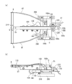
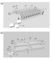
また、図2に示すように、追尾子100には、支柱部150の下部を例えば3方向から覆うように保持する壁部155がさらに形成されている。一方、土台部210には、支柱部150が収納可能な溝部210hが設けられており、支柱部150は、追尾子100が太陽光発電装置としての使用時において、壁部155から支柱部150を貫通孔220を介して貫通する貫通部材220t(例えばネジ)が挿入されていることで、直立状態を保持することを可能とする。一方で、追尾子100が太陽光発電装置としての例えば組立前の搬送時において、上記貫通部材220tを取り外して、例えば図3(a)の上方向から見た図及び図3(b)の横方向から見た図に示すように、壁部155の底部の一対の支え部170rが支柱部150の底部の回動構造160sを挟み込む構造を通じて、傾倒させることで、溝部210hに収納させることを可能とする。
このようにすると、複数の追尾子100の搬送時において、支柱部150が溝部210hに収納されることにより、追尾子100全体が折り畳まれたようなコンパクトな形態になるため、搬送時の可搬性に非常に優れていると共に、設置時の利便性にも非常に優れている。
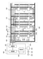
次に、図4を参照しながら、本実施形態に係る太陽光発電装置の駆動制御を実現するための配線・伝達軸構造について説明する。
図2及び図3で説明した構造を有する追尾子100の各々が、各太陽電池パネル10を支持するように、アレイ状に配置されている(図4では太陽電池パネル10が例えば8個示されているが、これは説明の便宜上であって、その数及びそれを搭載する追尾子の数はこれに限定されるものではない)。
また、図4に示すように、上記複数の追尾子100を備える追尾装置500には、複数の太陽電池パネル10を駆動する駆動装置450が接続されており、該駆動装置450には、複数の太陽電池パネル10が予め設定された太陽軌道を追尾するように駆動装置450の駆動量を制御する制御装置400が接続されている。
駆動装置450は、第1~第3の駆動装置450a~450cを含んでいる。第1の駆動装置450aは、例えばサーボモーターであり、第1の駆動軸320と連結しており、追尾子100の支持部材110における第1の端部Aに取り付けられた第1のリボンATを、第1の牽引点320aにて、巻き取ることを可能にする。
また、第2の駆動装置450bは、例えばサーボモーターであり、第2の駆動軸330と連結しており、追尾子100の支持部材110における第2の端部Bに取り付けられた第2のリボンBTを、第2の牽引点330aにて、巻き取ることを可能にする。
また、第3の駆動装置450cは、例えばステッピングモーターであり、追尾子100の支持部材110における第3の端部Cに取り付けられたワイヤーCTを、第3の駆動軸340を介して、第3の牽引点340aにて、巻き取ることを可能にする。
次に、制御装置400は、演算部410と処理部420と記憶部430とを備えている。制御装置400では、複数の太陽電池パネル10が予め設定された太陽軌道を追尾するように、太陽電池パネル10に関する追尾情報として、例えば太陽電池パネル10の設置位置の緯度、経度、高度情報や、日時情報などから計算された情報を記憶部430で保存しておく。そして、演算部410において、支持部材110の空間座標位置(例えば第1の端部A、第2の端部B及び第3の端部Cの空間座標位置を基点Dの位置から定める)と記憶部430から取り出した追尾情報とから、第1のリボンAT、第2のリボンBT及びワイヤーCTの巻き取り長さを計算し、処理部420を通じて、駆動装置450に指示する。なお、演算部410での巻き取り長さの計算では、支持部材110の空間座標位置の把握や各種の追尾情報、用いる各リボンやワイヤーの長さや厚みなどの情報の把握、それらに基づいた駆動装置450に支持する駆動量の計算は公知の技術で実現できるものである。
このようにして、複数の太陽電池パネル10が予め設定された太陽軌道を追尾する本実施形態の追尾装置500では、複数の太陽電池パネル10から取得される電力は電気線350、360を通じて、パワーコンディショナ510に送られて、そこで、直流電力を交流電力に変換し、トランス520に送電される。トランス520は、パワーコンディショナ510で変換された交流電力を負荷である電力系統1に送電する。なお、パワーコンディショナ510は、図示しない、コンバータ部と、インバータ部及び電圧制御部を有している。コンバータ部は、複数の追尾子100から出力された直流電圧を昇圧する昇圧回路を構成している。また、コンバータ部には、各追尾子100に対する動作指示情報に応じた出力電圧のデータが蓄積される。インバータ部は、コンバータ部から出力された直流電力を交流電力に変換するインバータ回路を構成している。電圧制御部は、MPPT(maximum power point tracing control)制御を行うものである。なお、MPPT制御は、山のぼり法ともいわれ、電圧制御部は、各追尾子100の出力電力(動作点)が最大電力点に近づくように、各追尾子の出力電圧を調整するものである。
さらに、本実施形態に係る太陽光発電装置において、太陽電池パネル10からの電気を取得する電気線350、360が複数の追尾子100に連続して接続され、また、影制御部310が信号線を通じて、複数の追尾子100のうち縦方向に配置された追尾子100の各々に連続して接続されている。影制御部310は、太陽電池パネル10にかかる影部分を考慮して、追尾子100に対する電気線350、360の電気的な接続を電力線切替部370にて制御する。影制御部310は、制御部400が、記憶部430に保存している上記追尾情報から計算された太陽光電池パネル10に影部分の情報に基づいて、処理部420を介して、影制御部310に指示を行う。このようにすると、複数の太陽電池パネル10のうち、影になっている太陽電池パネル10と影になっていない太陽電池パネル10とを二つの電気線によって適切に制御することにより、影になっている太陽電池パネルの発電電流量に全体が律速されることによる影響を回避することができる。例えば、上記MPPT制御による電圧制御で、太陽光電池パネルの並列制御や、電圧電流ともに制御し直列制御する配線構造に電力線切替部370にて適切に切り替えることが可能になり、高集光の太陽光発電装置を実現できる。なお、ここでは、2本の電気線350、360を設けて太陽電池パネル10の影部分による影響を制御する場合について説明したが、太陽電池パネル10に生じる影の程度で電流量は何段階にもなることから、3本以上の電気線を設けて段階的に制御して性能を向上させることができる。
また、上述した本実施形態に係る追尾子100の各々において、太陽電池パネル10を搭載する支持部材110の上面に、太陽電池パネル10を支える放熱板(図示せず)を設けるようにしてもよい。ここで、放熱板は、アルミ、銅などの熱伝導性の長い金属を用いて、太陽電池パネルと熱的に結合させ、太陽電池パネル10において上昇しやすい温度を放熱構造により抑制することができる。
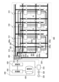
また、上述した本実施形態に係る追尾子100では、支持部材110における第3の端部Cに取り付けられたワイヤーCTを、第3の駆動軸340を介して、第3の牽引点340aにて、巻き取る構成例について説明したが、ワイヤーCTの代わりに、第1の端部Aに取り付けられた第1のリボンAT及び第2の端部Bに取り付けられた第2のリボンBTと同様に、リボンを用いることもできる。この場合、同様に、第3の駆動装置450cは、例えばサーボモーターを用いることができる。例えば図5に示すように、第3の駆動装置450cは、第3の駆動軸340と連結しており、該第3の駆動軸340を横方向に回転させることで、追尾子100の支持部材110における第3の端部Cに取り付けられたリボンを、第3の牽引点340aにて、巻き取ることを可能にする。
また、本実施形態に係る太陽光発電装置は、図6に示すように、架台20の全体を覆う透明部材からなるカバー550を設けるようにすることができる。ここで、具体的には、架台20の上に、その全体を覆うように透明部材からなるカバー550が設けられている。そして、カバー550は、例えば図示する南側に位置する端部において、傾斜面500aが形成されるように突き出し部500bを有している。このように適切な面で傾斜面500aが形成されているため、耐風性に優れた太陽光発電装置を実現できる。また、この場合、傾斜面500aの下側に、通常の追尾ではない太陽電池パネルを設置し、MPPT制御によって所定の電圧に昇圧し、他の太陽電池パネルと並列に接続する、又は、電流を制御し直列に接続することも可能である。
また、次述する図7に示すように、本実施形態に係る太陽光発電装置において、追尾装置500が複数連結される構造の場合でも同様に、耐風性を向上させるために傾斜面を適切な面に設けるとよい。例えば、南北報告及び東西方向の三行三列にアレイ状に配置された9つの追尾装置500が連結された構造において、西側から東側へ且つ北側から南側へ位置する順に第1~第9の追尾装置500が配置されているとすると、第1の追尾装置500は北面と西面に傾斜面、第2の追尾装置500は北面に傾斜面、第3の追尾装置500は北面と東面に傾斜面、第4の追尾装置500は西面に傾斜面、第5の追尾装置500は傾斜面なし、第6の追尾装置500は東面に傾斜面、第7の追尾装置500は南面と西面に傾斜面、第8の追尾装置500は南面に傾斜面、第9の追尾装置500は南面と東面に傾斜面を設けるとよい。
また、図7は、本発明の一実施形態に係る追尾装置500を複数備えた太陽光発電装置の構成例を示している。
図7に示す太陽光発電装置では、外部から上述した駆動装置450a~450cの各々に接続する駆動軸の接続部分において、軸を分割して例えばベルトとプーリーで接続部分を構成することにより、駆動装置450a~450cによる駆動力を正確に伝達可能とし、太陽光発電装置において生じ得る多少の高さバラツキや位置のズレによる影響を回避することも可能である。
また、図8(a)及び(b)は、本発明の一実施形態に係る追尾装置500を備えた太陽光発電装置の構成を立体的に表した例であり、(a)は例えば上記図5に示した一の追尾装置500を備える太陽光発電装置の構成例に駆動装置450や駆動軸450a~450cを加えた例を立体的に表しており、(b)は例えば上記図6に示した複数の追尾装置500を備える太陽光発電装置の構成例を立体的に表している。例えばこのような構成により、本実施形態に係る太陽光発電装置の実施が可能になる。なお、図8(a)及び(b)に示した各構成部分は上述で説明した通りであってその説明は繰り返さない。
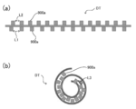
また、以上において、本実施形態に係る追尾装置500を構成する追尾子10は、第1のリボンAT及び第2のリボンBTを用いる場合について説明し、ワイヤーCTの代わりにリボンを用いることができることについて説明した。これらの場合において、例えば図9(a)及び(b)に示すように、リボンとして、両刃付きリボンDTを用いることもできる。具体的には、両刃付きリボンDTは、図9(a)に示すように、図中上下両側の面に複数の歯900aが設けられており、両刃付きリボンDTが巻き取られた際の外側(図では下側に相当する)における複数の歯の間隔L1は、両刃付きリボンDTが巻き取られた際の内側(図では上側に相当する)における複数の歯の間隔L2よりも大きい。さらに、図9(b)に示すように、両刃付きリボンが巻き取られた際の外側における複数の歯の間隔L3(隣り合う歯の上面間の距離)は、両刃付きリボンが巻き取られる前の直線上状態(図9(a)の状態)の内側(図では上側)における複数の歯の間隔L2と等しい。このようにすると、リボンの滑りによる撓みをより抑制することができる。
以上、本実施形態に係る太陽光発電装置について説明したが、本発明は当実施形態に限定されるものではなく、発明の範囲内で種々の形態が実施可能である。
本発明は太陽光発電装置に適用される分散型の太陽光追尾装置にとって有用である。
100 追尾子
10 太陽電池パネル
20 架台
30 支柱
40 基台
110(110a、110b) 支持部材
120 リング
130 頭部
140 肩部
150 支柱部
A 第1の端部
B 第2の端部
C 第3の端部
D 基点
AT 第1のリボン
BT 第2のリボン
CT ワイヤー
DT 両刃付きリボン
Ch 開口部
155 壁部
160s 支柱部の底部の回動構造
170r 壁部の底部
190a、190b 第1のガイド、第2のガイド
200 取り付け部
210 土台部
210h 溝部
220 貫通孔
220t 貫通部材
230 突き出し部
310 影制御部
320a 第1の牽引点
330a 第2の牽引点
340a 第3の牽引点
370 電力線切替部
400 制御部
410 演算部
420 処理部
430 記憶部
450 駆動部
500 追尾装置
510 パワーコンディショナ
520 トランス
530 電力系統
550 カバー
900a 歯
Claims (13)
- アレイ状に配置され、太陽光を電力に変換する複数の太陽電池パネルと、
前記複数の太陽電池パネルを駆動する駆動装置と、
前記複数の太陽電池パネルが予め設定された太陽軌道を追尾するように前記駆動装置の駆動量を制御する制御装置と、
追尾装置とを含む太陽光発電装置であって、
前記追尾装置は、
前記複数の太陽電池パネルの各々を搭載する複数の追尾子を備え、
前記複数の追尾子の各々は、
前記太陽電池パネルを搭載する保持部材と、
前記保持部材に連結する追尾機構とを備え、
前記駆動装置の前記制御された駆動量に基づいて、前記保持部材における少なくとも3点を駆動することにより、前記太陽電池パネルが予め設定された太陽軌道を追尾する、
ことを特徴とする太陽光発電装置。 - 請求項1に記載の太陽光発電装置において、
前記駆動装置は、前記保持部材の前記少なくとも3点をそれぞれ駆動する少なくとも3つの駆動部よりなる、
事を特徴とする太陽光発電装置。 - 請求項2に記載の太陽光発電装置において、
前記追尾子の各々は、
前記保持部材における前記3点のうちの少なくとも第1の駆動点及び第2の駆動点には、第1のリボン及び第2のリボンがそれぞれ取り付けられており、
前記駆動装置において、
前記第1の駆動部は、前記第1のリボンの巻き取りを行う第1のモーターよりなり、
前記第2の駆動部は、前記第2のリボンの巻き取りを行う第2のモーターよりなり、
前記第3の駆動部は、前記3点のうちの残りの第3の駆動点に荷重を付与する荷重付与部材よりなり、
前記制御装置は、
前記第1のモーター、前記第2のモーターの各々の巻き取り量を制御すると共に、前記荷重付与部材が付与する荷重を制御する、
ことを特徴とする太陽光発電装置。 - 請求項3に記載の太陽光発電装置において、
前記第3の駆動点には、前記荷重付与部材として、ワイヤ、バネを介在させたワイヤ、又は定荷重バネが取り付けられている、
ことを特徴とする太陽光発電装置。 - 請求項3に記載の太陽光発電装置において、
前記第3の駆動点には、前記荷重付与部材の代わりに、第3のリボンが取り付けられている、
ことを特徴とする太陽光発電装置。 - 請求項5に記載の太陽光発電装置において、
前記第1のリボン、前記第2のリボン及び前記第3のリボンとして、選択的に、両側の面に複数の歯を設けた両刃付きリボンが用いられ、
前記両刃付きリボンが巻き取られた際の外側における前記複数の歯の間隔は、前記両刃付きリボンが巻き取られる前の直線上状態の内側における前記複数の歯の間隔と等しい、
ことを特徴とする太陽光発電装置。 - 請求項1~6のうちのいずれか1項に記載の太陽光発電装置において、
前記追尾機構は、
前記保持部材を支える支柱部と、
前記支柱部を支える土台部とを備え、
前記保持部材と前記支柱部とを連結するリングがさらに設けられている、
ことを特徴とする太陽光発電装置。 - 請求項7に記載の太陽光発電装置において、
前記追尾機構は、
前記土台部内に、前記第1のリボン及び前記第2のリボンをそれぞれ通す第1のガイド及び第2のガイドを備えている、
ことを特徴とする太陽光発電装置。 - 請求項7又は8に記載の太陽光発電装置において、
前記支柱部には、前記支持部材の駆動量を制限する一対の肩部が設けられている、
ことを特徴とする太陽光発電装置。 - 請求項7~9のうちのいずれか1項に記載の太陽光発電装置において、
前記追尾機構は、
前記支柱部の下部を覆うように保持する壁部をさらに備えており、
前記土台部には、前記支柱部が収納可能な溝部が設けられており、
前記支柱部は、
前記追尾子の使用時において、前記壁部から前記支柱部を貫通する貫通部材によって直立している一方で、前記追尾子の搬送時において、前記貫通部材を取り外して傾倒することで前記溝部に収納される、
ことを特徴とする太陽光発電装置。 - 請求項7~10のうちのいずれか1項に記載の太陽光発電装置において、
前記複数の追尾子に連続して接続され、前記太陽電池パネルからの電気を取得する少なくとも第1の電気線及び第2の電気線と、
前記複数の追尾子のうち垂直に交差する二つの方向のうちの一の方向に配置された追尾子の各々に連続して接続された信号線を介して、前記太陽電池パネルにかかる影部分を考慮して、前記追尾子に対する前記第1の電気線及び前記第2の電気線の電気的な接続を制御する影制御部と、をさらに備えている、
ことを特徴とする太陽光発電装置。 - 請求項1~11のうちのいずれか1項に記載の太陽光発電装置において、
前記追尾装置を搭載する架台と、
前記架台の上に、前記追尾装置の全体を覆うように設けられた透明部材からなる矩形状のケースと、をさらに備えており、
前記ケースの少なくとも一面が傾斜している、
ことを特徴とする太陽光発電装置。 - 請求項1~12のうちのいずれか1項に記載の太陽光発電装置において、
互いに連結した前記追尾装置を複数備え、
一の前記制御装置は、前記駆動装置を介して、前記複数の追尾装置を駆動する、
ことを特徴とする太陽光発電装置。
Priority Applications (1)
| Application Number | Priority Date | Filing Date | Title |
|---|---|---|---|
| JP2017530850A JPWO2017018367A1 (ja) | 2015-07-28 | 2016-07-25 | 太陽光発電装置 |
Applications Claiming Priority (2)
| Application Number | Priority Date | Filing Date | Title |
|---|---|---|---|
| JP2015-148510 | 2015-07-28 | ||
| JP2015148510 | 2015-07-28 |
Publications (1)
| Publication Number | Publication Date |
|---|---|
| WO2017018367A1 true WO2017018367A1 (ja) | 2017-02-02 |
Family
ID=57884722
Family Applications (1)
| Application Number | Title | Priority Date | Filing Date |
|---|---|---|---|
| PCT/JP2016/071677 Ceased WO2017018367A1 (ja) | 2015-07-28 | 2016-07-25 | 太陽光発電装置 |
Country Status (2)
| Country | Link |
|---|---|
| JP (1) | JPWO2017018367A1 (ja) |
| WO (1) | WO2017018367A1 (ja) |
Citations (8)
| Publication number | Priority date | Publication date | Assignee | Title |
|---|---|---|---|---|
| US20110000543A1 (en) * | 2009-07-02 | 2011-01-06 | Errico Joseph P | Solar energy collection and conversion system |
| JP2011091450A (ja) * | 2011-02-07 | 2011-05-06 | Nikkeikin Aluminium Core Technology Co Ltd | 太陽電池パネル |
| JP2013089844A (ja) * | 2011-10-20 | 2013-05-13 | Panasonic Corp | 追尾型太陽電池装置 |
| JP2013110252A (ja) * | 2011-11-21 | 2013-06-06 | Etsuya Shinagawa | 自動太陽追尾装置付太陽エネルギー収集システム |
| JP2013529849A (ja) * | 2010-06-29 | 2013-07-22 | スマート フラワー エナジー テクノロジー ゲゼルシャフト ミット ベシュレンクテル ハフツング | 折り畳み式のソーラーモジュール |
| JP2014505374A (ja) * | 2011-02-10 | 2014-02-27 | エタネジー リミテッド | 位置決めシステム |
| JP2015095146A (ja) * | 2013-11-13 | 2015-05-18 | 伸和工業株式会社 | 太陽光発電システム |
| JP2015518703A (ja) * | 2012-04-26 | 2015-07-02 | ジュ リ,ソン | 太陽光発電用追跡装置 |
-
2016
- 2016-07-25 WO PCT/JP2016/071677 patent/WO2017018367A1/ja not_active Ceased
- 2016-07-25 JP JP2017530850A patent/JPWO2017018367A1/ja active Pending
Patent Citations (8)
| Publication number | Priority date | Publication date | Assignee | Title |
|---|---|---|---|---|
| US20110000543A1 (en) * | 2009-07-02 | 2011-01-06 | Errico Joseph P | Solar energy collection and conversion system |
| JP2013529849A (ja) * | 2010-06-29 | 2013-07-22 | スマート フラワー エナジー テクノロジー ゲゼルシャフト ミット ベシュレンクテル ハフツング | 折り畳み式のソーラーモジュール |
| JP2011091450A (ja) * | 2011-02-07 | 2011-05-06 | Nikkeikin Aluminium Core Technology Co Ltd | 太陽電池パネル |
| JP2014505374A (ja) * | 2011-02-10 | 2014-02-27 | エタネジー リミテッド | 位置決めシステム |
| JP2013089844A (ja) * | 2011-10-20 | 2013-05-13 | Panasonic Corp | 追尾型太陽電池装置 |
| JP2013110252A (ja) * | 2011-11-21 | 2013-06-06 | Etsuya Shinagawa | 自動太陽追尾装置付太陽エネルギー収集システム |
| JP2015518703A (ja) * | 2012-04-26 | 2015-07-02 | ジュ リ,ソン | 太陽光発電用追跡装置 |
| JP2015095146A (ja) * | 2013-11-13 | 2015-05-18 | 伸和工業株式会社 | 太陽光発電システム |
Also Published As
| Publication number | Publication date |
|---|---|
| JPWO2017018367A1 (ja) | 2018-05-17 |
Similar Documents
| Publication | Publication Date | Title |
|---|---|---|
| Fathabadi | Novel high efficient offline sensorless dual-axis solar tracker for using in photovoltaic systems and solar concentrators | |
| Seme et al. | Dual-axis photovoltaic tracking system–Design and experimental investigation | |
| EP2543879B1 (en) | Solar generator apparatus with cable-controlled tracking | |
| US9455665B1 (en) | Solar tracker cleaning system and method | |
| KR100998337B1 (ko) | 수상 태양광 발전장치 | |
| JP4955194B2 (ja) | 太陽光発電システム | |
| KR101184425B1 (ko) | 태양광 발전용 추적장치 | |
| KR100864215B1 (ko) | 다수의 크랭크축을 이용한 태양광 발전장치 | |
| US10680127B2 (en) | Power generation circuit unit | |
| JP2016092969A (ja) | 角度可変形太陽光発電システム | |
| JP5617061B2 (ja) | 太陽光発電パネルユニット及び太陽光発電装置 | |
| KR20140028179A (ko) | 태양추적 발전이 가능한 빌딩 회전형 태양광 발전소 | |
| IT7949466A0 (it) | Apparecchio collettore di energia solare per la trasformazione in calore in un liquido | |
| JP2016103952A (ja) | 太陽光発電装置 | |
| JP2016183800A (ja) | 太陽光集光システムおよびヘリオスタット | |
| JP2018074832A (ja) | 太陽光発電装置 | |
| JPWO2017018367A1 (ja) | 太陽光発電装置 | |
| KR20190000481A (ko) | 태양광 발전장치 | |
| KR20100022540A (ko) | 태양전지판의 각도조절장치 | |
| KR20200004066A (ko) | 태양광발전모듈을 구비한 스마트 팜 | |
| KR20140005878U (ko) | 태양광 경사 가변형 구조물 | |
| US9732987B2 (en) | Two axis solar tracking system | |
| CN115247627B (zh) | 一种基于虚拟电厂的分布式电能调节装置 | |
| KR102151850B1 (ko) | 모듈화된 태양광 추적 장치 | |
| WO2018079677A1 (ja) | 集光型太陽光発電装置 |
Legal Events
| Date | Code | Title | Description |
|---|---|---|---|
| 121 | Ep: the epo has been informed by wipo that ep was designated in this application |
Ref document number: 16830472 Country of ref document: EP Kind code of ref document: A1 |
|
| ENP | Entry into the national phase |
Ref document number: 2017530850 Country of ref document: JP Kind code of ref document: A |
|
| NENP | Non-entry into the national phase |
Ref country code: DE |
|
| 122 | Ep: pct application non-entry in european phase |
Ref document number: 16830472 Country of ref document: EP Kind code of ref document: A1 |