WO2017018396A1 - Dispositif de communication et procédé de communication - Google Patents
Dispositif de communication et procédé de communication Download PDFInfo
- Publication number
- WO2017018396A1 WO2017018396A1 PCT/JP2016/071787 JP2016071787W WO2017018396A1 WO 2017018396 A1 WO2017018396 A1 WO 2017018396A1 JP 2016071787 W JP2016071787 W JP 2016071787W WO 2017018396 A1 WO2017018396 A1 WO 2017018396A1
- Authority
- WO
- WIPO (PCT)
- Prior art keywords
- message
- management server
- communication
- report
- power
- Prior art date
- Legal status (The legal status is an assumption and is not a legal conclusion. Google has not performed a legal analysis and makes no representation as to the accuracy of the status listed.)
- Ceased
Links
Images




Classifications
-
- H—ELECTRICITY
- H02—GENERATION; CONVERSION OR DISTRIBUTION OF ELECTRIC POWER
- H02J—ELECTRIC POWER NETWORKS; CIRCUIT ARRANGEMENTS OR SYSTEMS FOR SUPPLYING OR DISTRIBUTING ELECTRIC POWER; SYSTEMS FOR STORING ELECTRIC ENERGY
- H02J3/00—Circuit arrangements for AC mains or AC distribution networks
- H02J3/38—Arrangements for feeding a single network from two or more generators or sources in parallel; Arrangements for feeding already energised networks from additional generators or sources in parallel
-
- H—ELECTRICITY
- H02—GENERATION; CONVERSION OR DISTRIBUTION OF ELECTRIC POWER
- H02J—ELECTRIC POWER NETWORKS; CIRCUIT ARRANGEMENTS OR SYSTEMS FOR SUPPLYING OR DISTRIBUTING ELECTRIC POWER; SYSTEMS FOR STORING ELECTRIC ENERGY
- H02J13/00—Circuit arrangements for providing remote monitoring or remote control of equipment in a power distribution network
-
- H—ELECTRICITY
- H04—ELECTRIC COMMUNICATION TECHNIQUE
- H04Q—SELECTING
- H04Q9/00—Arrangements in telecontrol or telemetry systems for selectively calling a substation from a main station, in which substation desired apparatus is selected for applying a control signal thereto or for obtaining measured values therefrom
-
- Y—GENERAL TAGGING OF NEW TECHNOLOGICAL DEVELOPMENTS; GENERAL TAGGING OF CROSS-SECTIONAL TECHNOLOGIES SPANNING OVER SEVERAL SECTIONS OF THE IPC; TECHNICAL SUBJECTS COVERED BY FORMER USPC CROSS-REFERENCE ART COLLECTIONS [XRACs] AND DIGESTS
- Y02—TECHNOLOGIES OR APPLICATIONS FOR MITIGATION OR ADAPTATION AGAINST CLIMATE CHANGE
- Y02E—REDUCTION OF GREENHOUSE GAS [GHG] EMISSIONS, RELATED TO ENERGY GENERATION, TRANSMISSION OR DISTRIBUTION
- Y02E40/00—Technologies for an efficient electrical power generation, transmission or distribution
- Y02E40/70—Smart grids as climate change mitigation technology in the energy generation sector
-
- Y—GENERAL TAGGING OF NEW TECHNOLOGICAL DEVELOPMENTS; GENERAL TAGGING OF CROSS-SECTIONAL TECHNOLOGIES SPANNING OVER SEVERAL SECTIONS OF THE IPC; TECHNICAL SUBJECTS COVERED BY FORMER USPC CROSS-REFERENCE ART COLLECTIONS [XRACs] AND DIGESTS
- Y04—INFORMATION OR COMMUNICATION TECHNOLOGIES HAVING AN IMPACT ON OTHER TECHNOLOGY AREAS
- Y04S—SYSTEMS INTEGRATING TECHNOLOGIES RELATED TO POWER NETWORK OPERATION, COMMUNICATION OR INFORMATION TECHNOLOGIES FOR IMPROVING THE ELECTRICAL POWER GENERATION, TRANSMISSION, DISTRIBUTION, MANAGEMENT OR USAGE, i.e. SMART GRIDS
- Y04S10/00—Systems supporting electrical power generation, transmission or distribution
- Y04S10/12—Monitoring or controlling equipment for energy generation units, e.g. distributed energy generation [DER] or load-side generation
- Y04S10/123—Monitoring or controlling equipment for energy generation units, e.g. distributed energy generation [DER] or load-side generation the energy generation units being or involving renewable energy sources
Definitions
- the present invention relates to a communication device and a communication method for receiving a power command message.
- Electric power including a power flow suppression message (for example, DR: Demand Response) requesting suppression of power flow from the power system to the facility or a power flow suppression message requesting suppression of reverse power flow from the facility to the power system Command message is known.
- a power command message is transmitted from a management server belonging to a power company or a power distribution company to a facility via a communication line (for example, Patent Document 1).
- the communication device includes a receiving unit that receives a power command message from a management server via a communication line, and a transmission unit that transmits a predetermined message having a predetermined format to the management server.
- the transmitting unit transmits a message selected from the predetermined messages as the confirmation message for confirming the communication state of the communication line.
- the management server transmits a power command message to the communication device via a communication line, and the communication device transmits a predetermined message having a predetermined format to the management server.
- the step B includes a step of transmitting a message selected from the predetermined messages as the confirmation message for confirming the communication state of the communication line.
- FIG. 1 is a diagram illustrating a power management system 1 according to the embodiment.
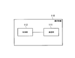
- FIG. 2 is a diagram illustrating the communication device 110 according to the embodiment.
- FIG. 3 is a diagram illustrating the lower management server 300 according to the embodiment.
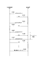
- FIG. 4 is a diagram illustrating a communication method according to the embodiment.
- FIG. 5 is a diagram illustrating a communication method according to another embodiment 1.
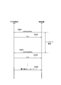
- FIG. 6 is a diagram illustrating a communication method according to another embodiment 2.
- FIG. 7 is a diagram illustrating a communication method according to another embodiment 3.
- FIG. 8 is a diagram illustrating a communication method according to another embodiment 3.
- the communication state of the communication line between the management server and the facility is one of the elements as to whether the tidal flow or the reverse tidal flow is appropriately suppressed according to the power command message. . Therefore, in order to appropriately respond to the power command message, it is necessary to confirm the communication state of the communication line in advance.
- a communication apparatus includes a receiving unit that receives a power command message from a management server via a communication line, and a transmission unit that transmits a predetermined message having a predetermined format to the management server, A message selected from the predetermined messages is transmitted to the management server as a confirmation message for confirming the communication state of the communication line.
- the communication device transmits a message selected from the predetermined messages to the management server as a confirmation message for confirming the communication state of the communication line.
- the power command message can be transmitted based on the communication state of the network 200 (communication line) within the framework of the standard that defines the predetermined message. Tidal flow or reverse tide flow can be controlled.
- FIG. 1 is a diagram illustrating a power management system 1 according to the embodiment.
- the power management system 1 includes a customer facility 100 (hereinafter simply referred to as a facility 100), a network 200, a lower-level management server 300, and a higher-level management server 400.
- the facility 100 includes a communication device 110, a load 120, and a distributed power source 130.
- the communication device 110 is a communication device provided in the facility 100 and communicates with the lower management server 300 or the upper management server 400.
- the communication device 110 is a device (Energy Management System) that manages the power of equipment provided in the facility 100 or a PCS (Power Conditioning System) that controls the distributed power supply 130.
- the load 120 is a device that consumes power.
- the load 120 includes devices such as a refrigerator, lighting, an air conditioner, and a television, for example.
- the load 120 may include a single device or a plurality of devices.
- the distributed power supply 130 is a device that generates power.
- the distributed power supply 130 includes devices such as a solar cell, a fuel cell, and a storage battery, for example.
- the distributed power supply 130 may include a single device or a plurality of devices.
- the distributed power source 130 may include at least two of a solar cell, a fuel cell, and a storage battery. More specifically, the distributed power source 130 includes a solar cell and a storage battery, or includes a fuel cell and a storage battery.
- the facility 100A, the facility 100B, and the facility 100C are illustrated as the facility 100.
- the facility 100A, the facility 100B, and the facility 100C have the same configuration.
- the present invention is not limited to this, and there may be one facility 100 or a plurality of facilities 100.
- the network 200 may be any communication means for connecting the facility 100 and the lower management server 300.
- the network 200 is a communication line, for example, the Internet.
- the network 200 is provided by, for example, a provider with which each facility 100 contracts.
- the network 200 may be a dedicated line.
- the lower management server 300 is a server belonging to an aggregator such as a power distribution company.
- the aggregator is a business operator that manages the tide flow rate or the reverse tide flow rate of the facility 100 contracted with the aggregator.
- the lower management server 300A and the lower management server 300B are illustrated as the lower management server 300.
- the lower management server 300A and the lower management server 300B have the same configuration. There may be one lower management server 300 or a plurality of lower management servers 300.
- the lower management server 300 may be integrated with the upper management server 400.
- the upper management server 400 is a server belonging to an electric power company such as an electric power company.
- the electric power company may entrust the management of the tidal flow or reverse tidal flow of the facility 100 to the aggregator.
- the upper management server 400 transmits a power flow control message (for example, DR; Demand Response) that requests an increase or decrease in power flow (power supply amount) to the facility 100 from the power system.
- the upper management server 400 transmits a reverse flow control message requesting an increase or decrease in reverse flow from the facility 100 to the power system.
- the upper management server 400 may transmit a power control message for controlling the operation of the distributed power supply 130.
- the power supply control message is a command for controlling the operation of the distributed power supply 130 of the facility 100 as a virtual power plant, and examples thereof include commands such as charging, discharging, power generation, reverse power flow, and automatic operation.
- the power control message, the power flow control message, and the reverse power control message are collectively referred to as a power command message.
- the tidal current control message includes information indicating the control degree (suppression degree) of the amount of power (tidal flow rate) supplied from the power system to the facility 100.
- the degree of suppression may be represented by an absolute value of electric energy (for example, OO kW).
- the suppression degree may be represented by a relative value of the electric energy (for example, a decrease in OO kW).
- the suppression degree may be expressed as a power consumption suppression ratio (for example, OO%).
- the power flow control message may include information indicating a power purchase price that is the price of the power flow from the power system. By setting a high price as the power purchase price, it is expected that the amount of power supplied from the power system to the facility 100 will be suppressed.
- the reverse power flow control message includes information indicating the control degree (suppression degree) of the electric energy (reverse power flow rate) output from the facility 100 to the power system.
- the reverse power flow control message includes information indicating the degree of suppression of the output of the distributed power supply.
- the suppression degree may be represented by an absolute value (for example, OO kW) of the output of the distributed power source.
- the degree of suppression may be represented by a relative value of the output of the distributed power source (for example, a decrease in OO kW).
- the suppression degree may be expressed as a suppression ratio (for example, OO%) of the output of the distributed power source.
- the suppression ratio may be a ratio with respect to an output that is certified as an output capability of the PCS that controls the distributed power supply (hereinafter referred to as equipment certified output) when the distributed power supply is installed in the facility 100.
- equipment certified output an output that is certified as an output capability of the PCS that controls the distributed power supply
- the facility certified output is the smaller output capability of these output capabilities.
- the facility authorization output is the sum of the output capacities of the plurality of PCSs.
- the type of the distributed power source 130 in addition to the commands such as charging, discharging, power generation, reverse power flow or automatic operation as described above, the type of the distributed power source 130, the AC upper limit setting of charging or discharging, the AC lower limit setting of charging or discharging, charging Commands such as amount, charge time, AC effective capacity, discharge amount, discharge time, power generation amount, power generation time, reverse power flow rate, reverse power flow time or automatic operation time may be included.
- a format compliant with an automatic demand response can be used as a format of the power supply control message, the power flow control message, and the reverse power flow control message.
- Communication between the upper management server 400 and the lower management server 300 and communication between the lower management server 300 and the facility 100 may be performed by a method based on the same standard.
- a method conforming to the same standard for example, a method conforming to the Open ADR standard can be used. Any version of the Open ADR standard can be used. For example, Open ADR2.0 can be used.
- FIG. 2 is a diagram illustrating the communication device 110 according to the embodiment.
- the communication device 110 includes a communication unit 111 and a control unit 112.
- the communication unit 111 includes a communication module and the like, and communicates with the lower management server 300 or the upper management server 400.
- a case where the communication unit 111 communicates with the lower management server 300 is illustrated.
- the communication unit 111 receives a power command message including a power control message, a power flow control message, or a reverse power flow control message from the lower management server 300 via the network 200 (communication line).
- the communication unit 111 communicates with the lower-level management server 300 by a method compliant with the Open ADR standard.
- the communication unit 111 transmits a predetermined message having a predetermined format to the lower management server 300.
- the predetermined format is a format defined by the Open ADR standard.
- the communication unit 111 transmits a message selected from predetermined messages as a confirmation message for confirming the communication state of the network 200 (communication line).
- the confirmation of the communication state is started at an arbitrary timing. Specifically, the start timing may be started when the communication device 110 is first connected to the lower-level management server 300, or the communication state is not normally confirmed, and a predetermined event is sent.
- the confirmation of the communication state may be started as a trigger. Examples of the predetermined event include detection of a signal by a user operation, detection of a confirmation request signal from the lower management server 300, execution of power flow control or reverse power flow control.
- the communication state of the network 200 is to confirm whether or not normal communication is possible. Specifically, for example, it is possible to confirm whether or not an error has occurred in the communication line.
- the communication state of the network 200 is performed by checking whether or not an error has occurred in the communication line.
- a report message for example, oadrUpdateReport
- oadrUpdateReport for reporting the state of the distributed power supply 130 of the facility 100 is used as the confirmation message.
- the report message used as the confirmation message is transmitted in response to a report request message (for example, oadrCreateReport) received from the lower management server 300.
- the report message used as the confirmation message may be a message that does not include information indicating the state of the distributed power supply 130. That is, the report request message is a message that requests transmission of a message that does not include information indicating the state of the distributed power supply 130.
- the report message may be an empty message. An empty message is one that contains no other information besides the message format.
- the report message used as the confirmation message may be a message including information having the smallest data amount among the information indicating the state of the distributed power supply 130. That is, the report request message is a message for requesting transmission of a message including information having the smallest data amount (information indicating the state of the distributed power supply 130).
- the report request message includes information indicating a report interval for transmitting the report message.
- the communication unit 111 transmits a report message at a report interval indicated by the report request message.
- the reporting interval is a heartbeat period for confirming the communication state of the network 200 (communication line).
- the control unit 112 includes a CPU, a memory, and the like, and controls the communication unit 111. For example, the control unit 112 controls transmission of the report message in response to the report request message.
- FIG. 3 is a diagram illustrating the lower management server 300 according to the embodiment.
- the lower management server 300 includes a communication unit 310 and a control unit 320.
- the communication unit 310 includes a communication module and the like, and communicates with the facility 100 and the upper management server 400. For example, the communication unit 310 receives a power command message including a power control message, a power flow control message, or a reverse power flow control message from the upper management server 400.
- the communication unit 310 transmits a power command message including a power control message, a power flow control message, or a reverse power flow control message to the facility 100 via the network 200 (communication line). Since the management of the tidal flow or reverse tidal flow of the facility 100 is entrusted to the aggregator (lower management server 300), the content of the power command message transmitted to the facility 100 is the content of the power command message received from the higher management server 400. And may be different. More specifically, the power command message sent from the upper management server 400 may be achieved by each facility 100 or may be achieved by a plurality of facilities 100. If the power command message is to be achieved at a plurality of facilities 100, the lower management server 300 selects an appropriate facility 100. Then, the lower management server 300 transmits a power command message to be achieved in each facility 100 to the selected facility 100.
- the communication unit 310 communicates with the communication device 110 by a method compliant with the Open ADR standard.
- the predetermined format is a format defined by the Open ADR standard.
- the communication unit 310 transmits the above-described report request message to the communication device 110 and receives the above-described report message from the communication device 110.
- the control unit 320 includes a CPU and a memory, and controls the communication unit 310.
- control unit 320 determines the communication state of the network 200 (communication line) based on the report message (confirmation message) described above. Based on the communication state of the communication line, the control unit 320 determines the transmission partner (communication device 110) of the power command message and the content of the power command message (control amount of power flow or control amount of reverse power flow). Specifically, control unit 320 excludes communication device 110 in which an error has occurred in the communication line from the transmission partner of the power command message. The control unit 320 excludes the facility 100 having the communication device 110 in which an error has occurred in the communication line, and estimates an expected reduction amount that is a tidal flow rate or a reverse tidal flow rate that decreases according to the tidal flow control message.
- FIG. 4 is a diagram illustrating a communication method according to the embodiment.
- step S ⁇ b> 101 the communication device 110 transmits a registration request message (for example, oadrRegisterReport) requesting registration of information that can be reported by the communication device 110 to the lower management server 300.
- a registration request message for example, oadrRegisterReport
- step S ⁇ b> 102 the lower management server 300 transmits a response message (Ack) to the registration request message to the communication device 110.
- step S103 the lower-level management server 300 transmits a report request message (for example, oadrCreateReport) to the communication device 110.
- step S ⁇ b> 104 the communication apparatus 110 transmits a response message (Ack) to the report request message to the lower management server 300.
- the report request message includes information indicating a report interval for transmitting the report message.
- step S105 and step S107 the communication apparatus 110 transmits a report message at a report interval indicated by the report request message.
- step S106 and step S108 the lower management server 300 transmits a response message (Ack) to the report message to the communication device 110.
- the transmission interval (report interval) of the report message is a heartbeat period for confirming the communication state of the network 200 (communication line).
- the lower management server 300 determines that an error has occurred in the communication line when, for example, the report message is not received even after the report interval has passed.
- the lower management server 300 may determine that an error has occurred in the communication line even when a report message is received after the reporting interval.
- step S109 when there is no error in the network 200 (communication line), the lower management server 300 transmits a power command message including a power control message, a power flow control message, or a reverse power flow control message to the communication device 110.
- the communication device 110 transmits a message selected from predetermined messages to the lower management server 300 as a confirmation message for confirming the communication state of the communication line.
- the power command message can be transmitted based on the communication state of the network 200 (communication line) within the framework of a standard (for example, Open ADR) that defines a predetermined message.
- the tidal flow or reverse tidal flow can be appropriately controlled by sending a message.
- the lower-level management server 300 belongs to the aggregator entrusted by the power company to manage the tidal flow or the reverse tidal flow of the facility 100.
- the aggregator Can be entrusted to the contractor.
- the report request message includes information indicating a report interval for transmitting the report message, and the report message is transmitted a plurality of times according to the report interval in response to the transmission of one report request message.
- one report message is transmitted in response to one report request message.
- the report request message includes a minimum time as a reply time for returning the report message in response to the report request message.
- the minimum time for example, it can be set to zero, set to a predetermined second (for example, 2 seconds) or less, or set to several microseconds. That is, the communication unit 111 of the communication device 110 transmits the report message according to the reply time in response to the report request message. According to the other embodiment 1, for example, there is an effect that the communication state can be confirmed immediately.
- FIG. 5 is a diagram illustrating a communication method according to another embodiment 1.
- step S ⁇ b> 201 the communication device 110 transmits a registration request message (for example, oadrRegisterReport) requesting registration of information that can be reported by the communication device 110 to the lower management server 300.
- step S ⁇ b> 202 the lower management server 300 transmits a response message (Ack) to the registration request message to the communication device 110.
- the lower-level management server 300 transmits a report request message (for example, oadrCreateReport) to the communication device 110.
- a report request message for example, oadrCreateReport
- the communication device 110 transmits a response message (Ack) to the report request message to the lower management server 300.
- the report request message includes a minimum time as a reply time for returning the report message in response to the report request message.
- step S205 and step S209 the communication device 110 transmits a report message according to the reply time indicated by the report request message.
- step S206 and step S210 the lower management server 300 transmits a response message (Ack) to the report message to the communication device 110.
- the transmission interval of the report message is a heartbeat period for confirming the communication state of the network 200 (communication line).
- step S211 the lower management server 300 transmits a power command message including a power control message, a power flow control message, or a reverse power flow control message to the communication device 110 when no error has occurred in the network 200 (communication line).
- the confirmation message for confirming the communication state of the network 200 is a report message transmitted in response to the report request message.
- the confirmation message is a response message to a registration request message (for example, oadrRegisterReport) requesting registration that there is no information to report to the lower management server 300.
- the registration request message is transmitted from the lower management server 300 to the communication device 110, and the response message to the registration request message is transmitted from the communication device 110 to the lower management server 300.
- the registration request message includes information that the communication device 110 recognizes as an error. As a result, it is possible to check the communication state of the network 200 (communication line) using a response message to the registration request message while reducing unnecessary operations for the communication device 110 using the registration request message.
- FIG. 6 is a diagram illustrating a communication method according to another embodiment 2.
- the lower management server 300 sends a registration request message (for example, oadrRegisterReport) requesting registration that there is no information to be reported to the lower management server 300 to the communication device 110. Send to.
- a registration request message for example, oadrRegisterReport
- step S302 and step 304 the communication apparatus 110 transmits a response message (Ack) to the registration request message to the lower management server 300.
- the transmission interval of the response message is a heartbeat period for confirming the communication state of the network 200 (communication line).
- the registration request message includes information that the communication device 110 recognizes as an error. Therefore, the communication device 110 does not need to perform an extra operation except for sending a response message.
- step S305 the subordinate management server 300 transmits a power command message including a power control message, a power flow control message, or a reverse power flow control message to the communication device 110 when no error has occurred in the network 200 (communication line).
- the communication device 110 transmits a confirmation message in response to a request from the lower management server 300.
- the communication device 110 autonomously transmits a confirmation message without depending on a request from the lower management server 300.
- the confirmation message is, for example, an inquiry message (for example, oadrPoll) for inquiring whether or not there is a request from the lower management server 300 to the communication device 110.
- FIG. 7 is a diagram illustrating a communication method according to another embodiment 3.
- the communication apparatus 110 transmits an inquiry message (for example, oadrPoll) for inquiring whether there is a request to the communication apparatus 110 from the lower management server 300.
- the transmission interval of the inquiry message is a heartbeat period for confirming the communication state of the network 200 (communication line).
- step S402 and step S407 the lower-level management server 300 transmits a transmission request message (for example, oaderCreateReport) requesting transmission of the registration request message to the communication apparatus 110.
- a transmission request message for example, oaderCreateReport
- the communication apparatus 110 transmits a response message (Ack) to the transmission request message to the lower management server 300.
- step S404 and step S409 the communication apparatus 110 transmits a registration request message (for example, oadrRegisterReport) requesting registration of information that can be reported by the communication apparatus 110 to the lower management server 300.
- a registration request message for example, oadrRegisterReport
- the lower management server 300 transmits a response message (Ack) to the registration request message to the communication device 110.
- step S411 when no error has occurred in the network 200 (communication line), the lower-level management server 300 transmits a power command message including a power control message, a power flow control message, or a reverse power flow control message to the communication device 110.
- the confirmation message includes information indicating whether or not the distributed power supply 130 is compatible with the power command message, information indicating that the distributed power supply 130 is a message used for the power command message, and confirmation. Contains the message transmission interval.
- the communication device 110 may transmit a confirmation message in response to a request from the lower management server 300, and autonomously transmits a confirmation message without depending on the request from the lower management server 300. Also good.
- FIG. 8 is a diagram illustrating a communication method according to another embodiment 4.
- step S501 and step S503 the communication device 110 transmits a confirmation message (for example, oadrHeartBeat) to the subordinate management server 300.
- step S502 and step S504 the lower management server 300 transmits a response message (Ack) to the confirmation message to the communication device 110.
- the transmission interval of the confirmation message is a heartbeat period for confirming the communication state of the network 200 (communication line).
- step S505 when no error has occurred in the network 200 (communication line), the lower management server 300 transmits a power command message including a power control message, a power flow control message, or a reverse power flow control message to the communication device 110.
- the communication between the upper management server 400 and the lower management server 300 and the communication between the lower management server 300 and the facility 100 are performed in a system conforming to the Open ADR standard.
- Communication between the lower management server 300 and the facility 100 may be based on a standard other than the Open ADR standard. Therefore, the predetermined message transmitted and received between the lower management server 300 and the facility 100 may have a predetermined format defined in a standard other than the Open ADR standard.
Landscapes
- Engineering & Computer Science (AREA)
- Power Engineering (AREA)
- Computer Networks & Wireless Communication (AREA)
- Remote Monitoring And Control Of Power-Distribution Networks (AREA)
Abstract
La présente invention concerne un dispositif de communication qui est pourvu d'une unité de réception qui reçoit un message de commande de puissance à partir d'un serveur de gestion par l'intermédiaire d'une ligne de communication; et d'une unité de transmission qui transmet, au serveur de gestion, des messages prédéterminés qui présentent des formats prédéterminés. L'unité de transmission transmet, au serveur de gestion, un message sélectionné parmi les messages prédéterminés sous forme de message de confirmation pour confirmer l'état de communication de la ligne de communication.
Applications Claiming Priority (2)
| Application Number | Priority Date | Filing Date | Title |
|---|---|---|---|
| JP2015-149998 | 2015-07-29 | ||
| JP2015149998 | 2015-07-29 |
Publications (1)
| Publication Number | Publication Date |
|---|---|
| WO2017018396A1 true WO2017018396A1 (fr) | 2017-02-02 |
Family
ID=57884428
Family Applications (1)
| Application Number | Title | Priority Date | Filing Date |
|---|---|---|---|
| PCT/JP2016/071787 Ceased WO2017018396A1 (fr) | 2015-07-29 | 2016-07-26 | Dispositif de communication et procédé de communication |
Country Status (1)
| Country | Link |
|---|---|
| WO (1) | WO2017018396A1 (fr) |
Cited By (2)
| Publication number | Priority date | Publication date | Assignee | Title |
|---|---|---|---|---|
| JP2023104762A (ja) * | 2022-01-18 | 2023-07-28 | 大阪瓦斯株式会社 | 表示システム |
| JP2023177798A (ja) * | 2022-06-03 | 2023-12-14 | 京セラ株式会社 | 管理装置及び管理方法 |
Citations (3)
| Publication number | Priority date | Publication date | Assignee | Title |
|---|---|---|---|---|
| JP2014204407A (ja) * | 2013-04-09 | 2014-10-27 | 京セラ株式会社 | 情報機器、制御装置、制御システム及び制御方法 |
| JP2014216862A (ja) * | 2013-04-25 | 2014-11-17 | 京セラ株式会社 | 制御システム、情報機器及び制御方法 |
| JP2015088894A (ja) * | 2013-10-30 | 2015-05-07 | 東芝ライテック株式会社 | 通信機器、通信中継機器、通信方法および通信システム |
-
2016
- 2016-07-26 WO PCT/JP2016/071787 patent/WO2017018396A1/fr not_active Ceased
Patent Citations (3)
| Publication number | Priority date | Publication date | Assignee | Title |
|---|---|---|---|---|
| JP2014204407A (ja) * | 2013-04-09 | 2014-10-27 | 京セラ株式会社 | 情報機器、制御装置、制御システム及び制御方法 |
| JP2014216862A (ja) * | 2013-04-25 | 2014-11-17 | 京セラ株式会社 | 制御システム、情報機器及び制御方法 |
| JP2015088894A (ja) * | 2013-10-30 | 2015-05-07 | 東芝ライテック株式会社 | 通信機器、通信中継機器、通信方法および通信システム |
Cited By (3)
| Publication number | Priority date | Publication date | Assignee | Title |
|---|---|---|---|---|
| JP2023104762A (ja) * | 2022-01-18 | 2023-07-28 | 大阪瓦斯株式会社 | 表示システム |
| JP7745467B2 (ja) | 2022-01-18 | 2025-09-29 | 大阪瓦斯株式会社 | 表示システム |
| JP2023177798A (ja) * | 2022-06-03 | 2023-12-14 | 京セラ株式会社 | 管理装置及び管理方法 |
Similar Documents
| Publication | Publication Date | Title |
|---|---|---|
| US20190163152A1 (en) | Power sharing in a mesh energy system | |
| JP6718104B2 (ja) | 電力管理方法、電力管理サーバ、ローカル制御装置及び電力管理システム | |
| US9830672B2 (en) | Power management message bus system | |
| US11362516B2 (en) | Power management server and power management method | |
| WO2017018395A1 (fr) | Serveur et procédé de gestion | |
| CN109417306A (zh) | 管理方法、管理设备、分布式电源和管理系统 | |
| JP6697080B2 (ja) | 電力管理装置、電力管理方法及び電力管理システム | |
| JP6582091B2 (ja) | 電力変換装置、電力管理装置及び電力管理方法 | |
| JPWO2017170464A1 (ja) | 管理システム、管理方法、機器及び管理装置 | |
| WO2017018396A1 (fr) | Dispositif de communication et procédé de communication | |
| JPWO2017142015A1 (ja) | 管理システム、管理方法、操作端末及び制御装置 | |
| JP2019030123A (ja) | 電源管理方法、電源管理サーバ及び電源管理装置 | |
| JP2024120076A (ja) | 通信装置及び通信方法 | |
| JP6328216B2 (ja) | 管理システム、管理方法、機器及び管理装置 | |
| JPWO2018181731A1 (ja) | エネルギー管理方法、エネルギー管理装置及びエネルギー管理システム | |
| JP6640989B2 (ja) | 管理システム、管理方法、電力変換装置及び管理装置 | |
| JP7643662B2 (ja) | 管理システム、管理方法、表示装置及び管理装置 | |
| JPWO2016027560A1 (ja) | 制御装置、発電制御方法および制御プログラム | |
| JPWO2017018344A1 (ja) | 通信装置及び通信方法 | |
| JPWO2020158592A1 (ja) | 電力供給方法及び電力管理装置 | |
| KR101979588B1 (ko) | 세션 제어 방법, 시스템 및 장치 | |
| JP2021118502A (ja) | レポートシステム、第1装置、第2装置、及びレポート方法 | |
| CN121813693A (zh) | 储能电站的控制系统及方法 | |
| JP2018133909A (ja) | 電源制御方法及び制御装置 | |
| JP2018170882A (ja) | 電源制御方法、分散電源及び制御装置 |
Legal Events
| Date | Code | Title | Description |
|---|---|---|---|
| 121 | Ep: the epo has been informed by wipo that ep was designated in this application |
Ref document number: 16830501 Country of ref document: EP Kind code of ref document: A1 |
|
| NENP | Non-entry into the national phase |
Ref country code: DE |
|
| 122 | Ep: pct application non-entry in european phase |
Ref document number: 16830501 Country of ref document: EP Kind code of ref document: A1 |
|
| NENP | Non-entry into the national phase |
Ref country code: JP |