WO2017018430A1 - Ensemble essuie-glace - Google Patents
Ensemble essuie-glace Download PDFInfo
- Publication number
- WO2017018430A1 WO2017018430A1 PCT/JP2016/071939 JP2016071939W WO2017018430A1 WO 2017018430 A1 WO2017018430 A1 WO 2017018430A1 JP 2016071939 W JP2016071939 W JP 2016071939W WO 2017018430 A1 WO2017018430 A1 WO 2017018430A1
- Authority
- WO
- WIPO (PCT)
- Prior art keywords
- wiper
- blade
- arm
- wiper blade
- wiper arm
- Prior art date
- Legal status (The legal status is an assumption and is not a legal conclusion. Google has not performed a legal analysis and makes no representation as to the accuracy of the status listed.)
- Ceased
Links
Images





Classifications
-
- B—PERFORMING OPERATIONS; TRANSPORTING
- B60—VEHICLES IN GENERAL
- B60S—SERVICING, CLEANING, REPAIRING, SUPPORTING, LIFTING, OR MANOEUVRING OF VEHICLES, NOT OTHERWISE PROVIDED FOR
- B60S1/00—Cleaning of vehicles
- B60S1/02—Cleaning windscreens, windows or optical devices
- B60S1/04—Wipers or the like, e.g. scrapers
- B60S1/32—Wipers or the like, e.g. scrapers characterised by constructional features of wiper blade arms or blades
- B60S1/34—Wiper arms; Mountings therefor
- B60S1/3479—Means to cover the wiper parts
- B60S1/3484—Means to cover the wiper parts integral with arm or link piece
-
- B—PERFORMING OPERATIONS; TRANSPORTING
- B60—VEHICLES IN GENERAL
- B60S—SERVICING, CLEANING, REPAIRING, SUPPORTING, LIFTING, OR MANOEUVRING OF VEHICLES, NOT OTHERWISE PROVIDED FOR
- B60S1/00—Cleaning of vehicles
- B60S1/02—Cleaning windscreens, windows or optical devices
- B60S1/04—Wipers or the like, e.g. scrapers
- B60S1/32—Wipers or the like, e.g. scrapers characterised by constructional features of wiper blade arms or blades
- B60S1/40—Connections between blades and arms
- B60S1/4038—Connections between blades and arms for arms provided with a channel-shaped end
- B60S1/4045—Connections between blades and arms for arms provided with a channel-shaped end comprising a detachable intermediate element mounted on the channel-shaped end
- B60S1/4048—Connections between blades and arms for arms provided with a channel-shaped end comprising a detachable intermediate element mounted on the channel-shaped end the element being provided with retention means co-operating with the channel-shaped end of the arm
-
- B—PERFORMING OPERATIONS; TRANSPORTING
- B60—VEHICLES IN GENERAL
- B60S—SERVICING, CLEANING, REPAIRING, SUPPORTING, LIFTING, OR MANOEUVRING OF VEHICLES, NOT OTHERWISE PROVIDED FOR
- B60S1/00—Cleaning of vehicles
- B60S1/02—Cleaning windscreens, windows or optical devices
- B60S1/04—Wipers or the like, e.g. scrapers
- B60S1/32—Wipers or the like, e.g. scrapers characterised by constructional features of wiper blade arms or blades
- B60S1/34—Wiper arms; Mountings therefor
- B60S1/3497—Additional means for guiding the blade other than the arm or blade joint
-
- B—PERFORMING OPERATIONS; TRANSPORTING
- B60—VEHICLES IN GENERAL
- B60S—SERVICING, CLEANING, REPAIRING, SUPPORTING, LIFTING, OR MANOEUVRING OF VEHICLES, NOT OTHERWISE PROVIDED FOR
- B60S1/00—Cleaning of vehicles
- B60S1/02—Cleaning windscreens, windows or optical devices
- B60S1/04—Wipers or the like, e.g. scrapers
- B60S1/32—Wipers or the like, e.g. scrapers characterised by constructional features of wiper blade arms or blades
- B60S1/38—Wiper blades
- B60S1/3801—Wiper blades characterised by a blade support harness consisting of several articulated elements
-
- B—PERFORMING OPERATIONS; TRANSPORTING
- B60—VEHICLES IN GENERAL
- B60S—SERVICING, CLEANING, REPAIRING, SUPPORTING, LIFTING, OR MANOEUVRING OF VEHICLES, NOT OTHERWISE PROVIDED FOR
- B60S1/00—Cleaning of vehicles
- B60S1/02—Cleaning windscreens, windows or optical devices
- B60S1/04—Wipers or the like, e.g. scrapers
- B60S1/32—Wipers or the like, e.g. scrapers characterised by constructional features of wiper blade arms or blades
- B60S1/40—Connections between blades and arms
- B60S1/4038—Connections between blades and arms for arms provided with a channel-shaped end
- B60S1/4064—Connections between blades and arms for arms provided with a channel-shaped end the channel-shaped end being provided with protrusions on, or holes in, the side walls to create a pivot
-
- B—PERFORMING OPERATIONS; TRANSPORTING
- B60—VEHICLES IN GENERAL
- B60S—SERVICING, CLEANING, REPAIRING, SUPPORTING, LIFTING, OR MANOEUVRING OF VEHICLES, NOT OTHERWISE PROVIDED FOR
- B60S1/00—Cleaning of vehicles
- B60S1/02—Cleaning windscreens, windows or optical devices
- B60S1/04—Wipers or the like, e.g. scrapers
- B60S1/32—Wipers or the like, e.g. scrapers characterised by constructional features of wiper blade arms or blades
- B60S1/38—Wiper blades
- B60S2001/3812—Means of supporting or holding the squeegee or blade rubber
- B60S2001/3813—Means of supporting or holding the squeegee or blade rubber chacterised by a support harness consisting of several articulated elements
-
- B—PERFORMING OPERATIONS; TRANSPORTING
- B60—VEHICLES IN GENERAL
- B60S—SERVICING, CLEANING, REPAIRING, SUPPORTING, LIFTING, OR MANOEUVRING OF VEHICLES, NOT OTHERWISE PROVIDED FOR
- B60S1/00—Cleaning of vehicles
- B60S1/02—Cleaning windscreens, windows or optical devices
- B60S1/04—Wipers or the like, e.g. scrapers
- B60S1/32—Wipers or the like, e.g. scrapers characterised by constructional features of wiper blade arms or blades
- B60S1/40—Connections between blades and arms
- B60S1/4038—Connections between blades and arms for arms provided with a channel-shaped end
- B60S1/4045—Connections between blades and arms for arms provided with a channel-shaped end comprising a detachable intermediate element mounted on the channel-shaped end
- B60S1/4048—Connections between blades and arms for arms provided with a channel-shaped end comprising a detachable intermediate element mounted on the channel-shaped end the element being provided with retention means co-operating with the channel-shaped end of the arm
- B60S2001/4051—Connections between blades and arms for arms provided with a channel-shaped end comprising a detachable intermediate element mounted on the channel-shaped end the element being provided with retention means co-operating with the channel-shaped end of the arm the intermediate element engaging the side walls of the arm
Definitions
- the present invention relates to a wiper assembly including a wiper blade and a wiper arm, and more particularly, to a wiper assembly of a type in which the wiper arm has a blade housing portion that houses at least a part of the wiper blade.
- Some wiper assemblies include a blade housing part in the wiper arm, and the wiper blade is held by the wiper arm in a state where at least a part of the wiper blade is housed in the blade housing part.
- the entire wiper arm and the portion of the wiper blade excluding the wiping member are formed of a metal material so that the strength of the entire wiper assembly is maintained. It was.
- the present invention has been made in view of such problems, and in a wiper assembly including a wiper arm that holds a wiper blade in a state in which at least a part of the wiper blade is accommodated in the blade accommodating portion, the weight reduction and An object of the present invention is to provide a wiper assembly capable of reducing the manufacturing cost.
- the present invention relates to a wiper assembly including a wiper blade and a wiper arm that supports the wiper blade, wherein the wiper blade includes a wiping portion that wipes a surface to be wiped, and a support portion that supports the wiping portion.
- the wiper arm includes a blade accommodating portion that accommodates at least a part of the support portion, and a portion constituting the blade accommodating portion of the wiper arm is formed of a metal material, and the support portion of the wiper blade is disposed on the wiper arm. It was made to form with a nonmetallic material.
- the non-metallic material may be a resin.
- a protrusion may be provided on one of the support part or the wiper arm, and the protrusion may contact the other of the support part or the wiper arm.
- the wiper blade is connected to the wiper arm so as to be rotatable around a connecting portion, and the protrusion provided on one of the support portion or the wiper arm has the wiper blade connected to the wiper arm. It may be provided at a position farthest from the connecting portion within a range in which the contact state with the other of the support portion or the wiper arm is maintained when the support portion or the wiper arm is rotated.
- a portion (for example, the arm main body 23) constituting the blade accommodating portion (for example, the blade accommodating portion 27) of the wiper arm (for example, the wiper arm 2) is made of the metal material. Since the support part (eg support part 23) of the wiper blade (eg wiper blade 3) is formed of a non-metallic material, the support part of the wiper blade is appropriately protected by the metal wiper arm, and the wiper assembly While the structural strength of the body is ensured, the wiper blade support is formed of a non-metallic material such as a light and inexpensive resin, thereby reducing the weight of the wiper assembly and reducing the manufacturing cost. it can.
- a protrusion for example, the protrusion 37
- this protrusion comes into contact with the other of the support part or the wiper arm
- the support part of the wiper blade is accommodated in the blade. Since it is held at an appropriate position within the unit without rattling, it is possible to effectively prevent damage or the like due to rattling of the wiper blade 3.
- the contact portion between the support portion and the wiper arm can be only the protruding portion, and the contact area can be reduced, the frictional resistance during rotation of the wiper blade can be reduced, and appropriate rotation operation of the wiper blade can be ensured.
- the wiper blade can be rotated around the connecting portion (for example, the connecting concave portion 35 and the connecting convex portion 43) with respect to the wiper arm, and when the wiper blade is rotated, the protrusion and the support portion or the wiper arm are brought into contact with each other. If the projection is provided at the position farthest from the connecting portion within the range where the state is maintained, when an external force is applied to the wiper blade, the protruding portion is located far from the connecting portion that is the fulcrum. Since the external force can be received in step 1, the load applied to the wiper blade can be reduced, and breakage of the wiper blade can be prevented appropriately.
- the connecting portion for example, the connecting concave portion 35 and the connecting convex portion 43
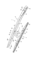
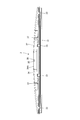
- FIG. 1 to 5 show an overall configuration of a wiper assembly 1 according to an embodiment of the present invention.
- the wiper assembly 1 includes a wiper arm 2 and a wiper blade 3 held by the wiper arm 2.
- the wiper arm 2 includes a base end side arm head 21 and an arm main body 23 that is rotatably connected to the arm head 21 via a connecting pin 22.
- the arm head 21, the connecting pin 22, and the arm main body 23 are all made of metal.
- the arm head 21 is covered with a head cover 21A.
- a spring 24 is provided between the arm head 21 and the arm main body 23. Accordingly, when the wiper assembly 1 is used, the spring 24 gives an appropriate force to the rotation of the arm body 23 around the connecting pin 22, and as a result, the wiper blade 3 supported by the arm body 23 is The wiping surface (for example, a glass surface of an automobile) is pressed against the surface to be wiped with an appropriate pressing force.
- the arm body 23 is a long member that constitutes a main part of the wiper arm 2, and includes a top wall 25 and side walls 26 on both sides extending downward from both longitudinal sides of the top wall 25.
- the space surrounded by the top wall 25 and the side walls 26 serves as a blade accommodating portion 27 that accommodates the support portion 32 of the wiper blade 3.
- a clip mounting portion 28 to which the clip member 4 is mounted is provided at a substantially central portion in the longitudinal direction of the blade housing portion 27.
- the clip mounting portion 28 is provided with a pair of holding pieces 29 for holding the mounted clip member 4.
- Each holding piece 29 extends from the lower end edge 26 ⁇ / b> A of each side wall 26 toward the opposite side wall 26 at a right angle to the side wall 26.
- the wiper blade 3 includes a blade portion 31 and a support portion 32 that supports the blade portion 31 from above.
- the blade part 31 is a long wiping member for wiping the surface to be wiped, and is made of rubber.
- the support portion 32 is a long member having substantially the same length as the blade portion 31, and is entirely formed of resin.
- a plurality of claw parts 33 extending downward are provided at the main points of the support part 32, and the blade part 31 is supported by these claw parts 33.
- connection recessed part 35 is formed in the longitudinal direction approximate center part of the both sides
- Each connection recess 35 is formed in the vicinity of the upper end edge 34 ⁇ / b> A of each side surface 34, and an introduction groove 36 is formed between each connection recess 35 and the upper end edge 34 ⁇ / b> A.
- a plurality of protrusions 37 are formed on the side walls 34 on both sides of the support portion 32.
- a total of four protrusions 37 are provided, one on each side of the connecting recess 35 in the longitudinal direction.
- the contact area between the wiper blade 3 and the wiper arm 2 is the protrusion 37, so that the contact area between the wiper blade 3 and the wiper arm 2 can be reduced. Therefore, since the frictional resistance during the rotation of the wiper blade 3 can be reduced, the proper rotation operation of the wiper blade 3 is not hindered when the wiper assembly 1 is used. .
- the protrusion 37 is located at a position farthest from the connecting recess 35 in the longitudinal direction within a range in which the wiper blade 3 continues to contact the inward surface 26B of the side wall 26 of the arm body 23 when the wiper blade 3 rotates with respect to the wiper arm 2. Provided. Accordingly, when a lateral external force is applied to the wiper blade 3, the external force is received at the projection 37 at a position sufficiently away from the connection concave portion 35 that is a fulcrum. Can be reduced, and breakage of the support portion 32 can be appropriately prevented.
- the clip member 4 is a U-shaped member composed of a top wall 41 and side walls 42 on both sides, and just fits into the clip mounting portion 28 of the arm body 23. It has such a size and shape. Further, the clip member 4 has a certain degree of flexibility, and each side wall 42 of the clip member 4 can be bent toward the opposite side wall 42. In the present embodiment, the clip member 4 is formed by resin molding.
- Connection protrusions 43 project from the inward surfaces 42A of the side walls 42 on both sides of the clip member 4, respectively. By fitting these connecting projections 43 into the connecting recesses 35 of the wiper blade 3, the wiper blade 3 is connected to the wiper arm 2 via the clip member 4, and the wiper blade 3 is connected to the wiper arm 2. It is supported so as to be rotatable around the connecting projection 43.
- a downwardly inclined portion 43 ⁇ / b> A is formed at the top of each connecting convex portion 43.
- a notch 44 is formed in the lower end edge 42B of the side wall 42 of the clip member 4.
- FIG. 14 to 16 show a mounting procedure for mounting the clip member 4 in the clip mounting portion 28 of the arm body 23.
- FIG. 14 In mounting the clip member 4, as shown in FIG. 14, the clip member 4 is inserted into the blade accommodating portion 27 of the arm body 23 from the top wall 41 side.
- the insertion position of the clip member 4 is not the clip mounting portion 28 but a position adjacent to the clip mounting portion 28 in the longitudinal direction as shown in FIG. Thereby, the clip member 4 does not interfere with the holding piece 29 of the arm body 23 during the insertion operation.
- the clip member 4 is slid toward the clip mounting portion 28.
- the clip member 4 moves through the holding piece 29 provided in the clip mounting portion 28 and moves into the clip mounting portion 28. I can go.
- the holding piece 29 is moved into the notch portion 44 of the clip member 4 by returning the bending of the side walls 42 of the clip member 4 to the original state. Mating. Thereby, the clip member 4 is appropriately held in the clip mounting portion 28 by the holding piece 29.
- the resin support portion 32 of the wiper blade 3 is accommodated in the blade accommodating portion 27 of the metal wiper arm 2. Therefore, the support portion 32 of the wiper blade 3 is appropriately protected by the arm body 23 having a large structural strength. Accordingly, by using the light and inexpensive resin support portion 32, the overall weight of the wiper assembly 1 can be reduced and the manufacturing cost can be reduced, and the structural strength of the wiper assembly 1 can be secured. be able to.
- a plurality of protrusions 37 are provided on the support part 32 of the wiper blade 3, and the protrusions 37 come into contact with the inward surface 24 ⁇ / b> A of the side wall 24 of the arm body 23. Is held at an appropriate position in the blade accommodating portion 27 without rattling. As a result, damage to the wiper blade 3 due to rattling can be effectively prevented, and the structural strength of the wiper assembly 1 can be increased. Further, the contact portion between the wiper blade 3 and the wiper arm 2 is only the projecting portion 37, and the contact area can be minimized, so that the frictional resistance to the rotational movement of the wiper blade 3 is reduced, and the wiper assembly 1 is used. Thus, it is possible to ensure proper rotation of the wiper blade 3.
- the protrusion 37 is farthest from the connecting recess 35 in the longitudinal direction within a range in which the protrusion 37 continues to contact the inward surface 26B of the side wall 26 of the arm body 2 when the wiper blade 3 rotates with respect to the wiper arm 2. Since it is provided at the position, when a lateral external force acts on the wiper blade 3, the external force is received at the projection 37 located far from the connecting concave portion 35 as a fulcrum. . As a result, the load applied to the support portion 32 can be reduced, and breakage of the wiper blade 3 can be prevented appropriately.
- the projection 37 is provided on the side surface 34 of the support portion 32.
- the present invention is not limited to such a configuration, and the projection is provided on the side wall of the arm body 23.
- 26 may be provided on the inward surface 26 ⁇ / b> B of the 26, and the protrusion may be in contact with the side surface 34 of the support portion 32.
- the support portion 32 of the wiper blade 3 holds the blade portion 31 by the plurality of claw portions 33, but the present invention is not limited to such a form.
- the wiper blade 3 may be one in which a support portion and a blade portion are integrally formed.
- the wiper blade 3 is attached to the wiper arm 2 via the clip member 4, this invention is not limited to such a form,
- a wiper blade The clip member 4 may not be provided between the wiper arm 3 and the wiper arm 2, and the wiper blade 3 may be directly attached to the wiper arm 2 via a connecting shaft such as a rivet.
Landscapes
- Engineering & Computer Science (AREA)
- Mechanical Engineering (AREA)
- Ink Jet (AREA)
- Brushes (AREA)
- Insertion Pins And Rivets (AREA)
Abstract
L'objectif de la présente invention est de produire un ensemble essuie-glace comprenant un bras d'essuie-glace pour retenir un balai d'essuie-glace dans un état où au moins une partie du balai d'essuie-glace est rangée dans une section de rangement de balai, grâce auquel il est possible de réduire le poids et de diminuer les coûts de production. L'invention concerne un ensemble essuie-glace 1 dans lequel une section support 32 d'un balai 3 d'essuie-glace est rangée dans une section de rangement 27 de balai située sur un corps principal 23 de bras d'un bras 2 d'essuie-glace et le balai 3 d'essuie-glace est retenu avec le bras 2 d'essuie-glace, le corps principal 23 de bras étant composé de métal tandis que la section support 32 est composée de résine. Une pluralité de saillies 37 sont disposées sur une surface latérale 34 de la section support 32, et ces saillies 37 sont amenées à entrer en contact avec une surface orientée vers l'intérieur 26B d'une paroi latérale 26 du corps principal 23 de bras.
Priority Applications (3)
| Application Number | Priority Date | Filing Date | Title |
|---|---|---|---|
| US15/747,957 US20180222447A1 (en) | 2015-07-27 | 2016-07-26 | Wiper assembly |
| EP16830535.7A EP3330138A4 (fr) | 2015-07-27 | 2016-07-26 | Ensemble essuie-glace |
| CN201680043909.2A CN107848494A (zh) | 2015-07-27 | 2016-07-26 | 雨刷组件 |
Applications Claiming Priority (2)
| Application Number | Priority Date | Filing Date | Title |
|---|---|---|---|
| JP2015148170A JP6055044B1 (ja) | 2015-07-27 | 2015-07-27 | ワイパー組み立て体 |
| JP2015-148170 | 2015-07-27 |
Publications (1)
| Publication Number | Publication Date |
|---|---|
| WO2017018430A1 true WO2017018430A1 (fr) | 2017-02-02 |
Family
ID=57582269
Family Applications (1)
| Application Number | Title | Priority Date | Filing Date |
|---|---|---|---|
| PCT/JP2016/071939 Ceased WO2017018430A1 (fr) | 2015-07-27 | 2016-07-26 | Ensemble essuie-glace |
Country Status (5)
| Country | Link |
|---|---|
| US (1) | US20180222447A1 (fr) |
| EP (1) | EP3330138A4 (fr) |
| JP (1) | JP6055044B1 (fr) |
| CN (1) | CN107848494A (fr) |
| WO (1) | WO2017018430A1 (fr) |
Families Citing this family (4)
| Publication number | Priority date | Publication date | Assignee | Title |
|---|---|---|---|---|
| USD933574S1 (en) * | 2019-07-09 | 2021-10-19 | Trico Belgium Sa | Windshield wiper |
| USD928067S1 (en) * | 2019-07-09 | 2021-08-17 | Trico Belgium Sa | Windshield wiper |
| USD928066S1 (en) * | 2019-07-09 | 2021-08-17 | Trico Belgium Sa | Wiper assembly |
| USD974273S1 (en) * | 2019-07-09 | 2023-01-03 | Trico Belgium, SA | Windshield wiper |
Citations (3)
| Publication number | Priority date | Publication date | Assignee | Title |
|---|---|---|---|---|
| JP2004203180A (ja) * | 2002-12-25 | 2004-07-22 | Asmo Co Ltd | ウォッシャノズル付ワイパ |
| JP2008168796A (ja) * | 2007-01-12 | 2008-07-24 | Mitsuba Corp | 車両用ワイパ装置 |
| JP3178011U (ja) * | 2004-10-18 | 2012-08-30 | フェデラル−モーグル ソシエテ アノニム | ウィンドスクリーン用ワイパ・アーム |
Family Cites Families (25)
| Publication number | Priority date | Publication date | Assignee | Title |
|---|---|---|---|---|
| US1475287A (en) * | 1922-09-05 | 1923-11-27 | Patrick J Dever | Shoe-soling tool |
| US1641683A (en) * | 1922-11-20 | 1927-09-06 | Trico Products Corp | Windshield cleaner |
| US2240264A (en) * | 1936-12-31 | 1941-04-29 | Gillette Safety Razor Co | Shaving implement |
| US2660267A (en) * | 1950-06-02 | 1953-11-24 | Illinois Railway Equipment Co | Brakehead wear plate and key wedge |
| US3866260A (en) * | 1973-10-17 | 1975-02-18 | Gates Rubber Co | Low silhouette connector for windshield wiper blades |
| US3925844A (en) * | 1974-07-15 | 1975-12-16 | Gates Rubber Co | Fiber-loaded windshield wiper superstructure |
| US5195571A (en) * | 1991-02-25 | 1993-03-23 | General Motors Corporation | Method of die cast molding metal to fiber reinforced fiber plastic |
| FR2717757B1 (fr) * | 1994-03-23 | 1996-05-15 | Journee Paul Sa | Essuie-glace de véhicule automobile comportant des moyens de guidage transversal du balai d'essuie-glace par rapport au bras d'essuie-glace. |
| FR2768677B1 (fr) * | 1997-09-19 | 1999-10-15 | Valeo Systemes Dessuyage | Essuie-glace de vehicule automobile comportant des moyens perfectionnes d'articulation d'un balai d'essuie-glace sur un bras d'essuie-glace |
| WO1999037513A1 (fr) * | 1998-01-20 | 1999-07-29 | Robert Bosch Gmbh | Bras de monture d'essuie-glace |
| FR2782043B1 (fr) * | 1998-08-07 | 2000-09-15 | Valeo Systemes Dessuyage | Essuie-glace de vehicule automobile comportant des moyens perfectionnes d'articulation et de verrouillage d'un balai d'essuie-glace sur un bras d'essuie-glace |
| FR2788027B1 (fr) * | 1998-12-30 | 2001-02-23 | Valeo Systemes Dessuyage | Essuie-glace de vehicule automobile comportant des moyens perfectionnes d'articulation du balai sur le bras d'essuie-glace |
| DE19952054A1 (de) * | 1999-10-28 | 2001-05-03 | Bosch Gmbh Robert | Wischvorrichtung für Scheiben von Kraftfahrzeugen |
| DE10194663D2 (de) * | 2000-10-28 | 2003-10-02 | Bosch Gmbh Robert | Vorrichtung zum lösbaren, gelenkigen Verbinden eines Wischblatts zum Reinigen von Scheiben mit einem Wischerarm |
| DE10065124A1 (de) * | 2000-12-28 | 2002-07-04 | Bosch Gmbh Robert | Vorrichtung zum lösbaren Verbinden eines Wischblatts mit einem Wischerarm |
| US6675430B2 (en) * | 2001-09-12 | 2004-01-13 | Asmo Co., Ltd. | Wiper device for vehicle having wiper blade lifting mechanism |
| FR2847221B1 (fr) * | 2002-11-19 | 2006-08-04 | Valeo Systemes Dessuyage | Essuie-glace de vehicule comportant un bras et un connecteur d'articulation realises d'une piece par moulage en matiere plastique |
| EP1584528B1 (fr) * | 2004-04-06 | 2008-03-19 | HONDA MOTOR CO., Ltd. | Dispositif d'essuie-glace et structure de balai |
| JP2005297600A (ja) * | 2004-04-06 | 2005-10-27 | Honda Motor Co Ltd | ワイパーブレード連結構造 |
| DE102008000626A1 (de) * | 2008-03-12 | 2009-09-17 | Robert Bosch Gmbh | Vorrichtung zum gelenkigen Verbinden eines Wischblatts |
| DE102008038981A1 (de) * | 2008-08-13 | 2010-02-18 | Volkswagen Ag | Scheibenwischer an einem Fahrzeug |
| US9073520B2 (en) * | 2010-07-28 | 2015-07-07 | Teklas Kaucuk Sanayi Ve Ticaret A.S. | Connecting device for windscreen wipers |
| DE102011001688A1 (de) * | 2011-03-31 | 2012-10-04 | Valeo Systèmes d'Essuyage | Wischblatt und Wischvorrichtung zum Reinigen von Fahrzeugscheiben |
| US9145111B2 (en) * | 2012-09-10 | 2015-09-29 | Alberee Products, Inc. | Hybrid blade |
| US9604598B2 (en) * | 2015-07-09 | 2017-03-28 | GM Global Technology Operations LLC | Wiper arm pin release for service |
-
2015
- 2015-07-27 JP JP2015148170A patent/JP6055044B1/ja active Active
-
2016
- 2016-07-26 EP EP16830535.7A patent/EP3330138A4/fr not_active Withdrawn
- 2016-07-26 CN CN201680043909.2A patent/CN107848494A/zh active Pending
- 2016-07-26 WO PCT/JP2016/071939 patent/WO2017018430A1/fr not_active Ceased
- 2016-07-26 US US15/747,957 patent/US20180222447A1/en not_active Abandoned
Patent Citations (3)
| Publication number | Priority date | Publication date | Assignee | Title |
|---|---|---|---|---|
| JP2004203180A (ja) * | 2002-12-25 | 2004-07-22 | Asmo Co Ltd | ウォッシャノズル付ワイパ |
| JP3178011U (ja) * | 2004-10-18 | 2012-08-30 | フェデラル−モーグル ソシエテ アノニム | ウィンドスクリーン用ワイパ・アーム |
| JP2008168796A (ja) * | 2007-01-12 | 2008-07-24 | Mitsuba Corp | 車両用ワイパ装置 |
Non-Patent Citations (1)
| Title |
|---|
| See also references of EP3330138A4 * |
Also Published As
| Publication number | Publication date |
|---|---|
| US20180222447A1 (en) | 2018-08-09 |
| EP3330138A1 (fr) | 2018-06-06 |
| JP6055044B1 (ja) | 2016-12-27 |
| CN107848494A (zh) | 2018-03-27 |
| JP2017024672A (ja) | 2017-02-02 |
| EP3330138A4 (fr) | 2019-03-27 |
Similar Documents
| Publication | Publication Date | Title |
|---|---|---|
| US8671505B2 (en) | Windshield wiper blade assembly | |
| JP5613047B2 (ja) | 自動車のワイパブレード用コネクタのアダプタおよび連結ベース | |
| CN103459211B (zh) | 刮水片适配器装置 | |
| CN103492241B (zh) | 刮水片适配器装置 | |
| CN108541176B (zh) | 用于固定电子装置的托架和用于固定电子装置的机构 | |
| JP6055044B1 (ja) | ワイパー組み立て体 | |
| US9862356B2 (en) | Wiper blade | |
| WO2014208541A1 (fr) | Bras d'essuie-glace | |
| JP6175444B2 (ja) | 車両用ワイパ | |
| JP5138531B2 (ja) | 車両用ワイパ | |
| WO2015099117A1 (fr) | Connecteur | |
| JP6017647B1 (ja) | ワイパー組み立て体 | |
| JP6093029B2 (ja) | サンバイザ用バネおよびサンバイザ用支持装置 | |
| JP2016011105A (ja) | ワイパーブレード | |
| WO2014077250A1 (fr) | Balai d'essuie-glace | |
| US20020174504A1 (en) | Adapter for windshield wiper arms | |
| JP6684322B2 (ja) | ワイパーブレード用カバー部材 | |
| CN105644513B (zh) | 刮水片用转接器及其刮水片组件 | |
| JP4779867B2 (ja) | ワイパー装置 | |
| JP6584585B1 (ja) | ワイパーブレード | |
| TWM499348U (zh) | 刮水片用轉接器及其刮水片組件 | |
| JP2014102284A (ja) | ハウジング接続構造 | |
| JP6620070B2 (ja) | ワイパブレード | |
| JP2007022359A (ja) | ワイパーアーム用ストッパ部材及びワイパーアーム | |
| JP2014088143A (ja) | 車両用リヤワイパ |
Legal Events
| Date | Code | Title | Description |
|---|---|---|---|
| 121 | Ep: the epo has been informed by wipo that ep was designated in this application |
Ref document number: 16830535 Country of ref document: EP Kind code of ref document: A1 |
|
| WWE | Wipo information: entry into national phase |
Ref document number: 15747957 Country of ref document: US |
|
| NENP | Non-entry into the national phase |
Ref country code: DE |
|
| WWE | Wipo information: entry into national phase |
Ref document number: 2016830535 Country of ref document: EP |