WO2017018532A1 - Dispositif de circulation d'air - Google Patents
Dispositif de circulation d'air Download PDFInfo
- Publication number
- WO2017018532A1 WO2017018532A1 PCT/JP2016/072420 JP2016072420W WO2017018532A1 WO 2017018532 A1 WO2017018532 A1 WO 2017018532A1 JP 2016072420 W JP2016072420 W JP 2016072420W WO 2017018532 A1 WO2017018532 A1 WO 2017018532A1
- Authority
- WO
- WIPO (PCT)
- Prior art keywords
- air
- housing
- heat exchange
- circulation device
- air circulation
- Prior art date
- Legal status (The legal status is an assumption and is not a legal conclusion. Google has not performed a legal analysis and makes no representation as to the accuracy of the status listed.)
- Ceased
Links
Images






Classifications
-
- A—HUMAN NECESSITIES
- A41—WEARING APPAREL
- A41D—OUTERWEAR; PROTECTIVE GARMENTS; ACCESSORIES
- A41D13/00—Professional, industrial or sporting protective garments, e.g. surgeons' gowns or garments protecting against blows or punches
- A41D13/002—Professional, industrial or sporting protective garments, e.g. surgeons' gowns or garments protecting against blows or punches with controlled internal environment
- A41D13/005—Professional, industrial or sporting protective garments, e.g. surgeons' gowns or garments protecting against blows or punches with controlled internal environment with controlled temperature
-
- A—HUMAN NECESSITIES
- A62—LIFE-SAVING; FIRE-FIGHTING
- A62B—DEVICES, APPARATUS OR METHODS FOR LIFE-SAVING
- A62B17/00—Protective clothing affording protection against heat or harmful chemical agents or for use at high altitudes
- A62B17/04—Hoods
-
- F—MECHANICAL ENGINEERING; LIGHTING; HEATING; WEAPONS; BLASTING
- F24—HEATING; RANGES; VENTILATING
- F24F—AIR-CONDITIONING; AIR-HUMIDIFICATION; VENTILATION; USE OF AIR CURRENTS FOR SCREENING
- F24F1/00—Room units for air-conditioning, e.g. separate or self-contained units or units receiving primary air from a central station
- F24F1/02—Self-contained room units for air-conditioning, i.e. with all apparatus for treatment installed in a common casing
- F24F1/04—Arrangements for portability
-
- F—MECHANICAL ENGINEERING; LIGHTING; HEATING; WEAPONS; BLASTING
- F24—HEATING; RANGES; VENTILATING
- F24F—AIR-CONDITIONING; AIR-HUMIDIFICATION; VENTILATION; USE OF AIR CURRENTS FOR SCREENING
- F24F13/00—Details common to, or for air-conditioning, air-humidification, ventilation or use of air currents for screening
- F24F13/22—Means for preventing condensation or evacuating condensate
Definitions
- the present invention relates to a portable air circulation device that can be worn by an operator.
- cooling air is applied to the human body (for example, refer to Patent Document 1).
- the cooling medium has a function as an air circulation device by blowing air in a state where moisture contained in the air is removed by condensation instead of simply cooling the air.
- the above-described technique does not have a function of collecting the water droplets when the water contained in the air is condensed by cooling the air with such a cooling medium.
- An object of the present invention is to provide an air circulation device capable of collecting water droplets in order to solve the above-described problems.
- an air circulation device includes a housing that houses a heat exchange member therein, an intake port that is formed in the housing so as to be located upstream of the heat exchange member, and a heat An exhaust port formed in the housing so as to be positioned downstream of the replacement member, and an exhaust hose connected at one end to the exhaust port and extending along at least a part of the human body, from the intake port
- the human body uses the cooling air from which moisture contained in the air is dehumidified by the endothermic action of the heat exchange member by releasing the air taken into the housing from the exhaust port to the exhaust hose while absorbing heat by the endothermic action of the heat exchange member
- a water droplet collection path for collecting water droplets generated by dehumidification is formed below the housing.
- a cooling medium for the heat exchange member it is preferable to use a cooling medium for the heat exchange member to cool the air.
- the water droplet recovery path includes an inclined guide wall formed inside the housing and below the cooling medium, a nozzle provided at the lowest position of the inclined guide wall, a recovery hose having one end connected to the nozzle, a recovery hose, and the like. And a collection bag connected to the end.
- the intake path from the intake port to the cooling medium is formed on the downstream side of the inclined guide wall.
- a suction fan that forcibly introduces air from the intake port is disposed inside the housing and downstream of the cooling medium and upstream of the exhaust port.
- the exhaust hose has an exhaust hose with one end connected to the exhaust port, the exhaust hose has exhaust holes along the extending direction and at a predetermined interval, and the exhaust holes are out of phase with each other adjacent in the extending direction. It is a thing.
- water drops can be collected by providing a water drop collection path.
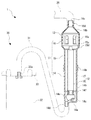
- FIG. 1 An example of the arrangement of the exhaust hose when the work clothes are the best is shown, (A) is an explanatory diagram of an example of the hose arrangement on the front side of the vest, and (B) is an explanatory diagram of an example of the hose arrangement on the back side of the vest. is there.
- the air circulation device 1 is mounted between an inner cloth such as a vest V worn by an operator (human body) P and an outer cloth (both not shown).
- the air circulation device 1 can be used in any form, for example, one that is detachably attached to clothing such as various chemical protective clothing or fire fighting clothing, or one that is carried on the shoulder by a shoulder belt (not shown). is there. Further, the air circulation device 1 can be detachably attached to the vest V so as to be lowered from the bottom of the vest V, for example.
- the air circulation device 1 includes an air circulation device main body 10 for cooling the sucked air, an exhaust hose 20 for circulating the air cooled by the air circulation device main body 10 to the upper body (or the whole body) of the worker P, A water droplet recovery unit 30 that recovers water droplets generated inside the air circulation device main body 10.
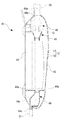
- the air circulation device main body 10 includes a housing 11 having a predetermined shape, a cooling medium 12 housed in the housing 11, and a pair of suction fans housed in the housing 11. 13. Although illustration is omitted, inside the housing 11, a power source such as a battery for supplying power to the suction fan 13, a control circuit for controlling the drive of the suction fan 13, and the cooling medium 12 are protected from external heat. Insulating material etc. are stored. At this time, at least the power supply and the control circuit are housed in an internal space that is isolated from the cooling medium 12 inside the housing 11.
- each case 14, 15, 16 is made of synthetic resin or the like so that the internal structure or the like can be molded into a predetermined shape. In the state, it may be divided at appropriate positions on the inner side (for example, the human body side on the left side of FIG. 3) and on the outer side (for example, the right side of FIG. 3).
- the resin material of the housing 11 for example, a synthetic resin material of aramid fiber reinforced plastic and FRP (fiber reinforced plastic) is used, and the rigidity of the housing 11 is ensured while ensuring the compactness and weight reduction as a whole. It is desirable to do.
- the resin material of the housing 11 is not limited to the above, for example, priority is given to heat resistance over weight reduction.
- the lower case 14 integrally includes a bottom wall 14a and a peripheral wall 14b that rises from the peripheral edge of the bottom wall 14a so as to open upward and opens at the upper end.
- the bottom wall 14a integrally includes an inclined guide wall 14c that expands upward from the inner surface side and a nozzle 14d that protrudes downward from the center in the width direction (the left-right direction in FIG. 2).
- the peripheral wall 14b includes an intake port 14e that opens to the lower side of both side surfaces in the width direction (the left-right direction in FIG. 2), a holder portion 14f that bends downward from the inner wall surface in a substantially L shape, and the holder portion 14f It integrally has a flange portion 14g that covers a part of the inclined guide wall 14c from the lower end in a spaced state and an engagement portion 14h that widens the vicinity of the upper end outward.
- the upper case 15 integrally has an upper wall 15a and a peripheral wall 15b that falls from the peripheral edge of the upper wall 15a to the inside of the engaging portion 14h in an inlay manner and opens at the lower end.
- the upper wall 15a is positioned near both ends in the width direction (the left-right direction in FIG. 2) and is opened toward the center and both ends in the width direction from the pair of communication openings 15c that open in a substantially circular shape.
- the fan storage case 16 is independently affirmed by the upper case 15 in correspondence with the pair of communication ports 15c.
- the fan storage case 16 includes a columnar storage portion 16a that opens at the lower end so as to communicate with the communication port 15c, a compression portion 16b that decreases in diameter from the upper end of the storage portion 16a, and an upper end of the compression portion 16b.
- An exhaust nozzle 16d that protrudes to open the exhaust port 16c at the tip and a thick fixed portion 16e that is screwed to the fixing portion 15e are integrally provided.
- the cooling medium 12 includes a pair of fins 17 and a case-shaped gel container 18 that houses the pair of fins 17 therein.
- the fin 17 has a plurality of partition walls (not shown) inclined alternately in opposite directions with respect to the width direction of the hollow interior.
- the partition wall may have a continuous shape without a cut from the bottom to the top inside the fin 17 or may have a discontinuous shape with a break.
- the partition wall preferably has a continuous (or non-continuous) structure, for example, in a saw blade shape or a corrugated shape. 17 may be formed in a straight line along the vertical direction.
- the fins 17 may be made by solidifying a known gel-like cryogen (also referred to as “gel-like cryogen”) by freezing.
- the gel container 18 is made of a lightweight metal such as a resin container or an aluminum block to ensure the cooling effect of the fins 17.
- the gel container 18 covers the entire outer surface except for the vicinity of the lower end and the vicinity of the upper end of the fin 17 inside the casing 11.
- the gel container 18 is made of different materials depending on the material of the fins 17. For example, when a metal block is used for the fin 17, the gel container 18 uses a resin hollow container to ensure the cooling effect of the fin 17.
- a resin container having a hollow structure in the thickness direction is used, and, for example, a gel-like cold insulating agent is injected into the hollow interior in a state where the surface of the fin 17 having a metal block shape is covered. For this reason, the gel container 18 is provided with an injection port (not shown) for injecting the gel-like cooling agent on the side surface side.
- Gel cooling agent is injected (filled) into the gel container 18 and frozen and solidified to cool the air passing through the inside of the fins 17 along the partition walls to produce cooling air.
- the suction fan 13 is disposed inside the housing 11 and downstream of the cooling medium 12 and upstream of the exhaust port 16c. As a result, the air forcedly introduced from the intake port 14 e is cooled by passing through the cooling medium 12 (particularly the fins 17), and then discharged from the exhaust port 16 c to the exhaust hose 20.
- the suction fan 13 may be any type of an axial fan (for example, a propeller fan) and a centrifugal fan (for example, a sirocco fan or a turbo fan).
- one end of the exhaust hose 20 is connected to the exhaust port 16c, and the other end extends to a predetermined position of the vest V.
- the exhaust hose 20 extends from the back side of the worker P to the vicinity of the stomach of the worker P via both shoulders.
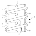
- the exhaust hose 20 includes an exhaust hole 21 penetrating in the thickness direction along the extending direction and at a predetermined interval. The phases of the exhaust holes 21 adjacent to each other in the extending direction are shifted by 90 °.
- the vest V is provided with, for example, a cushion body or the like having a thickness between the inner cloth and the outer cloth and allowing air to flow. Thereby, the air after cooling discharged from each exhaust hole 21 of the exhaust hose 20 between the inner cloth and the outer cloth travels uniformly to the vest V, or cools the entire upper body of the worker P who is a human body. be able to.
- the water droplet recovery unit 30 includes a recovery hose 31 having one end connected to the nozzle 14d, a recovery bag 32 having the other end of the recovery hose 31 connected to a receiving port 32a, and a recovery bag 32. And a belt 33 to be worn around the waist.
- the air taken in from the intake port 14e is formed so as to be guided from the lower end (upstream end) of the fin 17 to the inside of the fin 17 to secure the intake path.
- An intake path from the intake port 14e to the cooling medium 12 (lower end of the fin 17) is formed on the downstream side of the inclined guide wall 14c.
- the air circulation device 1 includes a housing 11 in which the cooling medium 12 is housed, an intake port 14e formed in the housing 11 so as to be positioned upstream of the cooling medium 12, and a cooling device.
- the air taken into the housing 11 from the intake port 14e is heat-exchanged (cooled) by the cooling medium 12, and then discharged from the exhaust port 16c to the exhaust hose 20, whereby moisture contained in the air is removed from the cooling medium 12.
- dehumidification means “condensation” generated by cooling the air. Therefore, in the following description, “condensation” means “condensation” as an action for removing a part of moisture contained in air, and “water droplets” means water drops generated by the condensation action. Means.
- the suction fan 13 when the suction fan 13 is driven, air is taken in from the air inlet 14e, and cooling air is blown toward the upper body of the worker P via the cooling medium 12.
- the air taken in from the outside of the housing 11 through the air inlet 14e by the drive of the suction fan 13 mainly takes the lower end of the fin 17 (the lower end of the fin 17 as an intake path between the inclined guide wall 14c and the flange 14g). After being guided to the upstream end), the air is cooled while passing through the fins 17, and the cooling air is exhausted from the exhaust holes 21 of the exhaust hose 20 through the exhaust ports 16 c.
- the cooling medium 12 realizes a dry function for dehumidifying the air.
- the vest V is worn by the air circulation device 1 by sucking air from the air inlet 14e inside the vest V and circulating it while dehumidifying it through the cooling medium 12 by the suction fan 13.
- the body of the worker P who has performed can be effectively cooled and simultaneously provided with a dehumidifying effect.
- the air circulation device 1 causes the air inside the vest V and the air outside the air circulation device 1 to be discharged from the air intake port 14 e by the intake air pressure on the intake side of the suction fan 13. Take it inside.
- the taken-in air passes between the plurality of partition walls in the fin 17 along the path length direction by the intake pressure on the intake side of the suction fan 13.
- the fin 17 cools the air that passes by transmitting the cold air of the gel-type cryogen filled in the gel container 18 to the fin 17 and simultaneously dehumidifies the air that passes by generating condensation on the surface.
- the cooling air cooled together with the dehumidification is sent to the exhaust port 16c by the exhaust pressure on the exhaust side of the suction fan 13, and from outside the air circulation device 1 through the exhaust holes 21 of the exhaust hose 20 from the exhaust port 16c. It discharges into the inside of a certain best V.
- the inner surface and the outer surface of the fin 17 and the outer surface of the gel container 18 have moisture content contained in the air, particularly due to the difference between the surface temperature and the temperature of the air before cooling. Remove by condensing part.
- the water droplets due to the condensation fall down through the inner surface and outer surface of the fin 17 and the outer surface of the gel container 18, and are guided to the nozzle 14d while being guided by the flange 14g or the inclined guide wall 14c. It is collected in a collection bag 32 via a collection hose 31 having one end connected to 14d.
- the air circulation device 1 can collect water droplets generated on the surface of the cooling medium 12 by providing the water droplet collection path.
- the housing 11 is divided into the lower case 14, the upper case 15, and the fan storage case 16.
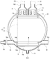
- FIG. 6 and FIG. 6 the housing 41 is attached to the body 42 on the human body side (the left side in the drawing in FIG. 6) on the inner surface side and the surface side (the right side in the drawing in FIG. 6).
- the air circulation apparatus main body 40 of the structure comprised by dividing into 2 parts with the cover part 43, and attaching the cover part 43 to the main-body part 42 so that opening and closing is possible.
- the functionally same configuration as the air circulation device main body 10 is denoted by the same reference numeral, and detailed description thereof is omitted.
- the main body 42 and the lid 43 are preferably formed of a synthetic material of aramid fiber reinforced plastic and FRP (fiber reinforced plastic), respectively. Thereby, rigidity is securable, making the whole housing
- a water droplet collection member 44 positioned below the cooling medium 12
- a gel container 18 covering the outer surface of the cooling medium 12
- a duct member 45 positioned above the cooling medium 12.
- the fan case 46 communicating with the duct member 45 is configured separately and stored.
- the water droplet recovery member 44 protrudes downward from the center in the width direction, an upper end opening 44a that also serves as a holding portion on the lower end side of the cooling medium 12, an inclined guide wall 44b that expands upward from the inner surface side.
- the nozzle 44c to which the recovery hose 31 is integrally connected and the intake communication port 44d for allowing the air taken in from the intake port 14e to communicate with the fins 17 are integrally provided.
- the duct member 45 is also used as a holding portion on the upper end side of the cooling medium 12 and guides the cooling air that has passed through the fins 17 toward the suction fan 13.
- the fan case 46 holds the suction fan 13 and integrally includes an exhaust nozzle 46b that opens an exhaust port 46a at the tip so as to discharge the cooling air passing through the duct member 45 toward the exhaust hose 20.
- One end of the exhaust hose 20 is connected to the exhaust nozzle 46b.
- the air circulation device 1 includes the casing 41 that houses the cooling medium 12 therein, the intake port 14e formed in the casing 41 so as to be positioned upstream of the cooling medium 12, and the cooling An exhaust port 46a formed in the housing 41 so as to be located downstream of the medium 12, and an exhaust hose 20 connected to the exhaust port 46a and extending along the human body of the worker P.
- the air taken into the housing 11 from the air inlet 14e is absorbed by the heat absorbing action of the cooling medium 12 and released from the air outlet 46a to the exhaust hose 20, so that moisture contained in the air is absorbed by the cooling medium 12.
- the surface of the cooling medium 12 is supplied to the human body as cooling air dehumidified by the action, and a water droplet collection path for collecting water droplets generated on the surface of the cooling medium 12 is formed below the housing 41. It can be recovered generated water droplets.
- each exhaust hole 21 of the exhaust hose 20 passes from the outside of the housing 11 through the intake port 14 e, between the fin 17 and the gel container 18, and the exhaust port 46 a in this order. Exhaust cooling air from
- the vest V is a worker who wears the vest V by sucking air from the air inlet 14e by the air circulation device 1 and circulating the air through the cooling medium 12 by the suction fan 13. P's body can be effectively cooled.
- the vest V is a state in which the air circulation device 1 is disposed between the human body and the outer cloth even with only the outer cloth having no inner cloth, thereby taking in air between the human body and the outer cloth and performing dehumidification. Furthermore, the air can be circulated by discharging it toward the human body in a cooled state. In addition, when working with high-tight work clothes or protective clothes instead of the vest V, depending on the type of the work clothes, for example, air is applied to the upper body of the human body or the whole body of the human body. It can be circulated.
- the air circulation device 1 causes the air inside the vest V and the air outside the air circulation device 1 to be discharged from the air intake port 14 e by the intake air pressure on the intake side of the suction fan 13. Take it inside.
- the taken-in air passes between the plurality of partition walls in the fin 17 along the path length direction by the intake pressure on the intake side of the suction fan 13.
- the fin 17 cools the air that passes by transmitting the cold air of the gel-type cryogen filled in the gel container 18 to the fin 17 and simultaneously dehumidifies the air that passes by generating condensation on the surface.
- the cooling air cooled together with the dehumidification is sent to the exhaust port 46 a by the exhaust pressure on the exhaust side of the suction fan 13, and from the exhaust port 46 a via the exhaust holes 21 of the exhaust hose 20 to the outside of the air circulation device 1. It discharges into the inside of a certain best V.
- the water droplets fall down through the inner surface and outer surface of the fin 17 and the outer surface of the gel container 18, and are guided to the nozzle 44c while being guided by the inclined guide wall 44b, and have one end connected to the nozzle 44c. It is collected in a collection bag 32 via a collection hose 31.
- the air taken in from the intake port 14e is formed as an intake communication port 44d so as to be led from the lower end (upstream end) of the fin 17 to the inside of the fin 17 to secure an intake path.
- An intake path from the intake port 14e to the cooling medium 12 (lower end of the fin 17) is formed on the downstream side of the inclined guide wall 14c.
- the air circulation device 1 can collect water droplets generated on the surface of the cooling medium 12 by providing the water droplet collection path.
- the exhaust hose 20 has a relative relationship between the degree of deformation (bending) due to its material and thickness and the physique (skeleton) of the worker P, the physique difference between the work clothes such as the vest V and the worker P, There are cases where it does not fit the human body due to various factors such as the type of work clothes. Accordingly, “extending at least a part along the human body” in the claims includes a case where these parts are partially met. In addition, the case where the exhaust hose 20 is used for other purposes in which a part of the exhaust hose 20 is exposed from the vest V is also used. Furthermore, although applied to the worker (human body) P in the above embodiment, application to various animals such as livestock and pets is also possible.
- the air circulation device 1 may not be used with the recovery hose 31 connected.
- the air-circulation apparatus main body 50 of the structure comprised so that water may be stopped with the cap 19 at the time of use, and it drains after use.
- the air circulation device main body 50 of the air circulation device 1 has a housing 51 mounted on the human body side (in FIG.
- the air circulation device main body is configured by splitting the main body 52 on the right side in the figure and the lid 53 on the front side (the left side in the figure in FIG. 9), and the lid 53 is attached to the main body 52 so as to be opened and closed.
- the functionally same configuration as the air circulation device main body 10 or the air circulation device main body 40 is denoted by the same reference numeral, and detailed description thereof is omitted.
- the main body 52 and the lid 53 are preferably formed of a synthetic material of aramid fiber reinforced plastic and FRP (fiber reinforced plastic), respectively. Thereby, rigidity is securable, making the whole housing
- a water droplet collection member 54 located below the cooling medium 12 a gel container 18 covering the outer surface of the cooling medium 12, and a duct member 15 located above the cooling medium 12 are provided.
- the fan case 16 communicating with the duct member 15 is configured separately and stored.
- the main body 52 and the lid 53 surround the outer periphery of the middle part of the fan case 16 at the upper edge.
- the main body 52 holds an opening / closing lid 52a for attaching / detaching when replacing or charging a battery (not shown).
- the intake duct member 55 is held in a state of projecting sideways at both lower ends of the main body 52.
- the pair of duct members 55 are bilaterally symmetric, and a cover member 56 may be attached to the tip.
- the duct length and the outer diameter (thickness) can be adjusted according to the diameter of the exhaust hose 20. That is, the other end of the exhaust hose 20 having one end connected to the exhaust nozzle 16d can be connected to the cover member 56 to be a circulation type. Further, one end of an intake hose (not shown) different from the exhaust hose 20 may be connected to the cover member 56.
- the other end of the intake hose is positioned at an arbitrary position between the inner cloth and the outer cloth of the vest V, and the cold air discharged from the exhaust hole 21 of the exhaust hose 20 is equivalent to the exhaust hole 21 of the exhaust hose 20. It may be indirectly circulated so as to be taken from the hole. Further, the cover member 56 may have a tapered tip or a check valve, for example. Note that the duct member 55 has a distal end that is a substantial intake port 55 a by inserting the base side into the main body 52.
- the water droplet collection member 54 includes a peripheral wall 54a that surrounds the lower end of the fin 17 protruding from the gel container 18 in the cooling medium 12, and an intake communication port 54b that is formed in the peripheral wall 54a and communicates the intake port 55a and the lower end of the fin 17. And an inclined guide wall 54c inclined downward from below the fin 17 which is the lower end of the peripheral wall 54a, and a nozzle provided near the lower end of the inclined guide wall 54c below the intake communication port 54b and protruding from the lower end of the main body 52 54d.
- the intake communication port 54b can be formed at a position where the intake air from the side surface side of the main body 52 can be sent from between the bottom surface of the fin 17 and the liquid surface.
- a check valve may be provided at the intake communication port 54b so that the water droplets W collected when the operator is working do not flow backward.
- the check valve may be a valve body such as rubber that can be deformed so as not to prevent intake air, or a filter that allows passage of air and prevents passage of moisture. Further, a filter that allows passage of air and prevents passage of moisture may be provided inside the duct member 55.
- the cap 19 seals the nozzle 54d during use so that the water droplets W accumulated in the water droplet collecting member 54 do not leak out, and a bottomed cylindrical member such as rubber is used.
- the cap 19 may be placed on the nozzle 54d or may be inserted.
- the water drop collecting unit 30 having the recovery hose 31 is replaced with the cap 19 to stop the water, and the cap 19 is removed after the use is completed, and the water drop W is discarded from the nozzle 54d. Can be improved.
- the exhaust hose 20 is capable of cooling the upper body of the worker P evenly by folding back so as to extend in the vertical direction on the front side and the back side of the vest V.
- the work clothes are not limited to the vest V, but are optional such as a long-sleeved jumper type or an upper and lower integrated jumper type.
- the air circulation device 1 since the air circulation device 1 only exhausts the cooling air, at least one exhaust hose 20 (in the above, one on each of the left and right sides of the worker P) may be used. Therefore, the degree of freedom in arranging the exhaust hose 20 with respect to the best V is higher than that of the hose that needs to be collected. Moreover, even if a hole is opened in the exhaust hose 20 because no cooling water is used, no problem occurs because the exhaust hole 21 is originally formed.
- the air circulation device has the effect that water droplets can be collected by providing a water droplet collection path, and is a portable air circulation device that can be worn by an operator. Useful for.
Landscapes
- Engineering & Computer Science (AREA)
- Health & Medical Sciences (AREA)
- Chemical & Material Sciences (AREA)
- General Health & Medical Sciences (AREA)
- Combustion & Propulsion (AREA)
- Mechanical Engineering (AREA)
- General Engineering & Computer Science (AREA)
- Physical Education & Sports Medicine (AREA)
- Textile Engineering (AREA)
- Environmental & Geological Engineering (AREA)
- Toxicology (AREA)
- Business, Economics & Management (AREA)
- Emergency Management (AREA)
- Professional, Industrial, Or Sporting Protective Garments (AREA)
Abstract
L'objectif de la présente invention est de proposer un dispositif de circulation d'air qui est pourvu d'un passage de collecte de gouttes d'eau et qui peut ainsi collecter des gouttes d'eau. La présente invention comprend : un logement dans lequel un élément d'échange thermique est logé ; un orifice d'admission qui est formé dans le logement afin d'être positionné sur le côté amont de l'élément d'échange thermique ; un orifice d'évacuation qui est formé dans le logement afin d'être positionné sur le côté en aval l'élément d'échange thermique ; et un tuyau d'évacuation qui est raccordé, à une extrémité, à l'orifice d'évacuation et qui s'étend au moins partiellement le long d'un corps humain. De l'air qui est aspiré dans le logement à partir de l'orifice d'admission est évacué à partir de l'orifice d'évacuation vers le tuyau d'évacuation tout en absorbant de la chaleur à partir de l'air par l'intermédiaire de l'action endothermique de l'élément d'échange thermique, et l'air de refroidissement à partir duquel l'humidité contenue dans l'air a été éliminée par l'intermédiaire de l'action endothermique de l'élément d'échange thermique est ainsi fourni au corps humain, et un passage de collecte de gouttes d'eau qui collecte des gouttes d'eau générées en conséquence de la déshumidification est formé en dessous du logement.
Applications Claiming Priority (4)
| Application Number | Priority Date | Filing Date | Title |
|---|---|---|---|
| JP2015-150151 | 2015-07-29 | ||
| JP2015150151 | 2015-07-29 | ||
| JP2016-146178 | 2016-07-26 | ||
| JP2016146178A JP6273537B2 (ja) | 2015-07-29 | 2016-07-26 | 空気循環装置 |
Publications (1)
| Publication Number | Publication Date |
|---|---|
| WO2017018532A1 true WO2017018532A1 (fr) | 2017-02-02 |
Family
ID=57884573
Family Applications (1)
| Application Number | Title | Priority Date | Filing Date |
|---|---|---|---|
| PCT/JP2016/072420 Ceased WO2017018532A1 (fr) | 2015-07-29 | 2016-07-29 | Dispositif de circulation d'air |
Country Status (1)
| Country | Link |
|---|---|
| WO (1) | WO2017018532A1 (fr) |
Cited By (4)
| Publication number | Priority date | Publication date | Assignee | Title |
|---|---|---|---|---|
| CN111407016A (zh) * | 2020-06-03 | 2020-07-14 | 李飞翔 | 一种带有空气循环功能的空调服 |
| CN111972747A (zh) * | 2020-07-09 | 2020-11-24 | 桑可 | 一种正压穿戴式防护装置 |
| CN116035302A (zh) * | 2022-12-28 | 2023-05-02 | 广东美博制冷设备有限公司 | 一种空调降温服冷却管结露回收结构 |
| CZ309597B6 (cs) * | 2022-06-16 | 2023-05-03 | DEKONTA, a.s. | Filtroventilační jednotka |
Citations (8)
| Publication number | Priority date | Publication date | Assignee | Title |
|---|---|---|---|---|
| JPS4937770Y1 (fr) * | 1973-08-14 | 1974-10-16 | ||
| JPS5382296U (fr) * | 1976-12-09 | 1978-07-07 | ||
| JPS58188527U (ja) * | 1982-06-08 | 1983-12-14 | 三洋電機株式会社 | ドレン処理装置 |
| JPS6293319U (fr) * | 1985-11-27 | 1987-06-15 | ||
| JPH1150311A (ja) * | 1997-07-31 | 1999-02-23 | Matsushita Electric Ind Co Ltd | 暖房衣類 |
| JP2008264411A (ja) * | 2007-04-25 | 2008-11-06 | Isao Oka | 冷風発生装置 |
| JP2010101537A (ja) * | 2008-10-22 | 2010-05-06 | Mitsubishi Electric Corp | 空気調和機のドレンソケット及びこれを備えた空気調和機の室外ユニット |
| JP5717017B2 (ja) * | 2013-08-30 | 2015-05-13 | 株式会社カワハラ技研 | 防護服 |
-
2016
- 2016-07-29 WO PCT/JP2016/072420 patent/WO2017018532A1/fr not_active Ceased
Patent Citations (8)
| Publication number | Priority date | Publication date | Assignee | Title |
|---|---|---|---|---|
| JPS4937770Y1 (fr) * | 1973-08-14 | 1974-10-16 | ||
| JPS5382296U (fr) * | 1976-12-09 | 1978-07-07 | ||
| JPS58188527U (ja) * | 1982-06-08 | 1983-12-14 | 三洋電機株式会社 | ドレン処理装置 |
| JPS6293319U (fr) * | 1985-11-27 | 1987-06-15 | ||
| JPH1150311A (ja) * | 1997-07-31 | 1999-02-23 | Matsushita Electric Ind Co Ltd | 暖房衣類 |
| JP2008264411A (ja) * | 2007-04-25 | 2008-11-06 | Isao Oka | 冷風発生装置 |
| JP2010101537A (ja) * | 2008-10-22 | 2010-05-06 | Mitsubishi Electric Corp | 空気調和機のドレンソケット及びこれを備えた空気調和機の室外ユニット |
| JP5717017B2 (ja) * | 2013-08-30 | 2015-05-13 | 株式会社カワハラ技研 | 防護服 |
Cited By (4)
| Publication number | Priority date | Publication date | Assignee | Title |
|---|---|---|---|---|
| CN111407016A (zh) * | 2020-06-03 | 2020-07-14 | 李飞翔 | 一种带有空气循环功能的空调服 |
| CN111972747A (zh) * | 2020-07-09 | 2020-11-24 | 桑可 | 一种正压穿戴式防护装置 |
| CZ309597B6 (cs) * | 2022-06-16 | 2023-05-03 | DEKONTA, a.s. | Filtroventilační jednotka |
| CN116035302A (zh) * | 2022-12-28 | 2023-05-02 | 广东美博制冷设备有限公司 | 一种空调降温服冷却管结露回收结构 |
Similar Documents
| Publication | Publication Date | Title |
|---|---|---|
| US8302421B2 (en) | Wearable personal air conditioning system | |
| WO2017018532A1 (fr) | Dispositif de circulation d'air | |
| JP6374504B2 (ja) | 空調衣服 | |
| US7921473B1 (en) | Head cooling apparatus | |
| US5564124A (en) | Personal body ventilation system | |
| US7997565B1 (en) | Compact portable air cooler | |
| JP3213394U (ja) | 空調被服及び保水シート装着装置 | |
| KR100880866B1 (ko) | 안전모 | |
| WO2005000054A1 (fr) | Dispositif de fixation d'un aerateur de vetement climatise du type expose a l'aerateur, et aerateur pour vetement climatise du type expose a l'aerateur | |
| CN104432924B (zh) | 一种水循环式可调温防尘帽 | |
| US6250095B1 (en) | Low-humidity working apparatus | |
| JP7417993B2 (ja) | マスク用冷却装置およびマスク装置 | |
| JP6273537B2 (ja) | 空気循環装置 | |
| JP4185965B2 (ja) | ドライルーム内の作業者から発散される水分を当該作業者に再循環させる装置 | |
| KR20180043572A (ko) | 복합 기능을 갖춘 안전 헬멧 | |
| JP7070647B1 (ja) | 空調機 | |
| WO2006068072A1 (fr) | Dispositif de transport à dos | |
| JP7122150B2 (ja) | プッシュプル型換気装置用プッシュユニットおよびプッシュプル型換気装置 | |
| JP2012140737A (ja) | ヘルメット及びチョッキ | |
| US20090303430A1 (en) | Wind powered sport goggles | |
| WO2005082182A1 (fr) | Vêtements climatisés | |
| JP2021102923A (ja) | 衣服用ファン及びファン付き衣服 | |
| KR101720787B1 (ko) | 순환 및 분리구조를 갖는 냉각장치가 구비된 개인 휴대용 냉방조끼 | |
| EP4242532A1 (fr) | Climatiseur | |
| JP2023172644A (ja) | マスク |
Legal Events
| Date | Code | Title | Description |
|---|---|---|---|
| 121 | Ep: the epo has been informed by wipo that ep was designated in this application |
Ref document number: 16830635 Country of ref document: EP Kind code of ref document: A1 |
|
| NENP | Non-entry into the national phase |
Ref country code: DE |
|
| 122 | Ep: pct application non-entry in european phase |
Ref document number: 16830635 Country of ref document: EP Kind code of ref document: A1 |