WO2017047193A1 - 水質管理装置、水処理システム、水質管理方法、および水処理システムの最適化プログラム - Google Patents
水質管理装置、水処理システム、水質管理方法、および水処理システムの最適化プログラム Download PDFInfo
- Publication number
- WO2017047193A1 WO2017047193A1 PCT/JP2016/068994 JP2016068994W WO2017047193A1 WO 2017047193 A1 WO2017047193 A1 WO 2017047193A1 JP 2016068994 W JP2016068994 W JP 2016068994W WO 2017047193 A1 WO2017047193 A1 WO 2017047193A1
- Authority
- WO
- WIPO (PCT)
- Prior art keywords
- water
- water quality
- unit
- line
- control amount
- Prior art date
- Legal status (The legal status is an assumption and is not a legal conclusion. Google has not performed a legal analysis and makes no representation as to the accuracy of the status listed.)
- Ceased
Links
Images



Classifications
-
- C—CHEMISTRY; METALLURGY
- C02—TREATMENT OF WATER, WASTE WATER, SEWAGE, OR SLUDGE
- C02F—TREATMENT OF WATER, WASTE WATER, SEWAGE, OR SLUDGE
- C02F1/00—Treatment of water, waste water, or sewage
- C02F1/008—Control or steering systems not provided for elsewhere in subclass C02F
-
- C—CHEMISTRY; METALLURGY
- C02—TREATMENT OF WATER, WASTE WATER, SEWAGE, OR SLUDGE
- C02F—TREATMENT OF WATER, WASTE WATER, SEWAGE, OR SLUDGE
- C02F1/00—Treatment of water, waste water, or sewage
- C02F1/68—Treatment of water, waste water, or sewage by addition of specified substances, e.g. trace elements, for ameliorating potable water
- C02F1/685—Devices for dosing the additives
-
- C—CHEMISTRY; METALLURGY
- C02—TREATMENT OF WATER, WASTE WATER, SEWAGE, OR SLUDGE
- C02F—TREATMENT OF WATER, WASTE WATER, SEWAGE, OR SLUDGE
- C02F1/00—Treatment of water, waste water, or sewage
- C02F1/68—Treatment of water, waste water, or sewage by addition of specified substances, e.g. trace elements, for ameliorating potable water
- C02F1/685—Devices for dosing the additives
- C02F1/686—Devices for dosing liquid additives
-
- F—MECHANICAL ENGINEERING; LIGHTING; HEATING; WEAPONS; BLASTING
- F22—STEAM GENERATION
- F22D—PREHEATING, OR ACCUMULATING PREHEATED, FEED-WATER FOR STEAM GENERATION; FEED-WATER SUPPLY FOR STEAM GENERATION; CONTROLLING WATER LEVEL FOR STEAM GENERATION; AUXILIARY DEVICES FOR PROMOTING WATER CIRCULATION WITHIN STEAM BOILERS
- F22D11/00—Feed-water supply not provided for in other main groups
-
- F—MECHANICAL ENGINEERING; LIGHTING; HEATING; WEAPONS; BLASTING
- F22—STEAM GENERATION
- F22D—PREHEATING, OR ACCUMULATING PREHEATED, FEED-WATER FOR STEAM GENERATION; FEED-WATER SUPPLY FOR STEAM GENERATION; CONTROLLING WATER LEVEL FOR STEAM GENERATION; AUXILIARY DEVICES FOR PROMOTING WATER CIRCULATION WITHIN STEAM BOILERS
- F22D11/00—Feed-water supply not provided for in other main groups
- F22D11/006—Arrangements of feedwater cleaning with a boiler
-
- F—MECHANICAL ENGINEERING; LIGHTING; HEATING; WEAPONS; BLASTING
- F22—STEAM GENERATION
- F22D—PREHEATING, OR ACCUMULATING PREHEATED, FEED-WATER FOR STEAM GENERATION; FEED-WATER SUPPLY FOR STEAM GENERATION; CONTROLLING WATER LEVEL FOR STEAM GENERATION; AUXILIARY DEVICES FOR PROMOTING WATER CIRCULATION WITHIN STEAM BOILERS
- F22D11/00—Feed-water supply not provided for in other main groups
- F22D11/02—Arrangements of feed-water pumps
-
- G—PHYSICS
- G05—CONTROLLING; REGULATING
- G05B—CONTROL OR REGULATING SYSTEMS IN GENERAL; FUNCTIONAL ELEMENTS OF SUCH SYSTEMS; MONITORING OR TESTING ARRANGEMENTS FOR SUCH SYSTEMS OR ELEMENTS
- G05B13/00—Adaptive control systems, i.e. systems automatically adjusting themselves to have a performance which is optimum according to some preassigned criterion
- G05B13/02—Adaptive control systems, i.e. systems automatically adjusting themselves to have a performance which is optimum according to some preassigned criterion electric
- G05B13/0265—Adaptive control systems, i.e. systems automatically adjusting themselves to have a performance which is optimum according to some preassigned criterion electric the criterion being a learning criterion
-
- C—CHEMISTRY; METALLURGY
- C02—TREATMENT OF WATER, WASTE WATER, SEWAGE, OR SLUDGE
- C02F—TREATMENT OF WATER, WASTE WATER, SEWAGE, OR SLUDGE
- C02F1/00—Treatment of water, waste water, or sewage
- C02F1/66—Treatment of water, waste water, or sewage by neutralisation; pH adjustment
-
- C—CHEMISTRY; METALLURGY
- C02—TREATMENT OF WATER, WASTE WATER, SEWAGE, OR SLUDGE
- C02F—TREATMENT OF WATER, WASTE WATER, SEWAGE, OR SLUDGE
- C02F2103/00—Nature of the water, waste water, sewage or sludge to be treated
- C02F2103/02—Non-contaminated water, e.g. for industrial water supply
- C02F2103/023—Water in cooling circuits
-
- C—CHEMISTRY; METALLURGY
- C02—TREATMENT OF WATER, WASTE WATER, SEWAGE, OR SLUDGE
- C02F—TREATMENT OF WATER, WASTE WATER, SEWAGE, OR SLUDGE
- C02F2209/00—Controlling or monitoring parameters in water treatment
- C02F2209/005—Processes using a programmable logic controller [PLC]
- C02F2209/006—Processes using a programmable logic controller [PLC] comprising a software program or a logic diagram
-
- C—CHEMISTRY; METALLURGY
- C02—TREATMENT OF WATER, WASTE WATER, SEWAGE, OR SLUDGE
- C02F—TREATMENT OF WATER, WASTE WATER, SEWAGE, OR SLUDGE
- C02F2209/00—Controlling or monitoring parameters in water treatment
- C02F2209/40—Liquid flow rate
-
- C—CHEMISTRY; METALLURGY
- C02—TREATMENT OF WATER, WASTE WATER, SEWAGE, OR SLUDGE
- C02F—TREATMENT OF WATER, WASTE WATER, SEWAGE, OR SLUDGE
- C02F2301/00—General aspects of water treatment
- C02F2301/04—Flow arrangements
-
- C—CHEMISTRY; METALLURGY
- C02—TREATMENT OF WATER, WASTE WATER, SEWAGE, OR SLUDGE
- C02F—TREATMENT OF WATER, WASTE WATER, SEWAGE, OR SLUDGE
- C02F2303/00—Specific treatment goals
- C02F2303/08—Corrosion inhibition
-
- C—CHEMISTRY; METALLURGY
- C02—TREATMENT OF WATER, WASTE WATER, SEWAGE, OR SLUDGE
- C02F—TREATMENT OF WATER, WASTE WATER, SEWAGE, OR SLUDGE
- C02F2303/00—Specific treatment goals
- C02F2303/20—Prevention of biofouling
-
- C—CHEMISTRY; METALLURGY
- C02—TREATMENT OF WATER, WASTE WATER, SEWAGE, OR SLUDGE
- C02F—TREATMENT OF WATER, WASTE WATER, SEWAGE, OR SLUDGE
- C02F2303/00—Specific treatment goals
- C02F2303/22—Eliminating or preventing deposits, scale removal, scale prevention
-
- C—CHEMISTRY; METALLURGY
- C02—TREATMENT OF WATER, WASTE WATER, SEWAGE, OR SLUDGE
- C02F—TREATMENT OF WATER, WASTE WATER, SEWAGE, OR SLUDGE
- C02F5/00—Softening water; Preventing scale; Adding scale preventatives or scale removers to water, e.g. adding sequestering agents
- C02F5/08—Treatment of water with complexing chemicals or other solubilising agents for softening, scale prevention or scale removal, e.g. adding sequestering agents
-
- F—MECHANICAL ENGINEERING; LIGHTING; HEATING; WEAPONS; BLASTING
- F28—HEAT EXCHANGE IN GENERAL
- F28G—CLEANING OF INTERNAL OR EXTERNAL SURFACES OF HEAT-EXCHANGE OR HEAT-TRANSFER CONDUITS, e.g. WATER TUBES OR BOILERS
- F28G13/00—Appliances or processes not covered by groups F28G1/00 - F28G11/00; Combinations of appliances or processes covered by groups F28G1/00 - F28G11/00
Definitions
- the present invention relates to a water quality management device, a water treatment system, a water quality management method, and a water treatment system optimization program.
- a thermal power plant may be provided with a cooling water system for circulating cooling water for cooling the steam exhausted from the steam turbine.
- the cooling water system includes a condenser that cools the steam and a cooling tower that cools the cooling water heated by the condenser. Since the cooling water evaporates in the air in the cooling tower, it is necessary to always replenish the cooling water system with makeup water.
- the makeup water may contain substances that cause the cooling water system to deteriorate. Examples of substances that cause degradation include salinity that can result in corrosion and evaporation residues, and silica that can cause scale. In order not to deteriorate the cooling water system, a certain amount of cooling water is discharged and a certain amount of medicine is injected.
- Patent Document 1 as a method for performing chemical injection control in conjunction with the amount of makeup water, when the electrical conductivity of the circulating cooling water is higher than a set value, blow (discharge) is performed to inject makeup water, A method is disclosed in which the blow is stopped when the electrical conductivity of the cooling water is lower than a set value.
- Patent Document 1 may not be able to properly manage the quality of the cooling water system.
- the quality of raw water taken from groundwater or surface water varies. Therefore, when the raw water is used as make-up water, it is necessary to determine and control the target value of the cooling water concentration rate based on the worst quality of the make-up water.
- the target value of the concentration factor changes depending on the combination of a plurality of variables. If the target value of the cooling water concentration rate does not change even if the quality of the raw water changes, the water quality can be managed at a low concentration rate even though operation at a higher concentration rate is possible.
- An object of the present invention is to provide a water quality management device, a water treatment system, a water quality management method, and a water treatment system optimization program for appropriately managing the quality of a circulating water system even when the quality of makeup water is not constant. It is in.
- the water quality management device includes a circulation line through which the circulating water circulates, a supply line that supplies makeup water to the circulation line, and a discharge line that discharges the circulating water from the circulation line.
- a water quality management device for managing a circulating water system of a plant comprising a chemical injection line for injecting a drug into the circulation line, the determination unit determining a concentration control amount related to a concentration factor of the circulating water system, A relation storage unit that stores an inference rule that associates the condition of the plant data with the enrichment control amount when the condition is satisfied, and an acquisition unit that obtains plant data related to the plant used to determine the enrichment control amount by the determination unit And an input unit that receives an input of an enrichment control amount for satisfying a predetermined limit value that is specified based on the plant data acquired by the acquisition unit.
- An update unit that generates a new inference rule based on the enrichment control amount input to the input unit and records the new inference rule in the relation storage unit, and the determination unit includes the acquisition unit A concentration control amount is determined based on the acquired plant data and the inference rule stored in the relation storage unit.
- the water quality management device further includes a relationship storage unit that stores a relationship between the plant data and the enrichment control amount, and the determination unit includes the acquisition
- the enrichment control amount may be determined based on the plant data acquired by the unit and the relationship stored in the relationship storage unit.
- the water quality management device provides the amount of the makeup water to be supplied to the makeup line based on the concentration control amount determined by the determination unit. And a controller that controls at least one of the amount of the circulating water discharged from the discharge line and the amount of the medicine injected into the circulation line.
- the acquisition unit is a makeup water quality index value indicating the quality of the makeup water and a circulation water quality index value indicating the quality of the circulating water.
- a water quality index value acquisition unit that acquires a water quality index value including the water quality index value, and the determination unit determines the concentration control amount based on the water quality index value acquired by the water quality index value acquisition unit. .
- the water quality index value includes a discharged water quality index value indicating the quality of the circulating water discharged from the discharge line. It may be.
- the acquisition unit has an environmental data acquisition unit that acquires environmental data of the plant, and the determination unit includes the environmental data.
- the concentration control amount may be determined based on the environmental data acquired by the acquisition unit.
- the acquisition unit includes an operation data acquisition unit that acquires operation data of a plant, and the determination unit includes the operation data.
- the concentration control amount may be determined based on the operation data acquired by the acquisition unit.
- a water treatment system includes a circulation line through which circulating water circulates, a supply line that supplies makeup water to the circulation line, and a discharge line that discharges the circulation water from the circulation line.
- a circulating water system including a chemical injection line for injecting a drug into the circulation line, and a water quality management device according to any one of the first to seventh aspects.
- the water quality management method includes a circulation line through which circulating water circulates, a supply line that supplies makeup water to the circulation line, and a discharge line that discharges the circulating water from the circulation line.
- a water quality management method for a circulating water system of a plant comprising a chemical injection line for injecting a drug into the circulation line, an acquisition step of acquiring plant data relating to the plant, and identification based on the acquired plant data
- An input step for receiving an input of an enrichment control amount for satisfying a predetermined limit value, and generating a new inference rule based on the input enrichment control amount, and the new inference rule is converted to the plant data
- An update step for recording an inference rule in which a condition and an enrichment control amount in the case where the condition is satisfied are stored in a relation storage unit; Tsu has a determining step of the relationship storage unit and the plant data obtained to determine the concentration control amount based on said inference rules stored in up, the.
- an optimization program for a water treatment system includes a circulation line through which circulating water circulates, a supply line that supplies makeup water to the circulation line, and the circulating water from the circulation line.
- a computer for a water quality management device for managing a circulating water system of a plant comprising a discharge line for discharging and a medicinal injection line for injecting a drug into the circulation line, an acquisition unit for acquiring plant data relating to the plant, and the acquisition unit
- a determination unit that determines the enrichment control amount based on the acquired plant data, a relation storage unit that stores an inference rule that associates the condition of the plant data with the enrichment control amount when the condition is satisfied, and the acquisition unit acquires An input unit that receives an input of an enrichment control amount for satisfying a predetermined limit value specified based on the plant data, A new inference rule is generated based on the enrichment control amount input to the force unit, and the new inference rule is made to function as an update unit that records in the relation storage unit.
- the water quality management device performs concentration control based on the supplementary water quality index value indicating the quality of the makeup water in addition to the circulating water quality index value indicating the quality of the circulating water circulating in the circulation line. Determine the amount.
- the water quality management apparatus can appropriately manage the quality of the circulating water system even when the quality of the makeup water is not constant.
- FIG. 1 is a schematic block diagram showing the configuration of the water treatment system according to the first embodiment.
- a water treatment system 100 according to the present embodiment is provided in a power plant 10.
- the power plant 10 includes a boiler 11, a steam turbine 12, a generator 13, a condenser 14, a pure water device 15, and a cooling tower 16.
- the boiler 11 generates water by evaporating water.
- the steam turbine 12 is rotated by the steam generated by the boiler 11.
- the generator 13 converts the rotational energy of the steam turbine 12 into electric power.
- the condenser 14 exchanges heat between the steam discharged from the steam turbine 12 and the cooling water, and returns the steam to water.
- the pure water device 15 generates pure water.
- the cooling tower 16 cools the cooling water heat-exchanged by the condenser 14.
- the cooling tower 16 is provided with a fan (not shown) for cooling the cooling water.
- the fan is configured to be able to control the rotation speed by inverter control or by controlling the number of fans to be operated.
- the water treatment system 100 includes a steam circulation line 101, a first supply line 102, a first drainage line 103, a first chemical injection line 104, a cooling water circulation line 105, a second supply line 106, a second drainage line 107, and a second medicine.
- An injection line 108, a wastewater treatment device 109, a water quality management device 110, and an environment measurement device 111 are provided.
- the steam circulation line 101 is a line for circulating water and steam through the steam turbine 12, the condenser 14, and the boiler 11.
- a first feed water pump 1011 is provided between the condenser 14 and the boiler 11 in the steam circulation line 101.
- the first water supply pump 1011 pumps water from the condenser 14 toward the boiler 11.
- the first supply line 102 is a line for supplying pure water generated by the pure water device 15 to the steam circulation line 101.
- the first supply line 102 is provided with a second water supply pump 1021.
- the second water supply pump 1021 is used when filling the condenser 14 with water. During operation, the water in the first supply line 102 is pumped from the pure water device 15 toward the condenser 14 by the depressurization of the condenser 14.
- the first drainage line 103 is a line for discharging a part of the water circulating through the steam circulation line 101 from the boiler 11 to the wastewater treatment device 109.
- the first chemical injection line 104 is a line for supplying a pH adjusting agent, an oxygen scavenger, or other chemicals to the vapor circulation line 101.
- the first chemical injection line 104 includes a first chemical injection tank 1041 that stores chemicals and a first chemical injection pump 1042 that supplies chemicals from the first chemical injection tank 1041 to the vapor circulation line 101.
- the steam circulation line 101, the first supply line 102, the first drainage line 103, and the first chemical injection line 104 constitute a circulating water system.
- the cooling water circulation line 105 is a line for circulating cooling water through the condenser 14 and the cooling tower 16.
- the cooling water circulation line 105 is provided with a third feed water pump 1051 and a circulating water quality sensor 1052.
- the third feed water pump 1051 pumps the cooling water from the cooling tower 16 toward the condenser 14.
- the circulating water quality sensor 1052 detects the quality of the cooling water circulating through the cooling water circulation line 105. Examples of water quality detected by the sensor include electrical conductivity, pH value, salt concentration, metal concentration, COD (Chemical Oxygen Demand), BOD (Biochemical Oxygen Demand), and silica concentration, and combinations thereof.
- the circulating water quality sensor 1052 outputs a circulating water quality index value indicating the detected water quality to the water quality management device 110.
- the second supply line 106 is a line for supplying raw water taken from a water source to the cooling water circulation line 105 as supply water.
- the second supply line 106 is provided with a fourth water supply pump 1061 and a supply water quality sensor 1062.
- the fourth feed water pump 1061 pumps makeup water from the water source toward the cooling tower 16.
- the makeup water quality sensor 1062 outputs a makeup water quality index value indicating the detected water quality to the water quality management device 110.
- the second drainage line 107 is a line for discharging a part of the water circulating through the cooling water circulation line 105 to the wastewater treatment device 109.
- the second drainage line 107 is provided with a blow valve 1071 and a drainage quality sensor 1072.
- the blow valve 1071 limits the amount of waste water blown from the cooling water circulation line 105 to the waste water treatment device 109.
- the drainage quality sensor 1072 detects the quality of the drainage discharged from the second drainage line 107.
- the drainage quality sensor 1072 outputs a drainage quality index value indicating the detected water quality to the water quality management device 110.
- the second chemical injection line 108 is a line for supplying the cooling water circulation line 105 with an anticorrosive material, an antiscale material, a slime control material, a pH adjuster, or other chemicals.
- the second chemical injection line 108 includes a second chemical injection tank 1081 that stores chemicals, and a second chemical injection pump 1082 that supplies chemicals from the second chemical injection tank 1081 to the cooling water circulation line 105.
- the circulating water system is constituted by the cooling water circulation line 105, the second supply line 106, the second drainage line 107, and the second chemical injection line 108.
- the waste water treatment device 109 injects acid, alkali, flocculant, or other chemicals into the waste water discharged from the first drain line 103 and the second drain line 107.
- the waste water treatment device 109 discards the waste water treated with the chemical.
- the water quality management device 110 is based on the water quality detected by the circulating water quality sensor 1052, the water quality detected by the makeup water quality sensor 1062, the water quality detected by the drainage quality sensor 1072, and the environmental data around the power plant 10 measured by the environment measurement device 111.
- the power of the fourth water supply pump 1061, the opening degree of the blow valve 1071, and the injection amount (plunger stroke amount or number of strokes) of the second chemical injection pump 1082 are determined.
- the environment measuring device 111 measures the environment around the power plant 10 and generates environment data. Examples of environmental data include the weather, temperature and humidity in the surrounding area of the power plant 10, and water quality (turbidity level, etc.) of makeup water.
- the operation monitoring device 112 measures operation data of the power plant 10 and generates operation data. Examples of operation data include the output of the power plant 10, various flow rates (steam, water, cooling water, chemicals, etc.), boiler temperature and pressure, cooling water temperature, cooling tower airflow, and the like.
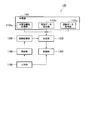
- FIG. 2 is a schematic block diagram illustrating a software configuration of the water quality management device according to the first embodiment.
- the water quality management device 110 includes an acquisition unit 1101, a water quality index value acquisition unit 1101a, an environmental data acquisition unit 1101b, an operation data acquisition unit 1101c, a relationship storage unit 1102, a determination unit 1103, a control unit 1104, an input unit 1105, and an update unit 1106. Is provided.
- the acquisition unit 1101 acquires plant data related to 10 in the power plant. Specifically, the acquisition unit 1101 includes a water quality index value acquisition unit 1101a, an environmental data acquisition unit 1101b, and an operation data acquisition unit 1101c.
- the water quality index value acquisition unit 1101a acquires the water quality index value indicating the water quality from the circulating water quality sensor 1052, the makeup water quality sensor 1062, and the drainage quality sensor 1072 as plant data.
- the water quality index value acquisition unit 1101a acquires the circulating water quality index value from the circulating water quality sensor 1052.
- the water quality index value acquisition unit 1101 a acquires the makeup water quality index value from the makeup water quality sensor 1062.
- the water quality index value acquisition unit 1101a acquires the drainage quality index value from the drainage quality sensor 1072.
- the environmental data acquisition unit 1101b acquires environmental data (such as weather, temperature and humidity, and quality of makeup water) from the environment measurement device 111 as plant data.
- the operation data acquisition unit 1101c acquires operation data of the power plant 10 (output of the power plant 10, boiler temperature, pressure, and the like) from the operation monitoring device 112 as plant data.
- the relationship storage unit 1102 stores the relationship between the circulating water quality index value, the makeup water quality index value, the drainage quality index value, and the environmental data, and the target value of the cooling water concentration rate of the cooling water circulation line 105.
- the concentration rate is a value obtained by dividing the amount of makeup water by the amount of drainage.
- the relationship storage unit 1102 stores one or more inference rules. In the initial state, the relationship storage unit 1102 stores provisional inference rules determined in advance by an engineer. As an example of the format of the inference rule, “cooling when the circulating water quality index value is X1 or more and X2 or less, the makeup water quality index value Y1 or more and Y2 or less, and the wastewater quality index value is Z1 or more and Z2 or less.
- the target value of the water concentration ratio is T ”.
- variables used for inference rule conditions include water quality index values, rate of change of water quality index values, statistics of water quality index values, operating data, rate of change of operating data, statistics of operating data, environmental data, environmental data Rate of change, and environmental data statistics.
- the determination unit 1103 includes the water quality index value acquired by the water quality index value acquisition unit 1101a, the environmental data acquired by the environment data acquisition unit 1101b, the operation data acquired by the operation data acquisition unit 1101c, and the inference stored in the relationship storage unit 1102 Based on the rules, the target value of the cooling water concentration rate of the cooling water circulation line 105 is determined. Specifically, when a plurality of inference rules are stored in the relationship storage unit 1102, the determination unit 1103 obtains an inference result based on each inference rule, integrates the plurality of inference results, and cools the cooling water. Determine the target concentration factor. Therefore, the determination unit 1103 can increase the accuracy of the target value of the concentration factor.
- the determination unit 1103 may determine the target value by specifying one inference rule from the plurality of inference rules in addition to determining the target value from the plurality of inference rules.
- the determination unit 1103 is realized by an inference engine. That is, the relationship storage unit 1102 and the determination unit 1103 function as an expert system that is an example of artificial intelligence.
- the control unit 1104 outputs a control command to the fourth water supply pump 1061, the blow valve 1071, and the second chemical injection pump 1082 based on the target value of the cooling water concentration rate determined by the determination unit 1103.
- the concentration rate is a value obtained by dividing the amount of makeup water by the amount of drainage.
- the amount of drainage is specified by multiplying the ratio between the target value of the electrical conductivity of the cooling water and the actually measured value by the amount of makeup water. Therefore, the control unit 1104 can calculate the makeup water amount and the drainage amount based on the cooling water concentration ratio.
- the amount of chemical injection is an amount proportional to the amount of drainage. Therefore, the control unit 1104 can calculate the chemical injection amount based on the specified drainage amount.
- the input unit 1105 receives an input of a target value for the cooling water concentration rate from a skilled engineer.
- This target value is based on the water quality index value acquired by the skilled engineer by the water quality index value acquisition unit 1101a, the environmental data acquired by the environmental data acquisition unit 1101b, and the operation data acquired by the operation data acquisition unit 1101c. It is an appropriate target value specified by Skilled engineers should ensure that the cooling water quality index value does not exceed the prescribed wastewater regulation value, that the circulating water system does not deteriorate due to scale, slime, or corrosion, and that water management costs are reduced. Specify the target value of the concentration ratio.
- the water quality management cost increases as the amount of makeup water, the amount of drainage, and the amount of chemical injection increase.
- the input unit 1105 receives an input of the reason for reaching the target value from a skilled engineer.
- One example of the reason for reaching the target value is “because the circulating water quality index value is X1 or more and the makeup water quality index value is Y1 or more”. That is, the input unit 1105 can accept an input in the same format as the condition part of the inference rule as the reason for reaching the target value.
- the update unit 1106 generates an inference rule based on the concentration factor and reason input to the input unit 1105.
- the update unit 1106 stores the generated inference rule in the relationship storage unit 1102.
- FIG. 3 is a flowchart showing the operation of the water quality management device according to the first embodiment.
- the water quality management device 110 executes the following processing at regular intervals.
- the water quality index value acquisition unit 1101a acquires a water quality index value indicating the water quality from the circulating water quality sensor 1052, the makeup water quality sensor 1062, and the drainage quality sensor 1072.
- the environmental data acquisition unit 1101b acquires environmental data from the environmental measurement device 111.
- the driving data acquisition unit 1101c acquires environmental data from the driving monitoring device 112. That is, the water quality index value acquisition unit 1101a acquires the circulating water quality index value, the makeup water quality index value, and the drainage quality index value, the environmental data acquisition unit 1101b acquires the environmental data, and the operation data acquisition unit 1101c Data is acquired (step S1).
- the determination unit 1103 determines the target value of the cooling water concentration rate based on the inference rules stored in the relationship storage unit 1102 (step S2).
- the inference rule is that the target value determined by the determination unit 1103 is different from the judgment of the skilled engineer (the target value input by the skilled engineer) by the processing from step S3 to step S4 described later
- the engineer's judgment is sequentially updated as learning data. Therefore, in the water quality management device 110, learning of the determination unit 1103 proceeds, and the accuracy of the target value of the determined concentration ratio of the cooling water is increased.
- the update unit 1106 determines whether or not the input unit 1105 has received the target value of the concentration factor and the reason for reaching the target value from a skilled engineer. Determine (step S3).
- the control unit 1104 is based on the concentration factor target value determined by the determination unit 1103 in step S2.
- a makeup water amount, a drainage amount, and a chemical injection amount are calculated (step S4).
- the control unit 1104 controls the fourth water supply pump 1061, the blow valve 1071, and the second chemical injection pump 1082 based on the calculation result (step S5).
- control unit 1104 outputs a control command for replenishing the calculated amount of makeup water to the fourth feed water pump 1061.
- the control unit 1104 outputs a control command for draining the calculated drainage amount to the blow valve 1071.
- the control unit 1104 outputs a control command for injecting the calculated chemical injection amount to the second chemical injection pump 1082.
- step S3 when the concentration unit target value and the reason for reaching the target value are input to the input unit 1105 (step S3: YES), the update unit 1106 infers based on the target value and reason input to the input unit 1105. A rule is generated (step S6). Next, the update unit 1106 stores the generated inference rule in the relationship storage unit 1102 (step S7). In this way, since the inference rules stored in the relationship storage unit 1102 are sequentially updated based on the judgment of a skilled engineer, the learning of the determination unit 1103 proceeds and the accuracy of the target value of the cooling water concentration rate determined is determined. Will increase.
- the control unit 1104 calculates the control amount of the circulating water system, that is, the makeup water amount, the drainage amount, and the chemical injection amount, based on the target value of the cooling water concentration rate input to the input unit 1105 (step S8).
- the control unit 1104 controls the fourth water supply pump 1061, the blow valve 1071, and the second chemical injection pump 1082 based on the calculation result (step S9).
- the control unit 1104 outputs a control command for replenishing the calculated amount of makeup water to the fourth feed water pump 1061.
- the control unit 1104 outputs a control command for draining the calculated drainage amount to the blow valve 1071.
- the control unit 1104 outputs a control command for injecting the calculated chemical injection amount to the second chemical injection pump 1082.
- the water quality index value acquisition unit 1101a acquires the water quality index value including the makeup water quality index value indicating the quality of the makeup water and the circulating water quality index value indicating the quality of the circulating water.
- the determining unit determines the cooling water concentration rate of the circulating water system based on the water quality index value acquired by the water quality index value acquiring unit 1101a.
- the water quality management apparatus 110 can appropriately manage the quality of the circulating water system even when the quality of the makeup water is not constant.
- the relationship storage unit 1102 stores an inference rule indicating the relationship between the water quality index value and the concentration control amount.
- the determination unit 1103 determines the concentration factor based on the water quality index value acquired by the water quality index value acquisition unit 1101a and the relationship stored in the relationship storage unit 1102. In this manner, the relation storage unit 1102 stores the inference rules for obtaining the concentration ratio that satisfies the drainage regulations, does not cause deterioration of the circulating water system, and can suppress the water quality management cost.
- the management device 110 can appropriately manage the water treatment system 100.
- the input unit 1105 includes the cooling water for satisfying the predetermined limit value specified by the engineer (specialist or expert) based on the water quality index value acquired by the water quality index value acquisition unit 1101a. Accepts input of concentration factor.
- the predetermined limit value include a drainage regulation value, water quality leading to deterioration of the circulating water system, and water quality management cost.
- the update unit 1106 updates the relationship stored in the relationship storage unit 1102 based on the concentration factor input to the input unit 1105. As a result, inference rules for obtaining a concentration factor that satisfies a predetermined limit value are accumulated in the relationship storage unit 1102. Therefore, the water quality management device 110 can appropriately manage the water treatment system 100.
- the water quality management device 110 manages the water quality of the circulating water system constituted by the cooling water circulation line 105, the second supply line 106, the second drainage line 107, and the second chemical injection line 108.
- the water quality management device 110 according to the second embodiment has a water quality of a circulating water system constituted by the steam circulation line 101, the first supply line 102, the first drainage line 103, and the first chemical injection line 104. Manage.
- FIG. 4 is a schematic block diagram showing the configuration of the water treatment system according to the second embodiment.
- the water treatment system 100 according to the present embodiment is different from the first embodiment in the installation positions of the circulating water quality sensor 1052, the makeup water quality sensor 1062, and the drainage quality sensor 1072.
- the circulating water quality sensor 1052 is provided in the steam circulation line 101.
- the makeup water quality sensor 1062 is provided in the first makeup line 102.
- the drainage quality sensor 1072 is provided in the first drainage line 103.
- the water quality management device 110 is based on the water quality detected by the circulating water quality sensor 1052, the makeup water quality sensor 1062, and the waste water quality sensor 1072, the power of the second feed pump 1021, the amount of waste water in the boiler 11, and the first The power of the medicine injection pump 1042 is determined.
- the operation of the water quality management device 110 according to the present embodiment is the same as that of the first embodiment. Thereby, the water quality management apparatus 110 can appropriately manage the water quality of the circulating water system constituted by the steam circulation line 101, the first supply line 102, the first drainage line 103, and the first chemical injection line 104. .
- the determination unit 1103 of the water quality management device 110 calculates the concentration factor, but is not limited thereto.
- the determination unit 1103 according to another embodiment may calculate another concentration control amount related to the concentration factor. Examples of the concentration control amount include concentration rate, water supply amount, drainage amount, chemical injection amount, valve opening, and pump power.
- the input unit 1105 receives an input of the reason for reaching the target value in addition to the target value of the concentration rate of circulating water, but is not limited thereto.
- the input unit 1105 according to another embodiment may not receive an input of the reason for reaching the target value.
- the update unit 1106 is based on the target value of the concentration rate of circulating water input to the input unit 1105, the water quality index value acquired by the water quality index value acquisition unit 1101a, and the environmental data acquired by the environmental data acquisition unit 1101b. Update inference rules.
- the determination unit 1103 specifies one inference rule from a plurality of inference rules stored in the relationship storage unit 1102 and determines the enrichment control amount based on the specified inference rule. I can't.
- the determination unit 1103 may determine the concentration control amount based on an artificial intelligence technique other than the expert system.
- the determination unit 1103 may determine the concentration control amount by a determination method based on machine learning.
- the relationship storage unit 1102 stores a prediction model obtained by machine learning.
- the prediction model is an example of the relationship between the water quality index value and the concentration control amount.
- the update unit 1106 receives the target value of the concentration factor input to the input unit 1105, the water quality index value acquired by the water quality index value acquisition unit 1101a, the environmental data acquired by the environmental data acquisition unit 1101b, and the operation data acquisition unit 1101c.
- the prediction model stored in the relationship storage unit 1102 is updated using the combination of driving data as teacher data.
- the determination unit 1103 determines the target value of the concentration rate based on the circulating water quality index value, the makeup water quality index value, and the wastewater quality index value, but is not limited thereto.
- the determination unit 1103 according to another embodiment may determine the target value of the concentration factor without using the wastewater quality index value. This is because the circulating water quality index value and the drainage quality index value show almost the same value.
- the determination unit 1103 according to another embodiment may determine a target value for the concentration rate using another water quality index value in addition to the circulating water quality index value and the makeup water quality index value.
- the water quality management device 110 includes the control unit 1104 that controls the circulating water system, but is not limited thereto.
- the water quality management apparatus 110 may output the concentration rate determined by the determination unit 1103 to the outside and may not control the circulating water system.
- the water quality management device 110 may display the target value of the concentration rate determined by the determination unit 1103 or the control amount of the circulating water system on an external display device. In this case, the operator controls the circulating water system according to the displayed target value or control amount of the concentration ratio.
- FIG. 5 is a schematic block diagram illustrating a configuration of a computer according to at least one embodiment.
- the computer 900 includes a CPU 901, a main storage device 902, an auxiliary storage device 903, and an interface 904.
- the above-described water quality management device 110 is mounted on the computer 900.
- the operation of each processing unit described above is stored in the auxiliary storage device 903 in the form of a program.
- the CPU 901 reads a program from the auxiliary storage device 903, develops it in the main storage device 902, and executes the above processing according to the program.
- the CPU 901 ensures a storage area corresponding to the above-described relation storage unit 1102 in the main storage device 902 or the auxiliary storage device 903 according to the program.
- the auxiliary storage device 903 is an example of a computer-readable medium.
- Other examples of computer readable media include magnetic disks, magneto-optical disks, CD-ROMs, DVD-ROMs, semiconductor memory, and other tangible non-transitory media connected via interface 904. .
- this program is distributed to the computer 900 via a communication line, the computer 900 that has received the distribution may develop the program in the main storage device 902 and execute the above processing.
- the program may be for realizing a part of the functions described above.
- the program may be a so-called difference file (difference program) that realizes the above-described function in combination with another program already stored in the auxiliary storage device 903.
- At least a part of the above-described water quality management device 110 may be realized by a semiconductor circuit such as ASIC (Application Specific Integrated Circuit).
- ASIC Application Specific Integrated Circuit
- the water quality management device determines the concentration control amount based on the replenishment water quality index value indicating the quality of the makeup water in addition to the circulation water quality index value indicating the quality of the circulating water circulating in the circulation line. Thereby, the water quality management apparatus can appropriately manage the quality of the circulating water system even when the quality of the makeup water is not constant.
Landscapes
- Engineering & Computer Science (AREA)
- Water Supply & Treatment (AREA)
- Physics & Mathematics (AREA)
- Chemical & Material Sciences (AREA)
- Thermal Sciences (AREA)
- General Engineering & Computer Science (AREA)
- Mechanical Engineering (AREA)
- Organic Chemistry (AREA)
- Hydrology & Water Resources (AREA)
- Artificial Intelligence (AREA)
- Health & Medical Sciences (AREA)
- Environmental & Geological Engineering (AREA)
- Life Sciences & Earth Sciences (AREA)
- Medicinal Chemistry (AREA)
- General Physics & Mathematics (AREA)
- Automation & Control Theory (AREA)
- Evolutionary Computation (AREA)
- Computer Vision & Pattern Recognition (AREA)
- Software Systems (AREA)
- Medical Informatics (AREA)
- Testing And Monitoring For Control Systems (AREA)
- Preventing Corrosion Or Incrustation Of Metals (AREA)
- Control Of Non-Electrical Variables (AREA)
Abstract
補給水の水質を示す補給水質指標値および循環水の水質を示す循環水質指標値を含む水質指標値を取得する水質指標値取得部(1101a)と、水質指標値取得部(1101a)が取得した水質指標値に基づいて循環水系統の濃縮倍率に関する濃縮制御量を決定する決定部(1103)とを備える。
Description
本発明は、水質管理装置、水処理システム、水質管理方法、および水処理システムの最適化プログラムに関する。
火力発電所には、蒸気タービンから排気した蒸気を冷却するための冷却水を循環させる冷却水系統が設けられることがある。冷却水系統は、蒸気を冷却する復水器と、復水器で加熱された冷却水を冷却する冷却塔とを備える。冷却塔において、冷却水が大気中で蒸発するため、冷却水系統には、常に補給水を補給する必要がある。補給水には、冷却水系統の劣化の原因となる物質が含まれ得る。劣化の原因となる物質の例としては、腐食および蒸発残渣となりうる塩分、およびスケールの原因となり得るシリカが挙げられる。冷却水系統を劣化させないために、一定量の冷却水が排出され、また一定量の薬剤が注入される。
特許文献1には、補給水量に連動して薬剤注入制御を行う方法として、循環している冷却水の電気伝導率が設定値より高いときにブロー(排出)を行って補給水を注入し、冷却水の電気伝導率が設定値より低いときにブローを停止する方法が開示されている。
しかしながら、補給水の水質が一定でない場合、特許文献1に開示された方法では、適切に冷却水系統の水質を管理することができない可能性がある。例えば、地下水または地表水から取水される原水は、水質が変動することが知られている。そのため、原水を補給水とする場合、補給水の水質が最も悪い状態を基準に冷却水の濃縮倍率の目標値を定め、制御する必要がある。補給水の水質を規定する変数は、複数ある。複数の変数の組み合わせにより濃縮倍率の目標値が変化する。原水の水質が変化しても冷却水の濃縮倍率の目標値が変えない場合、より高い濃縮倍率での運用が可能であるにも関わらず、低い濃縮倍率で水質の管理がなされる。そのため、冷却水系統へ薬剤が必要以上に注入され、水質管理コストを抑えることができない可能性がある。
長期間の運転において電気伝導率計に誤差が生じ、校正を頻繁に行わなければ正しい値を把握することが困難であり、電気伝導率でブロー量を規定する従来制御方式では技術的な課題も存在する。
本発明の目的は、補給水の水質が一定でない場合にも適切に循環水系統の水質を管理する水質管理装置、水処理システム、水質管理方法、および水処理システムの最適化プログラムを提供することにある。
長期間の運転において電気伝導率計に誤差が生じ、校正を頻繁に行わなければ正しい値を把握することが困難であり、電気伝導率でブロー量を規定する従来制御方式では技術的な課題も存在する。
本発明の目的は、補給水の水質が一定でない場合にも適切に循環水系統の水質を管理する水質管理装置、水処理システム、水質管理方法、および水処理システムの最適化プログラムを提供することにある。
本発明の第1の態様によれば、水質管理装置は、循環水が循環する循環ラインと、前記循環ラインに補給水を供給する補給ラインと、前記循環ラインから前記循環水を排出する排出ラインと、前記循環ラインに薬剤を注入する薬注ラインとを備えるプラントの循環水系統を管理する水質管理装置であって、前記循環水系統の濃縮倍率に関する濃縮制御量を決定する決定部と、前記決定部により前記濃縮制御量の決定に用いる前記プラントに関するプラントデータを取得する取得部と、前記プラントデータの条件と当該条件を満たす場合における濃縮制御量とを関連付けた推論規則を記憶する関係記憶部と、前記取得部が取得した前記プラントデータに基づいて特定した、所定の制限値を満たすための濃縮制御量の入力を受け付ける入力部と、前記入力部に入力された前記濃縮制御量に基づいて新たな推論規則を生成し、当該新たな推論規則を前記関係記憶部に記録する更新部とを備え、前記決定部は、前記取得部が取得した前記プラントデータと前記関係記憶部が記憶する前記推論規則とに基づいて濃縮制御量を決定する。
本発明の第2の態様によれば、第1の態様に係る水質管理装置は、前記プラントデータと前記濃縮制御量との関係を記憶する関係記憶部をさらに備え、前記決定部は、前記取得部が取得した前記プラントデータと前記関係記憶部が記憶する前記関係とに基づいて濃縮制御量を決定するものであってよい。
本発明の第3の態様によれば、第1または第2の態様に係る水質管理装置は、前記決定部が決定した前記濃縮制御量に基づいて、前記補給ラインに供給させる前記補給水の量、前記排出ラインから排出させる前記循環水の量、および前記循環ラインに注入させる前記薬剤の量のうち少なくとも1つを制御する制御部をさらに備えるものであってよい。
本発明の第4の態様によれば、第1の態様に係る水質管理装置は、前記取得部は、前記補給水の水質を示す補給水質指標値および前記循環水の水質を示す循環水質指標値を含む水質指標値を取得する水質指標値取得部を有し、前記決定部は、前記水質指標値取得部が取得した前記水質指標値に基づいて前記濃縮制御量を決定するものであってよい。
本発明の第5の態様によれば、第4の態様に係る水質管理装置は、前記水質指標値が、前記排出ラインから排出される前記循環水の水質を示す排出水質指標値を含むものであってよい。
本発明の第6の態様によれば、第1の態様に係る水質管理装置は、前記取得部は、プラントの環境データを取得する環境データ取得部を有し、前記決定部は、前記環境データ取得部が取得した前記環境データに基づいて前記濃縮制御量を決定するものであってよい。
本発明の第7の態様によれば、第1の態様に係る水質管理装置は、前記取得部は、プラントの運転データを取得する運転データ取得部を有し、前記決定部は、前記運転データ取得部が取得した前記運転データに基づいて前記濃縮制御量を決定するものであってよい。
本発明の第8の態様によれば、水処理システムは、循環水が循環する循環ラインと、前記循環ラインに補給水を供給する補給ラインと、前記循環ラインから前記循環水を排出する排出ラインと、前記循環ラインに薬剤を注入する薬注ラインとを備える循環水系統と、第1から第7の何れかの態様に係る水質管理装置とを備える。
本発明の第9の態様によれば、水質管理方法は、循環水が循環する循環ラインと、前記循環ラインに補給水を供給する補給ラインと、前記循環ラインから前記循環水を排出する排出ラインと、前記循環ラインに薬剤を注入する薬注ラインとを備えるプラントの循環水系統の水質管理方法であって、前記プラントに関するプラントデータを取得する取得ステップと、取得した前記プラントデータに基づいて特定した、所定の制限値を満たすための濃縮制御量の入力を受け付ける入力ステップと、入力された前記濃縮制御量に基づいて新たな推論規則を生成し、当該新たな推論規則を、前記プラントデータの条件と当該条件を満たす場合における濃縮制御量とを関連付けた推論規則を記憶する関係記憶部に記録する更新ステップと、前記取得ステップで取得した前記プラントデータと前記関係記憶部が記憶する前記推論規則とに基づいて濃縮制御量を決定する決定ステップと、を有する。
本発明の第10の態様によれば、水処理システムの最適化プログラムは、循環水が循環する循環ラインと、前記循環ラインに補給水を供給する補給ラインと、前記循環ラインから前記循環水を排出する排出ラインと、前記循環ラインに薬剤を注入する薬注ラインとを備えるプラントの循環水系統を管理する水質管理装置のコンピュータを、前記プラントに関するプラントデータを取得する取得部、前記取得部が取得した前記プラントデータに基づいて濃縮制御量を決定する決定部、前記プラントデータの条件と当該条件を満たす場合における濃縮制御量とを関連付けた推論規則を記憶する関係記憶部、前記取得部が取得した前記プラントデータに基づいて特定した、所定の制限値を満たすための濃縮制御量の入力を受け付ける入力部、前記入力部に入力された前記濃縮制御量に基づいて新たな推論規則を生成し、当該新たな推論規則を前記関係記憶部に記録する更新部として機能させ、前記決定部は、前記取得部が取得した前記プラントデータと前記関係記憶部が記憶する前記推論規則とに基づいて濃縮制御量を決定する。
上記態様のうち少なくとも1つの態様によれば、水質管理装置は、循環ラインを循環する循環水の水質を示す循環水質指標値に加え、補給水の水質を示す補給水質指標値に基づいて濃縮制御量を決定する。これにより、水質管理装置は、補給水の水質が一定でない場合にも適切に循環水系統の水質を管理することができる。
《第1の実施形態》
以下、図面を参照しながら実施形態について詳しく説明する。
図1は、第1の実施形態に係る水処理システムの構成を示す概略ブロック図である。
本実施形態に係る水処理システム100は、発電プラント10に設けられる。発電プラント10は、ボイラ11、蒸気タービン12、発電機13、復水器14、純水装置15、および冷却塔16を備える。
ボイラ11は、水を蒸発させて蒸気を発生させる。蒸気タービン12は、ボイラ11が発生させた蒸気により回転する。発電機13は、蒸気タービン12の回転エネルギーを電力に変換する。復水器14は、蒸気タービン12から排出される蒸気と冷却水とを熱交換させ、蒸気を水に戻す。純水装置15は、純水を生成する。冷却塔16は、復水器14で熱交換された冷却水を冷却する。冷却塔16には、冷却水を冷却するためのファン(図示せず)が設けられる。当該ファンはインバータ制御または運転するファンの台数制御により回転数を制御可能に構成される。
以下、図面を参照しながら実施形態について詳しく説明する。
図1は、第1の実施形態に係る水処理システムの構成を示す概略ブロック図である。
本実施形態に係る水処理システム100は、発電プラント10に設けられる。発電プラント10は、ボイラ11、蒸気タービン12、発電機13、復水器14、純水装置15、および冷却塔16を備える。
ボイラ11は、水を蒸発させて蒸気を発生させる。蒸気タービン12は、ボイラ11が発生させた蒸気により回転する。発電機13は、蒸気タービン12の回転エネルギーを電力に変換する。復水器14は、蒸気タービン12から排出される蒸気と冷却水とを熱交換させ、蒸気を水に戻す。純水装置15は、純水を生成する。冷却塔16は、復水器14で熱交換された冷却水を冷却する。冷却塔16には、冷却水を冷却するためのファン(図示せず)が設けられる。当該ファンはインバータ制御または運転するファンの台数制御により回転数を制御可能に構成される。
水処理システム100は、蒸気循環ライン101、第1補給ライン102、第1排水ライン103、第1薬注ライン104、冷却水循環ライン105、第2補給ライン106、第2排水ライン107、第2薬注ライン108、排水処理装置109、水質管理装置110、および環境測定装置111を備える。
蒸気循環ライン101は、蒸気タービン12、復水器14、およびボイラ11に水および蒸気を循環させるラインである。蒸気循環ライン101のうち復水器14とボイラ11との間には、第1給水ポンプ1011が設けられる。第1給水ポンプ1011は、復水器14からボイラ11へ向けて水を圧送する。
第1補給ライン102は、純水装置15が生成する純水を蒸気循環ライン101に供給するためのラインである。第1補給ライン102には、第2給水ポンプ1021が設けられる。第2給水ポンプ1021は、復水器14への水張り時に使用される。運転中において第1補給ライン102内の水は、復水器14の減圧により純水装置15から復水器14へ向けて圧送される。
第1補給ライン102は、純水装置15が生成する純水を蒸気循環ライン101に供給するためのラインである。第1補給ライン102には、第2給水ポンプ1021が設けられる。第2給水ポンプ1021は、復水器14への水張り時に使用される。運転中において第1補給ライン102内の水は、復水器14の減圧により純水装置15から復水器14へ向けて圧送される。
第1排水ライン103は、蒸気循環ライン101を循環する水の一部を、ボイラ11から排水処理装置109へ排出するためのラインである。
第1薬注ライン104は、蒸気循環ライン101にpH調整剤、脱酸素剤、またはその他の薬剤を供給するためのラインである。第1薬注ライン104は、薬剤を貯留する第1薬注タンク1041と、第1薬注タンク1041から蒸気循環ライン101へ薬剤を供給する第1薬注ポンプ1042とを備える。
蒸気循環ライン101、第1補給ライン102、第1排水ライン103、および第1薬注ライン104によって循環水系統が構成される。
第1薬注ライン104は、蒸気循環ライン101にpH調整剤、脱酸素剤、またはその他の薬剤を供給するためのラインである。第1薬注ライン104は、薬剤を貯留する第1薬注タンク1041と、第1薬注タンク1041から蒸気循環ライン101へ薬剤を供給する第1薬注ポンプ1042とを備える。
蒸気循環ライン101、第1補給ライン102、第1排水ライン103、および第1薬注ライン104によって循環水系統が構成される。
冷却水循環ライン105は、復水器14および冷却塔16に冷却水を循環させるラインである。冷却水循環ライン105には、第3給水ポンプ1051および循環水質センサ1052が設けられる。第3給水ポンプ1051は、冷却塔16から復水器14へ向けて冷却水を圧送する。循環水質センサ1052は、冷却水循環ライン105を循環する冷却水の水質を検出する。センサによって検出される水質の例としては、電気伝導率、pH値、塩濃度、金属濃度、COD(Chemical Oxygen Demand)、BOD(Biochemical Oxygen Demand)、およびシリカ濃度、ならびにこれらの組み合わせが挙げられる。循環水質センサ1052は、検出した水質を示す循環水質指標値を水質管理装置110に出力する。
第2補給ライン106は、水源から取水される原水を、補給水として冷却水循環ライン105に供給するためのラインである。第2補給ライン106には、第4給水ポンプ1061および補給水質センサ1062が設けられる。第4給水ポンプ1061は、水源から冷却塔16へ向けて補給水を圧送する。補給水質センサ1062は、検出した水質を示す補給水質指標値を水質管理装置110に出力する。
第2排水ライン107は、冷却水循環ライン105を循環する水の一部を排水処理装置109へ排出するためのラインである。第2排水ライン107には、ブロー弁1071および排水質センサ1072が設けられる。ブロー弁1071は、冷却水循環ライン105から排水処理装置109へブローする排水の量を制限する。排水質センサ1072は、第2排水ライン107から排出される排水の水質を検出する。排水質センサ1072は、検出した水質を示す排水質指標値を水質管理装置110に出力する。
第2排水ライン107は、冷却水循環ライン105を循環する水の一部を排水処理装置109へ排出するためのラインである。第2排水ライン107には、ブロー弁1071および排水質センサ1072が設けられる。ブロー弁1071は、冷却水循環ライン105から排水処理装置109へブローする排水の量を制限する。排水質センサ1072は、第2排水ライン107から排出される排水の水質を検出する。排水質センサ1072は、検出した水質を示す排水質指標値を水質管理装置110に出力する。
第2薬注ライン108は、冷却水循環ライン105に防食材、防スケール財、スライムコントロール材、pH調整剤、またはその他の薬剤を供給するためのラインである。第2薬注ライン108は、薬剤を貯留する第2薬注タンク1081と、第2薬注タンク1081から冷却水循環ライン105へ薬剤を供給する第2薬注ポンプ1082とを備える。
冷却水循環ライン105、第2補給ライン106、第2排水ライン107、第2薬注ライン108によって循環水系統が構成される。
冷却水循環ライン105、第2補給ライン106、第2排水ライン107、第2薬注ライン108によって循環水系統が構成される。
排水処理装置109は、第1排水ライン103および第2排水ライン107から排出された排水に、酸、アルカリ、凝集剤、またはその他の薬剤を注入する。排水処理装置109は、薬剤により処理された排水を廃棄する。
水質管理装置110は、循環水質センサ1052が検出した水質、補給水質センサ1062が検出した水質、排水質センサ1072が検出した水質、および環境測定装置111が測定する発電プラント10周辺の環境データに基づいて、第4給水ポンプ1061の動力、ブロー弁1071の開度、および第2薬注ポンプ1082の注入量(プランジャのストローク量またはストローク数)を決定する。
水質管理装置110は、循環水質センサ1052が検出した水質、補給水質センサ1062が検出した水質、排水質センサ1072が検出した水質、および環境測定装置111が測定する発電プラント10周辺の環境データに基づいて、第4給水ポンプ1061の動力、ブロー弁1071の開度、および第2薬注ポンプ1082の注入量(プランジャのストローク量またはストローク数)を決定する。
環境測定装置111は、発電プラント10の周辺の環境を測定し、環境データを生成する。環境データの例としては、発電プラント10の周辺地域の天候、気温および湿度、ならびに補給水の水質(濁りレベルなど)が挙げられる。
運転監視装置112は、発電プラント10の運転データを測定し、運転データを生成する。運転データの例としては、発電プラント10の出力、各種(蒸気、水、冷却水、薬品など)流量、ボイラの温度や圧力、冷却水温度、冷却塔の風量などが挙げられる。
運転監視装置112は、発電プラント10の運転データを測定し、運転データを生成する。運転データの例としては、発電プラント10の出力、各種(蒸気、水、冷却水、薬品など)流量、ボイラの温度や圧力、冷却水温度、冷却塔の風量などが挙げられる。
図2は、第1の実施形態に係る水質管理装置のソフトウェア構成を示す概略ブロック図である。
水質管理装置110は、取得部1101、水質指標値取得部1101a、環境データ取得部1101b、運転データ取得部1101c、関係記憶部1102、決定部1103、制御部1104、入力部1105、および更新部1106を備える。
水質管理装置110は、取得部1101、水質指標値取得部1101a、環境データ取得部1101b、運転データ取得部1101c、関係記憶部1102、決定部1103、制御部1104、入力部1105、および更新部1106を備える。
取得部1101は、発電プラントに10に関するプラントデータを取得する。具体的には、取得部1101は、水質指標値取得部1101a、環境データ取得部1101bおよび運転データ取得部1101cを有する。
水質指標値取得部1101aは、循環水質センサ1052、補給水質センサ1062、および排水質センサ1072から水質を示す水質指標値をプラントデータとして取得する。水質指標値取得部1101aは、循環水質センサ1052から循環水質指標値を取得する。水質指標値取得部1101aは、補給水質センサ1062から補給水質指標値を取得する。水質指標値取得部1101aは、排水質センサ1072から排水質指標値を取得する。
環境データ取得部1101bは、環境測定装置111から発電プラント10周辺の環境データ(天候、気温および湿度、補給水の水質など)をプラントデータとして取得する。
運転データ取得部1101cは、運転監視装置112から発電プラント10の運転データ(発電プラント10の出力、ボイラの温度や圧力など)をプラントデータとして取得する。
水質指標値取得部1101aは、循環水質センサ1052、補給水質センサ1062、および排水質センサ1072から水質を示す水質指標値をプラントデータとして取得する。水質指標値取得部1101aは、循環水質センサ1052から循環水質指標値を取得する。水質指標値取得部1101aは、補給水質センサ1062から補給水質指標値を取得する。水質指標値取得部1101aは、排水質センサ1072から排水質指標値を取得する。
環境データ取得部1101bは、環境測定装置111から発電プラント10周辺の環境データ(天候、気温および湿度、補給水の水質など)をプラントデータとして取得する。
運転データ取得部1101cは、運転監視装置112から発電プラント10の運転データ(発電プラント10の出力、ボイラの温度や圧力など)をプラントデータとして取得する。
関係記憶部1102は、循環水質指標値、補給水質指標値、排水質指標値、および環境データと、冷却水循環ライン105の冷却水の濃縮倍率の目標値との関係を記憶する。濃縮倍率は、補給水量を排水量で除算して得られる値である。関係記憶部1102は、1または複数の推論規則を記憶する。関係記憶部1102には、初期状態において、予め技術者が決定した暫定的な推論規則を記憶させておく。推論規則の形式の例としては、「循環水質指標値がX1以上X2以下であり、かつ補給水質指標値Y1以上Y2以下であり、かつ排水質指標値がZ1以上Z2以下である場合に、冷却水の濃縮倍率の目標値はTである」という形式が挙げられる。推論規則の条件に用いる変数の例としては、水質指標値、水質指標値の変化率、水質指標値の統計量、運転データ、運転データの変化率、運転データの統計量、環境データ、環境データの変化率、および環境データの統計量が挙げられる。
決定部1103は、水質指標値取得部1101aが取得した水質指標値、環境データ取得部1101bが取得した環境データ、運転データ取得部1101cが取得した運転データ、および関係記憶部1102に記憶された推論規則に基づいて、冷却水循環ライン105の冷却水の濃縮倍率の目標値を決定する。具体的には、決定部1103は、関係記憶部1102に複数の推論規則が記憶されている場合、それぞれの推論規則に基づいて推論結果を求め、この複数の推論結果を統合して冷却水の濃縮倍率の目標値を決定する。したがって、決定部1103は、濃縮倍率の目標値の確度を高めることができる。推論規則の例としては、ニューラルネットワーク、ベイジアンネットワーク、サポートベクタマシン、および事例ベース推論が挙げられる。決定部1103は、複数の推論規則から目標値を決定する他に、複数の推論規則の中から1つの推論規則を特定して目標値を決定するようにしてもよい。決定部1103は、推論エンジンによって実現される。つまり、関係記憶部1102と決定部1103は、人工知能の一例であるエキスパートシステムとして機能する。
制御部1104は、決定部1103が決定した冷却水の濃縮倍率の目標値に基づいて、第4給水ポンプ1061、ブロー弁1071、および第2薬注ポンプ1082に制御命令を出力する。濃縮倍率は、補給水量を排水量で除算して得られる値である。排水量は、冷却水の電気伝導率の目標値と実測値の比に補給水量を乗算することで特定される。したがって、制御部1104は、冷却水の濃縮倍率に基づいて補給水量および排水量を算出することができる。また薬注量は、排水量に比例する量である。したがって、制御部1104は、特定した排水量に基づいて薬注量を算出することができる。
入力部1105は、熟練された技術者から冷却水の濃縮倍率の目標値の入力を受け付ける。この目標値は、熟練された技術者が水質指標値取得部1101aにより取得された水質指標値、環境データ取得部1101bより取得された環境データ、運転データ取得部1101cより取得された運転データに基づいて特定した適切な目標値である。熟練された技術者は、排水質指標値が所定の排水規制値を超えず、かつ循環水系統にスケール、スライム、または腐食による劣化が生じず、かつ水質管理コストを低減するように、冷却水の濃縮倍率の目標値を特定する。水質管理コストは、補給水量、排水量および薬注量が多いほど高くなる。このとき、入力部1105は、熟練された技術者から、目標値に至った理由の入力を受け付ける。目標値に至った理由の一例としては、「循環水質指標値がX1以上であり、かつ補給水質指標値がY1以上だから」という形式が挙げられる。つまり、入力部1105は、目標値に至った理由として推論規則の条件部と同様の形式の入力を受け付けることができる。
更新部1106は、入力部1105に入力された濃縮倍率と理由とに基づいて推論規則を生成する。更新部1106は、生成した推論規則を関係記憶部1102に記憶する。
更新部1106は、入力部1105に入力された濃縮倍率と理由とに基づいて推論規則を生成する。更新部1106は、生成した推論規則を関係記憶部1102に記憶する。
次に、本実施形態に係る水質管理装置110の動作について説明する。
図3は、第1の実施形態に係る水質管理装置の動作を示すフローチャートである。
水質管理装置110が起動すると、水質管理装置110は、以下に示す処理を一定時間ごとに実行する。
図3は、第1の実施形態に係る水質管理装置の動作を示すフローチャートである。
水質管理装置110が起動すると、水質管理装置110は、以下に示す処理を一定時間ごとに実行する。
水質指標値取得部1101aは、循環水質センサ1052、補給水質センサ1062、および排水質センサ1072から水質を示す水質指標値を取得する。環境データ取得部1101bは、環境測定装置111から環境データを取得する。同様に、運転データ取得部1101cは、運転監視装置112から環境データを取得する。つまり、水質指標値取得部1101aは、循環水質指標値、補給水質指標値、および排水質指標値を取得し、環境データ取得部1101bは、環境データを取得し、運転データ取得部1101cは、運転データを取得する(ステップS1)。
次に、決定部1103は、関係記憶部1102に記憶された推論規則に基づいて、冷却水の濃縮倍率の目標値を決定する(ステップS2)。ここで、推論規則は、後述するステップS3からステップS4の処理により、決定部1103により決定された目標値が熟練された技術者の判断(熟練された技術者が入力した目標値)と異なる場合、この技術者の判断(入力した目標値)を学習用のデータとして逐次更新される。したがって、水質管理装置110は、決定部1103の学習が進み、決定される冷却水の濃縮倍率の目標値の精度が高まる。
ステップS2で決定部1103が濃縮倍率の目標値を決定すると、更新部1106は、入力部1105に熟練された技術者から濃縮倍率の目標値および目標値に至った理由が入力されたか否かを判定する(ステップS3)。入力部1105に濃縮倍率の目標値および目標値に至った理由が入力されない場合(ステップS3:NO)、制御部1104は、ステップS2で決定部1103が決定した濃縮倍率の目標値に基づいて、補給水量、排水量および薬注量を算出する(ステップS4)。次に、制御部1104は、算出結果に基づいて第4給水ポンプ1061、ブロー弁1071、および第2薬注ポンプ1082を制御する(ステップS5)。具体的には、制御部1104は、算出した補給水量を補給させる制御命令を第4給水ポンプ1061に出力する。制御部1104は、算出した排水量を排水させる制御命令をブロー弁1071に出力する。制御部1104は、算出した薬注量を注入させる制御命令を第2薬注ポンプ1082に出力する。
他方、入力部1105に濃縮倍率の目標値および目標値に至った理由が入力された場合(ステップS3:YES)、更新部1106は、入力部1105に入力された目標値および理由に基づいて推論規則を生成する(ステップS6)。次に、更新部1106は、生成した推論規則を関係記憶部1102に記憶する(ステップS7)。このように、関係記憶部1102が記憶する推論規則は、熟練された技術者の判断により逐次更新されるため、決定部1103の学習が進み、決定される冷却水の濃縮倍率の目標値の精度が高まる。制御部1104は、入力部1105に入力された冷却水の濃縮倍率の目標値に基づいて循環水系統の制御量、すなわち補給水量、排水量および薬注量を算出する(ステップS8)。次に、制御部1104は、算出結果に基づいて第4給水ポンプ1061、ブロー弁1071、および第2薬注ポンプ1082を制御する(ステップS9)。具体的には、制御部1104は、算出した補給水量を補給させる制御命令を第4給水ポンプ1061に出力する。制御部1104は、算出した排水量を排水させる制御命令をブロー弁1071に出力する。制御部1104は、算出した薬注量を注入させる制御命令を第2薬注ポンプ1082に出力する。
このように、本実施形態によれば、水質指標値取得部1101aは、補給水の水質を示す補給水質指標値および循環水の水質を示す循環水質指標値を含む水質指標値を取得する。決定部は、水質指標値取得部1101aが取得した水質指標値に基づいて循環水系統の冷却水の濃縮倍率を決定する。これにより、水質管理装置110は、補給水の水質が一定でない場合にも適切に循環水系統の水質を管理することができる。
本実施形態によれば、関係記憶部1102は、水質指標値と濃縮制御量との関係を示す推論規則を記憶する。決定部1103は、水質指標値取得部1101aが取得した水質指標値と関係記憶部1102が記憶する関係とに基づいて濃縮倍率を決定する。このように、関係記憶部1102に、排水規制を満たし、循環水系統の劣化が生じず、かつ水質管理コストを抑えることができる濃縮倍率を求めるための推論規則を記憶しておくことで、水質管理装置110は、水処理システム100を適切に管理することができる。
本実施形態によれば、入力部1105は、水質指標値取得部1101aが取得した水質指標値に基づいて技術者(専門技術者またはエキスパート)が特定した所定の制限値を満たすための冷却水の濃縮倍率の入力を受け付ける。所定の制限値の例としては、排水規制値、循環水系統の劣化に至る水質、水質管理コストが挙げられる。更新部1106は、入力部1105に入力された濃縮倍率に基づいて関係記憶部1102が記憶する関係を更新する。これにより、所定の制限値を満たす濃縮倍率を求めるための推論規則が、関係記憶部1102に蓄積される。したがって、水質管理装置110は、水処理システム100を適切に管理することができる。
《第2の実施形態》
第1の実施形態に係る水質管理装置110は、冷却水循環ライン105、第2補給ライン106、第2排水ライン107、第2薬注ライン108によって構成される循環水系統の水質を管理する。これに対し、第2の実施形態に係る水質管理装置110は、蒸気循環ライン101、第1補給ライン102、第1排水ライン103、および第1薬注ライン104によって構成される循環水系統の水質を管理する。
第1の実施形態に係る水質管理装置110は、冷却水循環ライン105、第2補給ライン106、第2排水ライン107、第2薬注ライン108によって構成される循環水系統の水質を管理する。これに対し、第2の実施形態に係る水質管理装置110は、蒸気循環ライン101、第1補給ライン102、第1排水ライン103、および第1薬注ライン104によって構成される循環水系統の水質を管理する。
図4は、第2の実施形態に係る水処理システムの構成を示す概略ブロック図である。
本実施形態に係る水処理システム100は、循環水質センサ1052、補給水質センサ1062、および排水質センサ1072の設置位置が第1の実施形態と異なる。循環水質センサ1052は、蒸気循環ライン101に設けられる。補給水質センサ1062は、第1補給ライン102に設けられる。排水質センサ1072は、第1排水ライン103に設けられる。本実施形態に係る水質管理装置110は、循環水質センサ1052、補給水質センサ1062、および排水質センサ1072が検出した水質に基づいて、第2給水ポンプ1021の動力、ボイラ11における排水量、および第1薬注ポンプ1042の動力を決定する。本実施形態に係る水質管理装置110の動作は、第1の実施形態と同様である。
これにより、水質管理装置110は、蒸気循環ライン101、第1補給ライン102、第1排水ライン103、および第1薬注ライン104によって構成される循環水系統の水質を適切に管理することができる。
本実施形態に係る水処理システム100は、循環水質センサ1052、補給水質センサ1062、および排水質センサ1072の設置位置が第1の実施形態と異なる。循環水質センサ1052は、蒸気循環ライン101に設けられる。補給水質センサ1062は、第1補給ライン102に設けられる。排水質センサ1072は、第1排水ライン103に設けられる。本実施形態に係る水質管理装置110は、循環水質センサ1052、補給水質センサ1062、および排水質センサ1072が検出した水質に基づいて、第2給水ポンプ1021の動力、ボイラ11における排水量、および第1薬注ポンプ1042の動力を決定する。本実施形態に係る水質管理装置110の動作は、第1の実施形態と同様である。
これにより、水質管理装置110は、蒸気循環ライン101、第1補給ライン102、第1排水ライン103、および第1薬注ライン104によって構成される循環水系統の水質を適切に管理することができる。
《他の実施形態》
以上、図面を参照して一実施形態について詳しく説明してきたが、具体的な構成は上述のものに限られることはなく、様々な設計変更等をすることが可能である。
例えば、上述した実施形態に係る水質管理装置110の決定部1103は、濃縮倍率を算出するが、これに限られない。他の実施形態に係る決定部1103は、濃縮倍率に係る他の濃縮制御量を算出してもよい。濃縮制御量の例としては、濃縮倍率、給水量、排水量、薬注量、弁開度、およびポンプ動力が挙げられる。
以上、図面を参照して一実施形態について詳しく説明してきたが、具体的な構成は上述のものに限られることはなく、様々な設計変更等をすることが可能である。
例えば、上述した実施形態に係る水質管理装置110の決定部1103は、濃縮倍率を算出するが、これに限られない。他の実施形態に係る決定部1103は、濃縮倍率に係る他の濃縮制御量を算出してもよい。濃縮制御量の例としては、濃縮倍率、給水量、排水量、薬注量、弁開度、およびポンプ動力が挙げられる。
上述した実施形態に係る入力部1105は、循環水の濃縮倍率の目標値に加えて、当該目標値に至った理由の入力を受け付けるが、これに限られない。他の実施形態に係る入力部1105は、当該目標値に至った理由の入力を受け付けなくてもよい。この場合、更新部1106は、入力部1105に入力された循環水の濃縮倍率の目標値と水質指標値取得部1101aが取得した水質指標値、環境データ取得部1101bが取得した環境データに基づいて推論規則を更新する。
上述した実施形態に係る決定部1103は、関係記憶部1102が記憶する複数の推論規則から1つの推論規則を特定し、特定された推論規則に基づいて濃縮制御量を決定するが、これに限られない。他の実施形態に係る決定部1103は、エキスパートシステム以外の人工知能技術に基づいて濃縮制御量を決定してもよい。例えば、他の実施形態に係る決定部1103は、機械学習に基づく決定手法により濃縮制御量を決定してもよい。この場合、関係記憶部1102は、機械学習によって得られる予測モデルを記憶する。予測モデルは、水質指標値と濃縮制御量との関係の一例である。更新部1106は、入力部1105に入力された濃縮倍率の目標値、水質指標値取得部1101aが取得した水質指標値、環境データ取得部1101bが取得した環境データ、運転データ取得部1101cが取得した運転データの組み合わせを教師データとして、関係記憶部1102が記憶する予測モデルを更新する。
上述した実施形態に係る決定部1103は、循環水質指標値、補給水質指標値、および排水質指標値に基づいて濃縮倍率の目標値を決定するが、これに限られない。他の実施形態に係る決定部1103は、排水質指標値を用いずに濃縮倍率の目標値を決定してもよい。これは、循環水質指標値と排水質指標値とがほぼ同じ値を示すためである。また他の実施形態に係る決定部1103は、循環水質指標値および補給水質指標値に加えて、他の水質指標値を用いて濃縮倍率の目標値を決定してもよい。
上述した実施形態に係る水質管理装置110は、循環水系統を制御する制御部1104を備えるが、これに限られない。例えば、実施形態に係る水質管理装置110は、決定部1103が決定した濃縮倍率を外部へ出力し、循環水系統の制御を行わなくてもよい。例えば、水質管理装置110は、決定部1103が決定した濃縮倍率の目標値、または循環水系統の制御量を外部の表示装置に表示させてもよい。この場合、作業者は、表示された濃縮倍率の目標値または制御量に従って循環水系統を制御する。
図5は、少なくとも1つの実施形態に係るコンピュータの構成を示す概略ブロック図である。
コンピュータ900は、CPU901、主記憶装置902、補助記憶装置903、およびインタフェース904を備える。
上述の水質管理装置110は、コンピュータ900に実装される。上述した各処理部の動作は、プログラムの形式で補助記憶装置903に記憶されている。CPU901は、プログラムを補助記憶装置903から読み出して主記憶装置902に展開し、当該プログラムに従って上記処理を実行する。CPU901は、プログラムに従って、上述した関係記憶部1102に対応する記憶領域を主記憶装置902または補助記憶装置903に確保する。
コンピュータ900は、CPU901、主記憶装置902、補助記憶装置903、およびインタフェース904を備える。
上述の水質管理装置110は、コンピュータ900に実装される。上述した各処理部の動作は、プログラムの形式で補助記憶装置903に記憶されている。CPU901は、プログラムを補助記憶装置903から読み出して主記憶装置902に展開し、当該プログラムに従って上記処理を実行する。CPU901は、プログラムに従って、上述した関係記憶部1102に対応する記憶領域を主記憶装置902または補助記憶装置903に確保する。
少なくとも1つの実施形態において、補助記憶装置903は、コンピュータ読み取り可能な媒体の一例である。コンピュータ読み取り可能な媒体の他の例としては、インタフェース904を介して接続される磁気ディスク、光磁気ディスク、CD-ROM、DVD-ROM、半導体メモリ、およびその他の有形の一時的でない媒体が挙げられる。このプログラムが通信回線によってコンピュータ900に配信される場合、配信を受けたコンピュータ900が当該プログラムを主記憶装置902に展開し、上記処理を実行してもよい。
当該プログラムは、前述した機能の一部を実現するためのものであってもよい。当該プログラムは、前述した機能を補助記憶装置903に既に記憶されている他のプログラムとの組み合わせで実現するもの、いわゆる差分ファイル(差分プログラム)であってもよい。
上述の水質管理装置110の少なくとも一部は、ASIC(Application Specific Integrated Circuit)などの半導体回路によって実現されてもよい。
水質管理装置は、循環ラインを循環する循環水の水質を示す循環水質指標値に加え、補給水の水質を示す補給水質指標値に基づいて濃縮制御量を決定する。これにより、水質管理装置は、補給水の水質が一定でない場合にも適切に循環水系統の水質を管理することができる。
100 水処理システム
1011 第1給水ポンプ
1021 第2給水ポンプ
1051 第3給水ポンプ
1061 第4給水ポンプ
1042 第1薬注ポンプ
1082 第2薬注ポンプ
1071 ブロー弁
1052 循環水質センサ
1062 補給水質センサ
1072 排水質センサ
110 水質管理装置
1101 取得部
1101a 水質指標値取得部
1101b 環境データ取得部
1101c 運転データ取得部
1102 関係記憶部
1103 決定部
1104 制御部
1105 入力部
1106 更新部
111 環境測定装置
112 運転監視装置
1011 第1給水ポンプ
1021 第2給水ポンプ
1051 第3給水ポンプ
1061 第4給水ポンプ
1042 第1薬注ポンプ
1082 第2薬注ポンプ
1071 ブロー弁
1052 循環水質センサ
1062 補給水質センサ
1072 排水質センサ
110 水質管理装置
1101 取得部
1101a 水質指標値取得部
1101b 環境データ取得部
1101c 運転データ取得部
1102 関係記憶部
1103 決定部
1104 制御部
1105 入力部
1106 更新部
111 環境測定装置
112 運転監視装置
Claims (10)
- 循環水が循環する循環ラインと、前記循環ラインに補給水を供給する補給ラインと、前記循環ラインから前記循環水を排出する排出ラインと、前記循環ラインに薬剤を注入する薬注ラインとを備えるプラントの循環水系統を管理する水質管理装置であって、
前記循環水系統の濃縮倍率に関する濃縮制御量を決定する決定部と、
前記決定部により前記濃縮制御量の決定に用いる前記プラントに関するプラントデータを取得する取得部と、
前記プラントデータの条件と当該条件を満たす場合における濃縮制御量とを関連付けた1または複数の推論規則を記憶する関係記憶部と、
前記取得部が取得した前記プラントデータに基づいて特定した、所定の制限値を満たすための濃縮制御量の入力を受け付ける入力部と、
前記入力部に入力された前記濃縮制御量に基づいて新たな推論規則を生成し、当該新たな推論規則を前記関係記憶部に記録する更新部と
を備え、
前記決定部は、前記取得部が取得した前記プラントデータと前記関係記憶部が記憶する前記推論規則とに基づいて濃縮制御量を決定する
水質管理装置。 - 前記プラントデータと前記濃縮制御量との関係を記憶する関係記憶部をさらに備え、
前記決定部は、前記取得部が取得した前記プラントデータと前記関係記憶部が記憶する前記関係とに基づいて濃縮制御量を決定する
請求項1に記載の水質管理装置。 - 前記決定部が決定した前記濃縮制御量に基づいて、前記補給ラインに供給させる前記補給水の量、前記排出ラインから排出させる前記循環水の量、および前記循環ラインに注入させる前記薬剤の量のうち少なくとも1つを制御する制御部
をさらに備える請求項1または請求項2に記載の水質管理装置。 - 前記取得部は、前記補給水の水質を示す補給水質指標値および前記循環水の水質を示す循環水質指標値を含む水質指標値を取得する水質指標値取得部を有し、
前記決定部は、前記水質指標値取得部が取得した前記水質指標値に基づいて前記濃縮制御量を決定する
請求項1に記載の水質管理装置。 - 前記水質指標値が、前記排出ラインから排出される前記循環水の水質を示す排出水質指標値を含む
請求項4に記載の水質管理装置。 - 前記取得部は、プラントの環境データを取得する環境データ取得部を有し、
前記決定部は、前記環境データ取得部が取得した前記環境データに基づいて前記濃縮制御量を決定する
請求項1に記載の水質管理装置。 - 前記取得部は、プラントの運転データを取得する運転データ取得部を有し、
前記決定部は、前記運転データ取得部が取得した前記運転データに基づいて前記濃縮制御量を決定する
請求項1に記載の水質管理装置。 - 循環水が循環する循環ラインと、前記循環ラインに補給水を供給する補給ラインと、前記循環ラインから前記循環水を排出する排出ラインと、前記循環ラインに薬剤を注入する薬注ラインとを備える循環水系統と、
請求項1から請求項7の何れか1項に記載の水質管理装置と
を備える水処理システム。 - 循環水が循環する循環ラインと、前記循環ラインに補給水を供給する補給ラインと、前記循環ラインから前記循環水を排出する排出ラインと、前記循環ラインに薬剤を注入する薬注ラインとを備えるプラントの循環水系統の水質管理方法であって、
前記プラントに関するプラントデータを取得する取得ステップと、
取得した前記プラントデータに基づいて特定した、所定の制限値を満たすための濃縮制御量の入力を受け付ける入力ステップと、
入力された前記濃縮制御量に基づいて新たな推論規則を生成し、当該新たな推論規則を、前記プラントデータの条件と当該条件を満たす場合における濃縮制御量とを関連付けた1または複数の推論規則を記憶する関係記憶部に記録する更新ステップと、
前記取得ステップで取得した前記プラントデータと前記関係記憶部が記憶する前記推論規則とに基づいて濃縮制御量を決定する決定ステップと、
を有する水質管理方法。 - 循環水が循環する循環ラインと、前記循環ラインに補給水を供給する補給ラインと、前記循環ラインから前記循環水を排出する排出ラインと、前記循環ラインに薬剤を注入する薬注ラインとを備えるプラントの循環水系統を管理する水質管理装置のコンピュータを、
前記プラントに関するプラントデータを取得する取得部、
前記取得部が取得した前記プラントデータに基づいて濃縮制御量を決定する決定部、
前記プラントデータの条件と当該条件を満たす場合における濃縮制御量とを関連付けた1または複数の推論規則を記憶する関係記憶部、
前記取得部が取得した前記プラントデータに基づいて特定した、所定の制限値を満たすための濃縮制御量の入力を受け付ける入力部、
前記入力部に入力された前記濃縮制御量に基づいて新たな推論規則を生成し、当該新たな推論規則を前記関係記憶部に記録する更新部
として機能させ、
前記決定部は、前記取得部が取得した前記プラントデータと前記関係記憶部が記憶する前記推論規則とに基づいて濃縮制御量を決定する
水処理システムの最適化プログラム。
Priority Applications (3)
| Application Number | Priority Date | Filing Date | Title |
|---|---|---|---|
| CN201680053420.3A CN108027137B (zh) | 2015-09-18 | 2016-06-27 | 水质管理装置及方法、水处理系统及计算机可读取的介质 |
| US15/758,860 US10640392B2 (en) | 2015-09-18 | 2016-06-27 | Water quality management device, water treatment system, water quality management method, and program for optimizing water treatment system |
| EP16846066.5A EP3336425B1 (en) | 2015-09-18 | 2016-06-27 | Water quality management device, water treatment system, water quality management method, and water treatment system optimization program |
Applications Claiming Priority (2)
| Application Number | Priority Date | Filing Date | Title |
|---|---|---|---|
| JP2015-184964 | 2015-09-18 | ||
| JP2015184964A JP5925371B1 (ja) | 2015-09-18 | 2015-09-18 | 水質管理装置、水処理システム、水質管理方法、および水処理システムの最適化プログラム |
Publications (1)
| Publication Number | Publication Date |
|---|---|
| WO2017047193A1 true WO2017047193A1 (ja) | 2017-03-23 |
Family
ID=56069579
Family Applications (1)
| Application Number | Title | Priority Date | Filing Date |
|---|---|---|---|
| PCT/JP2016/068994 Ceased WO2017047193A1 (ja) | 2015-09-18 | 2016-06-27 | 水質管理装置、水処理システム、水質管理方法、および水処理システムの最適化プログラム |
Country Status (6)
| Country | Link |
|---|---|
| US (1) | US10640392B2 (ja) |
| EP (1) | EP3336425B1 (ja) |
| JP (1) | JP5925371B1 (ja) |
| CN (1) | CN108027137B (ja) |
| TW (1) | TWI608211B (ja) |
| WO (1) | WO2017047193A1 (ja) |
Cited By (2)
| Publication number | Priority date | Publication date | Assignee | Title |
|---|---|---|---|---|
| JP2022182596A (ja) * | 2021-05-28 | 2022-12-08 | 安川オートメーション・ドライブ株式会社 | データ処理装置、プログラム、及びデータ処理方法 |
| US12203145B2 (en) | 2017-03-15 | 2025-01-21 | The Broad Institute, Inc. | CRISPR effector system based diagnostics for virus detection |
Families Citing this family (24)
| Publication number | Priority date | Publication date | Assignee | Title |
|---|---|---|---|---|
| JP5925371B1 (ja) * | 2015-09-18 | 2016-05-25 | 三菱日立パワーシステムズ株式会社 | 水質管理装置、水処理システム、水質管理方法、および水処理システムの最適化プログラム |
| JP6763630B2 (ja) * | 2016-12-27 | 2020-09-30 | 三菱パワー株式会社 | プラント、循環水系統の水質管理システム及び循環水系統の水質管理方法 |
| JP6811688B2 (ja) * | 2017-06-30 | 2021-01-13 | 株式会社日立製作所 | 複数動作ユニット統合装置、およびその制御方法、並びに自律学習型ロボット装置 |
| JP6779185B2 (ja) * | 2017-08-25 | 2020-11-04 | 三菱パワー株式会社 | 水質制御装置、水処理システム、熱プラント、発電プラント、および水質制御方法 |
| JP2019084507A (ja) * | 2017-11-08 | 2019-06-06 | 栗田工業株式会社 | シリカスケールの成長抑制方法 |
| JP6676737B2 (ja) * | 2017-12-01 | 2020-04-08 | 三菱重工業株式会社 | 薬注制御装置、薬剤管理装置、水処理システム、薬注制御方法、およびプログラム |
| US20200109063A1 (en) * | 2017-12-01 | 2020-04-09 | Mitsubishi Heavy Industries, Ltd. | Chemical feed control device, water treatment system, chemical feed control method, and program |
| JP7263480B2 (ja) * | 2017-12-06 | 2023-04-24 | 三菱重工業株式会社 | 補機動力決定装置、プラント、補機動力決定方法、およびプログラム |
| CN108803318B (zh) * | 2018-05-25 | 2021-07-06 | 广州市合信方园工业设备有限公司 | 一种循环水除垢洁净机控制方法与系统 |
| JP6764486B2 (ja) * | 2018-07-26 | 2020-09-30 | 三菱電機株式会社 | 水処理プラント |
| CN109521813B (zh) * | 2018-11-13 | 2023-08-29 | 中国大唐集团科学技术研究院有限公司火力发电技术研究院 | 一种火力发电厂循环水浓缩倍率稳定控制的系统和方法 |
| JP7271205B2 (ja) * | 2019-01-29 | 2023-05-11 | 三菱重工業株式会社 | 発電プラントの水質監視システム、及びその水質監視方法並びに水質監視プログラム、発電プラント |
| JP7515237B2 (ja) * | 2019-03-08 | 2024-07-12 | 栗田工業株式会社 | 発電システム |
| CN110092507A (zh) * | 2019-05-30 | 2019-08-06 | 中国水利水电科学研究院 | 一种工业废水处理的方法及装置 |
| CN110186505B (zh) * | 2019-06-06 | 2020-02-14 | 浙江清华长三角研究院 | 一种基于支持向量机的农村生活污水处理设施出水达标情况的预测方法 |
| CN110426957B (zh) * | 2019-07-31 | 2020-03-13 | 深圳信息职业技术学院 | 一种基于时延观测器的水厂投药系统自适应滑模控制方法 |
| US12037262B2 (en) | 2020-01-29 | 2024-07-16 | Xylem Vue Inc. | Systems and methods relating to effective management of fluid infrastructure |
| JP7331737B2 (ja) * | 2020-03-06 | 2023-08-23 | 株式会社明電舎 | 水処理施設の運転支援装置 |
| JP7484578B2 (ja) * | 2020-08-28 | 2024-05-16 | 株式会社明電舎 | 水処理施設の運転支援装置及び運転支援方法 |
| CN112591887B (zh) * | 2020-11-03 | 2022-09-20 | 北京工业大学 | 一种基于核主成分分析和贝叶斯网络的污泥膨胀诊断方法 |
| CN113050534A (zh) * | 2021-03-15 | 2021-06-29 | 天津正达科技有限责任公司 | 一种用于循环冷却水系统的智慧控制系统及方法 |
| CN113652268B (zh) * | 2021-08-17 | 2022-08-30 | 新兴铸管股份有限公司 | 一种初冷器水循环系统及其控制方法 |
| CN114991258B (zh) * | 2022-06-14 | 2023-07-18 | 武汉钢铁有限公司 | 一种热轧水系统管网的节水管控方法及系统 |
| CN117065652B (zh) * | 2023-10-17 | 2024-01-05 | 山东格瑞水务有限公司 | 一种电厂循环水离子浓度调节装置 |
Citations (5)
| Publication number | Priority date | Publication date | Assignee | Title |
|---|---|---|---|---|
| JPS573875B2 (ja) * | 1977-11-29 | 1982-01-23 | ||
| JPH0756367B2 (ja) * | 1987-12-18 | 1995-06-14 | 株式会社荏原製作所 | ボイラ給水への薬液注入装置 |
| JP2001140086A (ja) * | 1999-11-12 | 2001-05-22 | Ebara Corp | ボイラ水循環系用腐蝕抑制剤及びボイラ水循環系の腐蝕抑制方法 |
| JP2008170112A (ja) * | 2007-01-12 | 2008-07-24 | Miura Co Ltd | 蒸気ボイラへの薬剤供給方法 |
| US20150251144A1 (en) * | 2012-09-28 | 2015-09-10 | Siemens Aktiengesellschaft | Method for recovering process wastewater from a steam power plant |
Family Cites Families (40)
| Publication number | Priority date | Publication date | Assignee | Title |
|---|---|---|---|---|
| DE2914145C3 (de) * | 1979-04-07 | 1982-02-04 | Hager & Elsässer GmbH, 7000 Stuttgart | Verfahren zur Verringerung des Brauchwasserbedarfs und Abwasseranfalls von thermischen Kraftwerken |
| JPS573875A (en) | 1980-06-11 | 1982-01-09 | Tamura Kaken Kk | Photopolymerizable ink composition |
| US4830757A (en) * | 1985-08-06 | 1989-05-16 | The Mogul Corporation | Telemetry system for water and energy monitoring |
| JP2533942B2 (ja) | 1989-03-13 | 1996-09-11 | 株式会社日立製作所 | 知識抽出方法およびプロセス運転支援システム |
| EP0390563A3 (en) * | 1989-03-31 | 1992-12-02 | Matsushita Electric Industrial Co., Ltd. | Fuzzy multi-stage inference apparatus |
| JPH0711297Y2 (ja) * | 1990-06-28 | 1995-03-15 | 三浦工業株式会社 | ボイラの薬注制御装置 |
| JP2583989Y2 (ja) * | 1990-07-31 | 1998-10-27 | 三浦工業株式会社 | 流動層式熱交換器 |
| US5342510A (en) * | 1992-02-03 | 1994-08-30 | H.E.R.C. Incorporated | Water control system using oxidation reduction potential sensing |
| US5855791A (en) * | 1996-02-29 | 1999-01-05 | Ashland Chemical Company | Performance-based control system |
| US5993194A (en) * | 1996-06-21 | 1999-11-30 | Lemelson; Jerome H. | Automatically optimized combustion control |
| US5822220A (en) * | 1996-09-03 | 1998-10-13 | Fisher-Rosemount Systems, Inc. | Process for controlling the efficiency of the causticizing process |
| US5895565A (en) * | 1996-10-04 | 1999-04-20 | Santa Barbara Control Systems | Integrated water treatment control system with probe failure detection |
| JPH1082503A (ja) * | 1997-08-09 | 1998-03-31 | Miura Co Ltd | ボイラの薬注制御方法 |
| US6633782B1 (en) * | 1999-02-22 | 2003-10-14 | Fisher-Rosemount Systems, Inc. | Diagnostic expert in a process control system |
| JP3679942B2 (ja) * | 1999-02-26 | 2005-08-03 | 株式会社東芝 | 処理水質制御装置 |
| US6535795B1 (en) * | 1999-08-09 | 2003-03-18 | Baker Hughes Incorporated | Method for chemical addition utilizing adaptive optimization |
| JP3116042B1 (ja) * | 1999-10-12 | 2000-12-11 | 東西化学産業株式会社 | 液体循環系設備 |
| US6468069B2 (en) * | 1999-10-25 | 2002-10-22 | Jerome H. Lemelson | Automatically optimized combustion control |
| JP4300337B2 (ja) * | 2000-06-15 | 2009-07-22 | 三浦工業株式会社 | 復水処理剤の注入量の制御方法 |
| US6716359B1 (en) * | 2000-08-29 | 2004-04-06 | United States Filter Corporation | Enhanced time-based proportional control |
| JP2003130587A (ja) * | 2001-10-29 | 2003-05-08 | Ebara Corp | 冷却水の循環冷却装置及びその水質管理方法 |
| JP3783859B2 (ja) * | 2002-07-19 | 2006-06-07 | 日立プラント建設株式会社 | 空調設備及びその制御方法 |
| AU2002361844A1 (en) * | 2002-12-21 | 2004-07-22 | International Business Machines Corporation | System and method for externalizable inferencing components |
| CN2630229Y (zh) * | 2003-01-24 | 2004-08-04 | 中国石油化工股份有限公司北京燕山分公司研究院 | 循环水自动在线监测控制系统 |
| JP4375524B2 (ja) | 2003-03-24 | 2009-12-02 | 栗田工業株式会社 | 水質管理装置 |
| US20050192680A1 (en) * | 2004-02-27 | 2005-09-01 | Mark Cascia | System and method for optimizing global set points in a building environmental management system |
| US9201420B2 (en) * | 2005-04-08 | 2015-12-01 | Rosemount, Inc. | Method and apparatus for performing a function in a process plant using monitoring data with criticality evaluation data |
| PL2350757T3 (pl) * | 2008-11-14 | 2017-08-31 | Abb Technology Ag | System i sposób optymalizacji decyzji w sieciach wodociągowych i/lub zakładach uzdatniania wody |
| US20100163469A1 (en) * | 2008-12-26 | 2010-07-01 | Zhaoyang Wan | Control system for monitoring localized corrosion in an industrial water system |
| JP5551381B2 (ja) | 2009-04-15 | 2014-07-16 | 水ing株式会社 | 冷却水薬品の注入制御方法及び装置 |
| US8684705B2 (en) * | 2010-02-26 | 2014-04-01 | Entegris, Inc. | Method and system for controlling operation of a pump based on filter information in a filter information tag |
| CN201892864U (zh) * | 2010-11-18 | 2011-07-06 | 金红玲 | 循环水水质控制系统 |
| US20130062288A1 (en) * | 2011-09-12 | 2013-03-14 | Wayne W. Spani | Programmable fluid treatment system and method |
| TWI440852B (zh) * | 2012-03-12 | 2014-06-11 | Solteam Opto Inc | Composite water quality sensing device and sensing method |
| FR2996546A1 (fr) * | 2012-10-05 | 2014-04-11 | Degremont | Procede de regulation des performances d'une station de traitement des eaux residuaires, et station de traitement mettant en oeuvre ce procede |
| WO2014110468A1 (en) * | 2013-01-11 | 2014-07-17 | Lumense, Inc. | System and method for sensing ammonia in a fluid |
| KR20140117959A (ko) * | 2013-03-27 | 2014-10-08 | 부산대학교 산학협력단 | 하수처리장 유출수질의 상태에 대한 원인인자 제공장치 및 방법 |
| CN103559375B (zh) * | 2013-11-22 | 2015-07-29 | 华中科技大学 | 调度工程水质改善的数值模拟及可视化仿真系统 |
| CN204203757U (zh) * | 2014-11-21 | 2015-03-11 | 张伟 | 一种工业冷端循环水优化节能控制系统 |
| JP5925371B1 (ja) * | 2015-09-18 | 2016-05-25 | 三菱日立パワーシステムズ株式会社 | 水質管理装置、水処理システム、水質管理方法、および水処理システムの最適化プログラム |
-
2015
- 2015-09-18 JP JP2015184964A patent/JP5925371B1/ja active Active
-
2016
- 2016-06-27 US US15/758,860 patent/US10640392B2/en active Active
- 2016-06-27 CN CN201680053420.3A patent/CN108027137B/zh active Active
- 2016-06-27 EP EP16846066.5A patent/EP3336425B1/en active Active
- 2016-06-27 WO PCT/JP2016/068994 patent/WO2017047193A1/ja not_active Ceased
- 2016-06-28 TW TW105120314A patent/TWI608211B/zh active
Patent Citations (5)
| Publication number | Priority date | Publication date | Assignee | Title |
|---|---|---|---|---|
| JPS573875B2 (ja) * | 1977-11-29 | 1982-01-23 | ||
| JPH0756367B2 (ja) * | 1987-12-18 | 1995-06-14 | 株式会社荏原製作所 | ボイラ給水への薬液注入装置 |
| JP2001140086A (ja) * | 1999-11-12 | 2001-05-22 | Ebara Corp | ボイラ水循環系用腐蝕抑制剤及びボイラ水循環系の腐蝕抑制方法 |
| JP2008170112A (ja) * | 2007-01-12 | 2008-07-24 | Miura Co Ltd | 蒸気ボイラへの薬剤供給方法 |
| US20150251144A1 (en) * | 2012-09-28 | 2015-09-10 | Siemens Aktiengesellschaft | Method for recovering process wastewater from a steam power plant |
Non-Patent Citations (1)
| Title |
|---|
| See also references of EP3336425A4 * |
Cited By (3)
| Publication number | Priority date | Publication date | Assignee | Title |
|---|---|---|---|---|
| US12203145B2 (en) | 2017-03-15 | 2025-01-21 | The Broad Institute, Inc. | CRISPR effector system based diagnostics for virus detection |
| JP2022182596A (ja) * | 2021-05-28 | 2022-12-08 | 安川オートメーション・ドライブ株式会社 | データ処理装置、プログラム、及びデータ処理方法 |
| JP7607517B2 (ja) | 2021-05-28 | 2024-12-27 | 安川オートメーション・ドライブ株式会社 | データ処理装置、プログラム、及びデータ処理方法 |
Also Published As
| Publication number | Publication date |
|---|---|
| US20180282180A1 (en) | 2018-10-04 |
| JP5925371B1 (ja) | 2016-05-25 |
| CN108027137A (zh) | 2018-05-11 |
| CN108027137B (zh) | 2020-05-08 |
| EP3336425B1 (en) | 2022-09-21 |
| TW201712285A (zh) | 2017-04-01 |
| EP3336425A1 (en) | 2018-06-20 |
| US10640392B2 (en) | 2020-05-05 |
| JP2017056428A (ja) | 2017-03-23 |
| EP3336425A4 (en) | 2018-06-27 |
| TWI608211B (zh) | 2017-12-11 |
Similar Documents
| Publication | Publication Date | Title |
|---|---|---|
| JP5925371B1 (ja) | 水質管理装置、水処理システム、水質管理方法、および水処理システムの最適化プログラム | |
| JP6676737B2 (ja) | 薬注制御装置、薬剤管理装置、水処理システム、薬注制御方法、およびプログラム | |
| US10670340B2 (en) | Cooling water supply system and method | |
| KR102189649B1 (ko) | 냉각탑 시스템의 동적 모니터링, 진단 및 제어 | |
| JP2019040430A (ja) | 水質制御装置、水処理システム、熱プラント、発電プラント、および水質制御方法 | |
| KR101515743B1 (ko) | 설비기기의 디맨드 제어 장치 | |
| US20200109063A1 (en) | Chemical feed control device, water treatment system, chemical feed control method, and program | |
| JP5699445B2 (ja) | 開放循環冷却水系の水処理薬品注入管理方法および装置 | |
| JP6181927B2 (ja) | 蒸気式加湿器及びその排水制御方法 | |
| JP6356502B2 (ja) | 機器運転設定装置及び機器運転設定値決定プログラム | |
| JP6961475B2 (ja) | 状態評価装置、状態評価システム、状態評価方法、およびプログラム | |
| KR102349052B1 (ko) | 전산유체역학 수치해석을 이용한 수처리 공정 실시간 진단 시스템 | |
| JP6966307B2 (ja) | 補機動力決定装置、プラント、補機動力決定方法、およびプログラム | |
| CN110892343B (zh) | 用于控制臭氧发生机器的方法 | |
| JP4375524B2 (ja) | 水質管理装置 | |
| JP7263480B2 (ja) | 補機動力決定装置、プラント、補機動力決定方法、およびプログラム | |
| JP2540386Y2 (ja) | 冷却塔設備 | |
| JP2008249300A (ja) | 水処理薬剤の注入方法 | |
| CN119660859B (zh) | 无机盐类废水处理装置以及处理方法 | |
| KR102337427B1 (ko) | 가습기 저장탱크의 살균 장치 및 방법 | |
| CN107965447A (zh) | 一种基于历史数据的污水井流量控制方法 | |
| CN117091222A (zh) | 一种空气消毒净化机节能控制方法、系统及介质 | |
| JP2010253365A (ja) | 制御装置 |
Legal Events
| Date | Code | Title | Description |
|---|---|---|---|
| 121 | Ep: the epo has been informed by wipo that ep was designated in this application |
Ref document number: 16846066 Country of ref document: EP Kind code of ref document: A1 |
|
| WWE | Wipo information: entry into national phase |
Ref document number: 15758860 Country of ref document: US |
|
| WWE | Wipo information: entry into national phase |
Ref document number: 2016846066 Country of ref document: EP |
|
| NENP | Non-entry into the national phase |
Ref country code: DE |