WO2017057054A1 - 情報処理装置、情報処理方法、およびプログラム - Google Patents
情報処理装置、情報処理方法、およびプログラム Download PDFInfo
- Publication number
- WO2017057054A1 WO2017057054A1 PCT/JP2016/077427 JP2016077427W WO2017057054A1 WO 2017057054 A1 WO2017057054 A1 WO 2017057054A1 JP 2016077427 W JP2016077427 W JP 2016077427W WO 2017057054 A1 WO2017057054 A1 WO 2017057054A1
- Authority
- WO
- WIPO (PCT)
- Prior art keywords
- unit
- stereo
- sub
- pose
- information processing
- Prior art date
- Legal status (The legal status is an assumption and is not a legal conclusion. Google has not performed a legal analysis and makes no representation as to the accuracy of the status listed.)
- Ceased
Links
Images






Classifications
-
- G—PHYSICS
- G06—COMPUTING OR CALCULATING; COUNTING
- G06T—IMAGE DATA PROCESSING OR GENERATION, IN GENERAL
- G06T7/00—Image analysis
- G06T7/20—Analysis of motion
- G06T7/246—Analysis of motion using feature-based methods, e.g. the tracking of corners or segments
-
- G—PHYSICS
- G06—COMPUTING OR CALCULATING; COUNTING
- G06T—IMAGE DATA PROCESSING OR GENERATION, IN GENERAL
- G06T7/00—Image analysis
- G06T7/20—Analysis of motion
-
- G—PHYSICS
- G06—COMPUTING OR CALCULATING; COUNTING
- G06T—IMAGE DATA PROCESSING OR GENERATION, IN GENERAL
- G06T7/00—Image analysis
- G06T7/20—Analysis of motion
- G06T7/292—Multi-camera tracking
-
- G—PHYSICS
- G06—COMPUTING OR CALCULATING; COUNTING
- G06T—IMAGE DATA PROCESSING OR GENERATION, IN GENERAL
- G06T7/00—Image analysis
- G06T7/70—Determining position or orientation of objects or cameras
-
- G—PHYSICS
- G06—COMPUTING OR CALCULATING; COUNTING
- G06T—IMAGE DATA PROCESSING OR GENERATION, IN GENERAL
- G06T7/00—Image analysis
- G06T7/70—Determining position or orientation of objects or cameras
- G06T7/73—Determining position or orientation of objects or cameras using feature-based methods
-
- G—PHYSICS
- G06—COMPUTING OR CALCULATING; COUNTING
- G06T—IMAGE DATA PROCESSING OR GENERATION, IN GENERAL
- G06T7/00—Image analysis
- G06T7/80—Analysis of captured images to determine intrinsic or extrinsic camera parameters, i.e. camera calibration
- G06T7/85—Stereo camera calibration
-
- H—ELECTRICITY
- H04—ELECTRIC COMMUNICATION TECHNIQUE
- H04N—PICTORIAL COMMUNICATION, e.g. TELEVISION
- H04N5/00—Details of television systems
- H04N5/222—Studio circuitry; Studio devices; Studio equipment
- H04N5/28—Mobile studios
-
- G—PHYSICS
- G06—COMPUTING OR CALCULATING; COUNTING
- G06T—IMAGE DATA PROCESSING OR GENERATION, IN GENERAL
- G06T2207/00—Indexing scheme for image analysis or image enhancement
- G06T2207/10—Image acquisition modality
- G06T2207/10016—Video; Image sequence
- G06T2207/10021—Stereoscopic video; Stereoscopic image sequence
-
- G—PHYSICS
- G06—COMPUTING OR CALCULATING; COUNTING
- G06T—IMAGE DATA PROCESSING OR GENERATION, IN GENERAL
- G06T2207/00—Indexing scheme for image analysis or image enhancement
- G06T2207/30—Subject of image; Context of image processing
- G06T2207/30248—Vehicle exterior or interior
- G06T2207/30252—Vehicle exterior; Vicinity of vehicle
Definitions
- the present disclosure relates to an information processing device, an information processing method, and a program, and in particular, an information processing device, an information processing method, and a program that are suitable for use in, for example, mounting on a moving body such as an automobile and estimating a self-position. About.
- SLAM Simultaneous Localization and Mapping
- the self-position estimation technology by SLAM using a stereo camera etc. consists of the following processes. That is, first, a texture region having a feature is detected from a pair of stereo images with different parallax captured by a stereo camera, a feature point is detected from the texture region, and depth estimation is performed, that is, the 3D coordinates of the feature point are calculated. An estimation process is performed. Next, a process of tracking the obtained feature points over a plurality of frames, that is, a 2D coordinate tracking process of the feature points is performed.
- the SLAM self-localization technology is composed of the above-mentioned processes, so that in general, when the majority of images captured by a stereo camera are occupied by textured walls and floors, the surrounding environment (other automobiles) If the spatial distribution of the 3D coordinates of the feature points is biased, the self-position estimation becomes difficult.
- the present disclosure has been made in view of such a situation, and enables the self-position to be continuously estimated.
- An information processing apparatus includes a main imaging unit that includes a stereo camera mounted on a moving body and outputs a time-series stereo main image pair by capturing a moving image at a predetermined frame rate.
- the main imaging unit is mounted on the moving body so as to have an imaging direction different from that of the main imaging unit, and one or a plurality of sub imaging units that capture a moving image at a predetermined frame rate, and a stereo main image captured by the main imaging unit
- a final pose determination unit that estimates a pose of the moving body based on a pair and a sub-image captured by the sub-imaging unit;
- the sub-imaging unit is composed of a stereo camera and can output a time-series stereo sub-image pair by capturing a moving image at a predetermined frame rate
- the final pose determination unit is configured by the main imaging unit.
- a main estimation unit that estimates a pose of the moving object based on a captured time-series stereo main image pair, and a pose of the moving object based on a time-series stereo sub-image pair captured by the sub-imaging unit.
- the main estimation unit estimates a 3D coordinate of a feature point detected from the stereo main image pair, and tracks the feature point over one of the plurality of frames of the stereo main image pair, thereby posing the moving body.
- the estimated pose and its reliability can be output to the integration unit
- the sub-estimation unit estimates the 3D coordinates of the feature point detected from the stereo sub-image pair, and the feature point
- the pose of the moving body can be estimated by tracking over a plurality of frames of one of the stereo sub-image pairs, and the estimated pose and its reliability can be output to the integration unit. Based on the reliability, the final pose is obtained by integrating the pose estimated by the main estimator and the pose estimated by the sub-estimator. It can be determined.
- the reliability is the number of the feature points effective in estimating the pose, the 3D spatial distribution of the feature points, the difference between the estimated pose and the last final pose, or the remaining in the optimization calculation in the estimation. At least one of the differences can be included.
- the sub-imaging unit is composed of a wide-angle camera, a fish-eye camera, or an omnidirectional camera, and can capture time-series sub-images by capturing moving images at a predetermined frame rate.
- a pose estimator that estimates a final pose based on the 2D coordinates at.
- the 3D estimation unit can estimate 3D coordinates of feature points detected from the stereo main image pair imaged by the main imaging unit, and can estimate 2D coordinates of the feature points in the sub-image,
- a 2D tracking unit that tracks the feature point over a plurality of frames of the sub-image based on the 2D coordinates of the sub-image of the feature point estimated by the 3D estimation unit; It can be converted to 2D coordinates in pairs.
- the plurality of sub-imaging units can selectively switch to the 2D coordinates in the sub-image of the feature point by the 3D estimation unit based on the estimation result to perform imaging.
- An information processing method is an information processing method by an information processing device, which includes a stereo camera mounted on a moving body by the information processing device and captures a moving image at a predetermined frame rate.
- the stereo main image pair imaged by the main imaging unit that outputs a time-series stereo main image pair and the main imaging unit are mounted on the moving body so that the imaging direction is different, and a moving image is transmitted at a predetermined frame rate.
- a program is a program for controlling an information processing apparatus, which is configured by a stereo camera mounted on a moving body, and that captures a moving image at a predetermined frame rate to obtain a time-series stereo main image.
- One or a plurality of stereo main image pairs imaged by the main imaging unit that outputs the pair and the main imaging unit are mounted on the moving body so that the imaging directions are different, and capture a moving image at a predetermined frame rate.
- the computer of the information processing apparatus is caused to execute a process including a final pose determination step of estimating the pose of the moving body based on the sub-image captured by the sub-imaging unit.
- a stereo imaged by a main imaging unit that includes a stereo camera mounted on a moving body and outputs a time-series stereo main image pair by capturing a moving image at a predetermined frame rate. Based on a main image pair and a sub-image captured by one or more sub-imaging units that are mounted on the moving body so that the imaging direction of the main imaging unit is different and that captures a moving image at a predetermined frame rate. Thus, the pose of the moving object is estimated.
- the self-position can be continuously estimated.
- FIG. 11 is a block diagram illustrating a configuration example of a general-purpose computer.
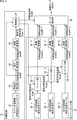
- FIG. 1 illustrates a first configuration example of an information processing apparatus to which the present disclosure is applied.
- the first configuration example includes first imaging units 11-1 to 11-4, SLAM processing units 12-1 to 12-4, and an integration unit 13.
- the first imaging unit 11-1 is composed of a high-resolution stereo camera, captures a moving image at a predetermined frame rate, and supplies the resulting stereo image pair with different parallax to the SLAM processing unit 12-1. To do.
- the second imaging unit 11-2 to the fourth imaging unit 11-4 are configured in the same manner as the first imaging unit 11-1. Instead of a stereo camera, a polarization sensor or an active sensor (ToF sensor, SL sensor, etc.) that can measure the distance (3D coordinates) between one camera and a subject may be used.
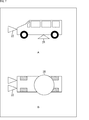
- FIG. 2 shows an example of the arrangement of the first imaging unit 11-1 to the fourth imaging unit 11-4 in the automobile.
- FIG. 2A shows a side view and
- FIG. 2B shows a top view. ing.
- the first imaging unit 11-1 to the fourth imaging unit 11-4 are arranged so that different directions are used as imaging ranges.
- the first imaging unit 11-1 is arranged on the front side of the automobile so that the imaging range is the front.
- the second imaging unit 11-2 is arranged on the right side of the automobile so that the right side is the imaging range.
- the third imaging unit 11-3 is arranged on the left side of the automobile so that the left side is the imaging range.
- the fourth imaging unit 11-4 is arranged on the rear side of the automobile so that the rear side is the imaging range.
- the arrangement of the first imaging unit 11-1 to the fourth imaging unit 11-4 is not limited to the arrangement example of FIG. 2, and the surroundings of the automobile can be imaged by a plurality of high-resolution stereo cameras. You can do it.
- any one of the second imaging unit 11-2 to the fourth imaging unit 11-4 may be arranged below the automobile so that the road surface is an imaging range.
- the SLAM processing unit 12-1 performs SLAM processing on a pair of stereo images with different parallax that are sequentially supplied from the first imaging unit 11-1 at a predetermined frame rate, and the resulting pose and its reliability Is output to the integration unit 13.
- the pose is a self-position of 6 DOF.
- the reliability includes at least one of the number of effective feature points, a three-dimensional space portion of the feature points, a difference from the last pose obtained immediately before, or a residual in an optimization operation in estimation.
- the SLAM processing units 12-2 to 12-4 perform SLAM processing on stereo image pairs with different parallaxes sequentially supplied at a predetermined frame rate from the previous stage.
- the pose and its reliability are output to the integration unit 13.
- SLAM processing performed by the SLAM processing units 12-1 to 12-4 may be executed by a so-called cloud server.
- the integration unit 13 integrates the poses input from the SLAM processing units 12-1 to 12-4 based on the reliability and determines a final pose. Specifically, the poses input from the SLAM processing units 12-1 to 12-4 are weighted and averaged based on their reliability, the pose with the highest reliability is adopted, the SLAM processing units 12-1 to 12-4 The final pose is determined by integrating the poses input from 12-4 by a Kalman filter based on the reliability.
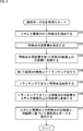
- FIG. 3 is a flowchart for explaining final pose determination processing according to the first configuration example of the information processing apparatus.
- combinations of the SLAM processing units 12-1 to 12-4 corresponding to the first imaging unit 11-1 to the fourth imaging unit 11-4 will be referred to as stereo camera systems, respectively.
- the imaging unit 11 When there is no need to distinguish the first imaging unit 11-1 to the fourth imaging unit 11-4, they are referred to as the imaging unit 11, and the SLAM processing units 12-1 to 12-4 are individually distinguished. When there is no need to do this, it is referred to as a SLAM processing unit 12.
- step S1 the imaging unit 11 of each stereo camera system starts imaging a moving image at a predetermined frame rate, and supplies the stereo image pair obtained as a result with different parallaxes to the SLAM processing unit 12.
- step S2 the SLAM processing unit 12 of each stereo camera system performs SLAM processing on a pair of stereo images having different parallaxes that are sequentially supplied from the imaging unit 11 in the previous stage, and in step S3, The resulting pose and its reliability are output to the integration unit 13.
- step S4 the integration unit 13 determines the final pose by integrating the poses input from the SLAM processing unit 12 of each stereo camera system based on the reliability. Specifically, any of the three types of integration methods described above may be employed.
- the number of stereo camera systems is not limited to four but may be two or more. Of course, if the number increases, the accuracy of the final pose can be improved.
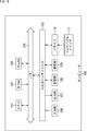
- FIG. 4 illustrates a second configuration example of the information processing apparatus to which the present disclosure is applied.
- the second configuration example is roughly composed of a 3D estimation unit 21, a 2D tracking unit 27, and a pause estimation unit 31.
- the 3D estimation unit 21 includes a stereo imaging unit 22, a feature point detection unit 23, a depth estimation unit 24, a coordinate conversion unit 25, and a holding unit 26.
- the stereo imaging unit 22 includes a high-resolution stereo camera that captures the front of the automobile.
- the stereo imaging unit 22 captures a moving image at a predetermined frame rate, and obtains a stereo image pair having different parallax as a feature point detection unit 23. Supply.
- the feature point detection unit 23 detects a texture region having a feature from the stereo image pair supplied from the stereo imaging unit 22, detects one or more feature points from the texture region, and indicates a detection result 2D feature point group @ cam0 is output to the depth estimation unit 24.
- the depth estimation unit 24 performs the process of estimating the depth of the feature points in the stereo image pair, that is, the process of estimating the 3D coordinates of the feature points, and holds the 3D feature point group @ cam0 indicating the processing result and the coordinate conversion unit 25. To the unit 26.
- the 2D coordinates are estimated, and the estimated 2D feature point group @cam [1] obtained as a result is output to the holding unit 26.
- the 2D coordinates in the image are estimated, and the estimated 2D feature point group @cam [2] obtained as a result is output to the holding unit 26.
- the coordinate conversion unit 25 performs a third imaging of the feature points in the stereo image pair by the third imaging unit 28-3 (described later) based on the 3D feature point group @ cam0 obtained from the depth estimation unit 24.
- the 2D coordinates in the image are estimated, and the estimated 2D feature point group @cam [3] obtained as a result is output to the holding unit 26.
- the 2D tracking unit 27 includes a first imaging unit 28-1 to a third imaging unit 28-3, tracking units 29-1 to 29-3, and coordinate conversion units 30-1 to 30-3.
- the first imaging unit 28-1 is composed of a camera with a wide imaging range such as a wide-angle camera or a fisheye camera.
- the first imaging unit 28-1 captures a moving image at a predetermined frame rate, and detects a tracking feature point from the resulting first image.
- the second imaging unit 28-2 supplies the second image to the tracking feature point detection unit 23-2
- the third imaging unit 28-3 transmits the third image to the tracking feature point detection unit 23-2. 23-3.
- each of the first imaging unit 28-1 to the third imaging unit 28-3 is not a stereo camera in which calibration based on parallax is indispensable, but each is configured by a single wide-angle camera or the like. Therefore, the cost can be reduced as compared with the case of using a stereo camera, and the labor of calibration can be saved.
- an effective texture range is selected from the first to third images obtained from the first imaging unit 28-1 to the third imaging unit 28-3, and the high-resolution stereo camera constituting the stereo imaging unit 22 is selected.
- the direction and zoom ratio may be controlled.
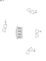
- FIG. 5 shows an arrangement example of the first imaging unit 28-1 to the third imaging unit 28-3 in the automobile.
- the first imaging unit 28-1 is attached at a position where the left side of the automobile is the imaging range, for example.
- the second imaging unit 28-2 is attached, for example, at a position where the right side of the automobile is the imaging range.
- the third imaging unit 28-3 is attached, for example, at a position where the rear of the automobile is an imaging range.
- the images may be switched selectively. Specifically, select so that the spatial distribution of feature points detected from the stereo image pair (particularly the distribution in the depth direction) is not biased, or select a feature that does not image the surrounding environment with movement, You may make it image by selecting what is imaging the texture effective as a point. Thereby, power saving can be achieved.
- an omnidirectional camera 28 having an imaging range of 360 degrees around is provided on the roof of an automobile or the like. You may arrange.
- a downward camera 28 having an imaging range on the road surface is arranged at the bottom of the automobile or the like. Also good.
- the tracking unit 29-1 acquires the estimated 2D feature point group @cam [1] from the holding unit 26, and the feature points detected from the stereo image pair based on the acquired estimated 2D feature point group @cam [1]. Are tracked on the first image obtained from the first imaging unit 28-1, and the 2D feature point group @cam [1] obtained as a result is output to the coordinate transformation unit 30-1. Of the feature points detected from the stereo image pair, feature points that do not exist on the first image are deleted from the 2D feature point group @cam [1]. Similarly, the tracking unit 29-2 outputs the 2D feature point group @cam [2] to the coordinate conversion unit 30-2, and the tracking unit 29-3 outputs the 2D feature point group @cam [3] to the coordinate conversion unit. Output to 30-3.
- the coordinate conversion unit 30-1 converts the 2D coordinates of the feature points tracked on the first image based on the 2D feature point group @cam [1] input from the tracking unit 29-1 into the 2D coordinates in the stereo image pair.
- the 2D feature point group @ cam0-1 obtained as a result is output to the pose estimation unit 31.
- the coordinate conversion unit 30-2 outputs the D feature point group @ cam0-2 to the pose estimation unit 31, and the coordinate conversion unit 30-3 outputs the D feature point group @ cam0-3 to the pose estimation unit 31. .
- the pose estimation unit 31 acquires the 3D feature point group @ cam0 from the holding unit 26, and based on the acquired 3D feature point group @ cam0 and 2D feature point group @ cam0-1 to 2D feature point group @ cam0-3 A final pose (6 DOF) is estimated that a combination of 3D coordinates and 2D coordinates can be expressed appropriately.
- FIG. 8 is a flowchart for explaining final pose determination processing according to the second configuration example of the information processing apparatus.
- the stereo imaging unit 22 has already started capturing moving images at a predetermined frame rate, and has output a stereo image pair obtained as a result to the subsequent stage.
- step S11 the feature point detection unit 23 of the 3D estimation unit 21 detects a texture region having a feature from the stereo image pair, detects one or more feature points from the texture region, and a 2D feature point group indicating a detection result.
- @ cam0 is output to the depth estimation unit 24.
- step S12 the depth estimation unit 24 estimates 3D coordinates of feature points in the stereo image pair, and outputs a 3D feature point group @ cam0 indicating the result to the coordinate conversion unit 25 and the holding unit 26.
- step S13 the coordinate conversion unit 25 estimates 2D coordinates in the first to third images of the feature points in the stereo image pair based on the 3D feature point group @ cam0, and the estimated 2D feature points obtained as a result thereof
- the first imaging unit 28-1 to the third imaging unit 28-3 of the 2D tracking unit 27 are selectively switched to start capturing a moving image.
- step S15 the tracking unit 29-i deletes the record of the feature point that could not be tracked on the i-th image from the 2D feature point group @cam [i] and outputs it to the coordinate conversion unit 30-i. To do.
- the 2D coordinates of the feature points are converted into 2D coordinates in the stereo image pair, and the resulting 2D feature point group @ cam0-i is output to the pose estimation unit 31.
- step S17 the pose estimation unit 31 acquires the 3D feature point group @ cam0 from the holding unit 26, the acquired 3D feature point group @ cam0, and the 2D feature point group @ cam0-1 to 2D feature point group @ cam0- Based on 3, a final pose (6 DOF) is estimated that the combination of 3D coordinates and 2D coordinates can be expressed appropriately.
- any one of the first imaging unit 28-1 to the third imaging unit 28-3 is specifically, Since the feature points detected from the stereo image pair can be continuously tracked, and the feature points that are not affected by the surrounding environment can be selectively switched so that the spatial distribution of the feature points is not biased, It is possible to continuously estimate the final pose.
- FIG. 9 shows a conceptual diagram when the second configuration example of the information processing apparatus is mounted on an HMD (head mounted display).
- the HMD shown in the figure is used, the user's head position and posture can be estimated continuously, so video can be presented according to the user's state in video playback and AR / VR applications. It becomes possible.
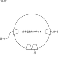
- FIG. 10 shows a conceptual diagram when the second configuration example of the information processing apparatus is mounted on an autonomous cleaning robot.
- FIG. 11 shows a conceptual diagram when the second configuration example of the information processing apparatus is mounted on a drone (autonomous unmanned aerial vehicle).
- the information processing apparatus is attached to a wild animal or the like to be protected in a small size, the position can be estimated continuously, so that it is possible to contribute to their behavior analysis.
- FIG. 12 shows a conceptual diagram when the second configuration example of the information processing apparatus is applied to creation of a 3D model and an arbitrary viewpoint video.
- each imaging unit is arranged around a stationary subject (in the case of the figure, a building), the position and orientation of each imaging unit can be estimated, so images captured by each imaging unit Can be used to create 3D models and arbitrary viewpoint videos.
- a series of processes according to the first and second configuration examples of the information processing apparatus described above can be executed by hardware or can be executed by software.
- a program constituting the software is installed in the computer.
- the computer includes, for example, a general-purpose personal computer capable of executing various functions by installing a computer incorporated in dedicated hardware and various programs.
- FIG. 13 is a block diagram showing an example of the hardware configuration of a computer that executes the above-described series of processing by a program.
- a CPU Central Processing Unit
- ROM Read Only Memory
- RAM Random Access Memory
- An input / output interface 105 is further connected to the bus 104.
- An input unit 106, an output unit 107, a storage unit 108, a communication unit 109, and a drive 110 are connected to the input / output interface 105.
- the input unit 106 includes a keyboard, a mouse, a microphone, and the like.
- the output unit 107 includes a display, a speaker, and the like.
- the storage unit 108 includes a hard disk, a nonvolatile memory, and the like.
- the communication unit 109 includes a network interface or the like.
- the drive 110 drives a removable medium 111 such as a magnetic disk, an optical disk, a magneto-optical disk, or a semiconductor memory.
- the CPU 101 loads the program stored in the storage unit 108 to the RAM 103 via the input / output interface 105 and the bus 104 and executes the program. A series of processing is performed.
- the program executed by the computer 100 may be a program that is processed in time series in the order described in this specification, or a necessary timing such as when a call is made in parallel. It may be a program in which processing is performed.
- a main imaging unit that is composed of a stereo camera mounted on a moving body and outputs a time-series stereo main image pair by capturing a moving image at a predetermined frame rate;
- One or more sub-imaging units that are mounted on the moving body so that the imaging direction is different from the main imaging unit, and that captures moving images at a predetermined frame rate;
- An information processing apparatus comprising: a stereo main image pair imaged by the main imaging unit; and a final pose determining unit that estimates a pose of the moving object based on the subimage imaged by the sub imaging unit.
- the sub-imaging unit is composed of a stereo camera, and outputs a time-series stereo sub-image pair by capturing a moving image at a predetermined frame rate
- the final pose determination unit A main estimation unit that estimates a pose of the moving object based on a time-series stereo main image pair imaged by the main imaging unit; A sub-estimator for estimating a pose of the moving body based on a time-series stereo sub-image pair imaged by the sub-imaging unit;
- the information processing apparatus further including: an integration unit that determines a final pose by integrating the pose estimated by the main estimation unit and the pose estimated by the sub-estimation unit.
- the main estimation unit estimates a 3D coordinate of a feature point detected from the stereo main image pair, and tracks the feature point over one of the plurality of frames of the stereo main image pair, thereby posing the moving body. And outputs the estimated pose and its reliability to the integration unit,
- the sub-estimator estimates a 3D coordinate of a feature point detected from the stereo sub-image pair, and tracks the feature point over one of the plurality of frames of the stereo sub-image pair, thereby posing the moving body.
- the integration unit determines a final pose by integrating the pose estimated by the main estimation unit and the pose estimated by the sub-estimation unit based on the reliability.
- Information processing device is a 3D coordinate of a feature point detected from the stereo main image pair, and tracks the feature point over one of the plurality of frames of the stereo main image pair, thereby posing the moving body.
- the reliability is the number of the feature points effective in estimating the pose, the 3D spatial distribution of the feature points, the difference between the estimated pose and the last final pose, or the remaining in the optimization calculation in the estimation.
- the information processing apparatus according to (3) including at least one of the differences.
- the sub-imaging unit is composed of a wide-angle camera, a fish-eye camera, or an omnidirectional camera, and outputs a time-series sub-image by capturing a moving image at a predetermined frame rate.
- the final pose determination unit A 3D estimation unit that estimates 3D coordinates of feature points detected from the stereo main image pair imaged by the main imaging unit; A 2D tracking unit that tracks the feature points over a plurality of frames of the sub-image and converts a tracking result into 2D coordinates in the stereo main image pair; A pose estimation unit that estimates a final pose based on the 3D coordinates of the feature points estimated by a 3D estimation unit and the 2D coordinates of the feature points in the stereo main image pair converted by the 2D tracking unit; The information processing apparatus according to (1).
- the 3D estimation unit estimates 3D coordinates of feature points detected from the stereo main image pair imaged by the main imaging unit, and estimates 2D coordinates of the feature points in the sub-image
- the 2D tracking unit tracks the feature point over a plurality of frames of the sub-image based on the 2D coordinates in the sub-image of the feature point estimated by the 3D estimation unit, and the tracking result is recorded on the stereo main image.
- the information processing apparatus according to (5), wherein the information is converted into 2D coordinates in the image pair.
- the plurality of sub-imaging units perform imaging while being selectively switched based on an estimation result of the 2D coordinates in the sub-image of the feature point by the 3D estimation unit.
- Information processing device is described by the 3D estimation unit.
- a stereo main image pair captured by a main image capturing unit configured to output a time-series stereo main image pair by capturing a moving image at a predetermined frame rate, the stereo main image pair including a stereo camera mounted on a moving body, and the main image capturing
- the pose of the moving body is estimated based on the sub-image captured by one or a plurality of sub-imaging units that are mounted on the moving body so that the imaging direction differs from that of the unit and that captures a moving image at a predetermined frame rate.
- Information processing method including a final pose determination step.
- a stereo main image pair captured by a main image capturing unit configured to output a time-series stereo main image pair by capturing a moving image at a predetermined frame rate, the stereo main image pair including a stereo camera mounted on a moving body, and the main image capturing
- the pose of the moving body is estimated based on the sub-image captured by one or a plurality of sub-imaging units that are mounted on the moving body so that the imaging direction differs from that of the unit and that captures a moving image at a predetermined frame rate.
- a program that causes a computer of an information processing device to execute processing including a final pose determination step.
Landscapes
- Engineering & Computer Science (AREA)
- Computer Vision & Pattern Recognition (AREA)
- Physics & Mathematics (AREA)
- General Physics & Mathematics (AREA)
- Theoretical Computer Science (AREA)
- Multimedia (AREA)
- Signal Processing (AREA)
- Image Analysis (AREA)
- Length Measuring Devices By Optical Means (AREA)
- Studio Devices (AREA)
- Testing, Inspecting, Measuring Of Stereoscopic Televisions And Televisions (AREA)
Abstract
Description
図1は、本開示を適用した情報処理装置の第1の構成例を示している。
次に、図3は、情報処理装置の第1の構成例による最終ポーズ決定処理を説明するフローチャートである。
図4は、本開示を適用した情報処理装置の第2の構成例を示している。
次に、図8は、情報処理装置の第2の構成例による最終ポーズ決定処理を説明するフローチャートである。
上述した実施の形態では、車載用途を想定していたが、情報処理装置の第1および第2の構成例は車載用途以外への応用も可能である。
(1)
移動体に搭載されたステレオカメラから構成され、所定のフレームレートで動画像を撮像することにより時系列のステレオ主画像対を出力する主撮像部と、
前記主撮像部とは撮像方向が異なるように前記移動体に搭載され、所定のフレームレートで動画像を撮像する1または複数の副撮像部と、
前記主撮像部によって撮像されたステレオ主画像対と、前記副撮像部によって撮像された副画像とに基づいて前記移動体のポーズを推定する最終ポーズ決定部と
を備える情報処理装置。
(2)
前記副撮像部は、ステレオカメラから構成され、所定のフレームレートで動画像を撮像することにより時系列のステレオ副画像対を出力し、
前記最終ポーズ決定部は、
前記主撮像部によって撮像された時系列のステレオ主画像対に基づいて前記移動体のポーズを推定する主推定部と、
前記副撮像部によって撮像された時系列のステレオ副画像対に基づいて前記移動体のポーズを推定する副推定部と、
前記主推定部によって推定されたポーズと、前記副推定部によって推定されたポーズとを統合することにより最終ポーズを決定する統合部とを有する
前記(1)に記載の情報処理装置。
(3)
前記主推定部は、前記ステレオ主画像対から検出した特徴点の3D座標と推定するとともに、前記特徴点を前記ステレオ主画像対の一方の複数フレームに亘ってトラッキングすることによって前記移動体のポーズを推定し、推定したポーズとその信頼度を前記統合部に出力し、
前記副推定部は、前記ステレオ副画像対から検出した特徴点の3D座標と推定するとともに、前記特徴点を前記ステレオ副画像対の一方の複数フレームに亘ってトラッキングすることによって前記移動体のポーズを推定し、推定したポーズとその信頼度を前記統合部に出力し、
前記統合部は、前記信頼度に基づいて、前記主推定部によって推定されたポーズと、前記副推定部によって推定されたポーズとを統合することにより最終ポーズを決定する
前記(2)に記載の情報処理装置。
(4)
前記信頼度は、前記ポーズを推定するに際して有効な前記特徴点の数、前記特徴点の3D空間分布、推定された前記ポーズと直近の最終ポーズとの差分、または、推定における最適化演算における残差のうちの少なくとも一つを含む
前記(3)に記載の情報処理装置。
(5)
前記副撮像部は、広角カメラ、魚眼カメラ、または全方位カメラから構成され、所定のフレームレートで動画像を撮像することにより、時系列の副画像を出力し、
前記最終ポーズ決定部は、
前記主撮像部によって撮像された前記ステレオ主画像対から検出した特徴点の3D座標を推定する3D推定部と、
前記特徴点を前記副画像の複数フレームに亘ってトラッキングし、トラッキング結果を前記ステレオ主画像対における2D座標に変換する2Dトラッキング部と、
3D推定部によって推定された前記特徴点の前記3D座標と、前記2Dトラッキング部によって変換された前記特徴点の前記ステレオ主画像対における2D座標とに基づいて最終ポーズを推定するポーズ推定部とを有する
前記(1)に記載の情報処理装置。
(6)
前記3D推定部は、前記主撮像部によって撮像された前記ステレオ主画像対から検出した特徴点の3D座標を推定するとともに、前記特徴点の前記副画像における2D座標を推定し、
前記2Dトラッキング部は、前記3D推定部によって推定された前記特徴点の前記副画像における前記2D座標に基づき、前記特徴点を前記副画像の複数フレームに亘ってトラッキングし、トラッキング結果を前記ステレオ主画像対における2D座標に変換する
前記(5)に記載の情報処理装置。
(7)
複数の前記副撮像部は、前記3D推定部による前記特徴点の前記副画像における前記2D座標に推定結果に基づき、選択的に切り替えられて撮像を行う
前記(5)または(6)に記載の情報処理装置。
(8)
情報処理装置による情報処理方法において、
前記情報処理装置による、
移動体に搭載されたステレオカメラから構成され、所定のフレームレートで動画像を撮像することにより時系列のステレオ主画像対を出力する主撮像部によって撮像されたステレオ主画像対と、前記主撮像部とは撮像方向が異なるように前記移動体に搭載され、所定のフレームレートで動画像を撮像する1または複数の副撮像部によって撮像された副画像とに基づいて前記移動体のポーズを推定する最終ポーズ決定ステップを
含む情報処理方法。
(9)
情報処理装置の制御用のプログラムにおいて、
移動体に搭載されたステレオカメラから構成され、所定のフレームレートで動画像を撮像することにより時系列のステレオ主画像対を出力する主撮像部によって撮像されたステレオ主画像対と、前記主撮像部とは撮像方向が異なるように前記移動体に搭載され、所定のフレームレートで動画像を撮像する1または複数の副撮像部によって撮像された副画像とに基づいて前記移動体のポーズを推定する最終ポーズ決定ステップを
含む処理を情報処理装置のコンピュータに実行させるプログラム。
Claims (9)
- 移動体に搭載されたステレオカメラから構成され、所定のフレームレートで動画像を撮像することにより時系列のステレオ主画像対を出力する主撮像部と、
前記主撮像部とは撮像方向が異なるように前記移動体に搭載され、所定のフレームレートで動画像を撮像する1または複数の副撮像部と、
前記主撮像部によって撮像されたステレオ主画像対と、前記副撮像部によって撮像された副画像とに基づいて前記移動体のポーズを推定する最終ポーズ決定部と
を備える情報処理装置。 - 前記副撮像部は、ステレオカメラから構成され、所定のフレームレートで動画像を撮像することにより時系列のステレオ副画像対を出力し、
前記最終ポーズ決定部は、
前記主撮像部によって撮像された時系列のステレオ主画像対に基づいて前記移動体のポーズを推定する主推定部と、
前記副撮像部によって撮像された時系列のステレオ副画像対に基づいて前記移動体のポーズを推定する副推定部と、
前記主推定部によって推定されたポーズと、前記副推定部によって推定されたポーズとを統合することにより最終ポーズを決定する統合部とを有する
請求項1に記載の情報処理装置。 - 前記主推定部は、前記ステレオ主画像対から検出した特徴点の3D座標と推定するとともに、前記特徴点を前記ステレオ主画像対の一方の複数フレームに亘ってトラッキングすることによって前記移動体のポーズを推定し、推定したポーズとその信頼度を前記統合部に出力し、
前記副推定部は、前記ステレオ副画像対から検出した特徴点の3D座標と推定するとともに、前記特徴点を前記ステレオ副画像対の一方の複数フレームに亘ってトラッキングすることによって前記移動体のポーズを推定し、推定したポーズとその信頼度を前記統合部に出力し、
前記統合部は、前記信頼度に基づいて、前記主推定部によって推定されたポーズと、前記副推定部によって推定されたポーズとを統合することにより最終ポーズを決定する
請求項2に記載の情報処理装置。 - 前記信頼度は、前記ポーズを推定するに際して有効な前記特徴点の数、前記特徴点の3D空間分布、推定された前記ポーズと直近の最終ポーズとの差分、または、推定における最適化演算における残差のうちの少なくとも一つを含む
請求項3に記載の情報処理装置。 - 前記副撮像部は、広角カメラ、魚眼カメラ、または全方位カメラから構成され、所定のフレームレートで動画像を撮像することにより、時系列の副画像を出力し、
前記最終ポーズ決定部は、
前記主撮像部によって撮像された前記ステレオ主画像対から検出した特徴点の3D座標を推定する3D推定部と、
前記特徴点を前記副画像の複数フレームに亘ってトラッキングし、トラッキング結果を前記ステレオ主画像対における2D座標に変換する2Dトラッキング部と、
3D推定部によって推定された前記特徴点の前記3D座標と、前記2Dトラッキング部によって変換された前記特徴点の前記ステレオ主画像対における2D座標とに基づいて最終ポーズを推定するポーズ推定部とを有する
請求項1に記載の情報処理装置。 - 前記3D推定部は、前記主撮像部によって撮像された前記ステレオ主画像対から検出した特徴点の3D座標を推定するとともに、前記特徴点の前記副画像における2D座標を推定し、
前記2Dトラッキング部は、前記3D推定部によって推定された前記特徴点の前記副画像における前記2D座標に基づき、前記特徴点を前記副画像の複数フレームに亘ってトラッキングし、トラッキング結果を前記ステレオ主画像対における2D座標に変換する
請求項5に記載の情報処理装置。 - 複数の前記副撮像部は、前記3D推定部による前記特徴点の前記副画像における前記2D座標に推定結果に基づき、選択的に切り替えられて撮像を行う
請求項6に記載の情報処理装置。 - 情報処理装置による情報処理方法において、
前記情報処理装置による、
移動体に搭載されたステレオカメラから構成され、所定のフレームレートで動画像を撮像することにより時系列のステレオ主画像対を出力する主撮像部によって撮像されたステレオ主画像対と、前記主撮像部とは撮像方向が異なるように前記移動体に搭載され、所定のフレームレートで動画像を撮像する1または複数の副撮像部によって撮像された副画像とに基づいて前記移動体のポーズを推定する最終ポーズ決定ステップを
含む情報処理方法。 - 情報処理装置の制御用のプログラムにおいて、
移動体に搭載されたステレオカメラから構成され、所定のフレームレートで動画像を撮像することにより時系列のステレオ主画像対を出力する主撮像部によって撮像されたステレオ主画像対と、前記主撮像部とは撮像方向が異なるように前記移動体に搭載され、所定のフレームレートで動画像を撮像する1または複数の副撮像部によって撮像された副画像とに基づいて前記移動体のポーズを推定する最終ポーズ決定ステップを
含む処理を情報処理装置のコンピュータに実行させるプログラム。
Priority Applications (4)
| Application Number | Priority Date | Filing Date | Title |
|---|---|---|---|
| JP2017543143A JP6872128B2 (ja) | 2015-09-30 | 2016-09-16 | 情報処理装置、情報処理方法、およびプログラム |
| EP16851228.3A EP3358294A4 (en) | 2015-09-30 | 2016-09-16 | INFORMATION PROCESSING DEVICE, INFORMATION PROCESSING PROCESS AND PROGRAM |
| US15/761,893 US10803600B2 (en) | 2015-09-30 | 2016-09-16 | Information processing device, information processing method, and program |
| CN201680055412.2A CN108449945B (zh) | 2015-09-30 | 2016-09-16 | 信息处理设备、信息处理方法和程序 |
Applications Claiming Priority (2)
| Application Number | Priority Date | Filing Date | Title |
|---|---|---|---|
| JP2015-194554 | 2015-09-30 | ||
| JP2015194554 | 2015-09-30 |
Publications (1)
| Publication Number | Publication Date |
|---|---|
| WO2017057054A1 true WO2017057054A1 (ja) | 2017-04-06 |
Family
ID=58423641
Family Applications (1)
| Application Number | Title | Priority Date | Filing Date |
|---|---|---|---|
| PCT/JP2016/077427 Ceased WO2017057054A1 (ja) | 2015-09-30 | 2016-09-16 | 情報処理装置、情報処理方法、およびプログラム |
Country Status (5)
| Country | Link |
|---|---|
| US (1) | US10803600B2 (ja) |
| EP (1) | EP3358294A4 (ja) |
| JP (1) | JP6872128B2 (ja) |
| CN (1) | CN108449945B (ja) |
| WO (1) | WO2017057054A1 (ja) |
Cited By (7)
| Publication number | Priority date | Publication date | Assignee | Title |
|---|---|---|---|---|
| WO2019026390A1 (ja) * | 2017-08-01 | 2019-02-07 | ソニー株式会社 | 情報処理装置、情報処理方法、記録媒体、及び撮像装置 |
| JP2020531793A (ja) * | 2017-08-31 | 2020-11-05 | クロネス アーゲー | 測定ビークルによってエリアを測定するための方法 |
| JP2021043486A (ja) * | 2019-09-06 | 2021-03-18 | 株式会社東芝 | 位置推定装置 |
| JP2022533309A (ja) * | 2019-05-21 | 2022-07-22 | マイクロソフト テクノロジー ライセンシング,エルエルシー | 画像ベースの位置特定 |
| WO2022186354A1 (ja) * | 2021-03-03 | 2022-09-09 | 株式会社Preferred Networks | 情報処理装置および自律移動ロボット |
| JP2022166505A (ja) * | 2021-04-21 | 2022-11-02 | 株式会社東芝 | 3次元マップ推定装置および障害物検出装置 |
| WO2024075525A1 (ja) * | 2022-10-05 | 2024-04-11 | ソニーグループ株式会社 | 情報処理装置およびプログラム |
Families Citing this family (12)
| Publication number | Priority date | Publication date | Assignee | Title |
|---|---|---|---|---|
| JP6883215B2 (ja) | 2015-09-29 | 2021-06-09 | ソニーグループ株式会社 | 計測装置および方法、並びにプログラム |
| JP6872128B2 (ja) * | 2015-09-30 | 2021-05-19 | ソニーグループ株式会社 | 情報処理装置、情報処理方法、およびプログラム |
| CN108139202B (zh) | 2015-09-30 | 2021-06-11 | 索尼公司 | 图像处理装置、图像处理方法和程序 |
| US10587863B2 (en) | 2015-09-30 | 2020-03-10 | Sony Corporation | Image processing apparatus, image processing method, and program |
| US10723018B2 (en) * | 2016-11-28 | 2020-07-28 | Brain Corporation | Systems and methods for remote operating and/or monitoring of a robot |
| US20200226787A1 (en) * | 2019-01-14 | 2020-07-16 | Sony Corporation | Information processing apparatus, information processing method, and program |
| CN113632459A (zh) * | 2019-03-27 | 2021-11-09 | 索尼集团公司 | 信息处理装置、方法和程序 |
| US11654552B2 (en) * | 2019-07-29 | 2023-05-23 | TruPhysics GmbH | Backup control based continuous training of robots |
| JP7249919B2 (ja) * | 2019-09-17 | 2023-03-31 | 株式会社東芝 | 推定装置、推定方法及びプログラム |
| US12028619B2 (en) * | 2020-03-05 | 2024-07-02 | Sony Group Corporation | Image processing device and image processing method |
| JP7444646B2 (ja) * | 2020-03-11 | 2024-03-06 | 株式会社メガチップス | ポーズデータ生成装置、cgデータ生成システム、ポーズデータ生成方法、および、プログラム |
| CN113726465B (zh) * | 2020-05-26 | 2022-12-27 | 华为技术有限公司 | 时间戳同步方法和设备 |
Citations (4)
| Publication number | Priority date | Publication date | Assignee | Title |
|---|---|---|---|---|
| JP2007278871A (ja) * | 2006-04-07 | 2007-10-25 | Technical Research & Development Institute Ministry Of Defence | 動き量計算装置 |
| JP2010014450A (ja) * | 2008-07-01 | 2010-01-21 | Topcon Corp | 位置測定方法、位置測定装置、およびプログラム |
| WO2012176249A1 (ja) * | 2011-06-21 | 2012-12-27 | 国立大学法人奈良先端科学技術大学院大学 | 自己位置推定装置、自己位置推定方法、自己位置推定プログラム、及び移動体 |
| JP2014216813A (ja) * | 2013-04-25 | 2014-11-17 | 日本放送協会 | カメラ姿勢推定装置及びそのプログラム |
Family Cites Families (25)
| Publication number | Priority date | Publication date | Assignee | Title |
|---|---|---|---|---|
| JP3833786B2 (ja) * | 1997-08-04 | 2006-10-18 | 富士重工業株式会社 | 移動体の3次元自己位置認識装置 |
| DE10244148A1 (de) * | 2002-09-23 | 2004-04-08 | Daimlerchrysler Ag | Verfahren und Vorrichtung zur videobasierten Beobachtung und Vermessung der seitlichen Umgebung eines Fahrzeugs |
| US7576639B2 (en) * | 2006-03-14 | 2009-08-18 | Mobileye Technologies, Ltd. | Systems and methods for detecting pedestrians in the vicinity of a powered industrial vehicle |
| US7925049B2 (en) * | 2006-08-15 | 2011-04-12 | Sri International | Stereo-based visual odometry method and system |
| JP5380789B2 (ja) | 2007-06-06 | 2014-01-08 | ソニー株式会社 | 情報処理装置、および情報処理方法、並びにコンピュータ・プログラム |
| EP2309225A4 (en) * | 2008-07-01 | 2014-10-15 | Topcon Corp | POSITION MEASUREMENT METHOD, POSITION MEASUREMENT DEVICE AND PROGRAM |
| JP5448617B2 (ja) * | 2008-08-19 | 2014-03-19 | パナソニック株式会社 | 距離推定装置、距離推定方法、プログラム、集積回路およびカメラ |
| US8698875B2 (en) * | 2009-02-20 | 2014-04-15 | Google Inc. | Estimation of panoramic camera orientation relative to a vehicle coordinate frame |
| JP2011215963A (ja) | 2010-03-31 | 2011-10-27 | Sony Corp | 電子機器、画像処理方法及びプログラム |
| US20120114181A1 (en) * | 2010-11-01 | 2012-05-10 | Borthwick James R | Vehicle pose estimation and load profiling |
| KR20120070291A (ko) * | 2010-12-21 | 2012-06-29 | 삼성전자주식회사 | 보행 로봇 및 그의 동시 위치 인식 및 지도 작성 방법 |
| US9357208B2 (en) * | 2011-04-25 | 2016-05-31 | Magna Electronics Inc. | Method and system for dynamically calibrating vehicular cameras |
| US9538144B2 (en) * | 2012-05-02 | 2017-01-03 | GM Global Technology Operations LLC | Full speed lane sensing using multiple cameras |
| JP5901447B2 (ja) * | 2012-06-27 | 2016-04-13 | オリンパス株式会社 | 画像処理装置及びそれを備えた撮像装置、画像処理方法、並びに画像処理プログラム |
| US9563951B2 (en) * | 2013-05-21 | 2017-02-07 | Magna Electronics Inc. | Vehicle vision system with targetless camera calibration |
| KR102003776B1 (ko) * | 2013-08-13 | 2019-07-26 | 한화테크윈 주식회사 | 감시용 카메라의 자세 검출 방법 및 장치 |
| US9201424B1 (en) * | 2013-08-27 | 2015-12-01 | Google Inc. | Camera calibration using structure from motion techniques |
| US10061324B2 (en) * | 2014-07-30 | 2018-08-28 | Hitachi, Ltd. | Autonomous moving device and self position estimation method |
| JP6433200B2 (ja) * | 2014-08-28 | 2018-12-05 | 株式会社トプコン | 演算装置、演算方法、およびプログラム |
| US10013761B2 (en) * | 2015-03-24 | 2018-07-03 | Intel Corporation | Automatic orientation estimation of camera system relative to vehicle |
| JP6883215B2 (ja) | 2015-09-29 | 2021-06-09 | ソニーグループ株式会社 | 計測装置および方法、並びにプログラム |
| CN108139202B (zh) | 2015-09-30 | 2021-06-11 | 索尼公司 | 图像处理装置、图像处理方法和程序 |
| US10587863B2 (en) | 2015-09-30 | 2020-03-10 | Sony Corporation | Image processing apparatus, image processing method, and program |
| JP6872128B2 (ja) * | 2015-09-30 | 2021-05-19 | ソニーグループ株式会社 | 情報処理装置、情報処理方法、およびプログラム |
| US9727793B2 (en) * | 2015-12-15 | 2017-08-08 | Honda Motor Co., Ltd. | System and method for image based vehicle localization |
-
2016
- 2016-09-16 JP JP2017543143A patent/JP6872128B2/ja active Active
- 2016-09-16 WO PCT/JP2016/077427 patent/WO2017057054A1/ja not_active Ceased
- 2016-09-16 US US15/761,893 patent/US10803600B2/en active Active
- 2016-09-16 EP EP16851228.3A patent/EP3358294A4/en not_active Withdrawn
- 2016-09-16 CN CN201680055412.2A patent/CN108449945B/zh active Active
Patent Citations (4)
| Publication number | Priority date | Publication date | Assignee | Title |
|---|---|---|---|---|
| JP2007278871A (ja) * | 2006-04-07 | 2007-10-25 | Technical Research & Development Institute Ministry Of Defence | 動き量計算装置 |
| JP2010014450A (ja) * | 2008-07-01 | 2010-01-21 | Topcon Corp | 位置測定方法、位置測定装置、およびプログラム |
| WO2012176249A1 (ja) * | 2011-06-21 | 2012-12-27 | 国立大学法人奈良先端科学技術大学院大学 | 自己位置推定装置、自己位置推定方法、自己位置推定プログラム、及び移動体 |
| JP2014216813A (ja) * | 2013-04-25 | 2014-11-17 | 日本放送協会 | カメラ姿勢推定装置及びそのプログラム |
Non-Patent Citations (1)
| Title |
|---|
| See also references of EP3358294A4 * |
Cited By (18)
| Publication number | Priority date | Publication date | Assignee | Title |
|---|---|---|---|---|
| JP7160036B2 (ja) | 2017-08-01 | 2022-10-25 | ソニーグループ株式会社 | 情報処理装置、情報処理方法、記録媒体、及び撮像装置 |
| JPWO2019026390A1 (ja) * | 2017-08-01 | 2020-06-11 | ソニー株式会社 | 情報処理装置、情報処理方法、記録媒体、及び撮像装置 |
| US11257248B2 (en) | 2017-08-01 | 2022-02-22 | Sony Corporation | Information processing device, information processing method, recording medium, and image capturing apparatus for self-position-posture estimation |
| WO2019026390A1 (ja) * | 2017-08-01 | 2019-02-07 | ソニー株式会社 | 情報処理装置、情報処理方法、記録媒体、及び撮像装置 |
| US11842515B2 (en) | 2017-08-01 | 2023-12-12 | Sony Group Corporation | Information processing device, information processing method, and image capturing apparatus for self-position-posture estimation |
| JP2020531793A (ja) * | 2017-08-31 | 2020-11-05 | クロネス アーゲー | 測定ビークルによってエリアを測定するための方法 |
| US12235093B2 (en) | 2017-08-31 | 2025-02-25 | Krones Ag | Method for designing packaging plants |
| JP7506091B2 (ja) | 2019-05-21 | 2024-06-25 | マイクロソフト テクノロジー ライセンシング,エルエルシー | 画像ベースの位置特定 |
| JP2022533309A (ja) * | 2019-05-21 | 2022-07-22 | マイクロソフト テクノロジー ライセンシング,エルエルシー | 画像ベースの位置特定 |
| US11461928B2 (en) | 2019-09-06 | 2022-10-04 | Kabushiki Kaisha Toshiba | Location estimation apparatus |
| JP2022190173A (ja) * | 2019-09-06 | 2022-12-22 | 株式会社東芝 | 位置推定装置 |
| JP7573004B2 (ja) | 2019-09-06 | 2024-10-24 | 株式会社東芝 | 位置推定装置 |
| JP2021043486A (ja) * | 2019-09-06 | 2021-03-18 | 株式会社東芝 | 位置推定装置 |
| WO2022186354A1 (ja) * | 2021-03-03 | 2022-09-09 | 株式会社Preferred Networks | 情報処理装置および自律移動ロボット |
| JP2022166505A (ja) * | 2021-04-21 | 2022-11-02 | 株式会社東芝 | 3次元マップ推定装置および障害物検出装置 |
| US12112502B2 (en) | 2021-04-21 | 2024-10-08 | Kabushiki Kaisha Toshiba | Three-dimensional map estimation apparatus and obstacle detection apparatus |
| JP7577600B2 (ja) | 2021-04-21 | 2024-11-05 | 株式会社東芝 | 3次元マップ推定装置および障害物検出装置 |
| WO2024075525A1 (ja) * | 2022-10-05 | 2024-04-11 | ソニーグループ株式会社 | 情報処理装置およびプログラム |
Also Published As
| Publication number | Publication date |
|---|---|
| EP3358294A1 (en) | 2018-08-08 |
| EP3358294A4 (en) | 2019-04-10 |
| US10803600B2 (en) | 2020-10-13 |
| JPWO2017057054A1 (ja) | 2018-08-02 |
| CN108449945B (zh) | 2020-12-08 |
| CN108449945A (zh) | 2018-08-24 |
| JP6872128B2 (ja) | 2021-05-19 |
| US20180286056A1 (en) | 2018-10-04 |
Similar Documents
| Publication | Publication Date | Title |
|---|---|---|
| JP6872128B2 (ja) | 情報処理装置、情報処理方法、およびプログラム | |
| KR101725060B1 (ko) | 그래디언트 기반 특징점을 이용한 이동 로봇의 위치를 인식하기 위한 장치 및 그 방법 | |
| KR101776621B1 (ko) | 에지 기반 재조정을 이용하여 이동 로봇의 위치를 인식하기 위한 장치 및 그 방법 | |
| KR102658707B1 (ko) | 화상 처리 장치 및 방법, 및 화상 처리 시스템 | |
| US9398287B2 (en) | Context-based depth sensor control | |
| WO2018159168A1 (en) | System and method for virtually-augmented visual simultaneous localization and mapping | |
| JP2018522348A (ja) | センサーの3次元姿勢を推定する方法及びシステム | |
| JP7063760B2 (ja) | 移動体 | |
| JP2014138420A (ja) | 自律車両用の奥行き検知方法及びシステム | |
| CN102870137A (zh) | 用于基于2d运动估计相对3d速度和加速度投影函数的数据挖掘方法和系统 | |
| GB2548970A (en) | Method and device for generating an image of an area surrounding a vehicle | |
| EP2998934B1 (en) | Image processing device, image processing method, and program | |
| JP2021193538A (ja) | 情報処理装置、移動装置、情報処理システム、および方法、並びにプログラム | |
| JP2007263657A (ja) | 3次元座標取得装置 | |
| WO2021210213A1 (ja) | 移動体検知システム及び情報管理装置 | |
| KR102404867B1 (ko) | 3차원 거리정보를 이용한 랩어라운드뷰 영상제공장치 및 방법 | |
| CN113661513A (zh) | 一种图像处理方法、设备、图像处理系统及存储介质 | |
| Karrer et al. | Real-time dense surface reconstruction for aerial manipulation | |
| US11842515B2 (en) | Information processing device, information processing method, and image capturing apparatus for self-position-posture estimation | |
| WO2019188392A1 (ja) | 情報処理装置、情報処理方法、プログラム、及び、移動体 | |
| JP2020030721A (ja) | 移動体 | |
| JP2013130911A (ja) | 位置特定装置 | |
| WO2024009377A1 (ja) | 情報処理装置、自己位置推定方法、及び非一時的なコンピュータ可読媒体 | |
| US12276986B2 (en) | Self-localizing system operative in an unknown environment | |
| JP4027294B2 (ja) | 移動体検出装置、移動体検出方法及び移動体検出プログラム |
Legal Events
| Date | Code | Title | Description |
|---|---|---|---|
| 121 | Ep: the epo has been informed by wipo that ep was designated in this application |
Ref document number: 16851228 Country of ref document: EP Kind code of ref document: A1 |
|
| ENP | Entry into the national phase |
Ref document number: 2017543143 Country of ref document: JP Kind code of ref document: A |
|
| WWE | Wipo information: entry into national phase |
Ref document number: 15761893 Country of ref document: US |
|
| NENP | Non-entry into the national phase |
Ref country code: DE |
|
| WWE | Wipo information: entry into national phase |
Ref document number: 2016851228 Country of ref document: EP |