WO2017068743A1 - 路面状態判定装置、撮像装置、撮像システムおよび路面状態判定方法 - Google Patents
路面状態判定装置、撮像装置、撮像システムおよび路面状態判定方法 Download PDFInfo
- Publication number
- WO2017068743A1 WO2017068743A1 PCT/JP2016/003929 JP2016003929W WO2017068743A1 WO 2017068743 A1 WO2017068743 A1 WO 2017068743A1 JP 2016003929 W JP2016003929 W JP 2016003929W WO 2017068743 A1 WO2017068743 A1 WO 2017068743A1
- Authority
- WO
- WIPO (PCT)
- Prior art keywords
- road surface
- luminance
- wet
- image
- continuous
- Prior art date
- Legal status (The legal status is an assumption and is not a legal conclusion. Google has not performed a legal analysis and makes no representation as to the accuracy of the status listed.)
- Ceased
Links
Images





Classifications
-
- G—PHYSICS
- G01—MEASURING; TESTING
- G01N—INVESTIGATING OR ANALYSING MATERIALS BY DETERMINING THEIR CHEMICAL OR PHYSICAL PROPERTIES
- G01N21/00—Investigating or analysing materials by the use of optical means, i.e. using sub-millimetre waves, infrared, visible or ultraviolet light
- G01N21/17—Systems in which incident light is modified in accordance with the properties of the material investigated
- G01N21/55—Specular reflectivity
-
- B—PERFORMING OPERATIONS; TRANSPORTING
- B60—VEHICLES IN GENERAL
- B60W—CONJOINT CONTROL OF VEHICLE SUB-UNITS OF DIFFERENT TYPE OR DIFFERENT FUNCTION; CONTROL SYSTEMS SPECIALLY ADAPTED FOR HYBRID VEHICLES; ROAD VEHICLE DRIVE CONTROL SYSTEMS FOR PURPOSES NOT RELATED TO THE CONTROL OF A PARTICULAR SUB-UNIT
- B60W40/00—Estimation or calculation of non-directly measurable driving parameters for road vehicle drive control systems not related to the control of a particular sub unit, e.g. by using mathematical models
- B60W40/02—Estimation or calculation of non-directly measurable driving parameters for road vehicle drive control systems not related to the control of a particular sub unit, e.g. by using mathematical models related to ambient conditions
- B60W40/06—Road conditions
-
- B—PERFORMING OPERATIONS; TRANSPORTING
- B60—VEHICLES IN GENERAL
- B60W—CONJOINT CONTROL OF VEHICLE SUB-UNITS OF DIFFERENT TYPE OR DIFFERENT FUNCTION; CONTROL SYSTEMS SPECIALLY ADAPTED FOR HYBRID VEHICLES; ROAD VEHICLE DRIVE CONTROL SYSTEMS FOR PURPOSES NOT RELATED TO THE CONTROL OF A PARTICULAR SUB-UNIT
- B60W40/00—Estimation or calculation of non-directly measurable driving parameters for road vehicle drive control systems not related to the control of a particular sub unit, e.g. by using mathematical models
- B60W40/02—Estimation or calculation of non-directly measurable driving parameters for road vehicle drive control systems not related to the control of a particular sub unit, e.g. by using mathematical models related to ambient conditions
- B60W40/06—Road conditions
- B60W40/068—Road friction coefficient
-
- G—PHYSICS
- G01—MEASURING; TESTING
- G01N—INVESTIGATING OR ANALYSING MATERIALS BY DETERMINING THEIR CHEMICAL OR PHYSICAL PROPERTIES
- G01N21/00—Investigating or analysing materials by the use of optical means, i.e. using sub-millimetre waves, infrared, visible or ultraviolet light
- G01N21/17—Systems in which incident light is modified in accordance with the properties of the material investigated
-
- G—PHYSICS
- G06—COMPUTING OR CALCULATING; COUNTING
- G06V—IMAGE OR VIDEO RECOGNITION OR UNDERSTANDING
- G06V10/00—Arrangements for image or video recognition or understanding
- G06V10/10—Image acquisition
- G06V10/12—Details of acquisition arrangements; Constructional details thereof
- G06V10/14—Optical characteristics of the device performing the acquisition or on the illumination arrangements
- G06V10/143—Sensing or illuminating at different wavelengths
-
- G—PHYSICS
- G06—COMPUTING OR CALCULATING; COUNTING
- G06V—IMAGE OR VIDEO RECOGNITION OR UNDERSTANDING
- G06V10/00—Arrangements for image or video recognition or understanding
- G06V10/40—Extraction of image or video features
- G06V10/42—Global feature extraction by analysis of the whole pattern, e.g. using frequency domain transformations or autocorrelation
-
- G—PHYSICS
- G06—COMPUTING OR CALCULATING; COUNTING
- G06V—IMAGE OR VIDEO RECOGNITION OR UNDERSTANDING
- G06V10/00—Arrangements for image or video recognition or understanding
- G06V10/40—Extraction of image or video features
- G06V10/42—Global feature extraction by analysis of the whole pattern, e.g. using frequency domain transformations or autocorrelation
- G06V10/421—Global feature extraction by analysis of the whole pattern, e.g. using frequency domain transformations or autocorrelation by analysing segments intersecting the pattern
-
- G—PHYSICS
- G06—COMPUTING OR CALCULATING; COUNTING
- G06V—IMAGE OR VIDEO RECOGNITION OR UNDERSTANDING
- G06V20/00—Scenes; Scene-specific elements
- G06V20/50—Context or environment of the image
- G06V20/56—Context or environment of the image exterior to a vehicle by using sensors mounted on the vehicle
-
- B—PERFORMING OPERATIONS; TRANSPORTING
- B60—VEHICLES IN GENERAL
- B60W—CONJOINT CONTROL OF VEHICLE SUB-UNITS OF DIFFERENT TYPE OR DIFFERENT FUNCTION; CONTROL SYSTEMS SPECIALLY ADAPTED FOR HYBRID VEHICLES; ROAD VEHICLE DRIVE CONTROL SYSTEMS FOR PURPOSES NOT RELATED TO THE CONTROL OF A PARTICULAR SUB-UNIT
- B60W2420/00—Indexing codes relating to the type of sensors based on the principle of their operation
- B60W2420/40—Photo, light or radio wave sensitive means, e.g. infrared sensors
- B60W2420/403—Image sensing, e.g. optical camera
-
- G—PHYSICS
- G01—MEASURING; TESTING
- G01N—INVESTIGATING OR ANALYSING MATERIALS BY DETERMINING THEIR CHEMICAL OR PHYSICAL PROPERTIES
- G01N21/00—Investigating or analysing materials by the use of optical means, i.e. using sub-millimetre waves, infrared, visible or ultraviolet light
- G01N21/17—Systems in which incident light is modified in accordance with the properties of the material investigated
- G01N2021/1765—Method using an image detector and processing of image signal
-
- G—PHYSICS
- G06—COMPUTING OR CALCULATING; COUNTING
- G06V—IMAGE OR VIDEO RECOGNITION OR UNDERSTANDING
- G06V20/00—Scenes; Scene-specific elements
- G06V20/50—Context or environment of the image
- G06V20/56—Context or environment of the image exterior to a vehicle by using sensors mounted on the vehicle
- G06V20/588—Recognition of the road, e.g. of lane markings; Recognition of the vehicle driving pattern in relation to the road
Definitions
- the present disclosure relates to a road surface state determination device, an imaging device, an imaging system, and a road surface state determination method.
- Vehicle driving is affected by the road surface on which the vehicle travels. For example, when a vehicle travels in a desired direction at a desired speed, the brake operation and steering wheel operation performed by the driver differ depending on the road surface condition such as whether the road surface is frozen, wet, or dry. . Also, based on the road surface condition, outputting information for alerting the driver or transmitting information to a device for supporting vehicle control supports safe driving. Useful for.
- Patent Document 1 a method for determining the road surface condition while the vehicle is traveling is known (for example, see Patent Document 1).
- light having different wavelengths is projected, and reflected light from the road surface is received.
- the road surface condition is determined by comparing the levels of the received reflected light. Since the level of reflected light varies depending on the road surface state, it is determined whether the road surface is frozen or wet based on the ratio of the reflectance of light of two types of wavelengths.
- the road surface condition determination device of the present disclosure includes an acquisition unit and a controller.
- the acquisition unit acquires an image representing a road surface imaged by a camera.
- the controller determines whether the road surface is wet or dry based on a spatial change in luminance of pixels in a continuous area included in the image.
- the imaging device of the present disclosure includes a camera and a road surface state determination device.
- the road surface state determination device includes an acquisition unit and a controller.
- the acquisition unit acquires an image representing a road surface imaged by the camera.
- the controller determines whether the road surface is wet or dry based on a spatial change in luminance of pixels in a continuous area included in the image.
- the imaging system includes a temperature detection unit and an imaging device.
- the temperature detector measures the temperature of the road surface.
- the imaging device includes a camera and a road surface state determination device.
- the road surface state determination device includes an acquisition unit and a controller.
- the acquisition unit acquires an image representing a road surface imaged by the camera and a signal related to the temperature of the road surface.
- the controller determines whether the road surface is wet or dry based on the luminance of a pixel included in the image, and whether the road surface is frozen based on a signal related to the temperature of the road surface Determine whether or not.
- the road surface state determination method includes an acquisition unit acquiring an image representing a road surface imaged by a camera.
- the road surface state determination method includes a controller determining whether the road surface is wet or dry based on a spatial change in luminance of pixels in a continuous region included in the image.
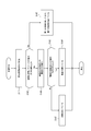
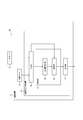
- FIG. 1 is a functional block diagram illustrating a schematic configuration of the imaging system according to the first embodiment.
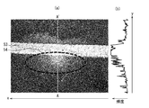
- 2A and 2B are diagrams illustrating an image acquired by the acquisition unit.
- FIG. 2A is a diagram illustrating an example of an image in which a wet road surface is captured
- FIG. 2B is a diagram illustrating FIG. It is a figure which shows the brightness
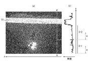
- FIG. 3 is a diagram illustrating another image acquired by the acquisition unit.
- FIG. 3A illustrates an example of an image in which a road surface is captured
- FIG. 3B illustrates FIG. It is a figure which shows the brightness
- FIG. 3 is a diagram illustrating another image acquired by the acquisition unit.
- FIG. 3A illustrates an example of an image in which a road surface is captured
- FIG. 3B illustrates FIG. It is a figure which shows the brightness
- FIG. 4 is a diagram for explaining a non-vibration component of luminance.
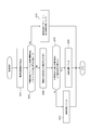
- FIG. 5 is a flowchart illustrating a procedure for determining a road surface state in the first embodiment.
- FIG. 6 is a flowchart showing a detailed procedure of the dry / wet determination process in the first embodiment.
- FIG. 7 is a flowchart showing a detailed procedure of the freezing determination process in the first embodiment.
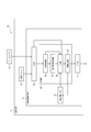
- FIG. 8 is a functional block diagram illustrating a schematic configuration of the imaging system according to the second embodiment.
- FIG. 9 is a flowchart showing a detailed procedure of dry / wet determination processing in the second embodiment.
- FIG. 10 is a functional block diagram illustrating a schematic configuration of an imaging system according to the third embodiment.
- FIG. 11 is a diagram illustrating an image acquired by the acquisition unit.
- FIG. 11A is a diagram illustrating an example of an image in which a dry road surface including a lane marking is captured
- FIG. 12 is a diagram illustrating an image acquired by the acquisition unit.
- FIG. 12A is a diagram illustrating an example of an image in which a wet road surface including a lane marking is captured
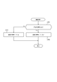
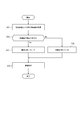
- FIG. 13 is a flowchart illustrating a procedure for determining a road surface state in the third embodiment.
- reflected light of the projected light may be received, and at the same time, external light such as sunlight, illumination light, or light projected by another vehicle may be received.
- external light such as sunlight, illumination light, or light projected by another vehicle.
- not only the reflected light but also the level of the light including the reflected light and the outside light is compared, and there is a possibility that the road surface state cannot be accurately determined.
- the road surface state determination device the imaging device, the imaging system, and the road surface state determination method of the present disclosure, the road surface state can be more accurately determined.
- the imaging system 10 includes an imaging device 11 and a FIR (Far Infrared) camera 12.
- the imaging device 11 includes a visible light camera 13 and a road surface state determination device 14.
- the FIR camera 12 captures infrared rays radiated from the surface of the subject, generates a far-infrared image of the subject, and transmits the far-infrared image of the subject to the road surface state determination device 14 as a signal related to the temperature of the subject, that is, the temperature of the road surface. .
- the FIR camera 12 uses a road surface as a subject.
- the direction in which the FIR camera 12 images the road surface that is the subject is the same as the direction in which the visible light camera 13 images the road surface.
- the imaging range of the FIR camera 12 includes the imaging range of the visible light camera 13. In the following description, the imaging range of the FIR camera 12 and the imaging range of the visible light camera 13 are assumed to be the same.
- the imaging system 10 may acquire a signal related to the temperature of the road surface from a thermometer, a temperature sensor, or the like that measures the temperature of the road surface, instead of including the FIR camera 12.
- a thermometer e.g., a thermometer
- a temperature sensor e.g., a thermometer
- a temperature sensor e.g., a thermometer
- the visible light camera 13 is preferably a CCD camera or a CMOS camera, and in this embodiment, the road surface is imaged as a subject, and a visible image that is an image of the surface of the subject by visible light is generated.
- the direction in which the visible light camera 13 images the road surface that is the subject is arbitrary. In the following description, it is assumed that the visible light camera 13 is attached to the front portion of the vehicle and images a road surface in the direction in which the vehicle travels. Further, in the captured image, as shown in FIG. 2, the description will be made by taking the x-axis in the horizontal direction of the visible image and the y-axis in the direction orthogonal to the x-axis.
- the x-axis corresponds to the left-right direction of the vehicle
- the y-axis corresponds to the traveling direction and the vertical direction of the vehicle.
- the visible light camera 13 a monochrome camera may be used.
- the imaging system 10 can also use a near infrared camera having sensitivity in the near infrared region (NIR) instead of including the visible light camera 13.
- NIR near infrared region
- an arbitrary camera among the visible light camera 13 and the near-infrared camera is simply referred to as “camera”.
- the road surface state determination device 14 determines whether the road surface is wet or dry, that is, whether the road surface is wet or dry, based on a visible image generated by the visible light camera 13 imaging the road surface. Further, the road surface state determination device 14 determines whether or not the road surface is frozen, that is, whether or not the road surface is frozen, based on a far-infrared image generated by imaging the infrared light reflected from the road surface by the FIR camera 12. To do.
- the road surface condition determination device 14 is configured to include functional blocks of an acquisition unit 15, a control unit 16 as a controller, and an output unit 17.
- the acquisition unit 15 is an input interface of the road surface state determination device 14.
- the acquisition unit 15 corresponds to the imaging signal transmission method of the visible light camera 13 and acquires a visible image from the visible light camera 13.
- the acquisition unit 15 also corresponds to the imaging signal transmission method of the FIR camera 12 and acquires a far-infrared image from the FIR camera 12. Further, the acquisition unit 15 delivers the acquired visible image and far-infrared image to the control unit 16.
- the control unit 16 is a part that executes various arithmetic processes of the road surface state determination device 14, and is a general-purpose CPU (Central Processing Unit) that executes processing according to a software program and / or an ASIC (Application that is designed for image processing). Specific (Integrated (Circuit)), FPGA (Field-Programmable Gate Array), and the like can be included.
- the control unit 16 includes functional blocks including a luminance extraction unit 18, a spatial frequency calculation unit 19, and a determination unit 20.
- the luminance extraction unit 18 extracts the luminance of pixels on one line segment (continuous region) in the visible image from the visible image acquired by the visible light camera 13.
- the line segment has one end portion and another end portion of the image parallel to the y-axis direction in the image space of the visible image shown in FIGS. 2 (a) and 3 (a).
- a line segment is not limited to this, and may be, for example, a line segment parallel to the x-axis or a line segment that is oblique to the x-axis.
- the luminance extraction unit 18 may extract the luminance of pixels on a curve or in a plane instead of a line segment.
- the vertical axis represents the length y from the point A of the image
- the horizontal axis represents the pixel luminance.
- the luminance extraction unit 18 calculates a non-vibration component indicating a variation in the overall luminance height from the luminance graph, excluding the luminance vibration component caused by the road surface shape as follows.
- the same brightness that is, the luminance
- the portions of the dividing lines 51 and 52 such as the road center line and the lane boundary line.
- surrounding objects buildings, trees, vehicles, people, etc.
- the sky appear in the wet area of the road surface, as shown in FIG. There is.
- the average luminance height is higher than the average luminance height of the other areas as indicated by the thick line (1) in FIG.
- the average luminance height is lower than the average luminance height of other areas, as indicated by a thick line (2) in FIG. .
- the luminance waveform appearing in the luminance graph has a vibration component due to the spatial frequency caused by the unevenness of the road surface. Therefore, the luminance extraction unit 18 calculates a non-vibration component obtained by removing a vibration component having a cycle shorter than the cycle caused by road surface unevenness from the luminance graph.
- the non-vibration component of the luminance will be described with reference to FIG.
- the broken line in FIG. 4 is an enlarged representation of the luminance value of a part of the portion indicated by 2-2 in FIG.
- the non-vibration component is an average value of luminance values (see L ave in FIG. 4) within a range of one cycle of vibration, as shown in two broken lines.
- a non-vibration component of luminance representing the fluctuation in height is calculated.
- the non-vibration component is calculated in the same manner for portions other than the portion indicated by 2-2 in FIG.
- the luminance extraction unit 18 passes the non-vibration components of these luminances together with the luminance of each pixel on the extracted line segment to the determination unit 20.
- non-vibration component of the luminance described here is an example of an amount representing the height excluding the vibration component of the varying luminance value, and other arbitrary amounts representing the height of the luminance value are used for the subsequent values. Processing may be performed.
- the spatial frequency calculation unit 19 calculates a spatial frequency based on the luminance of the pixel group extracted by the luminance extraction unit 18.
- the road surface is formed so that the surface thereof has fine irregularities so as to have a friction coefficient equal to or greater than a predetermined value. Therefore, there are fine irregularities in the dry area of the road surface, and the luminance is likely to change.
- the luminance distribution on the surface is smooth. Therefore, the spatial frequency of the luminance of the pixel representing the dry road surface area is higher than the spatial frequency for the wet area.
- Spatial frequency is observed as a change in a parameter corresponding to the spatial frequency (hereinafter referred to as “spatial frequency parameter”).
- the spatial frequency parameter is, for example, the number of vibration peaks per unit length when the vibration of the pixel signal is observed on the line segment from which the pixels are extracted.
- the spatial frequency parameter may be the number of times per unit length that the waveform of the pixel signal crosses the non-vibration component of the luminance described above from top to bottom or from bottom to top.
- the road surface is dry in the region indicated by 3-1 on the AA ′ line of the visible image shown in FIG. 3A, and the road surface is wet in the region indicated by 3-2. Therefore, as shown in FIG. 3B, the spatial frequency parameter of the portion indicated by 3-1 is higher than the spatial frequency parameter of the portion indicated by 3-2.
- a portion where spatial frequencies within a predetermined range are continuous (see 3-1 and 3-2 in FIG. 3B). It can be seen that there are two or more. In addition, among the two or more parts, the first region composed of pixels related to the higher spatial frequency parameter is dry, and the second region composed of pixels related to the lower spatial frequency parameter is wet. I understand.
- the spatial frequency calculation unit 19 may convert a spatial region represented by the pixel signal into a spatial frequency region and calculate a frequency that gives a peak value as the spatial frequency. In that case, the calculated spatial frequency itself can be used as a spatial frequency parameter.
- the determination unit 20 performs dry / wet determination processing for determining whether the road surface is dry or wet based on a spatial change in luminance of pixels in a continuous region included in the image.
- the spatial change is a change in the image space of the feature amount related to the image, and the non-vibration component of the luminance of each pixel and the luminance on the line segment acquired from the luminance extraction unit 18 and the space acquired from the spatial frequency calculation unit 19 Frequency parameters and the like.
- the determination unit 20 first determines, based on the spatial frequency parameter calculated by the spatial frequency calculation unit 19, a dry area and a wet area on the road surface represented in the image. The determination process is performed.
- the determination unit 20 extracts frequency continuous portions where the spatial frequency parameters within a predetermined range are continuous by a predetermined number of pixels a or more.
- the predetermined number of pixels a is a value that is expected to be suitable for determining the road surface state when the spatial frequency within a predetermined range is continuous beyond this value. That is, the predetermined number of pixels a is a value that is considered unsuitable for use in determining the road surface condition because noise is included when the spatial frequency is continuous within a range smaller than this value.
- the predetermined number of pixels a may be 10 pixels, but may be set as appropriate.
- the determination part 20 compares the spatial frequency parameter calculated as mentioned above in each of the extracted several frequency continuation part.
- the determination unit 20 determines that the first region (3-1 in FIG. 3A) composed of pixels related to the higher spatial frequency parameter Determined to be dry. Further, the determination unit 20 determines that the second region (3-2 in FIG. 3A) composed of pixels related to the lower spatial frequency parameter is wet.
- the predetermined value is a value that can be regarded as having a dry region and a wet region on the road surface when there is a difference in spatial frequency beyond this value.
- the predetermined value is empirically a difference between a spatial frequency parameter that may be calculated in a dry region and a spatial frequency parameter that may be calculated in a wet region. Minimize.
- the predetermined value may be a value corresponding to 30% of the lower spatial frequency, but may be set as appropriate.
- the determination unit 20 determines whether there is a wet region on the road surface represented in the image based on the non-vibration component of the luminance extracted by the luminance extraction unit 18. 2 determination processing is performed.
- the determination unit 20 has a luminance continuous portion in which the non-vibration components of the luminance of the pixels on the line segment extracted by the luminance extraction unit 18 are continuous within a predetermined range (FIG. 2). (See 2-1 and 2-2 in (b)). And the determination part 20 compares the non-vibration component of the brightness
- the predetermined value is a value that can be considered that there is a wet area on the road surface when there is a difference in the non-vibration component beyond this value.
- the predetermined value may be a value corresponding to 30% of the lower non-vibration component, but may be set as appropriate.
- the determination unit 20 determines that there is a wet region on the road surface represented in the image when the region other than the lane markings 51 and 52 in the image satisfies the following two conditions.
- the first condition is that there are two or more portions (see 2-1 and 2-2 in FIG. 2B) where non-vibration components of luminance are continuous within a predetermined range on one line segment. That's what it means.
- the second condition is that the difference between consecutive non-vibration components is equal to or greater than a predetermined value.
- the determination unit 20 when it is determined whether or not the road surface area represented in the visible image is wet, the determination unit 20 further performs a freeze determination process for determining whether or not the area is frozen. .
- the determination unit 20 determines whether the road surface temperature is equal to or higher than a predetermined temperature based on the far-infrared image generated by the FIR camera 12. Determine whether or not. When it is determined that the road surface temperature is equal to or higher than the predetermined temperature, it is determined that the road surface region is wet and not frozen. When it is determined that the road surface temperature is lower than the predetermined temperature, it is determined that the road surface region is wet and frozen.
- the predetermined temperature is a critical temperature at which the rainwater covering the road surface changes from a liquid to a solid, and is desirably about ⁇ 2 ° C. to 0 ° C.
- the determination unit 20 determines whether the road surface temperature indicated by the far-infrared image is equal to or higher than a predetermined temperature for the road surface area determined to be dry based on the visible image. When it is determined that the temperature is equal to or higher than the predetermined temperature, it is determined that the area of the road surface is dry and not frozen. When it is determined that the temperature is lower than the predetermined temperature, it is determined that the road surface area is dry and frozen.
- the determination unit 20 determines whether or not the temperature of the road surface is equal to or higher than a predetermined temperature. And the determination part 20 determines with the road surface not freezing, when the temperature of a road surface is more than predetermined temperature. The determination unit 20 determines that the road surface is frozen when the temperature of the road surface is lower than a predetermined temperature.
- the control unit 16 performs processing for pixels on the line AA ′, which is one line segment, but in order to perform processing for all pixels in a predetermined range on the image. , AA ′ line is sequentially shifted, and the same processing is performed each time.
- the predetermined range on the image is a continuous region in which the road surface state is determined by the control unit 16 based on the spatial change of the luminance of the pixel.
- the control unit 16 may perform processing at arbitrary intervals for pixels in a predetermined range on the image. In this case, the control unit 16 performs processing by shifting the AA ′ line at arbitrary intervals.
- the interval of shifting the AA ′ line is such that the closer to the vehicle on which the visible light camera 13 and the FIR camera 12 are mounted when the direction of the AA ′ line is the x direction, that is, the lateral direction of the vehicle in real space. It may be narrowed. This is because the vehicle or the driver can obtain information for the latest driving by determining the road surface state with higher accuracy in a nearby region than in the far region of the traveling road surface.
- the road surface condition determination device 14 may acquire a signal representing temperature from a thermometer or a temperature sensor instead of acquiring a far-infrared image from the FIR camera 12. In this case, it is determined whether or not the road surface is frozen as described above based on the temperature of the road surface acquired by the thermometer or the temperature sensor.
- the output unit 17 is an output interface of the road surface state determination device 14.
- the output unit 17 outputs the road surface state determined by the control unit 16 to a display device, a vehicle control device, or the like connected to the road surface state determination device 14.
- the acquisition unit 15 acquires a visible image obtained by imaging the road surface from the visible light camera 13, and acquires a far-red line image obtained by imaging infrared rays emitted from the road surface from the FIR camera 12 (step S11).
- the luminance extracting unit 18 extracts the luminance of the pixel on one line segment in the visible image (step S12). Then, the spatial frequency calculation unit 19 calculates a spatial frequency parameter for the luminance of the pixels on the line segment extracted by the luminance extraction unit 18 (step S13).
- the determination unit 20 performs dry / wet determination processing based on the spatial frequency parameter calculated by the spatial frequency calculation unit 19 (step S14).
- the determination unit 20 extracts a frequency continuous portion in which a spatial frequency parameter within a predetermined range continues for a predetermined number of pixels a or more. (Step S141). Then, the determination unit 20 determines whether or not the difference between the spatial frequency parameters in each of the plurality of continuous frequency portions extracted in step S141 is greater than or equal to a predetermined value (step S142).
- the determination unit 20 determines that the first region including the pixels related to the higher spatial frequency parameter is dry and the lower space It determines with the 2nd area
- the determination unit 20 performs the second determination process of the wet and dry determination process.
- the determination unit 20 extracts a luminance continuous portion extracted by the luminance extraction unit 18 in which the non-vibration components of the luminance of the pixels on the line segment are continuous within a predetermined range (Ste S144).
- the determination part 20 determines whether the difference of the non-vibration component of each extracted brightness
- the determination unit 20 determines that the road surface represented in the image is dry (step S147).
- the determination unit 20 performs a freezing determination process for determining whether or not the road surface area determined to be wet or dry in Step S ⁇ b> 14 is frozen (Step S ⁇ b> 14). S15).
- the determination unit 20 determines that the temperature of the far-infrared image generated by the FIR camera 12 is equal to or higher than a predetermined temperature for the road surface area determined to be wet. Whether or not (step S151). When it is determined that the temperature is equal to or higher than the predetermined temperature, the determination unit 20 determines that the road surface area is wet and not frozen (step S152). If it is determined that the temperature is lower than the predetermined temperature, it is determined that the road area is wet and frozen (step S153).
- the determination unit 20 performs the process of step S151 on a dry road surface area.
- the determination part 20 determines with the area
- the determination unit 20 performs a freezing determination process for determining whether or not the road surface on which it is determined whether or not at least a part is wet is also frozen (step S15).
- This freeze determination process is the same as the above-described determination process, and detailed description thereof is omitted.
- the determination unit 20 determines the state of the road surface, specifically, whether the road surface is wet, based on the luminance of the pixels included in the visible image. To do. Unlike the conventional method of projecting light from a vehicle and using the reflected light to determine the road surface condition, this method avoids problems such as being unable to make an accurate determination due to the influence of external light. it can. Therefore, it is possible to accurately determine the road surface state.
- the determination unit 20 determines a wet area and a dry area on the road surface based on a spatial frequency parameter related to the spatial frequency of the brightness. For this reason, the brightness distribution tends to change because there are fine irregularities, that is, it is a dry region having the characteristic that the spatial frequency parameter is high, or because there is rainwater covering the surface of the road surface, the luminance distribution on the surface is Whether the area is smooth, that is, a wet area having a low spatial frequency parameter, can be determined based on a quantitative index using characteristics of an image representing a road surface.
- luminance continuous portions where the non-vibration components of the luminance of the pixels on the extracted line segment are continuous within a predetermined range are extracted, and a plurality of luminance continuous portions are compared.
- the image in order to determine whether or not the image is frozen based on the far-infrared image, not only the wet and dry state of the road surface, but also the dry and wet areas of the road surface. You can know whether each is frozen. Therefore, by outputting this information to a vehicle control system or the like, for example, when a vehicle or the like passes through a wet and frozen area rather than just a wet area, it is more strongly alerted. Can assist driving to prevent slipping.
- the imaging system 30 in the second embodiment includes an imaging device 11 and an FIR camera 12 in the same manner as the imaging system 10 in the first embodiment.
- the imaging device 11 includes a visible light camera 13 and a road surface state determination device 14.
- the road surface state determination device 14 includes functional blocks of an acquisition unit 15, a road surface state memory 31, a control unit 16, and an output unit 17.
- the road surface state memory 31 includes a rewritable memory for storing reference luminance and reference spatial frequency parameters.
- the reference luminance is an image obtained by imaging an image of a road surface on which the imaging device 11 determines whether or not the control unit 16 is wet, that is, a pixel constituting an image captured in a certain period immediately before the control unit 16 performs determination. Is the most frequently occurring luminance. It is assumed that this reference luminance is the luminance of a pixel representing a dry road surface on the assumption that most of the road surface is dry and some are wet.
- the reference spatial frequency parameter is a spatial frequency parameter having the highest appearance frequency among the spatial frequency parameters of an image obtained by imaging the road surface on which the imaging device 11 determines whether the control unit 16 is wet.
- the image obtained by capturing the road surface for determining whether or not the control unit 16 is wet is an image captured for a certain period immediately before the control unit 16 performs the determination. It is assumed that the reference spatial frequency parameter is a spatial frequency parameter of a dry area on the road surface on the assumption that most of the road surface is dry and some of the road surface is wet.
- a non-volatile memory such as a flash memory, a magnetoresistive memory (MRAM (MagnetoresistiveesisRandom Access Memory)), a ferroelectric memory (FeRAM (Ferroelectric Random Access Memory)), or the like is used. it can.
- MRAM Magnetoresistive memory
- FeRAM Feroelectric Random Access Memory
- the control unit 16 includes a luminance extraction unit 18, a spatial frequency calculation unit 19, a determination unit 32, and a reference update unit 33.
- the process of the determination unit 32 is different from the process of the determination unit 20 in the first embodiment.
- the determination unit 32 is a frequency continuous portion calculated by the spatial frequency calculation unit 19 and in which the spatial frequency parameter within a predetermined range continues for a predetermined number of pixels a (see 3-1 and 3-2 in FIG. 3). ). Then, the determination unit 32 compares the extracted spatial frequency parameter in the continuous frequency portion with the reference spatial frequency parameter stored in the road surface state memory 31.
- the determination unit 32 determines that the road surface region corresponding to the frequency continuous portion is wet. In addition, when the difference between the spatial frequency parameter and the reference spatial frequency parameter is less than a predetermined value, the determination unit 32 performs determination based on luminance as will be described later for the road surface area represented in the image.
- the determination unit 32 extracts a luminance continuous portion in which the luminance non-vibration components of the pixels on the AA ′ line extracted by the luminance extraction unit 18 are continuous within a predetermined range. Then, the determination unit 32 compares the luminance non-vibration component in the extracted luminance continuous portion with the reference non-vibration component stored in the road surface state memory 31. Further, when the difference between the luminance non-vibration component and the reference non-vibration component is equal to or greater than a predetermined value, the determination unit 32 determines that the road surface area corresponding to the luminance continuous portion is wet.
- the determination part 32 determines with the area
- the determination unit 32 performs a freezing determination process for determining whether or not the road surface is frozen when the wet and dry state of the road surface is determined.
- the freezing determination process performed by the determination unit 32 is the same as the freezing determination process performed by the determination unit 20 of the first embodiment, and thus detailed description thereof is omitted.
- the reference updating unit 33 uses the imaging device 11 in the road surface state memory 31 as the reference luminance with the highest appearance frequency among the luminances of the pixels constituting the image captured during a certain period while traveling on the same road.
- the reference update unit 33 uses the spatial frequency parameter with the highest appearance frequency among the spatial frequency parameters calculated from images captured by the imaging device 11 traveling on the same road for a certain period as the reference spatial frequency parameter. Is stored in the road surface state memory 31.
- the road surface state determination method of the road surface state determination device 14 according to the second embodiment is substantially the same as the road surface state determination method of the road surface state determination device 14 according to the first embodiment, but the wet and dry determination processing is different. Next, the dry / wet determination process in the second embodiment will be described.
- the determination unit 32 extracts a continuous frequency portion where the spatial frequency parameter within a predetermined range continues for a predetermined number of pixels a or more (step S ⁇ b> 241). Then, the determination unit 32 determines whether or not the difference between the spatial frequency parameter and the reference spatial frequency parameter in the plurality of frequency continuous portions extracted in step S241 is equal to or greater than a predetermined value (step S242).
- step S242 determines that the region composed of pixels related to the spatial frequency parameter is wet (step S243). ).
- step S242 when the difference between the spatial frequency parameter and the reference spatial frequency parameter is less than a predetermined value, a second determination process is performed.
- the determination unit 32 extracts a luminance continuous portion extracted by the luminance extraction unit 18 in which the non-vibration components of the luminance of the pixels on the line segment are continuous within a predetermined range (Ste S244). Then, the determination unit 20 determines whether or not the difference between the luminance non-vibration component and the reference non-vibration component in the extracted luminance continuous portion is equal to or greater than a predetermined value (step S245). If the difference between the luminance non-vibration component and the reference non-vibration component is equal to or greater than a predetermined value, it is determined that the road surface is wet (step S246).
- the determination unit 32 determines that the road surface is dry (step S247).
- the determination unit 32 determines the road surface state based on the reference spatial frequency parameter regarded as the spatial frequency parameter of the dry region.
- the reference spatial frequency parameter is a spatial frequency parameter having the highest appearance frequency among the spatial frequency parameters of images captured during a certain period of traveling on the same road. Therefore, most of the road surface is dry, and for a road surface having a wet part, the dry area of the road surface can be accurately determined.
- the imaging system 40 in the third embodiment includes an imaging device 11 and an FIR camera 12 in the same manner as the imaging system 10 in the first embodiment.
- the imaging device 11 includes a visible light camera 13 and a road surface state determination device 14.
- the road surface state determination device 14 is configured to include functional blocks of an acquisition unit 15, a control unit 16, and an output unit 17.
- the process of the control part 16 differs from the control part 16 in 1st Embodiment.
- the control unit 16 includes a lane marking detection unit 41 and a determination unit 42.
- the lane line detection unit 41 determines whether or not the lane line 53 (see FIG. 11) can be extracted from the visible image acquired by the acquisition unit 15.
- the relationship between the road surface condition and whether or not the lane marking is detected will be described in detail.
- the lane markings 53 displayed on the road surface are white or the like. Therefore, as shown in FIG. 11B, the luminance of the pixel indicated by 10-1 corresponding to the partition line 53 is high.
- the pixel value between the pixel representing the lane marking 53 and the pixel representing the road excluding the lane marking 53 is greater than a predetermined value, the pixel corresponding to the end of the lane marking 53 is detected as an edge.
- the approximate straight line of the extracted edge group can be detected as the partition line 53.
- the lane marking detection unit 41 performs a process for detecting the lane marking 53 using a known lane marking detection method based on the visible image, and determines whether the lane marking 53 can be detected.
- the lane marking detection unit 41 is a known method for detecting an edge corresponding to an end of one lane marking 53 represented in a predetermined region of interest in the image acquired by the acquisition unit 15. Perform the process. As a result, when two sets of edge groups each approximated by two straight lines are detected and the distance between the two straight lines is a distance corresponding to the width of the lane marking 53, the lane marking detection unit 41 outputs a detection result that the lane marking 53 can be detected. In addition, when no edge is detected, the lane line detection unit 41 outputs a detection result that the lane line 53 cannot be detected.
- the determination unit 42 determines that the road surface shown in the image is wet when a detection result indicating that the lane marking 53 cannot be detected is output. Moreover, the determination part 42 will determine with the road surface represented by the image being dry, if the detection result that detection of the lane marking 53 is possible is output.
- the determination unit 42 determines whether the road surface shown in the image is wet or dry and then determines whether the road surface is frozen, as in the determination unit 20 of the first embodiment. Freeze determination processing is performed. Since the freezing determination process by the determination unit 42 is the same as the freezing determination process by the determination unit 20 of the first embodiment, detailed description thereof is omitted.
- the acquisition unit 15 acquires a visible image obtained by imaging the road surface from the visible light camera 13 and a far-infrared image obtained by imaging infrared rays emitted from the road surface from the FIR camera 12 (step S31).
- the lane marking detection unit 41 When a visible image is generated in step S31, the lane marking detection unit 41 performs lane marking detection using a known lane marking detection method based on the visible image. A detection result indicating availability is output (step S32).
- step S32 determines that the road surface represented in the image is dry (step S33). If a detection result indicating that the lane marking 53 cannot be detected is output in step S32, the determination unit 42 determines that the road surface represented in the image is wet (step S34).
- the determination unit 20 performs a freeze determination process for determining whether or not the road surface determined to be dry in Step S33 and the road surface determined to be wet in Step S34 are frozen (Step S33). S35). Thereby, the determination unit 20 can determine whether the road surface is dry and frozen, whether it is dry and not frozen, wet and frozen, or wet and not frozen. it can.
- the freezing determination process in step S35 is the same as the freezing determination process of the first embodiment, and a detailed description thereof is omitted here.
- the road surface state determination device 14 performs the process for detecting the lane marking 53, and when the lane marking 53 can be detected, the road surface is dry. If the lane marking 53 cannot be detected, it is determined that the road surface is wet. As described above, since the determination is made based on the lane markings 53 stipulated by laws and regulations, the road surface state can be accurately determined on the road on which the lane markings 53 are marked.
- the imaging system 10 of the fourth embodiment includes an imaging device 11 and an FIR (Far Infrared) camera 12 as shown in FIG. Composed.
- the imaging device 11 includes a visible light camera 13 and a road surface state determination device 14.
- the road surface state determination device 14 according to the fourth embodiment is similar to the road surface state determination device 14 in the road surface state determination device 14 according to the first embodiment.
- the control part 16 of 4th Embodiment contains each functional block of the brightness
- the determination unit 20 of the first embodiment determines whether or not the region determined to be dry and the region determined to be wet are frozen. In the fourth embodiment, the determination unit 20 determines whether or not one or more of an area determined to be dry and an area determined to be wet are frozen.
- the determination unit 20 performs the freeze determination process after the dry / wet determination process, but it is not necessary to perform only the dry / humidity determination process and perform the freeze determination process.
- Imaging system 11 Imaging device 12
- FIR camera 13 Visible light camera 14
- Road surface state determination device 15 Acquisition unit 16
- Control unit 17 Output unit 18
- Luminance extraction unit 19 Spatial frequency calculation unit 20, 32, 42 Determination unit 31 Road surface state Memory 41 Marking line detector 51, 52, 53 Marking line
Landscapes
- Engineering & Computer Science (AREA)
- Physics & Mathematics (AREA)
- General Physics & Mathematics (AREA)
- Multimedia (AREA)
- Theoretical Computer Science (AREA)
- Computer Vision & Pattern Recognition (AREA)
- Immunology (AREA)
- General Health & Medical Sciences (AREA)
- Analytical Chemistry (AREA)
- Pathology (AREA)
- Life Sciences & Earth Sciences (AREA)
- Biochemistry (AREA)
- Chemical & Material Sciences (AREA)
- Health & Medical Sciences (AREA)
- Mechanical Engineering (AREA)
- Transportation (AREA)
- Mathematical Physics (AREA)
- Automation & Control Theory (AREA)
- Traffic Control Systems (AREA)
- Image Analysis (AREA)
- Investigating Or Analysing Materials By Optical Means (AREA)
Priority Applications (3)
| Application Number | Priority Date | Filing Date | Title |
|---|---|---|---|
| US15/769,573 US10501088B2 (en) | 2015-10-22 | 2016-08-29 | Road surface state determination apparatus, imaging apparatus, imaging system, and road surface state determination method |
| EP16857067.9A EP3367084B1 (de) | 2015-10-22 | 2016-08-29 | Vorrichtung und verfahren zur bestimmung des strassenflächenzustands |
| JP2017546389A JP6582055B2 (ja) | 2015-10-22 | 2016-08-29 | 路面状態判定装置、撮像装置、撮像システムおよび路面状態判定方法 |
Applications Claiming Priority (2)
| Application Number | Priority Date | Filing Date | Title |
|---|---|---|---|
| JP2015-208243 | 2015-10-22 | ||
| JP2015208243 | 2015-10-22 |
Publications (1)
| Publication Number | Publication Date |
|---|---|
| WO2017068743A1 true WO2017068743A1 (ja) | 2017-04-27 |
Family
ID=58556815
Family Applications (1)
| Application Number | Title | Priority Date | Filing Date |
|---|---|---|---|
| PCT/JP2016/003929 Ceased WO2017068743A1 (ja) | 2015-10-22 | 2016-08-29 | 路面状態判定装置、撮像装置、撮像システムおよび路面状態判定方法 |
Country Status (4)
| Country | Link |
|---|---|
| US (1) | US10501088B2 (de) |
| EP (1) | EP3367084B1 (de) |
| JP (1) | JP6582055B2 (de) |
| WO (1) | WO2017068743A1 (de) |
Cited By (7)
| Publication number | Priority date | Publication date | Assignee | Title |
|---|---|---|---|---|
| US10706294B2 (en) | 2018-05-03 | 2020-07-07 | Volvo Car Corporation | Methods and systems for generating and using a road friction estimate based on camera image signal processing |
| US10773725B1 (en) * | 2017-08-25 | 2020-09-15 | Apple Inc. | Tire-road friction estimation and mapping |
| US11124193B2 (en) | 2018-05-03 | 2021-09-21 | Volvo Car Corporation | System and method for providing vehicle safety distance and speed alerts under slippery road conditions |
| JP2022026042A (ja) * | 2020-07-30 | 2022-02-10 | 株式会社リコー | 情報処理装置、情報処理システム、情報処理方法およびプログラム |
| US11592566B2 (en) | 2019-08-15 | 2023-02-28 | Volvo Car Corporation | Vehicle systems and methods utilizing LIDAR data for road condition estimation |
| JP2023524992A (ja) * | 2020-05-04 | 2023-06-14 | ティモシー・ジャスト | 予測車両動作支援 |
| JP2024040765A (ja) * | 2022-09-13 | 2024-03-26 | 株式会社日本線路技術 | 情報処理装置、情報処理方法及び情報処理プログラム |
Families Citing this family (13)
| Publication number | Priority date | Publication date | Assignee | Title |
|---|---|---|---|---|
| US10233679B1 (en) | 2016-04-11 | 2019-03-19 | State Farm Mutual Automobile Insurance Company | Systems and methods for control systems to facilitate situational awareness of a vehicle |
| US10872379B1 (en) | 2016-04-11 | 2020-12-22 | State Farm Mutual Automobile Insurance Company | Collision risk-based engagement and disengagement of autonomous control of a vehicle |
| US10222228B1 (en) | 2016-04-11 | 2019-03-05 | State Farm Mutual Automobile Insurance Company | System for driver's education |
| US11851041B1 (en) * | 2016-04-11 | 2023-12-26 | State Farm Mutual Automobile Insurance Company | System for determining road slipperiness in bad weather conditions |
| US10019904B1 (en) | 2016-04-11 | 2018-07-10 | State Farm Mutual Automobile Insurance Company | System for identifying high risk parking lots |
| US10247565B2 (en) | 2016-04-11 | 2019-04-02 | State Farm Mutual Automobile Insurance Company | Traffic risk avoidance for a route selection system |
| US10486708B1 (en) | 2016-04-11 | 2019-11-26 | State Farm Mutual Automobile Insurance Company | System for adjusting autonomous vehicle driving behavior to mimic that of neighboring/surrounding vehicles |
| US10026309B1 (en) | 2016-04-11 | 2018-07-17 | State Farm Mutual Automobile Insurance Company | Networked vehicle control systems to facilitate situational awareness of vehicles |
| CN108629231B (zh) * | 2017-03-16 | 2021-01-22 | 百度在线网络技术(北京)有限公司 | 障碍物检测方法、装置、设备及存储介质 |
| WO2020158262A1 (ja) * | 2019-01-30 | 2020-08-06 | 日本電気株式会社 | 劣化診断装置、劣化診断システム、劣化診断方法、記録媒体 |
| US11645844B2 (en) * | 2021-10-05 | 2023-05-09 | RS1 Worklete, LLC | Computing devices programmed to detect slippery surfaces within enclosures and methods/systems of used thereof |
| CN114125451B (zh) * | 2021-12-01 | 2022-12-06 | 锐宸微(上海)科技有限公司 | 视频编码方法、视频编码装置及影像处理装置 |
| CN115082701B (zh) * | 2022-08-16 | 2022-11-08 | 山东高速集团有限公司创新研究院 | 一种基于双摄像头的多水线交叉识别定位方法 |
Citations (3)
| Publication number | Priority date | Publication date | Assignee | Title |
|---|---|---|---|---|
| JPH02161337A (ja) * | 1988-12-14 | 1990-06-21 | Nagoya Denki Kogyo Kk | 路面状態検知装置 |
| JPH10221043A (ja) * | 1996-12-02 | 1998-08-21 | Omron Corp | 路面状態判別装置 |
| JP2002286862A (ja) * | 2001-03-23 | 2002-10-03 | Nagoya Electric Works Co Ltd | 路面状態判別方法およびその装置 |
Family Cites Families (10)
| Publication number | Priority date | Publication date | Assignee | Title |
|---|---|---|---|---|
| JPH0221043A (ja) * | 1988-07-08 | 1990-01-24 | Nippon Denso Co Ltd | 減衰力可変ショックアブソーバ |
| JPH08247940A (ja) | 1995-03-14 | 1996-09-27 | Honda Motor Co Ltd | 路面状態検知装置 |
| JPH08263784A (ja) * | 1995-03-23 | 1996-10-11 | Honda Motor Co Ltd | 道路状況認識装置 |
| FR2826727B1 (fr) | 2001-06-29 | 2004-05-28 | Valeo Vision | Procede et dispositif pour detecter l'etat d'humidite d'une route sur laquelle circule un vehicule |
| JP4011505B2 (ja) | 2003-03-17 | 2007-11-21 | 名古屋電機工業株式会社 | 路面状態検出装置、路面状態検出方法および路面状態検出プログラム |
| JP4939137B2 (ja) * | 2006-07-19 | 2012-05-23 | 富士重工業株式会社 | 車線認識装置 |
| JP5089448B2 (ja) | 2008-03-14 | 2012-12-05 | 富士通株式会社 | 反射特性評価装置、反射特性評価方法および反射特性評価プログラム |
| JP5457224B2 (ja) * | 2010-02-24 | 2014-04-02 | 国立大学法人九州工業大学 | 路面状態検出装置 |
| JP5648546B2 (ja) | 2011-03-17 | 2015-01-07 | 株式会社Ihi | 通路検出装置、方法、及びプログラム |
| JP5893601B2 (ja) * | 2013-10-31 | 2016-03-23 | 富士重工業株式会社 | 車両制御システム |
-
2016
- 2016-08-29 EP EP16857067.9A patent/EP3367084B1/de active Active
- 2016-08-29 WO PCT/JP2016/003929 patent/WO2017068743A1/ja not_active Ceased
- 2016-08-29 JP JP2017546389A patent/JP6582055B2/ja active Active
- 2016-08-29 US US15/769,573 patent/US10501088B2/en active Active
Patent Citations (3)
| Publication number | Priority date | Publication date | Assignee | Title |
|---|---|---|---|---|
| JPH02161337A (ja) * | 1988-12-14 | 1990-06-21 | Nagoya Denki Kogyo Kk | 路面状態検知装置 |
| JPH10221043A (ja) * | 1996-12-02 | 1998-08-21 | Omron Corp | 路面状態判別装置 |
| JP2002286862A (ja) * | 2001-03-23 | 2002-10-03 | Nagoya Electric Works Co Ltd | 路面状態判別方法およびその装置 |
Cited By (11)
| Publication number | Priority date | Publication date | Assignee | Title |
|---|---|---|---|---|
| US10773725B1 (en) * | 2017-08-25 | 2020-09-15 | Apple Inc. | Tire-road friction estimation and mapping |
| US10706294B2 (en) | 2018-05-03 | 2020-07-07 | Volvo Car Corporation | Methods and systems for generating and using a road friction estimate based on camera image signal processing |
| US11124193B2 (en) | 2018-05-03 | 2021-09-21 | Volvo Car Corporation | System and method for providing vehicle safety distance and speed alerts under slippery road conditions |
| US11164013B2 (en) | 2018-05-03 | 2021-11-02 | Volvo Car Corporation | Methods and systems for generating and using a road friction estimate based on camera image signal processing |
| US11628844B2 (en) | 2018-05-03 | 2023-04-18 | Volvo Car Corporation | System and method for providing vehicle safety distance and speed alerts under slippery road conditions |
| US11884279B2 (en) | 2018-05-03 | 2024-01-30 | Volvo Car Corporation | System and method for providing vehicle safety distance and speed alerts under slippery road conditions |
| US11592566B2 (en) | 2019-08-15 | 2023-02-28 | Volvo Car Corporation | Vehicle systems and methods utilizing LIDAR data for road condition estimation |
| JP2023524992A (ja) * | 2020-05-04 | 2023-06-14 | ティモシー・ジャスト | 予測車両動作支援 |
| JP2022026042A (ja) * | 2020-07-30 | 2022-02-10 | 株式会社リコー | 情報処理装置、情報処理システム、情報処理方法およびプログラム |
| JP7439684B2 (ja) | 2020-07-30 | 2024-02-28 | 株式会社リコー | 情報処理装置、情報処理システム、情報処理方法およびプログラム |
| JP2024040765A (ja) * | 2022-09-13 | 2024-03-26 | 株式会社日本線路技術 | 情報処理装置、情報処理方法及び情報処理プログラム |
Also Published As
| Publication number | Publication date |
|---|---|
| EP3367084A4 (de) | 2019-05-08 |
| US20180304898A1 (en) | 2018-10-25 |
| JP6582055B2 (ja) | 2019-09-25 |
| EP3367084A9 (de) | 2018-11-07 |
| JPWO2017068743A1 (ja) | 2018-07-12 |
| EP3367084B1 (de) | 2023-09-06 |
| US10501088B2 (en) | 2019-12-10 |
| EP3367084A1 (de) | 2018-08-29 |
Similar Documents
| Publication | Publication Date | Title |
|---|---|---|
| JP6582055B2 (ja) | 路面状態判定装置、撮像装置、撮像システムおよび路面状態判定方法 | |
| JP4359710B2 (ja) | 車両周辺監視装置、車両、車両周辺監視用プログラム、車両周辺監視方法 | |
| KR101411668B1 (ko) | 교정 장치, 거리 측정 시스템, 교정 방법, 및 교정 프로그램을 기록한 컴퓨터 판독 가능한 기록 매체 | |
| JP5809751B2 (ja) | 対象物認識装置 | |
| US9424462B2 (en) | Object detection device and object detection method | |
| CN113099120B (zh) | 深度信息获取方法、装置、可读存储介质及深度相机 | |
| JP4263737B2 (ja) | 歩行者検知装置 | |
| JP2014215877A (ja) | 物体検出装置 | |
| JPWO2021193148A5 (ja) | 道路劣化診断装置、道路劣化診断システム、道路劣化診断方法、及び、プログラム | |
| WO2010047015A1 (ja) | 車両周辺監視装置 | |
| JP7485011B2 (ja) | 道路劣化診断装置、道路劣化診断システム、道路劣化診断方法、及び、プログラム | |
| CN107527017B (zh) | 停车位检测方法及系统、存储介质及电子设备 | |
| JP2011227029A (ja) | 車両の周辺監視装置 | |
| KR20210005605A (ko) | 카메라 고유 파라미터에 대한 온라인 평가 | |
| JP6462557B2 (ja) | 車両ピッチ角推定装置 | |
| JP7043787B2 (ja) | 対象物検知システム | |
| JP3807583B2 (ja) | 道路領域判定装置 | |
| JP6970568B2 (ja) | 車両の周辺監視装置と周辺監視方法 | |
| JP7648669B2 (ja) | システム | |
| JP5172887B2 (ja) | 車両の周辺監視装置 | |
| JP2020095619A (ja) | 画像処理装置および画像処理方法 | |
| JP6719328B2 (ja) | 車外監視装置 | |
| JP6429101B2 (ja) | 画像判定装置、画像処理装置、画像判定プログラム、画像判定方法、移動体 | |
| JP2014135612A (ja) | カメラ露出設定装置及びカメラ露出設定プログラム | |
| JP2004317309A (ja) | 視程算定システム及びそのプログラム |
Legal Events
| Date | Code | Title | Description |
|---|---|---|---|
| 121 | Ep: the epo has been informed by wipo that ep was designated in this application |
Ref document number: 16857067 Country of ref document: EP Kind code of ref document: A1 |
|
| ENP | Entry into the national phase |
Ref document number: 2017546389 Country of ref document: JP Kind code of ref document: A |
|
| WWE | Wipo information: entry into national phase |
Ref document number: 15769573 Country of ref document: US |
|
| NENP | Non-entry into the national phase |
Ref country code: DE |
|
| WWE | Wipo information: entry into national phase |
Ref document number: 2016857067 Country of ref document: EP |