WO2017086099A1 - 電圧・無効電力制御装置、方法、および電圧・無効電力制御システム - Google Patents
電圧・無効電力制御装置、方法、および電圧・無効電力制御システム Download PDFInfo
- Publication number
- WO2017086099A1 WO2017086099A1 PCT/JP2016/081530 JP2016081530W WO2017086099A1 WO 2017086099 A1 WO2017086099 A1 WO 2017086099A1 JP 2016081530 W JP2016081530 W JP 2016081530W WO 2017086099 A1 WO2017086099 A1 WO 2017086099A1
- Authority
- WO
- WIPO (PCT)
- Prior art keywords
- voltage
- reactive power
- control
- control device
- target value
- Prior art date
- Legal status (The legal status is an assumption and is not a legal conclusion. Google has not performed a legal analysis and makes no representation as to the accuracy of the status listed.)
- Ceased
Links
Images






Classifications
-
- H—ELECTRICITY
- H02—GENERATION; CONVERSION OR DISTRIBUTION OF ELECTRIC POWER
- H02J—ELECTRIC POWER NETWORKS; CIRCUIT ARRANGEMENTS OR SYSTEMS FOR SUPPLYING OR DISTRIBUTING ELECTRIC POWER; SYSTEMS FOR STORING ELECTRIC ENERGY
- H02J3/00—Circuit arrangements for AC mains or AC distribution networks
- H02J3/18—Arrangements for adjusting, eliminating or compensating reactive power in networks
-
- G—PHYSICS
- G05—CONTROLLING; REGULATING
- G05B—CONTROL OR REGULATING SYSTEMS IN GENERAL; FUNCTIONAL ELEMENTS OF SUCH SYSTEMS; MONITORING OR TESTING ARRANGEMENTS FOR SUCH SYSTEMS OR ELEMENTS
- G05B13/00—Adaptive control systems, i.e. systems automatically adjusting themselves to have a performance which is optimum according to some preassigned criterion
- G05B13/02—Adaptive control systems, i.e. systems automatically adjusting themselves to have a performance which is optimum according to some preassigned criterion electric
- G05B13/04—Adaptive control systems, i.e. systems automatically adjusting themselves to have a performance which is optimum according to some preassigned criterion electric involving the use of models or simulators
- G05B13/041—Adaptive control systems, i.e. systems automatically adjusting themselves to have a performance which is optimum according to some preassigned criterion electric involving the use of models or simulators in which a variable is automatically adjusted to optimise the performance
-
- H—ELECTRICITY
- H02—GENERATION; CONVERSION OR DISTRIBUTION OF ELECTRIC POWER
- H02J—ELECTRIC POWER NETWORKS; CIRCUIT ARRANGEMENTS OR SYSTEMS FOR SUPPLYING OR DISTRIBUTING ELECTRIC POWER; SYSTEMS FOR STORING ELECTRIC ENERGY
- H02J13/00—Circuit arrangements for providing remote monitoring or remote control of equipment in a power distribution network
-
- H—ELECTRICITY
- H02—GENERATION; CONVERSION OR DISTRIBUTION OF ELECTRIC POWER
- H02J—ELECTRIC POWER NETWORKS; CIRCUIT ARRANGEMENTS OR SYSTEMS FOR SUPPLYING OR DISTRIBUTING ELECTRIC POWER; SYSTEMS FOR STORING ELECTRIC ENERGY
- H02J13/00—Circuit arrangements for providing remote monitoring or remote control of equipment in a power distribution network
- H02J13/13—Circuit arrangements for providing remote monitoring or remote control of equipment in a power distribution network characterised by the transmission of data to equipment in the power network
- H02J13/1311—Circuit arrangements for providing remote monitoring or remote control of equipment in a power distribution network characterised by the transmission of data to equipment in the power network using the power network as support for the transmission
-
- H—ELECTRICITY
- H02—GENERATION; CONVERSION OR DISTRIBUTION OF ELECTRIC POWER
- H02J—ELECTRIC POWER NETWORKS; CIRCUIT ARRANGEMENTS OR SYSTEMS FOR SUPPLYING OR DISTRIBUTING ELECTRIC POWER; SYSTEMS FOR STORING ELECTRIC ENERGY
- H02J3/00—Circuit arrangements for AC mains or AC distribution networks
-
- H—ELECTRICITY
- H02—GENERATION; CONVERSION OR DISTRIBUTION OF ELECTRIC POWER
- H02J—ELECTRIC POWER NETWORKS; CIRCUIT ARRANGEMENTS OR SYSTEMS FOR SUPPLYING OR DISTRIBUTING ELECTRIC POWER; SYSTEMS FOR STORING ELECTRIC ENERGY
- H02J3/00—Circuit arrangements for AC mains or AC distribution networks
- H02J3/12—Arrangements for adjusting voltage in AC networks by changing a characteristic of the network load
-
- H—ELECTRICITY
- H02—GENERATION; CONVERSION OR DISTRIBUTION OF ELECTRIC POWER
- H02J—ELECTRIC POWER NETWORKS; CIRCUIT ARRANGEMENTS OR SYSTEMS FOR SUPPLYING OR DISTRIBUTING ELECTRIC POWER; SYSTEMS FOR STORING ELECTRIC ENERGY
- H02J3/00—Circuit arrangements for AC mains or AC distribution networks
- H02J3/38—Arrangements for feeding a single network from two or more generators or sources in parallel; Arrangements for feeding already energised networks from additional generators or sources in parallel
- H02J3/381—Dispersed generators
-
- H—ELECTRICITY
- H02—GENERATION; CONVERSION OR DISTRIBUTION OF ELECTRIC POWER
- H02J—ELECTRIC POWER NETWORKS; CIRCUIT ARRANGEMENTS OR SYSTEMS FOR SUPPLYING OR DISTRIBUTING ELECTRIC POWER; SYSTEMS FOR STORING ELECTRIC ENERGY
- H02J3/00—Circuit arrangements for AC mains or AC distribution networks
- H02J3/38—Arrangements for feeding a single network from two or more generators or sources in parallel; Arrangements for feeding already energised networks from additional generators or sources in parallel
- H02J3/46—Controlling the sharing of generated power between the generators, sources or networks
- H02J3/48—Controlling the sharing of active power
-
- H—ELECTRICITY
- H02—GENERATION; CONVERSION OR DISTRIBUTION OF ELECTRIC POWER
- H02J—ELECTRIC POWER NETWORKS; CIRCUIT ARRANGEMENTS OR SYSTEMS FOR SUPPLYING OR DISTRIBUTING ELECTRIC POWER; SYSTEMS FOR STORING ELECTRIC ENERGY
- H02J3/00—Circuit arrangements for AC mains or AC distribution networks
- H02J3/38—Arrangements for feeding a single network from two or more generators or sources in parallel; Arrangements for feeding already energised networks from additional generators or sources in parallel
- H02J3/46—Controlling the sharing of generated power between the generators, sources or networks
- H02J3/50—Controlling the sharing of reactive power
-
- H—ELECTRICITY
- H02—GENERATION; CONVERSION OR DISTRIBUTION OF ELECTRIC POWER
- H02J—ELECTRIC POWER NETWORKS; CIRCUIT ARRANGEMENTS OR SYSTEMS FOR SUPPLYING OR DISTRIBUTING ELECTRIC POWER; SYSTEMS FOR STORING ELECTRIC ENERGY
- H02J2103/00—Details of circuit arrangements for mains or AC distribution networks
- H02J2103/30—Simulating, planning, modelling, reliability check or computer assisted design [CAD] of electric power networks
-
- Y—GENERAL TAGGING OF NEW TECHNOLOGICAL DEVELOPMENTS; GENERAL TAGGING OF CROSS-SECTIONAL TECHNOLOGIES SPANNING OVER SEVERAL SECTIONS OF THE IPC; TECHNICAL SUBJECTS COVERED BY FORMER USPC CROSS-REFERENCE ART COLLECTIONS [XRACs] AND DIGESTS
- Y02—TECHNOLOGIES OR APPLICATIONS FOR MITIGATION OR ADAPTATION AGAINST CLIMATE CHANGE
- Y02B—CLIMATE CHANGE MITIGATION TECHNOLOGIES RELATED TO BUILDINGS, e.g. HOUSING, HOUSE APPLIANCES OR RELATED END-USER APPLICATIONS
- Y02B90/00—Enabling technologies or technologies with a potential or indirect contribution to GHG emissions mitigation
- Y02B90/20—Smart grids as enabling technology in buildings sector
-
- Y—GENERAL TAGGING OF NEW TECHNOLOGICAL DEVELOPMENTS; GENERAL TAGGING OF CROSS-SECTIONAL TECHNOLOGIES SPANNING OVER SEVERAL SECTIONS OF THE IPC; TECHNICAL SUBJECTS COVERED BY FORMER USPC CROSS-REFERENCE ART COLLECTIONS [XRACs] AND DIGESTS
- Y02—TECHNOLOGIES OR APPLICATIONS FOR MITIGATION OR ADAPTATION AGAINST CLIMATE CHANGE
- Y02E—REDUCTION OF GREENHOUSE GAS [GHG] EMISSIONS, RELATED TO ENERGY GENERATION, TRANSMISSION OR DISTRIBUTION
- Y02E40/00—Technologies for an efficient electrical power generation, transmission or distribution
- Y02E40/30—Reactive power compensation
-
- Y—GENERAL TAGGING OF NEW TECHNOLOGICAL DEVELOPMENTS; GENERAL TAGGING OF CROSS-SECTIONAL TECHNOLOGIES SPANNING OVER SEVERAL SECTIONS OF THE IPC; TECHNICAL SUBJECTS COVERED BY FORMER USPC CROSS-REFERENCE ART COLLECTIONS [XRACs] AND DIGESTS
- Y02—TECHNOLOGIES OR APPLICATIONS FOR MITIGATION OR ADAPTATION AGAINST CLIMATE CHANGE
- Y02E—REDUCTION OF GREENHOUSE GAS [GHG] EMISSIONS, RELATED TO ENERGY GENERATION, TRANSMISSION OR DISTRIBUTION
- Y02E40/00—Technologies for an efficient electrical power generation, transmission or distribution
- Y02E40/70—Smart grids as climate change mitigation technology in the energy generation sector
-
- Y—GENERAL TAGGING OF NEW TECHNOLOGICAL DEVELOPMENTS; GENERAL TAGGING OF CROSS-SECTIONAL TECHNOLOGIES SPANNING OVER SEVERAL SECTIONS OF THE IPC; TECHNICAL SUBJECTS COVERED BY FORMER USPC CROSS-REFERENCE ART COLLECTIONS [XRACs] AND DIGESTS
- Y02—TECHNOLOGIES OR APPLICATIONS FOR MITIGATION OR ADAPTATION AGAINST CLIMATE CHANGE
- Y02E—REDUCTION OF GREENHOUSE GAS [GHG] EMISSIONS, RELATED TO ENERGY GENERATION, TRANSMISSION OR DISTRIBUTION
- Y02E60/00—Enabling technologies; Technologies with a potential or indirect contribution to GHG emissions mitigation
-
- Y—GENERAL TAGGING OF NEW TECHNOLOGICAL DEVELOPMENTS; GENERAL TAGGING OF CROSS-SECTIONAL TECHNOLOGIES SPANNING OVER SEVERAL SECTIONS OF THE IPC; TECHNICAL SUBJECTS COVERED BY FORMER USPC CROSS-REFERENCE ART COLLECTIONS [XRACs] AND DIGESTS
- Y04—INFORMATION OR COMMUNICATION TECHNOLOGIES HAVING AN IMPACT ON OTHER TECHNOLOGY AREAS
- Y04S—SYSTEMS INTEGRATING TECHNOLOGIES RELATED TO POWER NETWORK OPERATION, COMMUNICATION OR INFORMATION TECHNOLOGIES FOR IMPROVING THE ELECTRICAL POWER GENERATION, TRANSMISSION, DISTRIBUTION, MANAGEMENT OR USAGE, i.e. SMART GRIDS
- Y04S10/00—Systems supporting electrical power generation, transmission or distribution
- Y04S10/22—Flexible AC transmission systems [FACTS] or power factor or reactive power compensating or correcting units
-
- Y—GENERAL TAGGING OF NEW TECHNOLOGICAL DEVELOPMENTS; GENERAL TAGGING OF CROSS-SECTIONAL TECHNOLOGIES SPANNING OVER SEVERAL SECTIONS OF THE IPC; TECHNICAL SUBJECTS COVERED BY FORMER USPC CROSS-REFERENCE ART COLLECTIONS [XRACs] AND DIGESTS
- Y04—INFORMATION OR COMMUNICATION TECHNOLOGIES HAVING AN IMPACT ON OTHER TECHNOLOGY AREAS
- Y04S—SYSTEMS INTEGRATING TECHNOLOGIES RELATED TO POWER NETWORK OPERATION, COMMUNICATION OR INFORMATION TECHNOLOGIES FOR IMPROVING THE ELECTRICAL POWER GENERATION, TRANSMISSION, DISTRIBUTION, MANAGEMENT OR USAGE, i.e. SMART GRIDS
- Y04S10/00—Systems supporting electrical power generation, transmission or distribution
- Y04S10/50—Systems or methods supporting the power network operation or management, involving a certain degree of interaction with the load-side end user applications
-
- Y—GENERAL TAGGING OF NEW TECHNOLOGICAL DEVELOPMENTS; GENERAL TAGGING OF CROSS-SECTIONAL TECHNOLOGIES SPANNING OVER SEVERAL SECTIONS OF THE IPC; TECHNICAL SUBJECTS COVERED BY FORMER USPC CROSS-REFERENCE ART COLLECTIONS [XRACs] AND DIGESTS
- Y04—INFORMATION OR COMMUNICATION TECHNOLOGIES HAVING AN IMPACT ON OTHER TECHNOLOGY AREAS
- Y04S—SYSTEMS INTEGRATING TECHNOLOGIES RELATED TO POWER NETWORK OPERATION, COMMUNICATION OR INFORMATION TECHNOLOGIES FOR IMPROVING THE ELECTRICAL POWER GENERATION, TRANSMISSION, DISTRIBUTION, MANAGEMENT OR USAGE, i.e. SMART GRIDS
- Y04S20/00—Management or operation of end-user stationary applications or the last stages of power distribution; Controlling, monitoring or operating thereof
-
- Y—GENERAL TAGGING OF NEW TECHNOLOGICAL DEVELOPMENTS; GENERAL TAGGING OF CROSS-SECTIONAL TECHNOLOGIES SPANNING OVER SEVERAL SECTIONS OF THE IPC; TECHNICAL SUBJECTS COVERED BY FORMER USPC CROSS-REFERENCE ART COLLECTIONS [XRACs] AND DIGESTS
- Y04—INFORMATION OR COMMUNICATION TECHNOLOGIES HAVING AN IMPACT ON OTHER TECHNOLOGY AREAS
- Y04S—SYSTEMS INTEGRATING TECHNOLOGIES RELATED TO POWER NETWORK OPERATION, COMMUNICATION OR INFORMATION TECHNOLOGIES FOR IMPROVING THE ELECTRICAL POWER GENERATION, TRANSMISSION, DISTRIBUTION, MANAGEMENT OR USAGE, i.e. SMART GRIDS
- Y04S40/00—Systems for electrical power generation, transmission, distribution or end-user application management characterised by the use of communication or information technologies, or communication or information technology specific aspects supporting them
- Y04S40/12—Systems for electrical power generation, transmission, distribution or end-user application management characterised by the use of communication or information technologies, or communication or information technology specific aspects supporting them characterised by data transport means between the monitoring, controlling or managing units and monitored, controlled or operated electrical equipment
- Y04S40/121—Systems for electrical power generation, transmission, distribution or end-user application management characterised by the use of communication or information technologies, or communication or information technology specific aspects supporting them characterised by data transport means between the monitoring, controlling or managing units and monitored, controlled or operated electrical equipment using the power network as support for the transmission
-
- Y—GENERAL TAGGING OF NEW TECHNOLOGICAL DEVELOPMENTS; GENERAL TAGGING OF CROSS-SECTIONAL TECHNOLOGIES SPANNING OVER SEVERAL SECTIONS OF THE IPC; TECHNICAL SUBJECTS COVERED BY FORMER USPC CROSS-REFERENCE ART COLLECTIONS [XRACs] AND DIGESTS
- Y04—INFORMATION OR COMMUNICATION TECHNOLOGIES HAVING AN IMPACT ON OTHER TECHNOLOGY AREAS
- Y04S—SYSTEMS INTEGRATING TECHNOLOGIES RELATED TO POWER NETWORK OPERATION, COMMUNICATION OR INFORMATION TECHNOLOGIES FOR IMPROVING THE ELECTRICAL POWER GENERATION, TRANSMISSION, DISTRIBUTION, MANAGEMENT OR USAGE, i.e. SMART GRIDS
- Y04S40/00—Systems for electrical power generation, transmission, distribution or end-user application management characterised by the use of communication or information technologies, or communication or information technology specific aspects supporting them
- Y04S40/20—Information technology specific aspects, e.g. CAD, simulation, modelling, system security
Definitions
- the present invention relates to a voltage / reactive power control apparatus and method, and a voltage / reactive power control system for keeping the voltage at a monitoring point of a power system within an allowable range and balancing reactive power.
- the power system is expanding in scale and diversifying and decentralizing power utilities and power sources as energy demand increases and electricity is liberalized. For this reason, there is a concern that the power flow of the power system increases uncertainty and causes a decrease in power quality. For this reason, high quality and stable voltage management and effective power supply are required.
- the reactive power changes as the load changes, and the voltage also changes.
- voltage / reactive power control has been implemented so as to minimize power loss while satisfying the voltage regulation value and generator reactive power constraints. Has been done.
- a monitoring point should be provided at a predetermined position in the power system, and the voltage and reactive power at the monitoring point that changes from time to time should be brought close to the target value or controlled within the specified range. is required.
- the voltage / reactive power control method is roughly divided into a central control method, an individual control method, and a hierarchical control method.
- the central control system collects the voltage and reactive power information of the monitoring points of the entire target power system in one place, keeps the voltage and reactive power within the specified range as a whole power system, and minimizes transmission loss.
- the optimization calculation is performed, and the operation result is commanded to the voltage / reactive power control device near the monitoring point.
- a voltage / reactive power control device using a central control system as exemplified in Patent Document 1, a control delay due to a control time delay is predicted, and a voltage fluctuation is predicted by feedforward control using past history data. An apparatus that allows control to follow the voltage change has been proposed.
- the individual control method divides the entire region of the power system into small regions (referred to as system regions), and controls the voltage and reactive power so as to maintain a predetermined reference voltage value in each system region. .
- a voltage / reactive power control device based on the individual control method, as exemplified in Patent Document 2, a circuit model simulating a circuit downstream of a predetermined substation is added to a circuit upstream of the predetermined substation. Proposal of a device that calculates the control amount of transformer taps and phase-adjusting equipment that input the voltage and active power and reactive power supplied by the specified substation, and the reactive power supplied by the predetermined substation satisfies the specified conditions Has been.
- the power system is divided hierarchically along the voltage class (referred to as the system hierarchy), and the arithmetic unit at the highest level of the system hierarchy and the voltage so that the reference voltage value is maintained in each system hierarchy. ⁇ Reactive power is controlled.
- a voltage / reactive power control device based on a hierarchical control system, as exemplified in Patent Document 3, etc., power system blocks divided into a plurality of layers hierarchically along a voltage class are independently distributed in a reactive power manner.
- an apparatus including an individual control unit that performs voltage control in an emphasized manner while maintaining a balance, and a central calculation unit that calculates an optimal value of a control target voltage that satisfies a predetermined condition for each block.
- the information of the entire power system is collected in the central or higher system hierarchy and processed in a lump, so the amount of data transmission and processing increases, so the load on the power system is particularly large. There is a problem that control delay occurs when sudden change occurs.
- Patent Document 1 voltage fluctuation is predicted and the voltage reference value related to the control device is corrected so that the control can follow the voltage change.
- the correction based on the prediction is not necessarily as predicted.
- Patent Document 3 an individual control unit that performs voltage control cooperatively while balancing reactive power in a self-sustaining manner is provided.
- the voltage at each monitoring point is within a specified range.
- the individual control method performs control based on a reference voltage value calculated offline in advance, but the system condition at the time of setting the reference value is not always reproduced, and transmission loss is minimized. There is a problem that it is difficult to control.
- a monitoring point is set in a local system obtained by appropriately dividing the power system, and the local system includes a voltage / reactive power control device capable of adjusting the voltage / reactive power of the monitoring point.
- This is a voltage / reactive power control system that is applied to the power system, and sets the control target value of the monitoring point voltage / reactive power at the monitoring point of the local system based on the optimal power flow calculation using the entire power system data of the power system.
- a correction function for correcting the control target value in accordance with the state change of the power system related to the monitoring point is generated, and the control target value and at least one correction function are output.
- Central control means that controls and voltage / reactive power control necessary to achieve the control target value using a correction function when the control target value obtained from the central control means is different from the system data of the local system
- a voltage / reactive power control system comprising: a local control device that calculates a control amount of the device; and a device control device that controls the voltage / reactive power control device in accordance with the control amount from the local control device. is there.
- a monitoring point is set in a local system where the power system is appropriately divided, and the local system includes a voltage / reactive power control device that can be adjusted according to a control target value for the voltage / reactive power of the monitoring point.
- the voltage / reactive power control device is applied to the power system, and the voltage / reactive power control device is based on the optimal power flow calculation using the entire power system data of the power system.
- Voltage and reactive power controller characterized in that. "A.
- a monitoring point is set in a local system where the power system is appropriately divided, and the local system can be adjusted by a device control device that operates according to a control target value for the monitoring point voltage and reactive power.
- the control target value, the central control means for outputting at least one correction function, and the control target value obtained from the central control means are corrected when they differ from the system data of the local system.
- Voltage and reactive power controller characterized in that it is constituted by a local control unit for calculating a control amount of voltage and reactive power control devices necessary to achieve the control target value by using the number. "Is.
- a monitoring point is set in a local system that is obtained by appropriately dividing the power system, and the local system has a voltage that can be adjusted by a device control device that operates according to a control target value for the voltage and reactive power of the monitoring point.
- a local control device that calculates a control amount of voltage / reactive power control equipment necessary to achieve the control target value using a correction function when the control target value is different from the system data of the local system;
- Voltage and reactive power control apparatus comprising the device control apparatus for controlling the voltage and reactive power control devices in accordance with the control amount from the Karu controller.
- the present invention provides the following: “A monitoring point is set in a local system in which the power system is appropriately divided, and the local system includes a voltage / reactive power control device capable of adjusting the voltage / reactive power of the monitoring point. ⁇ Reactive power control method, based on the optimal power flow calculation using the entire grid data of the power grid, set the control target value of the monitoring point voltage and reactive power of the local grid, and the past history of power grid status Use the information to generate a correction function that corrects the control target value with changes in the state of the power system related to the monitoring point.
- a voltage / reactive power control method characterized by calculating a control amount of a voltage / reactive power control device required to achieve a value and controlling the voltage / reactive power control device according to the control amount.
- a control target value that reduces transmission loss is recalculated as compared with the central control method and the hierarchical control method.
- the control target value is recalculated on the control side, and control can be performed such that the power transmission loss is further reduced.
- the entire system can be controlled to reduce transmission loss.
- FIG. 1 is a block diagram illustrating an overall configuration of a voltage / reactive power control system including a voltage / reactive power control apparatus according to a first embodiment of the present invention.
- the figure which shows the relationship between the whole system and the local system in the whole image of an electric power system.
- the figure which shows the whole processing flow of a voltage and reactive power control apparatus.
- the figure which shows the correction function of the voltage target value according to the difference of reactive power.
- FIG. The block diagram which shows the structure of the voltage and reactive power control apparatus which concerns on Example 3 of this invention.
- FIG. 1 is a block diagram illustrating an overall configuration of a voltage / reactive power control system including a voltage / reactive power control apparatus according to a first embodiment of the present invention.
- the entire power system 111 of the power system to be monitored and controlled includes a plurality of local systems 112 in units divided as appropriate, and the local system 112 is a phase adjustment facility.
- a plurality of road reactors 114, power capacitors 115, transformers with on-load tap changers 116, and generators 117 with automatic voltage regulators are provided.
- the local system 112 can be said to be a small system obtained by appropriately dividing the entire power system 111 of the power system from the viewpoint of voltage class or area.
- the voltage / reactive power control device 100 that performs power system monitoring control includes a central control means 101, an optimum power flow calculation means 102, a result database DB1, an input device 104, and an output device 105.
- the past history power database DB2 and the entire system database DB3 are connected to the voltage / reactive power control apparatus 100 through a communication network capable of transmitting and receiving data.
- a control target value is output outside the voltage / reactive power control device 100 using the output (control target value 121 and correction function D1) from the voltage / reactive power control device 100 and the local system data D4 from the local system database DB4. Is provided, and a local control device 109 is provided to the device control device 110.
- the local control device 109 controls voltage / reactive power of the shunt reactor 114, the power capacitor 115, the transformer 116 with a load tap changer, and the generator 117 with an automatic voltage regulator, which are phase-adjusting facilities in the local system 112.
- a control amount target signal (control amount target value) 122 for the device is given.
- the voltage of the local system 112 is measured by a measuring device (not shown) installed at the monitoring point 210.
- the monitoring point 210 is set in advance in a predetermined position of the entire system 111, and telemeter information (hereinafter referred to as TM information) such as voltage, current, active power, reactive power measured at the monitoring point 210, a generator, etc.
- TM information telemeter information
- SV information supervision information
- SV information regarding the operating state of the power equipment
- TM information and SV information for the local system 112 in the entire system data D3 are collected in the local system database DB4 as local system data D4.
- the control target value 121 given by the voltage / reactive power control apparatus 100 is appropriately modified by the correction function D1 and the local system data D4 to determine the control amount for the voltage / reactive power control device.
- the control target value 121 for optimizing the entire system 111 is transferred to the control reflecting the current state of the local system 111.
- the force device 104 is an interface for a user to give a predetermined instruction to the voltage / reactive power control device 100.
- the input device 104 includes, for example, a keyboard, a mouse, a touch panel, and / or operation buttons.
- the output device 105 is an interface for the user to provide predetermined information to the user from the voltage / reactive power control device 100.
- the output device 105 is configured with a display, for example.
- the functions related to the elements 101 to 105 constituting the voltage / reactive power control apparatus 100 include, for example, a CPU (Central Processing Unit), a memory, and a storage device (all not shown) included in the voltage / reactive power control apparatus 100. It is realized using. For example, when the CPU reads a predetermined computer program from the storage device into the memory and executes it, the functions related to the above-described elements 101 to 105 are realized.
- a CPU Central Processing Unit
- memory included in the voltage / reactive power control apparatus 100. It is realized using. For example, when the CPU reads a predetermined computer program from the storage device into the memory and executes it, the functions related to the above-described elements 101 to 105 are realized.
- FIG. 2 is a diagram showing the relationship between the entire system 111 and the local system 112 in the overall image of the power system.
- the entire system 111 is roughly divided into a power supply system 201, a transmission / transformation system 202, and a distribution system 203.
- the generator 204 of the power supply system 201 includes an automatic voltage regulator (automatic voltage regulator: hereinafter referred to as AVR) 205 and an automatic reactive power regulator (automatic reactive power (Q) regulator: hereinafter referred to as AQR) 206 or power transmission.
- a voltage control excitation device Power System Voltage Regulator: hereinafter referred to as PSVR
- PSVR Power System Voltage Regulator
- the electric power generated by the generator 204 is, for example, boosted from 11 kV at the power generation end to 275 kV by the transformer 208 and transmitted. Further, the voltage is increased from 275 kV to 500 kV by another transformer 209 and transmitted further away.
- the local system 112 is a small system in which the entire power system 111 of the power system is appropriately divided from the viewpoint of voltage class or area, etc., but the local system 112 in FIG.
- the reactive power control device includes a region formed by connecting a power capacitor 212 and a shunt reactor 213 to a tertiary winding of a transformer 211 with a load tap changer.
- the central control system or hierarchy for sending the control target value 121 to the local control device 109 that controls the voltage / reactive power with the transformer 211 with the on-load tap changer 211 of the local system 112 as the control target.
- the control-type voltage / reactive power control apparatus 100 will be described.
- FIG. 3 is a diagram illustrating an overall processing flow of the voltage / reactive power control apparatus 100 according to the first embodiment.
- the central control unit 101 of the voltage / reactive power control apparatus 100 shown in FIG. 1 acquires the entire system data D3 from the entire system database DB3 (processing step S201), and the optimal power flow calculation unit 102 calculates the control target value 121 ( Processing step S202).
- the processing so far is to calculate the voltage / reactive power that optimizes the power flow in the entire system 111, and out of all the calculated data, only the data related to the local system 112 in FIG.
- the control target value 121 is extracted and output.
- a local control target value 121 for optimizing the entire state is given to each of a plurality of local systems.
- the central control means 101 obtains the past history power flow data D2 from the past history power flow database DB2 of the state of the power system (processing step S203), and calculates the voltage deviation amount with respect to the state change in a plurality of time sections (processing). Step S204). Subsequently, the correction function D1 is calculated from the voltage deviation amount of each time section (processing step S205), and the correction function D1 is stored in the result database DB1 (processing step S206). Then, at least one of the control target value 121 and the correction function D1 is transmitted to the local control device 109 (processing step S207).
- the processing of this part is locally corrected because the control target value 121 of the local system 112 determined from the viewpoint of optimizing the entire system may not necessarily be optimal in the state where the local system 112 is actually controlled.
- the index when performing is given as the correction function D1.
- the correction function D1 is an index for determining how much correction should be given when correction is performed.
- the correction function D1 is a function indicating the relationship between the voltage at the power system monitoring point 210, which is the control target value, and the control amount given by the device control apparatus 110.
- the voltage deviation is plotted on the vertical axis.
- the quantity deviation is expressed as a function shown on the horizontal axis. Since there are a plurality of control amounts given by the device control apparatus 110, the correction function D1 in FIGS. 4 to 11 is illustrated for each assumed control amount.
- FIG. 4 is a diagram illustrating a case where the control amount is reactive power as an example of the correction function D1 in the first embodiment.
- FIG. 4 is an example of the correction function D1 showing the relationship of the voltage change amount dV (vertical change) to the reactive power difference dQ (horizontal axis).
- a change amount dV of the voltage target value according to the difference dQ of the reactive power between the optimum power flow calculation and the device control related to the monitoring point 210 of the local system 112 of a plurality of time sections is expressed by a linear function using the least square method or the like. Has been identified.
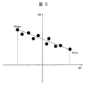
- FIG. 5 is a diagram illustrating another example of the correction function in the first embodiment, and is a diagram illustrating a correction function of the voltage target value according to the difference in active power.
- the change dV of the voltage target value according to the difference dP of the active power between the optimum power flow calculation and the device control related to the monitoring point 210 of the local system 112 in a plurality of time sections is linearized by the least square method or the like. Identifies the function.
- FIG. 6 is a diagram illustrating another example of the correction function in the first embodiment, and is a diagram illustrating a correction function of the voltage target value according to the power loss difference.
- dV is identified as a linear function by the least square method or the like.
- FIG. 7 is a diagram illustrating another example of the correction function in the first embodiment, and is a diagram illustrating a correction function of the voltage target value according to the difference in the transformer tap position.
- the change in voltage target value dV according to the difference dTapPosition of the transformer tap position between the optimum power flow calculation and the device control related to the monitoring point 210 of the local system 112 in a plurality of time sections is represented by the least square method or the like. To identify a linear function.
- FIG. 8 is a diagram illustrating another example of the correction function in the first embodiment, and is a diagram illustrating a correction function of the voltage target value according to the difference in the number of phase-adjusting devices in the substation.
- the change amount dV of the value is identified as a linear function by the least square method or the like.
- FIG. 9 is a diagram illustrating an example of a correction function in the first embodiment, and is a diagram illustrating a correction function of a voltage target value according to a reactive power difference generated by a reactive power adjusting device included in the generator.
- the change amount dV of the target value is identified as a linear function by the least square method or the like.
- FIG. 10 is a diagram illustrating an example of a correction function in the first embodiment, and is a diagram illustrating a correction function of a voltage target value according to a voltage difference of an automatic voltage regulator provided in the generator.
- the variation dV is identified as a linear function by the least square method or the like.
- FIG. 11 is a diagram illustrating an example of a correction function according to the first embodiment, in which a voltage target value corresponding to a difference in voltage between the optimum power flow calculation and the device control related to a monitoring point and other monitoring points is shown. It is a figure which shows a correction function.
- the change amount dV of the voltage target value corresponding to the voltage difference dVa ⁇ Vb between the optimum power flow calculation and the device control related to the monitoring point 210 and other monitoring points of the local system 112 in a plurality of time sections is shown. It is identified as a linear function by the method of least squares.
- the correction function D1 can be said to define the sensitivity of the monitoring point voltage with respect to the control amount.
- the central control unit 101 outputs at least one of the control target value 121 stored in the result database DB1 and the correction function D1 by the output device.
- the central control unit 101 and the device control device 110 existing in the local system 112 and Accordingly, one or more correction functions D1 shown in FIGS. 4 to 11 are created and given according to the type of control amount.
- the local control device 109 inputs the control target value 121 and one or more correction functions D1 to the local system 112.
- the correction function D1 includes one or more of FIG. 4 to FIG. 11, and the local control device 109 obtains data D3 at time t1 that is acquired for calculating the optimum power flow for the voltage data of the vertical axis item of the correction function D1. And the difference dV from the data D4 at time t2 acquired for device control, and if the voltage data does not vary within this time difference, the control target value 121 is not corrected by the correction function D1. .
- the control target value 121 is corrected by the correction function D1. For example, when a voltage difference dV occurs between times t1 and t2 in FIG. 4, the control amount by the device control device 110 necessary to eliminate the voltage difference dV is determined and set as the control amount target value 122, A control amount target value 122 is given to the device controller 110 of the voltage / reactive power control device to control the voltage / reactive power control device.
- the relationship between the control target value 121, the control amount target value 122, and the correction function D1 will be described using the example of the tapped transformer of FIG.
- the monitoring point voltage at the time when the entire system calculation is performed is 100 (V)
- the monitoring point voltage at the time when the device is individually controlled is 95 (V).
- the control target value 121 indicates a monitoring point voltage of 100 (V), but to achieve this, it is necessary to increase it by 5 (V).
- the transformer tap position is determined from the characteristics shown in FIG. It is necessary to give a command for increasing the first stage as the control amount target value 122.
- the equipment control amount provided by the device control apparatus 110 is a control amount for raising the transformer tap position by one stage.
- Example 1 which showed the example of a structure in FIG. 1 comprised the voltage and reactive power control apparatus by the central control system in the voltage and reactive power control system.
- a control target value and a correction function D1 for each local system as a result of power flow calculation with the voltage / reactive power control device arranged at the center are output.
- the local control device of each local system appropriately modifies the control target value 121 using the local system data D4 from the local system database DB4 to obtain the control amount target value 122, and the voltage / It is a system configuration of role sharing that controls reactive power control equipment.
- a voltage / reactive power control device by an individual control method is configured.
- the voltage / reactive power control device is arranged for each local system, and the control target value and the correction function D1 for the local system obtained from the host are obtained by using the local system data D4 from the local system database DB4.
- This is a system configuration of role sharing that appropriately corrects and controls the voltage / reactive power control device in the local system.
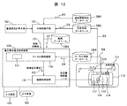
- FIG. 12 is a block diagram illustrating a configuration of the voltage / reactive power control apparatus according to the second embodiment of the present invention.
- the voltage / reactive power control device 130 according to the second embodiment includes a local control device 109 including a control target value correcting unit 131 and a device control device 110.
- the past history power database DB2, the entire system database DB3, and the local system database DB4 are connected to the voltage / reactive power control device 130 as appropriate directly or indirectly via a communication network capable of transmitting and receiving data.
- the other configuration in FIG. 12 is the same as that described with reference to FIG.
- the control target value correcting means 131 in the local control device 139 receives the local system data D4 from the local system database DB4, the control target value 121 transmitted from the central control device 101, and the correction function D1 as inputs, and the central control device 101 outputs them.
- the value of the tidal current difference is corrected. It is input to D1 and output as a corrected control amount target value 122. If it is determined that no tidal current difference occurs, it is output as it is.
- FIG. 13 is a diagram illustrating an overall processing flow of the voltage / reactive power control apparatus 130 according to the second embodiment.
- the control target value correcting means 131 of the voltage / reactive power control device 130 acquires the control target value from the central control device 101 (processing step S141), and also acquires the correction function (processing step S142). Subsequently, the local system information D4 is acquired from the local system database DB4 or the entire system information D3 is acquired from the entire system database DB3 (processing step S143), and the state difference of the system between the optimum power flow calculation time and the device control time is calculated ( Processing step S144).
- control amount target value 122 is obtained based on the correction function (processing step S146). Finally, the control target value is transmitted to the device control apparatus 110 (processing step S147).
- the voltage / reactive power control device 130 may input at least one of the control target value stored in the result database DB1 and the correction function.
- Example 3 also constitutes a voltage / reactive power control device using a central control system.
- the difference from the central control system of the first embodiment is that the voltage / reactive power control device includes a local control device. Therefore, the device control apparatus is provided with a signal that takes into account the correction of the control amount fluctuation due to the time difference between the time of calculating the optimum power flow and the time of device control.
- the central control apparatus 101 receives the entire system data D3 from the entire system database DB3, calculates the control target value 121 to be passed to the local control apparatus 109 by the optimum power flow calculation means 102, and transmits it to the local control means 109. .
- the central control means 101 receives the past history tidal current data D2 from the past history tidal current database DB2, calculates the correction function D1 associated with the tidal current state change at the control target value 121, and stores the correction function D1 in the result database DB1. And transmits it to the local control means 109.
- the local control device 109 receives the local system data D4 transmitted from the local system database DB4, the control target value 121 transmitted from the central control means 101, and the correction function D1, and the control target output by the voltage / reactive power control device 100.
- the value of the tidal current difference is calculated as the correction function D1.
- a control target value determining and correcting means for outputting the control target value as it is when it is determined that no tidal current difference is generated.
- SYMBOLS 100 Voltage / reactive power control apparatus, 101: Central control means, 102: Optimal power flow calculation means, DB1: Result database, 104: Input device, 105: Output device, DB2: Past history power flow database, DB3: Whole system database, DB4: Local system database, 109: Local control device, 110: Equipment control device, 111: Overall system, 112: Local system, 210: Monitoring point, 114: Shunt reactor, 115: Power capacitor, 116: Tap switching at load With transformer, 117: Generator with automatic voltage regulator
Landscapes
- Engineering & Computer Science (AREA)
- Power Engineering (AREA)
- Medical Informatics (AREA)
- Artificial Intelligence (AREA)
- Computer Vision & Pattern Recognition (AREA)
- Evolutionary Computation (AREA)
- Health & Medical Sciences (AREA)
- Software Systems (AREA)
- Physics & Mathematics (AREA)
- General Physics & Mathematics (AREA)
- Automation & Control Theory (AREA)
- Supply And Distribution Of Alternating Current (AREA)
- Remote Monitoring And Control Of Power-Distribution Networks (AREA)
Abstract
制御遅れが生じる状況や電圧基準値設定時の系統条件が常に再現されるとは限らないという状況においても、適正に制御できるような電圧・無効電力制御装置、方法、および電圧・無効電力制御システムを提供する。電力系統を適宜に分割したローカル系統に監視点を設定し、ローカル系統は前記監視点の電圧・無効電力を調整可能な電圧・無効電力制御機器を備えている電力系統に適用される電圧・無効電力制御システムであって、電力系統の全体系統データを用いた最適潮流計算に基づいて、ローカル系統の監視点の電圧・無効電力の制御目標値を設定するとともに、電力系統の状態の過去履歴情報を用いて、制御目標値を監視点に関わる電力系統の状態変化に伴い補正する補正関数を生成し、制御目標値と、少なくとも1つ以上の補正関数を出力する中央制御手段と、中央制御手段から得た制御目標値が、ローカル系統の系統データと相違するときに補正関数を用いて制御目標値を達成するに必要な電圧・無効電力制御機器の制御量を算出するローカル制御装置と、ローカル制御装置からの制御量に応じて電圧・無効電力制御機器を制御する機器制御装置を含む。
Description
本発明は、電力系統の監視点の電圧を許容範囲内に収め、無効電力のバランスを取るための電圧・無効電力制御装置、方法、および電圧・無効電力制御システムに関する。
電力系統は、エネルギーの需要増大や電力自由化に伴い、規模の拡大、電力事業者と電源の多様化・分散化が進んでいる。そのため、電力系統の電力潮流は不確実性を増し、電力品質の低下を招く要因になることが懸念されている。このことから高品質かつ安定な電圧管理と効果的な電力供給が求められている。
電力系統では負荷の状態変化により無効電力が変化すると共に電圧も変化するため、従来から電圧規定値や発電機無効電力の制約を満足しながら電力損失の最小化を図るよう電圧・無効電力制御が行われている。電力を安定供給するためには、電力系統の所定の位置に監視点を設け、時々刻々と変化する監視点の電圧および無効電力を目標値に近づける、もしくは、規定範囲に納めるように制御することが必要である。
電圧・無効電力の制御方式には、大きく分けて中央制御方式、個別制御方式、階層制御方式がある。
中央制御方式は、対象となる電力系統全体の監視点の電圧・無効電力の情報を1箇所に集め、電力系統全体として電圧および無効電力を規定範囲に収め、かつ送電損失が最小になるようにするなどの最適化計算を行い、その結果を監視点付近の電圧・無効電力制御機器に動作指令するものである。中央制御方式による電圧・無効電力制御装置としては、特許文献1などに例示されているように、制御時間遅れによる制御の遅れを、過去の履歴データを用いたフィードフォワード制御により電圧変動を予測し、その電圧変化に制御が追従できるようにする装置が提案されている。
個別制御方式は、電力系統の全領域を小領域に分割し(系統領域と呼ぶ)、それぞれの系統領域において、予め与えられた基準電圧値を維持するよう電圧・無効電力を制御するものである。個別制御方式による電圧・無効電力制御装置としては、特許文献2などに例示されているように、所定の変電所よりも下流側の回路を模擬した回路モデルに、所定変電所よりも上流側の電圧と所定変電所が供給する有効電力および無効電力を入力し、所定変電所が供給する無効電力が規定の条件を満たすこととなる変圧器タップと調相設備の制御量を算出する装置が提案されている。
階層制御方式は、電力系統を電圧階級に沿って階層的に分割し(系統階層と呼ぶ)、系統階層の最上位において演算装置が、またそれぞれの系統階層において、基準電圧値を維持するよう電圧・無効電力を制御するものである。階層制御方式による電圧・無効電力制御装置としては、特許文献3などに例示されているように、電圧階級に沿って階層的に複数に分割された電力系統ブロックがそれぞれ自立分散的に無効電力のバランスを取りながら強調的に電圧制御を行う個別制御部とブロック毎の所定の条件を満たす制御目標電圧の最適値の算定を行う中央計算部とを含む装置が提案されている。
中央制御方式および階層制御方式によれば、電力系統全体の情報を中央もしくは上位の系統階層に集めて一括処理するので、データの伝送量や処理量が多くなることから、特に電力系統の負荷が急変した時に制御遅れが生じるという問題点を有する。
これに対して、特許文献1では、電圧変動を予測し、その電圧変化に制御が追従できるように制御機器に関する電圧基準値の補正を行っているが、予測に基づく補正は、必ずしも予測どおりにならないという問題がある。また特許文献3では、自立分散的に無効電力のバランスを取りながら協調的に電圧制御を行う個別制御部を設けているが、自立分散的では個々の監視点における電圧が規定範囲に収まったとしても、必ずしも全体最適な無効電力のバランスを取りえないという問題がある。
個別制御方式は、予めオフラインで計算された基準電圧値を基に制御を行うものであるが、基準値設定時の系統条件が常に再現されるとは限らず、送電損失が最小となるような制御を行うことが難しいという問題がある。
以上のことから本発明においては、前述したような問題を解消するものであって、制御遅れが生じる状況や電圧基準値設定時の系統条件が常に再現されるとは限らないという状況においても、適正に制御できるような電圧・無効電力制御装置、方法、および電圧・無効電力制御システムを提供することを目的としている。
以上のことから本発明は、「電力系統を適宜に分割したローカル系統に監視点を設定し、ローカル系統は前記監視点の電圧・無効電力を調整可能な電圧・無効電力制御機器を備えている電力系統に適用される電圧・無効電力制御システムであって、電力系統の全体系統データを用いた最適潮流計算に基づいて、ローカル系統の監視点の電圧・無効電力の制御目標値を設定するとともに、電力系統の状態の過去履歴情報を用いて、制御目標値を監視点に関わる電力系統の状態変化に伴い補正する補正関数を生成し、制御目標値と、少なくとも1つ以上の補正関数を出力する中央制御手段と、中央制御手段から得た制御目標値が、ローカル系統の系統データと相違するときに補正関数を用いて制御目標値を達成するに必要な電圧・無効電力制御機器の制御量を算出するローカル制御装置と、ローカル制御装置からの制御量に応じて電圧・無効電力制御機器を制御する機器制御装置を含むことを特徴とする電圧・無効電力制御システム。」である。
また本発明は、「電力系統を適宜に分割したローカル系統に監視点を設定し、ローカル系統は監視点の電圧・無効電力についての制御目標値に従い調整可能な電圧・無効電力制御機器を備えている電力系統に適用される電圧・無効電力制御装置であって、電圧・無効電力制御装置は、電力系統の全体系統データを用いた最適潮流計算に基づいて、ローカル系統の監視点の電圧・無効電力の制御目標値を設定するとともに、電力系統の状態の過去履歴情報を用いて、制御目標値を監視点に関わる電力系統の状態変化に伴い補正する補正関数を生成し、制御目標値と、少なくとも1つ以上の補正関数を出力する中央制御手段により構成されており、電圧・無効電力制御装置が与える制御目標値と補正関数により電圧・無効電力制御機器を制御することを特徴とする電圧・無効電力制御装置。」である。
また本発明は、「電力系統を適宜に分割したローカル系統に監視点を設定し、ローカル系統は監視点の電圧・無効電力についての制御目標値に従い作動する機器制御装置により調整可能な電圧・無効電力制御機器を備えている電力系統に適用される電圧・無効電力制御装置であって、電圧・無効電力制御装置は、電力系統の全体系統データを用いた最適潮流計算に基づいて、ローカル系統の監視点の電圧・無効電力の制御目標値を設定するとともに、電力系統の状態の過去履歴情報を用いて、制御目標値を監視点に関わる電力系統の状態変化に伴い補正する補正関数を生成し、制御目標値と、少なくとも1つ以上の補正関数を出力する中央制御手段と、中央制御手段から得た制御目標値が、ローカル系統の系統データと相違するときに補正関数を用いて制御目標値を達成するに必要な電圧・無効電力制御機器の制御量を算出するローカル制御装置により構成されていることを特徴とする電圧・無効電力制御装置。」である。
また本発明は、「電力系統を適宜に分割したローカル系統に監視点を設定し、ローカル系統は前記監視点の電圧・無効電力についての制御目標値に従い作動する機器制御装置により調整可能な電圧・無効電力制御機器を備えている電力系統に適用される電圧・無効電力制御装置であって、電圧・無効電力制御装置は、電力系統の全体系統データを用いた最適潮流計算に基づいて、ローカル系統の監視点の電圧・無効電力の制御目標値と、電力系統の状態の過去履歴情報を用いて、制御目標値を監視点に関わる電力系統の状態変化に伴い補正する補正関数とを得て、制御目標値が、ローカル系統の系統データと相違するときに補正関数を用いて制御目標値を達成するに必要な電圧・無効電力制御機器の制御量を算出するローカル制御装置と、ローカル制御装置からの制御量に応じて電圧・無効電力制御機器を制御する機器制御装置を含むことを特徴とする電圧・無効電力制御装置。」である。
また本発明は、「電力系統を適宜に分割したローカル系統に監視点を設定し、ローカル系統は監視点の電圧・無効電力を調整可能な電圧・無効電力制御機器を備えている電力系統における電圧・無効電力制御方法であって、電力系統の全体系統データを用いた最適潮流計算に基づいて、ローカル系統の監視点の電圧・無効電力の制御目標値を設定し、電力系統の状態の過去履歴情報を用いて、制御目標値を監視点に関わる電力系統の状態変化に伴い補正する補正関数を生成し、制御目標値が、ローカル系統の系統データと相違するときに補正関数を用いて制御目標値を達成するに必要な電圧・無効電力制御機器の制御量を算出し、制御量に応じて電圧・無効電力制御機器を制御することを特徴とする電圧・無効電力制御方法。」である。
本発明によれば、制御遅れが生じる状況や電圧基準値設定時の系統条件が常に再現されるとは限らないという状況においても、適正に制御することができる。
より詳細に述べると、本発明の実施例によれば、中央制御方式や階層制御方式と比べて、制御遅れが生じた際にも例えばより送電損失が少なくなるような制御目標値を再計算する補正関数を生成することで、制御側で制御目標値を再計算して、より送電損失が少なくなるような制御ができる。また、個別制御方式に比べて、系統全体としてより送電損失を少なくする制御ができる。
以下、図面を参照しながら、本発明の実施例について説明する。
図1は、本発明の実施例1に係る電圧・無効電力制御装置を含む電圧・無効電力制御システムの全体構成を示すブロック図である。
図1において、監視、制御の対象である電力系統の全体系統111は、適宜分割された単位でのローカル系統112を複数含んで構成されており、ローカル系統112内には調相設備である分路リアクトル114、電力コンデンサ115、負荷時タップ切替器付変圧器116、自動電圧調整器付発電機117などの数存在する場合に複数備えている。なおローカル系統112は、電力系統の全体系統111を電圧階級或は領域などの観点から適宜分割した小系統ということができる。
電力系統の監視制御を行う電圧・無効電力制御装置100は、中央制御手段101、最適潮流計算手段102、結果データベースDB1、入力装置104、出力装置105を備える。過去履歴潮流データベースDB2、全体系統データベースDB3は、データの送受信が可能な通信ネットワークで電圧・無効電力制御装置100と接続されている。
電圧・無効電力制御装置100の外部には、電圧・無効電力制御装置100からの出力(制御目標値121と補正関数D1)と、ローカル系統データベースDB4からのローカル系統データD4を用いて制御目標値を算出し、機器制御装置110に与えるローカル制御装置109が備えられている。ローカル制御装置109は、ローカル系統112内の調相設備である分路リアクトル114、電力コンデンサ115、負荷時タップ切替器付変圧器116、自動電圧調整器付発電機117などの電圧・無効電力制御機器に対する制御量の目標信号(制御量目標値)122を与える。
ローカル系統112の電圧などは、監視点210に設置された計測装置(図示せず)にて計測される。監視点210は全体系統111の所定の位置に予め設定されており、監視点210で計測された電圧、電流、有効電力、無効電力といったテレメータ情報(以下TM情報と呼ぶ)、および発電機等や調相設備といった電力設備の動作状態に関するスーパービジョン情報(以下SV情報と呼ぶ)は全体系統データD3として、ある時間周期において、全体系統データベースDB3に収集される。同様にして全体系統データD3のうち、当該ローカル系統112についてのTM情報およびSV情報は、ローカル系統データD4としてローカル系統データベースDB4に収集される。
図1の構成によれば、電圧・無効電力制御装置100が与えた制御目標値121は、補正関数D1とローカル系統データD4により適宜修正されて電圧・無効電力制御機器に対する制御量が定められる。これにより、全体系統111を最適化する制御目標値121がローカル系統111の現状を反映して制御に移される。
なお力装置104は、ユーザが電圧・無効電力制御装置100に、所定の指示を行うためのインタフェースである。入力装置104は、例えば、キーボード、マウス、タッチパネル及び/又は操作ボタン等で構成される。
出力装置105は、ユーザが電圧・無効電力制御装置100からユーザに所定の情報を提供するためのインタフェースである。出力装置105は、例えば、ディスプレイ等で構成される。
また電圧・無効電力制御装置100を構成する各要素101~105に係る機能は、例えば、電圧・無効電力制御装置100の備えるCPU(Central Processing Unit)、メモリ、記憶装置(何れも図示せず)を用いて実現される。例えば、CPUが、記憶装置から所定のコンピュータプログラムをメモリに読み出して実行することにより、上述の各要素101~105に係る機能が実現される。
図2は、電力系統の全体像における全体系統111とローカル系統112との関係を示す図である。図2において、全体系統111は、大きく電源系201、送変電系202、配電系203に分けられる。電源系201の発電機204には、自動電圧調整器(Automatic Voltage Regulator:以下AVRと呼ぶ)205と自動無効電力調整器(Automatic reactive power(Q) Regulator:以下AQRと呼ぶ)206、もしくは、送電電圧制御励磁装置(Power System Voltage Regulator:以下PSVRと呼ぶ)207が備えられている。これらは、電力系統の電圧・無効電力の制御に貢献できるものであり、電圧・無効電力制御機器として、図1の機器制御装置110による制御の対象となり得るものである。
発電機204で発電された電力は、例えば発電端の11kVから変圧器208で275kVに昇圧されて送電される。さらに、別の変圧器209で275kVから500kVに昇圧されてより遠方に送電される。
ローカル系統112は、電力系統の全体系統111を電圧階級或は領域などの観点から適宜分割した小系統であるが、図2におけるローカル系統112は、例えば電圧階級500kVの監視点210に、電圧・無効電力制御機器として負荷時タップ切替器付変圧器211の3次巻線に電力コンデンサ212および分路リアクトル213を接続して構成された領域で構成されている。
実施例1においては、ローカル系統112の負荷時タップ切替器付変圧器211を制御対象として電圧・無効電力の制御を行うローカル制御装置109に対して、制御目標値121を送る中央制御方式もしくは階層制御方式の電圧・無効電力制御装置100を対象にして説明する。
図3は、実施例1における電圧・無効電力制御装置100の全体の処理フローを示す図である。図1に示す電圧・無効電力制御装置100の中央制御手段101は、全体系統データベースDB3から全体系統データD3を取得し(処理ステップS201)、最適潮流計算手段102において制御目標値121を算出する(処理ステップS202)。ここまでの処理は、全体系統111における潮流を最適化する電圧・無効電力を計算し、計算した全データの中から、このうち図2におけるローカル系統112に関与するデータのみを、ローカル系統112の制御目標値121として抽出して出力したものである。なお、複数のローカル系統のそれぞれに対して、全体の状態を最適化するときのローカルな制御目標値121が与えられている。
併せて、中央制御手段101は、電力系統の状態の過去履歴潮流データベースDB2から過去履歴潮流データD2を取得し(処理ステップS203)、複数の時間断面における状態変化に対する電圧偏差量を算出する(処理ステップS204)。続いて各時間断面の電圧偏差量から補正関数D1を算出し(処理ステップS205)、結果データベースDB1に補正関数D1を格納する(処理ステップS206)。そのうえで制御目標値121と、補正関数D1の少なくとも1つ以上をローカル制御装置109へ送信する(処理ステップS207)。
この部分の処理は、全体を最適化する観点から定めたローカル系統112の制御目標値121が、実際にローカル系統112の制御を行う状態では必ずしも最適ではないことがありうることから、ローカルに補正を行う時の指標を補正関数D1として与えたものである。補正関数D1は、補正を行うとしても、補正するときにどの程度の大きさの補正を与えればよいのかを定めるための指標である。
以下、各種の補正関数D1の例について図4から図11を用いて説明する。補正関数D1は制御目標値である電力系統監視点210の電圧と、機器制御装置110が与える制御量との関係を示す関数であり、図4から図11では、電圧偏差を縦軸に、制御量偏差を横軸に採用した示した関数として表している。なお機器制御装置110が与える制御量には複数のものがあるために、想定される制御量毎に図4から図11の補正関数D1を例示している。
図4は、実施例1における補正関数D1の一例として制御量が無効電力であるときを示す図である。図4は、無効電力差分dQ(横軸)に対する電圧変化量dV(縦軸変化分)の関係を示す補正関数D1の一例である。ここでは、複数の時間断面のローカル系統112の監視点210に関わる最適潮流計算時と機器制御時での無効電力の差分dQに応じた電圧目標値の変化量dVを最小二乗法等で線形関数に同定している。例えば、ある時間断面tにおける無効電力の差分dQに対して、電圧目標値の変化量dVが、数A、Bを用いて(1)式で成り立つような補正関数とする。
[数1]
dV(t)=A*dQ(t)+B (1)
図5は、実施例1における補正関数の他の一例を示す図であり、有効電力の差分に応じた電圧目標値の補正関数を示す図である。図5において、複数の時間断面のローカル系統112の監視点210に関わる最適潮流計算時と機器制御時での有効電力の差分dPに応じた電圧目標値の変化量dVを最小二乗法等で線形関数に同定している。
[数1]
dV(t)=A*dQ(t)+B (1)
図5は、実施例1における補正関数の他の一例を示す図であり、有効電力の差分に応じた電圧目標値の補正関数を示す図である。図5において、複数の時間断面のローカル系統112の監視点210に関わる最適潮流計算時と機器制御時での有効電力の差分dPに応じた電圧目標値の変化量dVを最小二乗法等で線形関数に同定している。
図6は、実施例1における補正関数の他の一例を示す図であり、電力損失の差分に応じた電圧目標値の補正関数を示す図である。図6において、複数の時間断面のローカル系統112の監視点210に関わる最適潮流計算時と機器制御時での無効電力損失の差分dPlossあるいは有効電力損失の差分dQlossに応じた電圧目標値の変化量dVを最小二乗法等で線形関数に同定している。
図7は、実施例1における補正関数の他の一例を示す図であり、変圧器タップ位置の差分に応じた電圧目標値の補正関数を示す図である。図7において、複数の時間断面のローカル系統112の監視点210に関わる最適潮流計算時と機器制御時での変圧器タップ位置の差分dTapPositionに応じた電圧目標値の変化量dVを最小二乗法等で線形関数に同定している。
図8は、実施例1における補正関数の他の一例を示す図であり、変電所の調相機器の投入台数の差分に応じた電圧目標値の補正関数を示す図である。図8において、複数の時間断面のローカル系統112の監視点210に関わる最適潮流計算時と機器制御時での変電所の調相機器の投入台数の差分d(SCn、ShRn)に応じた電圧目標値の変化量dVを最小二乗法等で線形関数に同定している。
図9は、実施例1における補正関数の一例を示す図であり、発電機が備える無効電力調整機器が発生する無効電力の差分に応じた電圧目標値の補正関数を示す図である。図9において、複数の時間断面のローカル系統112の監視点210に関わる最適潮流計算時と機器制御時での発電機が備える無効電力調整機器が発生する無効電力の差分dQ,AQRに応じた電圧目標値の変化量dVを最小二乗法等で線形関数に同定している。
図10は、実施例1における補正関数の一例を示す図であり、発電機が備える自動電圧調整機器の電圧の差分に応じた電圧目標値の補正関数を示す図である。図10において、複数の時間断面のローカル系統112の監視点210に関わる最適潮流計算時と機器制御時での発電機が備える自動電圧調整機器の電圧の差分dV,AVRに応じた電圧目標値の変化量dVを最小二乗法等で線形関数に同定している。
図11は、実施例1における補正関数の一例を示す図であり、監視点とそれ以外の監視点に関わる前記最適潮流計算時と前記機器制御時での電圧の差分に応じた電圧目標値の補正関数を示す図である。図11において、複数の時間断面のローカル系統112の監視点210と他の監視点に関わる最適潮流計算時と機器制御時での電圧の差分dVa-Vbに応じた電圧目標値の変化量dVを最小二乗法等で線形関数に同定している。
図4から図11の例示から明らかなように、補正関数D1は要するに制御量に対する監視点電圧の感度を定めたものということができる。中央制御手段101は、結果データベースDB1に格納された制御目標値121と、補正関数D1の少なくとも1つ以上に関して出力装置により出力するが、この場合にローカル系統112内に存在する機器制御装置110および、これによる制御量の種別に応じて、図4から図11のいずれか1つ以上の補正関数D1が作成されて与えられることになる。
ローカル制御装置109は、当該ローカル系統112に対して制御目標値121と、1つ以上の補正関数D1を入力している。補正関数D1は、図4から図11の1つ以上を含み、ローカル制御装置109では補正関数D1の縦軸軸項目の電圧のデータについて、最適潮流計算のためにデータ取得した時刻t1のデータD3と、機器制御のためにデータ取得した時刻t2のデータD4との差分dVを求め、この時間差内に電圧データに変動がないのであれば、当該補正関数D1による制御目標値121の補正は行わない。
この時間差内に電圧データに変動がある場合、当該補正関数D1による制御目標値121の補正を行う。例えば図4で時刻t1とt2の間に電圧差分dVが発生したときには、電圧差分dVを解消するに必要な機器制御装置110による制御量を決定して制御量目標値122とし、ローカル系統112内の電圧・無効電力制御機器の機器制御装置110に制御量目標値122を与えて電圧・無効電力制御機器を制御する。
ここで制御目標値121と制御量目標値122および補正関数D1の関係について、図7のタップ付変圧器の例で説明する。例えば、全体系統演算を行った時点での監視点電圧は100(V)であり、個別に機器制御をしようとしている時点での監視点電圧は95(V)であったとする。制御目標値121は監視点電圧100(V)を指示したのに対し、これを達成するには5(V)上昇させる必要があり、このためには図7の特性からは変圧器タップ位置を1段上昇させる指令を制御量目標値122として与える必要がある。なおこの場合に機器制御装置110が与える設備の制御量は、変圧器タップ位置を1段上昇させるための制御量ということになる。
尚電力系統の運用上は、電圧の時間差分について所定制限量以上の差分のみ補正制御に反映することとして頻繁な制御による動乱を抑止し、あるいは電圧・無効電力制御機器が当該ローカル系統内に場合に複数存在する場合に、そのすべてに対応するのではなく、最も効果の高い電圧・無効電力制御機器の機器制御装置110による制御を実行するといった対応策も有効である。
なお図1に構成例を示した実施例1は、電圧・無効電力制御システムにおいて中央制御方式により電圧・無効電力制御装置を構成したものということができる。中央側に電圧・無効電力制御装置を配置して潮流計算を行った結果としての各ローカル系統に対する制御目標値及び補正関数D1を出力する。個別には、各ローカル系統のローカル制御装置が、ローカル系統データベースDB4からのローカル系統データD4を用いて制御目標値121を適宜修正して制御量目標値122を得、当該ローカル系統内の電圧・無効電力制御機器を制御するという役割分担のシステム構成である。
これに対し実施例2では、個別制御方式による電圧・無効電力制御装置を構成したものである。ここでは、電圧・無効電力制御装置はローカル系統ごとに配置され、上位から得られた当該ローカル系統に対する制御目標値及び補正関数D1をローカル系統データベースDB4からのローカル系統データD4を用いて制御目標値を適宜修正し、当該ローカル系統内の電圧・無効電力制御機器を制御するという役割分担のシステム構成である。
図12は、本発明の実施例2に係る電圧・無効電力制御装置の構成を示すブロック図である。実施例2における電圧・無効電力制御装置130は、制御目標値補正手段131を備えるローカル制御装置109と機器制御装置110とを備える。なお、過去履歴潮流データベースDB2、全体系統データベースDB3、ローカル系統データベースDB4は、データの送受信が可能な通信ネットワーク経由で適宜直接あるいは間接的に電圧・無効電力制御装置130と接続されている。なお図12における他の構成は図2で説明したと同じものであるので、ここでの説明を省略する。
ローカル制御装置139における制御目標値補正手段131は、ローカル系統データベースDB4からローカル系統データD4、中央制御装置101から送信される制御目標値121、補正関数D1を入力として、中央制御装置101が出力する制御目標値121の出力時刻におけるローカル系統情報D4と制御目標値121および補正関数D1の入力時刻におけるローカル系統情報D4との間に潮流差が生じると判定した場合に、潮流差の値を補正関数D1に入力して、補正した制御量目標値122として出力し、潮流差が生じないと判定した場合にはそのまま出力する。
図13は、実施例2における電圧・無効電力制御装置130の全体の処理フローを示す図である。電圧・無効電力制御装置130の制御目標値補正手段131は、中央制御装置101から制御目標値を取得し(処理ステップS141)、併せて補正関数を取得する(処理ステップS142)。引き続き、ローカル系統データベースDB4からローカル系統情報D4を、もしくは全体系統データベースDB3から全体系統情報D3を取得し(処理ステップS143)、最適潮流計算時と機器制御時とにおける系統の状態差を算出する(処理ステップS144)。系統情報の状態に差があると判定し(処理ステップS145)、系統情報の状態に差がある場合は、補正関数に基づいて制御量目標値122を得る(処理ステップS146)。最後に制御目標値を機器制御装置110に送信する(処理ステップS147)。
実施例2における電圧・無効電力制御装置130は、結果データベースDB1に格納された制御目標値と、補正関数の少なくとも1つ以上に関して入力するのが良い。
実施例3もまた中央制御方式による電圧・無効電力制御装置を構成したものである。実施例1の中央制御方式と異なるのは、ここでは、電圧・無効電力制御装置はローカル制御装置を含んで構成された点である。したがって、機器制御装置には最適潮流計算時と機器制御時との間に時間差による制御量変動分の補正が考慮された信号が与えられている。
図14に示す実施例3の電圧・無効電力制御装置100は、ローカル制御装置109を含んでいる。この構成では、中央制御装置101は、全体系統データベースDB3から全体系統データD3を入力とし、最適潮流計算手段102によりローカル制御装置109に渡す制御目標値121を算出し、ローカル制御手段109へ送信する。併せて中央制御手段101は、過去履歴潮流データベースDB2から過去履歴潮流データD2を入力とし、制御目標値121における潮流状態変化に伴う補正関数D1を算出し、結果データベースDB1に前記補正関数D1を記憶すると共にローカル制御手段109へ送信する。
ローカル制御装置109はローカル系統データベースDB4から送信されるローカル系統データD4、中央制御手段101から送信される制御目標値121、補正関数D1を入力として、電圧・無効電力制御装置100が出力する制御目標値121の出力時刻におけるローカル系統情報D4と制御目標値121および補正関数D1の入力時刻におけるローカル系統情報D4との間に潮流差が生じると判定した場合に、潮流差の値を前記補正関数D1に入力して、補正した制御目標値として出力し、潮流差が生じないと判定した場合に、制御目標値をそのまま出力する制御目標値判定補正手段を備える。
100:電圧・無効電力制御装置,101:中央制御手段、102:最適潮流計算手段,DB1:結果データベース,104:入力装置,105:出力装置,DB2:過去履歴潮流データベース,DB3:全体系統データベース,DB4:ローカル系統データベース,109:ローカル制御装置,110:機器制御装置,111:全体系統,112:ローカル系統,210:監視点,114:分路リアクトル,115:電力コンデンサ,116:負荷時タップ切替器付変圧器,117:自動電圧調整器付発電機
Claims (9)
- 電力系統を適宜に分割したローカル系統に監視点を設定し、前記ローカル系統は前記監視点の電圧・無効電力についての制御目標値に従い調整可能な電圧・無効電力制御機器を備えている電力系統に適用される電圧・無効電力制御装置であって、
電圧・無効電力制御装置は、前記電力系統の全体系統データを用いた最適潮流計算に基づいて、前記ローカル系統の前記監視点の電圧・無効電力の制御目標値を設定するとともに、前記電力系統の状態の過去履歴情報を用いて、前記制御目標値を前記監視点に関わる電力系統の状態変化に伴い補正する補正関数を生成し、前記制御目標値と、少なくとも1つ以上の前記補正関数を出力する中央制御手段により構成されており、
電圧・無効電力制御装置が与える前記制御目標値と前記補正関数により前記電圧・無効電力制御機器を制御することを特徴とする電圧・無効電力制御装置。 - 請求項1に記載の電圧・無効電力制御装置であって、
前記中央制御手段から得た前記制御目標値が、前記ローカル系統の系統データと相違するときに前記補正関数を用いて前記制御目標値を達成するに必要な前記電圧・無効電力制御機器の制御量を算出するローカル制御装置を備え、
前記監視点の電圧・無効電力についての制御目標値に従い作動する機器制御装置を介して前記電圧・無効電力制御機器を制御する
ことを特徴とする電圧・無効電力制御装置。 - 請求項1に記載の電圧・無効電力制御装置であって、
前記中央制御手段の機能は、ローカル制御装置に組み込まれており、
前記ローカル制御装置は、前記電力系統の全体系統データを用いた最適潮流計算に基づいて、前記ローカル系統の前記監視点の電圧・無効電力の制御目標値と、前記電力系統の状態の過去履歴情報を用いて、前記制御目標値を前記監視点に関わる電力系統の状態変化に伴い補正する補正関数とを得て、前記制御目標値が、前記ローカル系統の系統データと相違するときに前記補正関数を用いて前記制御目標値を達成するに必要な前記電圧・無効電力制御機器の制御量を算出し、
該ローカル制御装置からの制御量に応じて作動する機器制御装置を介して前記電圧・無効電力制御機器を制御する
ことを特徴とする電圧・無効電力制御装置。 - 前記ローカル系統は、前記監視点の電圧・無効電力についての制御目標値に従い調整可能な機器制御装置を介して操作される複数の電圧・無効電力制御機器を備え、
前記電圧・無効電力制御機器が請求項1に記載の電圧・無効電力制御装置により操作される電圧・無効電力制御システム。 - 請求項4に記載の電圧・無効電力制御システムであって、
前記ローカル系統は、前記監視点の電圧・無効電力を調整可能な複数種類の電圧・無効電力制御機器を備えており、前記補正関数は、前記電圧・無効電力制御機器の種類に応じた複数種類の補正関数であることを特徴とする電圧・無効電力制御システム。 - 請求項4に記載の電圧・無効電力制御システムであって、
前記電圧・無効電力制御装置は、前記監視点の電圧・無効電力についての前記制御目標値が、前記全体系統データを用いた最適潮流計算と、前記ローカル制御装置による制御実行時で相違する値であるときに、前記補正関数を用いて前記制御目標値を達成するに必要な前記電圧・無効電力制御機器の制御量を算出することを特徴とする電圧・無効電力制御システム。 - 請求項4に記載の電圧・無効電力制御システムであって、
前記補正関数は、前記制御目標値と前記電圧・無効電力制御機器の制御量の関係を定めたものであることを特徴とする電圧・無効電力制御システム。 - 請求項4に記載の電圧・無効電力制御システムであって、
前記補正関数は、前記制御目標値と前記電圧・無効電力制御機器の制御量の関係を定めたものであるとともに、前記制御量は前記電圧・無効電力制御機器における無効電力、有効電力、電力損失、変圧器タップ位置、調相機器の投入台数についてのものであり、その1つ以上が前記中央制御手段により得られることを特徴とする電圧・無効電力制御システム。 - 電力系統を適宜に分割したローカル系統に監視点を設定し、前記ローカル系統は前記監視点の電圧・無効電力を調整可能な電圧・無効電力制御機器を備えている電力系統における電圧・無効電力制御方法であって、
前記電力系統の全体系統データを用いた最適潮流計算に基づいて、前記ローカル系統の前記監視点の電圧・無効電力の制御目標値を設定し、前記電力系統の状態の過去履歴情報を用いて、前記制御目標値を前記監視点に関わる電力系統の状態変化に伴い補正する補正関数を生成し、前記制御目標値が、前記ローカル系統の系統データと相違するときに前記補正関数を用いて前記制御目標値を達成するに必要な前記電圧・無効電力制御機器の制御量を算出し、該制御量に応じて前記電圧・無効電力制御機器を制御することを特徴とする電圧・無効電力制御方法。
Priority Applications (3)
| Application Number | Priority Date | Filing Date | Title |
|---|---|---|---|
| PL16866101T PL3379676T3 (pl) | 2015-11-20 | 2016-10-25 | Urządzenie sterujące napięciem/mocą bierną, sposób oraz system sterujący napięciem/mocą bierną |
| EP16866101.5A EP3379676B1 (en) | 2015-11-20 | 2016-10-25 | Voltage/reactive power control device and method, and voltage/reactive power control system |
| US15/777,433 US10790667B2 (en) | 2015-11-20 | 2016-10-25 | Voltage/reactive power control apparatus, method, and voltage/reactive power control system |
Applications Claiming Priority (2)
| Application Number | Priority Date | Filing Date | Title |
|---|---|---|---|
| JP2015-227425 | 2015-11-20 | ||
| JP2015227425A JP6587522B2 (ja) | 2015-11-20 | 2015-11-20 | 電圧・無効電力制御装置、方法、および電圧・無効電力制御システム |
Publications (1)
| Publication Number | Publication Date |
|---|---|
| WO2017086099A1 true WO2017086099A1 (ja) | 2017-05-26 |
Family
ID=58718811
Family Applications (1)
| Application Number | Title | Priority Date | Filing Date |
|---|---|---|---|
| PCT/JP2016/081530 Ceased WO2017086099A1 (ja) | 2015-11-20 | 2016-10-25 | 電圧・無効電力制御装置、方法、および電圧・無効電力制御システム |
Country Status (5)
| Country | Link |
|---|---|
| US (1) | US10790667B2 (ja) |
| EP (1) | EP3379676B1 (ja) |
| JP (1) | JP6587522B2 (ja) |
| PL (1) | PL3379676T3 (ja) |
| WO (1) | WO2017086099A1 (ja) |
Cited By (2)
| Publication number | Priority date | Publication date | Assignee | Title |
|---|---|---|---|---|
| CN110198053A (zh) * | 2019-04-19 | 2019-09-03 | 山东大学 | 一种集中与就地相结合的微电网实时电压控制方法及系统 |
| WO2022230128A1 (ja) | 2021-04-28 | 2022-11-03 | 三菱電機株式会社 | 電力制御システム、給電指令システム、および電力制御方法 |
Families Citing this family (9)
| Publication number | Priority date | Publication date | Assignee | Title |
|---|---|---|---|---|
| JP6876406B2 (ja) * | 2016-10-20 | 2021-05-26 | 株式会社日立製作所 | 電圧無効電力運用支援装置および支援方法、並びに電圧無効電力運用監視制御装置および監視制御方法 |
| JP6996549B2 (ja) * | 2017-03-08 | 2022-01-17 | 日本電気株式会社 | 通信ネットワークのための装置及び方法 |
| CN109066687A (zh) * | 2018-08-22 | 2018-12-21 | 深圳先进技术研究院 | 一种电力系统潮流计算方法、系统及电子设备 |
| CN109193689B (zh) * | 2018-09-21 | 2021-09-03 | 国电南瑞科技股份有限公司 | 电压无功调控时段划分方法及装置 |
| JP7086820B2 (ja) * | 2018-11-07 | 2022-06-20 | 三菱重工業株式会社 | 無効電力制御装置及び無効電力制御方法 |
| JP7160747B2 (ja) * | 2019-04-16 | 2022-10-25 | 株式会社日立製作所 | 発電機の制御状態決定装置及び方法 |
| US11349310B2 (en) * | 2019-11-15 | 2022-05-31 | Smart Wires Inc. | Adaptive control technique for stability of impedance injection unit |
| JP6950805B1 (ja) | 2020-11-11 | 2021-10-13 | 富士電機株式会社 | 電力配分装置、電力配分方法、およびプログラム |
| CN118983951B (zh) * | 2024-10-18 | 2025-02-11 | 福建优迪电力技术有限公司 | 一种基于智慧变电站多参量的综合辅控系统 |
Citations (5)
| Publication number | Priority date | Publication date | Assignee | Title |
|---|---|---|---|---|
| JPH09322404A (ja) * | 1996-05-31 | 1997-12-12 | Kansai Electric Power Co Inc:The | 配電系統制御装置 |
| JP2012005277A (ja) * | 2010-06-18 | 2012-01-05 | Hitachi Ltd | 潮流計算機能を備えた無効電力補償装置、およびそのシステムと方法 |
| JP2012235681A (ja) * | 2011-04-27 | 2012-11-29 | General Electric Co <Ge> | 配電ネットワークにおけるボルト/var制御調整のためのシステム、方法、および設備 |
| JP2014138471A (ja) * | 2013-01-16 | 2014-07-28 | Chugoku Electric Power Co Inc:The | 電圧調整システム |
| JP2015090580A (ja) * | 2013-11-06 | 2015-05-11 | 三菱電機株式会社 | 電圧無効電力制御装置 |
Family Cites Families (13)
| Publication number | Priority date | Publication date | Assignee | Title |
|---|---|---|---|---|
| JPH04190630A (ja) * | 1990-11-22 | 1992-07-09 | Fuji Electric Co Ltd | 電圧無効電力制御方法及び電圧無効電力制御装置 |
| JP3791188B2 (ja) | 1998-06-22 | 2006-06-28 | 株式会社日立製作所 | 電圧無効電力制御装置 |
| JP2002165367A (ja) | 2000-11-24 | 2002-06-07 | Kansai Electric Power Co Inc:The | 電圧・無効電力制御システムおよび電圧・無効電力制御方法 |
| US20120197450A1 (en) | 2011-01-27 | 2012-08-02 | General Electric Company | Systems, Methods, and Apparatus for Coordinated Volt/VAR Control in Power Distribution Networks |
| JP2012175778A (ja) | 2011-02-21 | 2012-09-10 | Tokyo Electric Power Co Inc:The | 電圧無効電力制御装置 |
| US8838284B2 (en) * | 2011-07-26 | 2014-09-16 | General Electric Company | Devices and methods for decentralized Volt/VAR control |
| JP5893544B2 (ja) * | 2011-10-31 | 2016-03-23 | パナソニック株式会社 | 電圧制御装置、電圧制御方法、電力調整装置、及び電圧制御プログラム |
| KR101374623B1 (ko) * | 2012-09-20 | 2014-03-17 | 한국전력공사 | Ems 및 dms의 협조제어 장치 및 방법 |
| JP5984601B2 (ja) * | 2012-09-21 | 2016-09-06 | 株式会社日立製作所 | 系統制御装置および系統制御方法 |
| JP5393934B1 (ja) * | 2012-11-26 | 2014-01-22 | 三菱電機株式会社 | 電圧監視制御装置、電圧制御装置および電圧監視制御方法 |
| US20140148966A1 (en) * | 2012-11-29 | 2014-05-29 | Magdy Salama | Decentralized Volt/VAR Control for Advanced Distribution Automation Systems |
| WO2015022746A1 (ja) * | 2013-08-15 | 2015-02-19 | 三菱電機株式会社 | 電圧監視制御装置および電圧制御装置 |
| US10585445B2 (en) * | 2015-02-02 | 2020-03-10 | Opus One Solutions Energy Corporation | Systems and methods for volt/VAR control in electric power management and automation systems |
-
2015
- 2015-11-20 JP JP2015227425A patent/JP6587522B2/ja active Active
-
2016
- 2016-10-25 PL PL16866101T patent/PL3379676T3/pl unknown
- 2016-10-25 WO PCT/JP2016/081530 patent/WO2017086099A1/ja not_active Ceased
- 2016-10-25 EP EP16866101.5A patent/EP3379676B1/en active Active
- 2016-10-25 US US15/777,433 patent/US10790667B2/en active Active
Patent Citations (5)
| Publication number | Priority date | Publication date | Assignee | Title |
|---|---|---|---|---|
| JPH09322404A (ja) * | 1996-05-31 | 1997-12-12 | Kansai Electric Power Co Inc:The | 配電系統制御装置 |
| JP2012005277A (ja) * | 2010-06-18 | 2012-01-05 | Hitachi Ltd | 潮流計算機能を備えた無効電力補償装置、およびそのシステムと方法 |
| JP2012235681A (ja) * | 2011-04-27 | 2012-11-29 | General Electric Co <Ge> | 配電ネットワークにおけるボルト/var制御調整のためのシステム、方法、および設備 |
| JP2014138471A (ja) * | 2013-01-16 | 2014-07-28 | Chugoku Electric Power Co Inc:The | 電圧調整システム |
| JP2015090580A (ja) * | 2013-11-06 | 2015-05-11 | 三菱電機株式会社 | 電圧無効電力制御装置 |
Non-Patent Citations (1)
| Title |
|---|
| See also references of EP3379676A4 * |
Cited By (3)
| Publication number | Priority date | Publication date | Assignee | Title |
|---|---|---|---|---|
| CN110198053A (zh) * | 2019-04-19 | 2019-09-03 | 山东大学 | 一种集中与就地相结合的微电网实时电压控制方法及系统 |
| WO2022230128A1 (ja) | 2021-04-28 | 2022-11-03 | 三菱電機株式会社 | 電力制御システム、給電指令システム、および電力制御方法 |
| US12328004B2 (en) | 2021-04-28 | 2025-06-10 | Mitsubishi Electric Corporation | Power control system, power supply instruction system, and power control method |
Also Published As
| Publication number | Publication date |
|---|---|
| US20180351361A1 (en) | 2018-12-06 |
| EP3379676B1 (en) | 2021-08-25 |
| EP3379676A1 (en) | 2018-09-26 |
| EP3379676A4 (en) | 2019-07-31 |
| JP6587522B2 (ja) | 2019-10-09 |
| JP2017099091A (ja) | 2017-06-01 |
| PL3379676T3 (pl) | 2021-12-06 |
| US10790667B2 (en) | 2020-09-29 |
Similar Documents
| Publication | Publication Date | Title |
|---|---|---|
| JP6587522B2 (ja) | 電圧・無効電力制御装置、方法、および電圧・無効電力制御システム | |
| CA3100374C (en) | Using distributed power electronics-based devices to improve the voltage and frequency stability of distribution systems | |
| CN104471852B (zh) | 多端hvdc控制的方法、主控制器和计算机可读介质 | |
| US9507367B2 (en) | Method and system for dynamic stochastic optimal electric power flow control | |
| Abdelaziz et al. | Maximum loadability consideration in droop-controlled islanded microgrids optimal power flow | |
| Usman et al. | Simulation study of load frequency control of single and two area systems | |
| JP6618659B1 (ja) | 電力変換システム及びその管理装置、並びに、分散電源装置 | |
| JP2008054385A (ja) | 系統安定化装置 | |
| US20170104366A1 (en) | Method and control device for controlling an electrical grid | |
| JP6609520B2 (ja) | マイクログリッド制御装置及び方法 | |
| Negenborn et al. | Supervisory hybrid model predictive control for voltage stability of power networks | |
| Veronica et al. | Design of load frequency control for a microgrid using D-partition method | |
| Horri et al. | Reinforcement‐learning‐based load shedding and intentional voltage manipulation approach in a microgrid considering load dynamics | |
| Roy et al. | Enhancing grid frequency regulation in low inertia modern multi‐area power systems using cascaded non‐integer control approaches with BESS‐based virtual inertia | |
| Dinesh et al. | Robust guaranteed cost output feedback control for real-time congestion management | |
| Otomega et al. | Emergency alleviation of thermal overloads using model predictive control | |
| Kim | A voltage deviation-memorizing reactive power controller for renewable energy sources | |
| CN119134411B (zh) | 孤岛交流微电网抗执行器故障和饱和的控制方法 | |
| CN117175698A (zh) | 风机群的无功控制方法及装置 | |
| JPWO2014167830A1 (ja) | 電力制御システム | |
| CN119726721A (zh) | 一种并离网无缝切换方法、装置、设备及存储介质 | |
| Oluseyi et al. | Optimal load frequency control of two area power system | |
| JP2024019980A (ja) | 系統管理装置、系統管理方法及びプログラム | |
| Hatmi et al. | Dynamic Performance of Load Frequency Control of Three Area System Using FOPID Controller with Transit Search Optimization. | |
| JP7160747B2 (ja) | 発電機の制御状態決定装置及び方法 |
Legal Events
| Date | Code | Title | Description |
|---|---|---|---|
| 121 | Ep: the epo has been informed by wipo that ep was designated in this application |
Ref document number: 16866101 Country of ref document: EP Kind code of ref document: A1 |
|
| NENP | Non-entry into the national phase |
Ref country code: DE |