WO2017090466A1 - 燃料噴射ポンプ - Google Patents
燃料噴射ポンプ Download PDFInfo
- Publication number
- WO2017090466A1 WO2017090466A1 PCT/JP2016/083546 JP2016083546W WO2017090466A1 WO 2017090466 A1 WO2017090466 A1 WO 2017090466A1 JP 2016083546 W JP2016083546 W JP 2016083546W WO 2017090466 A1 WO2017090466 A1 WO 2017090466A1
- Authority
- WO
- WIPO (PCT)
- Prior art keywords
- transmission shaft
- lubricating oil
- groove
- opening
- oil passage
- Prior art date
- Legal status (The legal status is an assumption and is not a legal conclusion. Google has not performed a legal analysis and makes no representation as to the accuracy of the status listed.)
- Ceased
Links
Images



Classifications
-
- F—MECHANICAL ENGINEERING; LIGHTING; HEATING; WEAPONS; BLASTING
- F02—COMBUSTION ENGINES; HOT-GAS OR COMBUSTION-PRODUCT ENGINE PLANTS
- F02M—SUPPLYING COMBUSTION ENGINES IN GENERAL WITH COMBUSTIBLE MIXTURES OR CONSTITUENTS THEREOF
- F02M59/00—Pumps specially adapted for fuel-injection and not provided for in groups F02M39/00 -F02M57/00, e.g. rotary cylinder-block type of pumps
- F02M59/20—Varying fuel delivery in quantity or timing
- F02M59/24—Varying fuel delivery in quantity or timing with constant-length-stroke pistons having variable effective portion of stroke
- F02M59/26—Varying fuel delivery in quantity or timing with constant-length-stroke pistons having variable effective portion of stroke caused by movements of pistons relative to their cylinders
- F02M59/28—Mechanisms therefor
-
- F—MECHANICAL ENGINEERING; LIGHTING; HEATING; WEAPONS; BLASTING
- F02—COMBUSTION ENGINES; HOT-GAS OR COMBUSTION-PRODUCT ENGINE PLANTS
- F02M—SUPPLYING COMBUSTION ENGINES IN GENERAL WITH COMBUSTIBLE MIXTURES OR CONSTITUENTS THEREOF
- F02M63/00—Other fuel-injection apparatus having pertinent characteristics not provided for in groups F02M39/00 - F02M57/00 or F02M67/00; Details, component parts, or accessories of fuel-injection apparatus, not provided for in, or of interest apart from, the apparatus of groups F02M39/00 - F02M61/00 or F02M67/00; Combination of fuel pump with other devices, e.g. lubricating oil pump
- F02M63/0001—Fuel-injection apparatus with specially arranged lubricating system, e.g. by fuel oil
-
- A—HUMAN NECESSITIES
- A61—MEDICAL OR VETERINARY SCIENCE; HYGIENE
- A61B—DIAGNOSIS; SURGERY; IDENTIFICATION
- A61B5/00—Measuring for diagnostic purposes; Identification of persons
- A61B5/0002—Remote monitoring of patients using telemetry, e.g. transmission of vital signals via a communication network
- A61B5/0004—Remote monitoring of patients using telemetry, e.g. transmission of vital signals via a communication network characterised by the type of physiological signal transmitted
- A61B5/0013—Medical image data
-
- A—HUMAN NECESSITIES
- A61—MEDICAL OR VETERINARY SCIENCE; HYGIENE
- A61B—DIAGNOSIS; SURGERY; IDENTIFICATION
- A61B5/00—Measuring for diagnostic purposes; Identification of persons
- A61B5/0033—Features or image-related aspects of imaging apparatus, e.g. for MRI, optical tomography or impedance tomography apparatus; Arrangements of imaging apparatus in a room
- A61B5/004—Features or image-related aspects of imaging apparatus, e.g. for MRI, optical tomography or impedance tomography apparatus; Arrangements of imaging apparatus in a room adapted for image acquisition of a particular organ or body part
- A61B5/0044—Features or image-related aspects of imaging apparatus, e.g. for MRI, optical tomography or impedance tomography apparatus; Arrangements of imaging apparatus in a room adapted for image acquisition of a particular organ or body part for the heart
-
- A—HUMAN NECESSITIES
- A61—MEDICAL OR VETERINARY SCIENCE; HYGIENE
- A61B—DIAGNOSIS; SURGERY; IDENTIFICATION
- A61B5/00—Measuring for diagnostic purposes; Identification of persons
- A61B5/02—Detecting, measuring or recording for evaluating the cardiovascular system, e.g. pulse, heart rate, blood pressure or blood flow
-
- A—HUMAN NECESSITIES
- A61—MEDICAL OR VETERINARY SCIENCE; HYGIENE
- A61B—DIAGNOSIS; SURGERY; IDENTIFICATION
- A61B5/00—Measuring for diagnostic purposes; Identification of persons
- A61B5/02—Detecting, measuring or recording for evaluating the cardiovascular system, e.g. pulse, heart rate, blood pressure or blood flow
- A61B5/021—Measuring pressure in heart or blood vessels
-
- A—HUMAN NECESSITIES
- A61—MEDICAL OR VETERINARY SCIENCE; HYGIENE
- A61B—DIAGNOSIS; SURGERY; IDENTIFICATION
- A61B5/00—Measuring for diagnostic purposes; Identification of persons
- A61B5/02—Detecting, measuring or recording for evaluating the cardiovascular system, e.g. pulse, heart rate, blood pressure or blood flow
- A61B5/026—Measuring blood flow
-
- A—HUMAN NECESSITIES
- A61—MEDICAL OR VETERINARY SCIENCE; HYGIENE
- A61B—DIAGNOSIS; SURGERY; IDENTIFICATION
- A61B5/00—Measuring for diagnostic purposes; Identification of persons
- A61B5/02—Detecting, measuring or recording for evaluating the cardiovascular system, e.g. pulse, heart rate, blood pressure or blood flow
- A61B5/026—Measuring blood flow
- A61B5/0263—Measuring blood flow using NMR
-
- A—HUMAN NECESSITIES
- A61—MEDICAL OR VETERINARY SCIENCE; HYGIENE
- A61B—DIAGNOSIS; SURGERY; IDENTIFICATION
- A61B5/00—Measuring for diagnostic purposes; Identification of persons
- A61B5/72—Signal processing specially adapted for physiological signals or for diagnostic purposes
- A61B5/7203—Signal processing specially adapted for physiological signals or for diagnostic purposes for noise prevention, reduction or removal
-
- A—HUMAN NECESSITIES
- A61—MEDICAL OR VETERINARY SCIENCE; HYGIENE
- A61B—DIAGNOSIS; SURGERY; IDENTIFICATION
- A61B5/00—Measuring for diagnostic purposes; Identification of persons
- A61B5/72—Signal processing specially adapted for physiological signals or for diagnostic purposes
- A61B5/7203—Signal processing specially adapted for physiological signals or for diagnostic purposes for noise prevention, reduction or removal
- A61B5/7207—Signal processing specially adapted for physiological signals or for diagnostic purposes for noise prevention, reduction or removal of noise induced by motion artifacts
-
- A—HUMAN NECESSITIES
- A61—MEDICAL OR VETERINARY SCIENCE; HYGIENE
- A61B—DIAGNOSIS; SURGERY; IDENTIFICATION
- A61B5/00—Measuring for diagnostic purposes; Identification of persons
- A61B5/72—Signal processing specially adapted for physiological signals or for diagnostic purposes
- A61B5/7235—Details of waveform analysis
- A61B5/725—Details of waveform analysis using specific filters therefor, e.g. Kalman or adaptive filters
-
- A—HUMAN NECESSITIES
- A61—MEDICAL OR VETERINARY SCIENCE; HYGIENE
- A61B—DIAGNOSIS; SURGERY; IDENTIFICATION
- A61B5/00—Measuring for diagnostic purposes; Identification of persons
- A61B5/72—Signal processing specially adapted for physiological signals or for diagnostic purposes
- A61B5/7235—Details of waveform analysis
- A61B5/7253—Details of waveform analysis characterised by using transforms
- A61B5/7257—Details of waveform analysis characterised by using transforms using Fourier transforms
-
- F—MECHANICAL ENGINEERING; LIGHTING; HEATING; WEAPONS; BLASTING
- F01—MACHINES OR ENGINES IN GENERAL; ENGINE PLANTS IN GENERAL; STEAM ENGINES
- F01M—LUBRICATING OF MACHINES OR ENGINES IN GENERAL; LUBRICATING INTERNAL COMBUSTION ENGINES; CRANKCASE VENTILATING
- F01M9/00—Lubrication means having pertinent characteristics not provided for in, or of interest apart from, groups F01M1/00 - F01M7/00
- F01M9/10—Lubrication of valve gear or auxiliaries
-
- F—MECHANICAL ENGINEERING; LIGHTING; HEATING; WEAPONS; BLASTING
- F02—COMBUSTION ENGINES; HOT-GAS OR COMBUSTION-PRODUCT ENGINE PLANTS
- F02D—CONTROLLING COMBUSTION ENGINES
- F02D1/00—Controlling fuel-injection pumps, e.g. of high pressure injection type
- F02D1/02—Controlling fuel-injection pumps, e.g. of high pressure injection type not restricted to adjustment of injection timing, e.g. varying amount of fuel delivered
-
- F—MECHANICAL ENGINEERING; LIGHTING; HEATING; WEAPONS; BLASTING
- F02—COMBUSTION ENGINES; HOT-GAS OR COMBUSTION-PRODUCT ENGINE PLANTS
- F02D—CONTROLLING COMBUSTION ENGINES
- F02D1/00—Controlling fuel-injection pumps, e.g. of high pressure injection type
- F02D1/02—Controlling fuel-injection pumps, e.g. of high pressure injection type not restricted to adjustment of injection timing, e.g. varying amount of fuel delivered
- F02D1/08—Transmission of control impulse to pump control, e.g. with power drive or power assistance
- F02D1/10—Transmission of control impulse to pump control, e.g. with power drive or power assistance mechanical
-
- F—MECHANICAL ENGINEERING; LIGHTING; HEATING; WEAPONS; BLASTING
- F02—COMBUSTION ENGINES; HOT-GAS OR COMBUSTION-PRODUCT ENGINE PLANTS
- F02M—SUPPLYING COMBUSTION ENGINES IN GENERAL WITH COMBUSTIBLE MIXTURES OR CONSTITUENTS THEREOF
- F02M41/00—Fuel-injection apparatus with two or more injectors fed from a common pressure-source sequentially by means of a distributor
- F02M41/02—Fuel-injection apparatus with two or more injectors fed from a common pressure-source sequentially by means of a distributor the distributor being spaced from pumping elements
- F02M41/06—Fuel-injection apparatus with two or more injectors fed from a common pressure-source sequentially by means of a distributor the distributor being spaced from pumping elements the distributor rotating
-
- F—MECHANICAL ENGINEERING; LIGHTING; HEATING; WEAPONS; BLASTING
- F02—COMBUSTION ENGINES; HOT-GAS OR COMBUSTION-PRODUCT ENGINE PLANTS
- F02M—SUPPLYING COMBUSTION ENGINES IN GENERAL WITH COMBUSTIBLE MIXTURES OR CONSTITUENTS THEREOF
- F02M41/00—Fuel-injection apparatus with two or more injectors fed from a common pressure-source sequentially by means of a distributor
- F02M41/08—Fuel-injection apparatus with two or more injectors fed from a common pressure-source sequentially by means of a distributor the distributor and pumping elements being combined
- F02M41/14—Fuel-injection apparatus with two or more injectors fed from a common pressure-source sequentially by means of a distributor the distributor and pumping elements being combined rotary distributor supporting pump pistons
- F02M41/1405—Fuel-injection apparatus with two or more injectors fed from a common pressure-source sequentially by means of a distributor the distributor and pumping elements being combined rotary distributor supporting pump pistons pistons being disposed radially with respect to rotation axis
- F02M41/1411—Fuel-injection apparatus with two or more injectors fed from a common pressure-source sequentially by means of a distributor the distributor and pumping elements being combined rotary distributor supporting pump pistons pistons being disposed radially with respect to rotation axis characterised by means for varying fuel delivery or injection timing
-
- F—MECHANICAL ENGINEERING; LIGHTING; HEATING; WEAPONS; BLASTING
- F02—COMBUSTION ENGINES; HOT-GAS OR COMBUSTION-PRODUCT ENGINE PLANTS
- F02M—SUPPLYING COMBUSTION ENGINES IN GENERAL WITH COMBUSTIBLE MIXTURES OR CONSTITUENTS THEREOF
- F02M51/00—Fuel-injection apparatus characterised by being operated electrically
- F02M51/04—Pumps peculiar thereto
-
- F—MECHANICAL ENGINEERING; LIGHTING; HEATING; WEAPONS; BLASTING
- F02—COMBUSTION ENGINES; HOT-GAS OR COMBUSTION-PRODUCT ENGINE PLANTS
- F02M—SUPPLYING COMBUSTION ENGINES IN GENERAL WITH COMBUSTIBLE MIXTURES OR CONSTITUENTS THEREOF
- F02M59/00—Pumps specially adapted for fuel-injection and not provided for in groups F02M39/00 -F02M57/00, e.g. rotary cylinder-block type of pumps
- F02M59/44—Details, components parts, or accessories not provided for in, or of interest apart from, the apparatus of groups F02M59/02 - F02M59/42; Pumps having transducers, e.g. to measure displacement of pump rack or piston
-
- G—PHYSICS
- G01—MEASURING; TESTING
- G01R—MEASURING ELECTRIC VARIABLES; MEASURING MAGNETIC VARIABLES
- G01R33/00—Arrangements or instruments for measuring magnetic variables
- G01R33/20—Arrangements or instruments for measuring magnetic variables involving magnetic resonance
- G01R33/44—Arrangements or instruments for measuring magnetic variables involving magnetic resonance using nuclear magnetic resonance [NMR]
- G01R33/48—NMR imaging systems
- G01R33/54—Signal processing systems, e.g. using pulse sequences ; Generation or control of pulse sequences; Operator console
- G01R33/56—Image enhancement or correction, e.g. subtraction or averaging techniques, e.g. improvement of signal-to-noise ratio and resolution
- G01R33/5608—Data processing and visualization specially adapted for MR, e.g. for feature analysis and pattern recognition on the basis of measured MR data, segmentation of measured MR data, edge contour detection on the basis of measured MR data, for enhancing measured MR data in terms of signal-to-noise ratio by means of noise filtering or apodization, for enhancing measured MR data in terms of resolution by means for deblurring, windowing, zero filling, or generation of gray-scaled images, colour-coded images or images displaying vectors instead of pixels
-
- G—PHYSICS
- G06—COMPUTING OR CALCULATING; COUNTING
- G06T—IMAGE DATA PROCESSING OR GENERATION, IN GENERAL
- G06T7/00—Image analysis
- G06T7/0002—Inspection of images, e.g. flaw detection
- G06T7/0012—Biomedical image inspection
-
- G—PHYSICS
- G06—COMPUTING OR CALCULATING; COUNTING
- G06T—IMAGE DATA PROCESSING OR GENERATION, IN GENERAL
- G06T7/00—Image analysis
- G06T7/20—Analysis of motion
- G06T7/269—Analysis of motion using gradient-based methods
-
- G—PHYSICS
- G16—INFORMATION AND COMMUNICATION TECHNOLOGY [ICT] SPECIALLY ADAPTED FOR SPECIFIC APPLICATION FIELDS
- G16H—HEALTHCARE INFORMATICS, i.e. INFORMATION AND COMMUNICATION TECHNOLOGY [ICT] SPECIALLY ADAPTED FOR THE HANDLING OR PROCESSING OF MEDICAL OR HEALTHCARE DATA
- G16H10/00—ICT specially adapted for the handling or processing of patient-related medical or healthcare data
- G16H10/60—ICT specially adapted for the handling or processing of patient-related medical or healthcare data for patient-specific data, e.g. for electronic patient records
-
- G—PHYSICS
- G16—INFORMATION AND COMMUNICATION TECHNOLOGY [ICT] SPECIALLY ADAPTED FOR SPECIFIC APPLICATION FIELDS
- G16H—HEALTHCARE INFORMATICS, i.e. INFORMATION AND COMMUNICATION TECHNOLOGY [ICT] SPECIALLY ADAPTED FOR THE HANDLING OR PROCESSING OF MEDICAL OR HEALTHCARE DATA
- G16H30/00—ICT specially adapted for the handling or processing of medical images
- G16H30/20—ICT specially adapted for the handling or processing of medical images for handling medical images, e.g. DICOM, HL7 or PACS
-
- G—PHYSICS
- G16—INFORMATION AND COMMUNICATION TECHNOLOGY [ICT] SPECIALLY ADAPTED FOR SPECIFIC APPLICATION FIELDS
- G16H—HEALTHCARE INFORMATICS, i.e. INFORMATION AND COMMUNICATION TECHNOLOGY [ICT] SPECIALLY ADAPTED FOR THE HANDLING OR PROCESSING OF MEDICAL OR HEALTHCARE DATA
- G16H30/00—ICT specially adapted for the handling or processing of medical images
- G16H30/40—ICT specially adapted for the handling or processing of medical images for processing medical images, e.g. editing
-
- H—ELECTRICITY
- H04—ELECTRIC COMMUNICATION TECHNIQUE
- H04L—TRANSMISSION OF DIGITAL INFORMATION, e.g. TELEGRAPHIC COMMUNICATION
- H04L63/00—Network architectures or network communication protocols for network security
- H04L63/02—Network architectures or network communication protocols for network security for separating internal from external traffic, e.g. firewalls
- H04L63/0209—Architectural arrangements, e.g. perimeter networks or demilitarized zones
-
- H—ELECTRICITY
- H04—ELECTRIC COMMUNICATION TECHNIQUE
- H04L—TRANSMISSION OF DIGITAL INFORMATION, e.g. TELEGRAPHIC COMMUNICATION
- H04L9/00—Cryptographic mechanisms or cryptographic arrangements for secret or secure communications; Network security protocols
- H04L9/32—Cryptographic mechanisms or cryptographic arrangements for secret or secure communications; Network security protocols including means for verifying the identity or authority of a user of the system or for message authentication, e.g. authorization, entity authentication, data integrity or data verification, non-repudiation, key authentication or verification of credentials
- H04L9/321—Cryptographic mechanisms or cryptographic arrangements for secret or secure communications; Network security protocols including means for verifying the identity or authority of a user of the system or for message authentication, e.g. authorization, entity authentication, data integrity or data verification, non-repudiation, key authentication or verification of credentials involving a third party or a trusted authority
- H04L9/3213—Cryptographic mechanisms or cryptographic arrangements for secret or secure communications; Network security protocols including means for verifying the identity or authority of a user of the system or for message authentication, e.g. authorization, entity authentication, data integrity or data verification, non-repudiation, key authentication or verification of credentials involving a third party or a trusted authority using tickets or tokens, e.g. Kerberos
-
- A—HUMAN NECESSITIES
- A61—MEDICAL OR VETERINARY SCIENCE; HYGIENE
- A61B—DIAGNOSIS; SURGERY; IDENTIFICATION
- A61B2576/00—Medical imaging apparatus involving image processing or analysis
- A61B2576/02—Medical imaging apparatus involving image processing or analysis specially adapted for a particular organ or body part
- A61B2576/023—Medical imaging apparatus involving image processing or analysis specially adapted for a particular organ or body part for the heart
-
- A—HUMAN NECESSITIES
- A61—MEDICAL OR VETERINARY SCIENCE; HYGIENE
- A61B—DIAGNOSIS; SURGERY; IDENTIFICATION
- A61B5/00—Measuring for diagnostic purposes; Identification of persons
- A61B5/0002—Remote monitoring of patients using telemetry, e.g. transmission of vital signals via a communication network
- A61B5/0015—Remote monitoring of patients using telemetry, e.g. transmission of vital signals via a communication network characterised by features of the telemetry system
- A61B5/0022—Monitoring a patient using a global network, e.g. telephone networks, internet
-
- A—HUMAN NECESSITIES
- A61—MEDICAL OR VETERINARY SCIENCE; HYGIENE
- A61B—DIAGNOSIS; SURGERY; IDENTIFICATION
- A61B5/00—Measuring for diagnostic purposes; Identification of persons
- A61B5/02—Detecting, measuring or recording for evaluating the cardiovascular system, e.g. pulse, heart rate, blood pressure or blood flow
- A61B5/02007—Evaluating blood vessel condition, e.g. elasticity, compliance
-
- A—HUMAN NECESSITIES
- A61—MEDICAL OR VETERINARY SCIENCE; HYGIENE
- A61B—DIAGNOSIS; SURGERY; IDENTIFICATION
- A61B5/00—Measuring for diagnostic purposes; Identification of persons
- A61B5/02—Detecting, measuring or recording for evaluating the cardiovascular system, e.g. pulse, heart rate, blood pressure or blood flow
- A61B5/02007—Evaluating blood vessel condition, e.g. elasticity, compliance
- A61B5/02014—Determining aneurysm
-
- F—MECHANICAL ENGINEERING; LIGHTING; HEATING; WEAPONS; BLASTING
- F02—COMBUSTION ENGINES; HOT-GAS OR COMBUSTION-PRODUCT ENGINE PLANTS
- F02M—SUPPLYING COMBUSTION ENGINES IN GENERAL WITH COMBUSTIBLE MIXTURES OR CONSTITUENTS THEREOF
- F02M53/00—Fuel-injection apparatus characterised by having heating, cooling or thermally-insulating means
-
- F—MECHANICAL ENGINEERING; LIGHTING; HEATING; WEAPONS; BLASTING
- F02—COMBUSTION ENGINES; HOT-GAS OR COMBUSTION-PRODUCT ENGINE PLANTS
- F02M—SUPPLYING COMBUSTION ENGINES IN GENERAL WITH COMBUSTIBLE MIXTURES OR CONSTITUENTS THEREOF
- F02M59/00—Pumps specially adapted for fuel-injection and not provided for in groups F02M39/00 -F02M57/00, e.g. rotary cylinder-block type of pumps
- F02M59/02—Pumps specially adapted for fuel-injection and not provided for in groups F02M39/00 -F02M57/00, e.g. rotary cylinder-block type of pumps of reciprocating-piston or reciprocating-cylinder type
- F02M59/10—Pumps specially adapted for fuel-injection and not provided for in groups F02M39/00 -F02M57/00, e.g. rotary cylinder-block type of pumps of reciprocating-piston or reciprocating-cylinder type characterised by the piston-drive
- F02M59/102—Mechanical drive, e.g. tappets or cams
-
- F—MECHANICAL ENGINEERING; LIGHTING; HEATING; WEAPONS; BLASTING
- F02—COMBUSTION ENGINES; HOT-GAS OR COMBUSTION-PRODUCT ENGINE PLANTS
- F02M—SUPPLYING COMBUSTION ENGINES IN GENERAL WITH COMBUSTIBLE MIXTURES OR CONSTITUENTS THEREOF
- F02M59/00—Pumps specially adapted for fuel-injection and not provided for in groups F02M39/00 -F02M57/00, e.g. rotary cylinder-block type of pumps
- F02M59/38—Pumps characterised by adaptations to special uses or conditions
- F02M59/42—Pumps characterised by adaptations to special uses or conditions for starting of engines
-
- G—PHYSICS
- G01—MEASURING; TESTING
- G01R—MEASURING ELECTRIC VARIABLES; MEASURING MAGNETIC VARIABLES
- G01R33/00—Arrangements or instruments for measuring magnetic variables
- G01R33/20—Arrangements or instruments for measuring magnetic variables involving magnetic resonance
- G01R33/44—Arrangements or instruments for measuring magnetic variables involving magnetic resonance using nuclear magnetic resonance [NMR]
- G01R33/48—NMR imaging systems
- G01R33/54—Signal processing systems, e.g. using pulse sequences ; Generation or control of pulse sequences; Operator console
- G01R33/56—Image enhancement or correction, e.g. subtraction or averaging techniques, e.g. improvement of signal-to-noise ratio and resolution
- G01R33/563—Image enhancement or correction, e.g. subtraction or averaging techniques, e.g. improvement of signal-to-noise ratio and resolution of moving material, e.g. flow contrast angiography
- G01R33/56308—Characterization of motion or flow; Dynamic imaging
- G01R33/56316—Characterization of motion or flow; Dynamic imaging involving phase contrast techniques
-
- G—PHYSICS
- G06—COMPUTING OR CALCULATING; COUNTING
- G06T—IMAGE DATA PROCESSING OR GENERATION, IN GENERAL
- G06T2207/00—Indexing scheme for image analysis or image enhancement
- G06T2207/10—Image acquisition modality
- G06T2207/10072—Tomographic images
- G06T2207/10076—4D tomography; Time-sequential 3D tomography
-
- G—PHYSICS
- G06—COMPUTING OR CALCULATING; COUNTING
- G06T—IMAGE DATA PROCESSING OR GENERATION, IN GENERAL
- G06T2207/00—Indexing scheme for image analysis or image enhancement
- G06T2207/10—Image acquisition modality
- G06T2207/10072—Tomographic images
- G06T2207/10088—Magnetic resonance imaging [MRI]
-
- G—PHYSICS
- G06—COMPUTING OR CALCULATING; COUNTING
- G06T—IMAGE DATA PROCESSING OR GENERATION, IN GENERAL
- G06T2207/00—Indexing scheme for image analysis or image enhancement
- G06T2207/30—Subject of image; Context of image processing
- G06T2207/30004—Biomedical image processing
- G06T2207/30101—Blood vessel; Artery; Vein; Vascular
- G06T2207/30104—Vascular flow; Blood flow; Perfusion
Definitions
- the present invention relates to a technology of a fuel injection pump.
- a fuel injection pump for an engine in which a control rack is disposed in a rack chamber surrounded by a portion of the upper surface of the pump housing that forms a recess and a lower surface of the pump head is known (for example, a patent) Reference 1).
- a control rack By operating the control rack, the amount of fuel supplied from the fuel injection pump to each cylinder can be adjusted.
- the fuel injection pump improves engine startability by changing the amount of movement of the control rack according to the engine temperature state.
- the moisture contained in the blow-by gas that has entered from the engine is condensed and adhered to the control rack, the moisture freezes on the control rack when the temperature around the control rack falls below the freezing point.
- the control rack may not move due to ice droplets and fuel may not be supplied to the engine.
- the problem to be solved by the present invention is to provide a fuel injection pump that prevents engine starting failure due to moisture adhering to a control rack and freezing of the moisture.
- a fuel injection pump is a fuel injection pump provided in an engine, and is disposed in a rack chamber formed between a pump head and a pump housing, and a control rack for adjusting a fuel injection amount, and the pump housing A transmission shaft that is rotatably supported by a transmission shaft hole formed in the pump housing, and a lubricating oil passage that is formed in the pump housing and that feeds lubricating oil between the transmission shaft and the transmission shaft hole.
- the shaft is formed with an oil passage through which a part of the lubricating oil pumped to the lubricating oil passage passes, and the first opening of the oil passage is communicated with the lubricating oil passage, and the second oil passage The opening is formed on the outer peripheral surface of the upper part of the transmission shaft in the vicinity of the control rack.
- the oil passage is formed along an axial direction on an outer peripheral surface of the transmission shaft, and is opened in a groove including the first opening and a wall portion of the groove, and the transmission It is preferable to include a communication path formed along the radial direction of the shaft, and a supply hole that communicates with the communication path and is formed from a substantially axial center portion of the transmission shaft to the second opening.
- the groove is formed with at least one side wall formed perpendicular to the wall portion.
- the lower end of the opening of the groove is formed in a substantially U shape.
- the fuel injection pump of the present invention it is possible to prevent engine start failure due to freezing of the control rack.
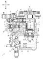
- FIG. 1 is a side sectional view showing a configuration of a fuel injection pump.
- the block diagram which shows the supply path of the lubricating oil in a diesel engine and a fuel injection pump. It is a partial cross section perspective view which shows the pump housing in which a transmission shaft and a transmission shaft are supported. It is a figure which shows the structure of the oil path of 1st embodiment.
- (A) It is a figure which shows the 1st opening part of an oil path
- the configuration of the fuel injection pump 1 will be described with reference to FIGS. 1 to 3. 1 and 2, the configuration of the fuel injection pump 1 is shown in a side view with a partial cross-sectional view.
- the fuel injection pump 1 supplies fuel to a fuel injection nozzle (not shown) of the diesel engine 30.
- the fuel injection pump 1 is a so-called distribution type fuel injection pump that distributes and supplies fuel to each cylinder of the diesel engine 30.
- the axial direction of the cam shaft 6 to be described later is defined as the front-rear direction
- the side on which the governor device 22 to be described later is disposed is the front
- the side on which the gear case 34 to be described is disposed. It shall be described as being defined as the rear.
- the fuel injection pump 1 includes a pump housing 2 and a pump head 3.
- the pump housing 2 is a structure that forms the lower half of the fuel injection pump 1. On the plane of the pump housing 2, a depression that is recessed downward in a substantially rectangular parallelepiped shape is formed.
- a cam chamber 4 is formed in the lower part of the pump housing 2. The cam chamber 4 is configured such that the cam shaft 6 is disposed and oil that has lubricated the inside of the pump housing 2 can be stored.
- a governor flange 2 ⁇ / b> A for attaching the governor device 22 is formed integrally with the pump housing 2.
- a cam shaft 6, a tappet 8, a transmission shaft 49, and the like are assembled to the pump housing 2.
- the pump head 3 is a structure that forms the upper half of the fuel injection pump 1.
- the pump head 3 is fixed on the pump housing 2.
- a space surrounded by a portion of the upper surface of the pump housing 2 forming a depression and the lower surface of the pump head 3 forms a rack chamber 5.
- the rack chamber 5 is disposed above the cam chamber 4.
- the pump head 3 is assembled with a plunger 12, a plunger barrel 13, a spring 14, a distribution shaft 15, a sleeve 17, a metering mechanism 18, and the like.
- the camshaft 6 is a long, substantially cylindrical member that extends horizontally across the cam chamber 4.
- the cam shaft 6 is rotatably supported by the pump housing 2 via a bearing or the like.
- a cam 6 ⁇ / b> A that drives the plunger 12 is fixed in the middle of the cam shaft 6.
- the tappet 8 is a substantially cylindrical member whose lower end is closed.
- the tappet 8 is slidably fitted into a tappet hole 2B formed in the pump housing 2.
- the tappet hole 2 ⁇ / b> B is a hole formed so as to communicate with the pump housing 2 provided between the cam chamber 4 and the rack chamber 5 in the vertical direction, and is generally closed by the tappet 8.
- the transmission shaft 49 is a substantially cylindrical member supported by the pump housing 2.
- the transmission shaft 49 is rotatably fitted in a transmission shaft hole 2 ⁇ / b> C formed in the pump housing 2.
- the transmission shaft hole 2 ⁇ / b> C is a hole formed so as to communicate the pump housing 2 provided between the cam chamber 4 and the rack chamber 5 in the vertical direction, and is generally closed by the transmission shaft 49.
- the transmission shaft 49 is disposed above the cam shaft 6 so that the axial direction thereof is a direction perpendicular to the cam shaft 6.
- the transmission shaft 49 has an upper end projecting into the rack chamber 5 and is connected to the distribution shaft 15 in the rack chamber 5.
- the transmission shaft 49 is interlocked with the cam shaft 6 via bevel gears 6B and 6C provided at the lower end thereof.
- the distribution shaft 15 is a substantially cylindrical member supported by the pump head 3.
- the distribution shaft 15 is rotatably fitted to a sleeve 17 fixed to the pump head 3.
- the distribution shaft 15 is disposed above the transmission shaft 49 so that its axial direction is perpendicular to the cam shaft 6.
- the distribution shaft 15 is interlocked with the transmission shaft 49.
- the metering mechanism 18 is a mechanism for adjusting the amount of fuel supplied from the fuel injection pump 1 to each cylinder of the diesel engine 30.
- the metering mechanism 18 includes a rack guide 19, a control rack 20, and a control sleeve 21.
- the rack guide 19 is a member that supports the control rack 20.
- the rack guide 19 is fixed in the front-rear direction on the upper surface of the rack chamber 5 and on the left side of the transmission shaft 49.
- the rack guide 19 is formed with a through hole for penetrating the control rack 20.
- the control rack 20 is a rod-shaped member.
- the control rack 20 is inserted into the through hole of the rack guide 19.
- the control rack 20 can slide in the through hole of the rack guide 19.
- One end of the control rack 20 is connected to the control sleeve 21, and the middle part of the control rack 20 is connected to a link 28 of a governor device 22 described later via a pin or the like.
- the control sleeve 21 is a substantially cylindrical member.
- the control sleeve 21 is fitted to the plunger 12 while being sandwiched between the plunger 12 and the spring receiver 16.
- the control sleeve 21 is rotatable in the circumferential direction along the inner peripheral surface of the spring receiver 16. At this time, the plunger 12 rotates integrally with the control sleeve 21 as the control sleeve 21 rotates.
- the governor device 22 is a device for operating the metering mechanism 18.
- the governor device 22 includes a support member 23, a plurality of centrifugal weights 24, 24,..., A slide body 25, a governor arm 26, a governor housing 27, a link 28, and the like.
- a governor housing 27 containing these members is attached to the governor flange 2A using bolts or the like.
- the distribution shaft 15 rotates via the bevel gears 6B and 6C and the transmission shaft 49 when the cam shaft 6 rotates.
- the fuel supplied to the distribution shaft 15 is supplied to the delivery valve 29 by the rotation of the distribution shaft 15.
- the fuel supplied to the delivery valve 29 is injected from the fuel injection nozzle of each cylinder through an injection pipe (not shown).
- the centrifugal weights 24, 24, which rotate integrally with the cam shaft 6 move the slide body 25 in accordance with the magnitude of the generated centrifugal force.
- the governor arm 26 is rotated around the support shaft by the movement of the slide body 25.
- the link 28 is moved by the rotation of the governor arm 26.
- the control rack 20 is moved in the through hole of the rack guide 19 by the movement of the link 28. As the control rack 20 moves, the control sleeve 21 and the plunger 12 are rotated in the circumferential direction. This makes it possible to adjust the amount of fuel supplied from the fuel injection pump 1 to each cylinder.
- Lubricating oil for the diesel engine 30 and the fuel injection pump 1 is stored in an oil pan 31.
- Lubricating oil stored in the oil pan 31 is sucked up by the lubricating oil pump 32 and supplied to the diesel engine 30 via an oil filter (not shown).
- the lubricating oil supplied to the diesel engine 30 is supplied to each part of the diesel engine 30 through a lubricating oil passage (not shown) formed in the diesel engine 30.
- the lubricating oil that has lubricated each part of the diesel engine 30 is returned to the oil pan 31.
- a part of the lubricating oil supplied to the diesel engine 30 is supplied to the fuel injection pump 1 through the lubricating oil passage 33.
- the lubricating oil supplied to the fuel injection pump 1 is discharged to the gear case 34 of the diesel engine 30 after lubricating the metering mechanism 18 and the camshaft 6 inside the pump housing 2.
- the lubricating oil discharged to the gear case 34 is returned to the oil pan 31.
- the lubricating oil passage 2D is an oil passage that pumps a part of the lubricating oil supplied into the pump housing 2 between the transmission shaft 49 and the transmission shaft hole 2C.
- the lubricating oil passage 2 ⁇ / b> D is provided penetrating from the wall surface of the tappet hole 2 ⁇ / b> B of the pump housing 2 toward the wall surface on the governor housing 27 side.
- a transmission shaft hole 2C communicates with the middle portion of the lubricating oil passage 2D.
- a part of the lubricating oil supplied from the diesel engine 30 into the fuel injection pump 1 is pumped between the transmission shaft 49 and the transmission shaft hole 2C through the lubricating oil passage 2D. It is possible to reduce frictional force and wear generated in the sliding motion between the members of the transmission shaft 49 and the transmission shaft hole 2C.
- a part of the lubricating oil pumped between the transmission shaft 49 and the transmission shaft hole 2 ⁇ / b> C is sent to the downstream side of the lubricating oil passage 2 ⁇ / b> D along with the rotation of the transmission shaft 49, and then supplied into the governor housing 27. .
- 5A shows the configuration of the transmission shaft 49 in a front view (viewed from the side of the second opening 42A described later) and a plan view.
- FIG. 5B the configuration of the transmission shaft 49 is shown. Is shown in a side view (viewed from the first opening 41A described later) and a plan view.
- FIG. 6A the first opening 41A is schematically shown in a side view
- FIG. 6B the groove 41 is schematically shown in a plan view.
- the transmission shaft 49 is a first embodiment according to the transmission shaft of the present invention.
- the transmission shaft 49 is formed with an oil passage 40 through which a part of the lubricating oil pumped to the lubricating oil passage 2D passes.
- the oil passage 40 is formed along the axial direction on the outer peripheral surface of the transmission shaft 49, and is opened in the groove 41 including the first opening 41 ⁇ / b> A and the wall portion 41 ⁇ / b> B (see FIG. 6) of the groove 41.
- a communication path 43 formed along the radial direction, and a supply hole 42 that communicates with the communication path 43 and is formed from a substantially axial center portion of the transmission shaft 49 to the second opening 42A.
- the first opening 41A of the oil passage 40 communicates with the lubricating oil passage 2D, and the second opening 42A of the oil passage 40 is formed on the outer peripheral surface of the upper portion of the transmission shaft 49 in the vicinity of the control rack 20 (see FIG. 4). ).
- a part of the lubricating oil pumped to the lubricating oil passage 2D is taken into the oil passage 40 through the first opening 41A, and then passes through the oil passage 40 to pass through the second opening 42A to the control rack 20. Is injected into.
- the groove 41 is formed in a vertically long shape on a predetermined outer peripheral surface of the transmission shaft 49.
- 41 A of 1st opening parts are comprised by arrange
- the first opening 41A for taking the lubricating oil from the lubricating oil passage 2D is configured by arranging the lower end portion of the groove 41 and the upper portion of the lubricating oil passage 2D so as to overlap in the vertical direction.
- the first opening 41A is a part of the groove 41, and the first opening 41A is formed by arranging the groove 41 and the lubricating oil passage 2D so as to partially overlap in the axial direction.
- the groove 41 is configured to communicate once with the upstream side of the lubricating oil passage 2D while the transmission shaft 49 rotates once.
- the first opening 41A constituting the groove 41 communicates with the lubricating oil passage 2D, so that a part of the lubricating oil pressure-fed through the lubricating oil passage 2D is part of the first opening 41A.
- Through the groove 41 intermittently.
- the amount of lubricating oil taken into the oil passage 40 through the first opening 41A during one rotation of the transmission shaft 49 is determined by the communication time and the communication area between the lubricating oil passage 2D and the first opening 41A.
- the communication path 43 is configured as a path that connects the groove 41 and the supply hole 42.
- the terminal portion (upper end portion) of the groove 41 and the start end portion (end portion on the axial center side of the transmission shaft 49) of the supply hole 42 are configured to have substantially the same height, and the start end portion of the supply hole 42 corresponds to the transmission shaft 49. It is provided so that it may be located in the substantially axial center part.
- the communication passage 43 is configured as a lateral hole provided toward the substantially axial center portion of the transmission shaft 49 provided at substantially the same height from the terminal portion of the groove 41.
- the communication path 43 is provided as a horizontal hole from a later-described wall portion 41B of the groove 41 toward the inside of the transmission shaft 49, and does not require complicated processing, so that the communication path 43 can be easily formed.
- the supply hole 42 is for spraying the lubricating oil taken in from the first opening 41 ⁇ / b> A through the communication path 43 to the control rack 20 provided on the upper surface of the rack chamber 5.
- the supply hole 42 is a hole formed from a second opening 42 ⁇ / b> A provided on the outer peripheral surface of the upper portion of the transmission shaft 49 near the control rack 20 toward the substantially axial center portion of the transmission shaft 49.
- the cross-sectional area of the supply hole 42 (cross-sectional area in the lubricating oil flow direction) is formed smaller than the cross-sectional area of the communication passage 43 (cross-sectional area in the lubricating oil flow direction).
- the cross-sectional area of the supply hole 42 is formed to be smaller than the cross-sectional area of the communication path 43, so that the pressure of the lubricating oil flowing through the supply hole 42 becomes a pressure that can be injected into the control rack 20.
- the supply hole 42 is constituted by a drill hole or the like.
- the supply hole 42 takes into account the relative position between the transmission shaft 49 and the control rack 20 and the pressure of the lubricant flowing in the supply hole 42 so that the lubricant can be sprayed onto the control rack 20. Inclined at a desired inclination angle from the second opening 42A formed on the outer peripheral surface of the upper part of the nearby transmission shaft 49 toward the inside of the transmission shaft 49.
- the second opening 42A is provided on the upper outer peripheral surface of the transmission shaft 49 and at a position where the lubricating oil can be injected into the control rack 20 at the time of injection.
- the second opening 42A extends from the first opening 41A to the transmission shaft 49. It is provided at a position that is rotationally displaced by a desired angle between approximately 90 degrees and 135 degrees (approximately 90 degrees in this embodiment) on the downstream side of the rotation.
- the lubricating oil passage 2D and the groove 41 communicate with each other, whereby oil is taken into the groove 41 via the first opening 41A.
- the lubricating oil taken into the groove 41 is supplied to the supply hole 42 through the communication path 43.
- the lubricating oil supplied to the supply hole 42 is sprayed at a predetermined position and sprayed to the control rack 20.
- a part of the lubricating oil in the lubricating oil passage 2 ⁇ / b> D is sprayed onto the control rack 20, so that water adhering to the control rack 20 is removed. That is, even when the temperature of the rack chamber 5 of the fuel injection pump 1 is equal to or lower than the dew point temperature of the blow-by gas, moisture does not adhere to the control rack 20 disposed inside the rack chamber 5. At the same time, even if the temperature of the rack chamber 5 falls below the freezing point, the starting failure of the diesel engine 30 due to the freezing of the control rack 20 can be prevented.
- the lower end of the first opening 41A constituting the groove 41 is formed in a substantially U shape.
- the lower end portion of the groove 41 is formed to be curved in a substantially U shape, and is arranged so that the lower end portion overlaps the lubricating oil passage 2D.
- the communication time and the communication area between the lubricating oil passage 2D and the first opening 41A can be reduced. Further, by allowing the portion of the groove 41 formed in a substantially U shape to communicate with the upper portion of the lubricating oil passage 2D, the communication time and the communication area between the lubricating oil passage 2D and the first opening 41A are further reduced. Can be made.
- the transmission shaft 49 is rotated at a high speed.
- the amount of lubricating oil taken in through one opening 41A can be adjusted. Therefore, not only the rotational speed of the transmission shaft 49 but also the amount of lubricating oil ejected through the supply hole 42 for a certain time can be made substantially constant.
- the shape of the groove 41 will be described with reference to FIG.
- the groove 41 includes a wall portion 41B that forms the bottom of the groove 41, and a side wall 41C that is formed substantially perpendicular to the wall portion 41B and is provided at each circumferential end of the wall portion 41B. That is, the groove 41 is formed in a substantially U shape in plan view.
- a communication passage 43 formed along the radial direction of the transmission shaft 49 is formed in the wall portion 41 ⁇ / b> B of the groove 41.
- the lubricating oil taken into the groove 41 from the first opening portion 41A is the wall portion 41B and the side wall 41C of the groove 41.
- a vortex is formed in the corner portion constituted by For this reason, since the lubricating oil tends to stay at the corners of the groove 41, leakage of the lubricating oil from the groove 41 between the members of the transmission shaft hole 2C and the transmission shaft 49 can be reduced, and the hydraulic pressure of the lubricating oil flowing in the groove 41 can be reduced. Can be maintained.
- the configuration of the transmission shaft of each embodiment shown in FIGS. 7 to 9 will be described.
- the oil passage provided in the transmission shaft of each embodiment shown in FIGS. 7 to 9 is configured such that the total length of the injection hole is shorter than that of the oil passage 40 of the embodiment shown in FIG.
- the configuration of the transmission shaft 59 will be described with reference to FIG.
- the transmission shaft 59 is a second embodiment according to the transmission shaft of the present invention.
- the transmission shaft 59 is formed with an oil passage 50 through which a part of the lubricating oil pumped to the lubricating oil passage 2D passes.
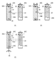
- FIG. 7A shows the configuration of the transmission shaft 59 in a front view (viewed from the second opening 52A described later) and a plan view
- FIG. 7B the configuration of the transmission shaft 59 is shown.
- the groove 51 is constituted by a longitudinal groove provided in the axial direction on the outer peripheral surface of the transmission shaft 59.
- 51 A of 1st opening parts are comprised by arrange
- the second opening 52A is rotationally displaced by a desired angle between approximately 90 degrees and 135 degrees (approximately 90 degrees in this embodiment) from the first opening 51A to the downstream side of the transmission shaft 59.
- the first opening 51A is a part of the groove 51, and the first opening 51A is formed by arranging the groove 51 and the lubricating oil passage 2D so as to partially overlap in the axial direction.
- the supply hole 52 is provided through the transmission shaft 59 from the second opening 52A provided on the outer peripheral surface of the upper portion of the transmission shaft 59 in the vicinity of the control rack 20 through the substantially axial center portion.
- the supply hole 52 is a hole 52 ⁇ / b> B constituted by a drill hole or the like from the second opening 52 ⁇ / b> A to an intermediate portion between the second opening 52 ⁇ / b> A and the substantially axial center of the transmission shaft 59.
- the intermediate portion between the second opening 52A and the substantially axial center portion of the transmission shaft 59 to the outer peripheral surface of the transmission shaft 59 facing the second opening 52A is formed as a through hole 52C.
- the through hole 52C is formed to have a larger diameter than the hole 52B.
- the hole 52B is formed from the second opening 52A, and the through hole 52C is formed from the outer peripheral surface of the transmission shaft 59 facing the second opening 52B in plan view.
- a communication path 53 that communicates with the upper end of the groove 51 is formed in the middle of the through hole 52C.
- the through hole 52C As described above, by forming the through hole 52C from the outer peripheral surface of the transmission shaft 59 facing the second opening 52A, the communication path 53 and the start end of the hole 52B can be easily communicated with each other, and the supply hole
- the oil passage 50 can be configured such that the overall length of the hole 52B that configures 52 is shortened. Further, the opening on the outer peripheral surface of the transmission shaft 59 facing the second opening 52A is substantially sealed by the transmission shaft hole 2C, so that the hydraulic pressure of the lubricating oil flowing in the oil passage 50 can be maintained.
- the length of the hole 52 ⁇ / b> B constituting the supply hole 52 is configured to be short, thereby facilitating processing and further increasing the life of the processing tool. Can do.
- the configuration of the transmission shaft 69 will be described with reference to FIG.
- the transmission shaft 69 is a third embodiment according to the transmission shaft of the present invention.
- the transmission shaft 69 is formed with an oil passage 60 through which a part of the lubricating oil pumped to the lubricating oil passage 2D passes.
- FIG. 8A shows the configuration of the transmission shaft 69 in a front view (viewed from the second opening 62A described later) and a plan view
- FIG. 8B shows the configuration of the transmission shaft 69 is shown. Is shown in a side view (viewed from the first opening 61A described later) and a plan view.
- FIG. 8C shows a plan view of a longitudinal groove 61 ⁇ / b> C constituting an oil passage 60 described later.
- the supply hole 62 is provided from the second opening 62A provided on the outer peripheral surface of the upper portion of the transmission shaft 69 in the vicinity of the control rack 20 to the substantially axial center portion.
- the start end of the supply hole 62 (the end on the axial center side of the transmission shaft 69) is an intermediate portion between the upper outer peripheral surface (second opening 62A) of the transmission shaft 69 and the substantially axial center of the transmission shaft 69 in plan view.
- the supply hole 62 is constituted by a drill hole or the like.
- the groove 61 includes a vertical groove 61C provided in the axial direction on the outer peripheral surface of the transmission shaft 69, and a horizontal groove 61B provided at the lower end portion of the vertical groove 61C so as to partially overlap the circumferential direction of the transmission shaft 69. . 61 A of 1st opening parts are comprised by providing the horizontal groove 61B so that it may connect with lubricating oil channel
- the horizontal groove 61B is arranged so that the rotation downstream end portion thereof overlaps with the rotation upstream end portion of the vertical groove 61C.
- the longitudinal groove 61C is arranged on the supply hole 62 side as compared with the groove 41 of the embodiment shown in FIG.
- a horizontal hole is provided as a communication path 63 from the upper end of the vertical groove 61 ⁇ / b> C toward the start end of the supply hole 62.
- the first opening 61A is a part of the lateral groove 61B, and the first opening 61A is formed by arranging the lateral groove 61B and the lubricating oil passage 2D so as to partially overlap in the axial direction.
- the shape of the longitudinal groove 61C will be described with reference to FIG.
- the vertical groove 61C is formed by a wall portion 61D that forms the bottom of the vertical groove 61C, and a side wall 61E that is formed substantially perpendicular to the wall portion 61D and is provided only at the upstream end in the rotational direction of the wall portion 61D. Composed. That is, the longitudinal groove 61C is formed in a substantially L shape in plan view.
- the communication path 63 is configured by a horizontal hole formed along the radial direction of the transmission shaft 69 from the wall portion 61D of the vertical groove 61C.
- the lubricating oil taken into the vertical groove 61C from the first opening 61A is caused by the wall 61D and the side wall 61E of the vertical groove 61C.
- a vortex is formed at the corners formed.
- leakage of the lubricating oil from the vertical groove 61C between the members of the transmission shaft hole 2C and the transmission shaft 69 can be reduced, and the lubricating oil flowing into the vertical groove 61C.
- the oil pressure can be maintained.
- the communication path 63 is provided as a horizontal hole from the wall portion 61D of the vertical groove 61C toward the inside of the transmission shaft 69, and the communication path 63 can be easily formed without requiring complicated processing.
- the horizontal groove 61B is provided so as to overlap the lower end portion of the vertical groove 61C in the circumferential direction
- the first opening 61A is configured so that the horizontal groove 61B and the lubricating oil passage 2D communicate with each other, whereby the second opening
- the part 62A is provided at a position that is rotationally displaced by a desired angle between approximately 90 degrees and 135 degrees (approximately 90 degrees in the present embodiment) on the downstream side of the transmission shaft 69 from the first opening 61A. Therefore, the lubricating oil can be sprayed from the second opening 62A to the control rack 20 at a desired position.
- the configuration of the transmission shaft 79 will be described with reference to FIG.
- the transmission shaft 79 is a fourth embodiment according to the transmission shaft of the present invention.
- the transmission shaft 79 is formed with an oil passage 70 through which a part of the lubricating oil pumped to the lubricating oil passage 2D passes.
- FIG. 9A shows the configuration of the transmission shaft 79 in a front view (viewed from the second opening 72A described later) and a plan view.
- FIG. 9B the configuration of the transmission shaft 79 is shown.
- FIG. 9C shows the configuration of the transmission shaft 79 from a direction orthogonal to the axial direction of the supply hole 72 described later. This is shown in the figure.
- the supply hole 72 is provided from the second opening 72A provided on the outer peripheral surface of the upper portion of the transmission shaft 79 in the vicinity of the control rack 20 toward the substantially axial center portion.
- the start end portion of the supply hole 72 (the end portion on the axial center side of the transmission shaft 79) is an intermediate portion between the outer peripheral surface (second opening 72A) on the transmission shaft 79 and the substantially axial center portion of the transmission shaft 79 in plan view.
- the supply hole 72 is arranged on the rotation downstream side of the transmission shaft 79 as compared with the supply hole 42 of the embodiment shown in FIG.
- the supply hole 72 is constituted by a drill hole or the like.
- the groove 71 is constituted by a longitudinal groove provided in the axial direction on the outer peripheral surface of the transmission shaft 79.
- 71 A of 1st opening parts are comprised by arrange
- the groove 71 is arranged on the supply hole 72 side as compared with the groove 41 of the embodiment shown in FIG.
- a lateral hole is provided as a communication path 73 from the upper end portion of the groove 71 toward the start end portion of the supply hole 72.
- the first opening 71A is a part of the groove 71, and the first opening 71A is formed by arranging the groove 71 and the lubricating oil passage 2D so as to partially overlap in the axial direction.
- the shape of the groove 71 will be described with reference to FIG.
- the groove 71 is formed in a substantially L shape in plan view, similarly to the longitudinal groove 61C of the embodiment shown in FIG.
- the groove 71 includes a wall portion 71B that forms the bottom of the groove 71, and a side wall 71C that is formed substantially perpendicular to the wall portion 71B and is provided only at an end portion on the upstream side in the rotation direction of the wall portion 71B.
- the That is, the groove 71 is formed in a substantially L shape in plan view.
- the communication path 73 is configured by a horizontal hole formed along the radial direction of the transmission shaft 79 from the wall portion 71 ⁇ / b> B of the groove 71.
- the lubricating oil taken into the groove 71 from the first opening 71A is constituted by the wall portion 71B and the side wall 71C of the groove 71.
- a vortex is formed at the corner.
- leakage of the lubricating oil from the groove 71 between the members of the transmission shaft hole 2C and the transmission shaft 79 can be reduced, and the hydraulic pressure of the lubricating oil flowing in the groove 71 can be reduced. Can be maintained.
- the communication path 73 is provided as a horizontal hole from the wall portion 71B of the groove 71 toward the inside of the transmission shaft 79, and the communication path 73 can be easily formed without requiring complicated processing.
- the groove 71 and the communication passage 73 of the present embodiment are configured to have a longer overall length, and therefore the second opening 72A is connected to the transmission shaft from the first opening 71A.
- 79 is provided at a position that is rotationally displaced by a desired angle between approximately 90 degrees and 135 degrees (approximately 120 degrees in this embodiment) on the downstream side of the rotation of 79, so that the second opening 72 ⁇ / b> A at the desired position.
- Lubricating oil can be sprayed onto the control rack 20.
- the processing can be facilitated and the life of the processing tool can be increased.
- the configuration of the transmission shaft of each embodiment shown in FIG. 10 will be described.
- the oil passage provided in the transmission shaft of each embodiment shown in FIG. 10 is constituted by a lateral hole provided toward the substantially shaft center portion of the transmission shaft, not the groove in which the first opening is provided in the outer peripheral surface of the transmission shaft.
- a communication path that connects the horizontal hole and the supply hole is formed by a vertical hole that is provided along the axis from the bottom of the transmission shaft.
- the configuration of the transmission shaft 89A will be described with reference to FIG.
- the transmission shaft 89A is a fifth embodiment according to the transmission shaft of the present invention.
- the transmission shaft 89A is formed with an oil passage 80A through which a part of the lubricating oil pumped to the lubricating oil passage 2D passes.
- the configuration of the transmission shaft 89A is represented by a front view (viewed from the second opening 82A described later) and a side view (viewed from the first opening 81A described later). Yes.
- the supply hole 82 is provided from the second opening 82A provided on the outer peripheral surface of the upper part of the transmission shaft 89A in the vicinity of the control rack 20 toward the substantially axial center portion.
- the start end portion of the supply hole 82 (the end portion on the axial center side of the transmission shaft 89A) communicates with a vertical hole 83 described later.
- the transmission shaft 89A is provided with a lateral hole 81 from its outer peripheral surface toward the axis.
- the first opening 81A is formed by arranging the lateral hole 81 so as to overlap the lubricating oil passage 2D.
- the transmission shaft 89A is provided with a vertical hole 83 along the axis from the bottom surface.
- the vertical hole 83 is provided so as to penetrate the bottom portion of the transmission shaft 89, and is configured to be closed by the sealing plug 84.
- a terminal portion of the horizontal hole 81 is communicated with a middle portion of the vertical hole 83.
- the hydraulic pressure of the lubricating oil flowing in the vertical hole 83 can be maintained by closing the bottom of the vertical hole 83 with the sealing plug 84. Further, the vertical hole 83 is provided from the bottom surface of the transmission shaft 89A toward the inside of the transmission shaft 89A, and the vertical hole 83 can be easily formed without requiring complicated processing.
- the configuration of the transmission shaft 89B will be described with reference to FIG.
- the transmission shaft 89B is a sixth embodiment according to the transmission shaft of the present invention.
- the transmission shaft 89B is formed with an oil passage 80B through which a part of the lubricating oil pumped to the lubricating oil passage 2D passes.
- the configuration of the transmission shaft 89B is represented by a front view (viewed from the second opening 82A described later) and a side view (viewed from the first opening 81A described later). Yes.
- the oil passage 80B is configured by providing a pressure regulating valve 85 instead of the sealing plug 84 in the configuration of the oil passage 80A of the embodiment shown in FIG.
- a pressure regulating valve 85 By providing the pressure regulating valve 85 at the bottom of the vertical hole 83, when the hydraulic pressure of the lubricating oil flowing in the oil passage 80B is too high, a part thereof is discharged from the bottom of the transmission shaft 89B to the outside. .
- the pressure regulating valve 85 the amount of lubricating oil sprayed onto the control rack 20 can be made constant.
- the configuration of the transmission shaft 89C will be described with reference to FIG.
- the transmission shaft 89C is a seventh embodiment according to the transmission shaft of the present invention.
- the transmission shaft 89C is formed with an oil passage 80C through which a part of the lubricating oil pumped to the lubricating oil passage 2D passes.
- the configuration of the transmission shaft 89C is represented by a front view (viewed from the second opening 82A described later) and a side view (viewed from the first opening 81A described later). Yes.
- the oil passage 80C is provided with a throttle valve 87 that opens and closes the valve using the centrifugal force of the centrifugal weight 86 instead of the sealing plug 84 in the configuration of the oil passage 80A of the embodiment shown in FIG. Consists of.
- the throttle valve 87 is configured such that the valve can be opened and closed by changing the centrifugal force of the centrifugal weight 86 by the rotational speed of the transmission shaft 89C and sliding the valve body. In the present embodiment, the valve is closed when the rotational speed of the transmission shaft 89C becomes high.
- the valve can be opened and closed by the rotational speed of the transmission shaft 89C, so that the lubricating oil injected to the control rack 20 is independent of the rotational speed of the transmission shaft 89C, that is, the rotational speed of the diesel engine 30.
- the amount can be constant.
- the configuration of the transmission shaft of each embodiment shown in FIG. 11 will be described.
- the oil passage provided in the transmission shaft of each embodiment shown in FIG. 11 is configured by a groove provided in the outer peripheral surface of the transmission shaft.
- the configuration of the transmission shaft 99A will be described with reference to FIG.
- the transmission shaft 99A is an eighth embodiment according to the transmission shaft of the present invention.
- the transmission shaft 99A is formed with an oil passage 90A through which a part of the lubricating oil pumped to the lubricating oil passage 2D passes.
- the configuration of the transmission shaft 99A is represented by a front view (viewed from the second opening 93A described later) and a side view (viewed from the first opening 91A described later). Yes.
- the first opening 91A is configured by arranging the lubricating oil passage 2D and the longitudinal groove 91 provided on the outer peripheral surface of the transmission shaft 99A so as to partially overlap in the axial direction.
- a lower portion of a circumferential groove 92 provided along the circumferential direction of the transmission shaft 99A is arranged so as to overlap in the axial direction.
- An upper portion of the circumferential groove 92 is disposed so that a lower portion of the vertical groove 93 provided toward the upper outer peripheral surface of the transmission shaft 99A overlaps in the axial direction.
- the first opening 91A is a part of the vertical groove 91, and the first opening 91A is formed by arranging the vertical groove 91 and the lubricating oil passage 2D so as to partially overlap in the axial direction. It is formed.
- the lubricating oil taken in from the first opening 91 ⁇ / b> A is taken into the circumferential groove 92 through the longitudinal groove 91.
- Lubricating oil taken into the circumferential groove 92 flows into the vertical groove 93 and enters the control rack 20 from the second opening 93A that constitutes the upper end of the vertical groove 93 (between the members of the transmission shaft 99A and the transmission shaft hole 2C). It is injected towards.
- the shape of the vertical groove 93 is set so that the pressure of the lubricating oil flowing through the vertical groove 93 becomes a pressure that can be injected into the control rack 20 by reducing the depth of the groove, for example.
- the oil passage 90A can be easily formed by forming the oil passage by the groove formed on the outer peripheral surface of the transmission shaft 99A.
- the configuration of the transmission shaft 99B will be described with reference to FIG.
- the transmission shaft 99B is a ninth embodiment according to the transmission shaft of the present invention.
- the transmission shaft 99B is formed with an oil passage 90B through which a part of the lubricating oil pumped to the lubricating oil passage 2D passes.
- the configuration of the transmission shaft 99B is represented by a front view (viewed from the second opening 95A described later) and a side view (viewed from the first opening 94A described later). Yes.
- the first opening 94A is configured by arranging a circumferential groove 94 provided along the circumferential direction of the transmission shaft 99B so as to overlap the lubricating oil passage 2D in the axial direction.
- a vertical groove 95 provided toward the upper outer peripheral surface of the transmission shaft 99B is provided on the upper part of the circumferential groove 94 so as to partially overlap in the axial direction.
- the first opening 91A is formed by arranging the circumferential groove 94 and the lubricating oil passage 2D so as to overlap in the axial direction.
- the lubricating oil taken from the first opening 94 ⁇ / b> A is taken into the vertical groove 95 via the circumferential groove 94.
- Lubricating oil taken into the vertical groove 95 is sprayed toward the control rack 20 from the second opening 95A constituting the upper end of the vertical groove 95 (between the members of the transmission shaft 99B and the transmission shaft hole 2C).
- the shape of the vertical groove 95 is set so that the pressure of the lubricating oil flowing through the vertical groove 95 becomes a pressure that can be injected into the control rack 20 by reducing the depth of the groove, for example.
- the oil passage 90B can be easily formed by forming the oil passage by the groove formed on the outer peripheral surface of the transmission shaft 99B. Further, since the lower portion of the circumferential groove 94 is always in communication with the lubricating oil passage 2D, the control rack 20 can be constantly lubricated.
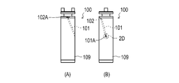
- the configuration of the transmission shaft 109 will be described with reference to FIG.
- the transmission shaft 109 is a tenth embodiment according to the transmission shaft of the present invention.
- the transmission shaft 109 is formed with an oil passage 100 through which a part of the lubricating oil pumped to the lubricating oil passage 2D passes.
- FIG. 12A the configuration of the transmission shaft 109 is shown in a front view (as viewed from the second opening 102A described later), and in FIG. 12B, it is viewed in a side view (a first opening described later). (Viewed from the part 101A side) and a plan view.
- the supply hole 102 is provided from the second opening 102A provided on the outer peripheral surface of the upper part of the transmission shaft 109 toward the substantially axial center portion.
- 101 A of 1st opening parts are provided with the through-hole 101 penetrated from the outer peripheral surface of the transmission shaft 109 which can be connected with the lubricating oil channel
- the start end portion of the supply hole 012 communicates with the end portion of the through hole 101.
- the oil passage 100 is formed inside the transmission shaft 109, the oil pressure of the lubricating oil flowing through the oil passage 100 can be maintained.
- the oil path of each embodiment shown above is comprised by providing a groove
- the oil passage may be formed by providing a groove or a hole in the pump housing 2 that rotatably supports the transmission shaft 109.
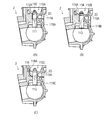
- each embodiment shown in FIG. 13 The structure of the transmission shaft and pump housing 2 of each embodiment shown in FIG. 13 will be described.
- the oil passage of each embodiment shown in FIG. 13 is configured by providing a groove and a hole only in the transmission shaft and the pump housing 2 or the pump housing 2.
- the configuration of the eleventh embodiment of the oil passage formed in the transmission shaft 119A and the pump housing 2 will be described with reference to FIG.
- the transmission shaft 119A and the pump housing 2 are formed with an oil passage 110A through which a part of the lubricating oil pumped to the lubricating oil passage 2D passes.
- FIG. 13A the configuration of the transmission shaft 119A and the pump housing 2 is shown by a partial cross-sectional view of the pump housing 2 as viewed from the front-rear direction.
- the 111 A of 1st opening parts are comprised by arrange
- a vertical groove 112 is provided on the inner peripheral surface of the transmission shaft hole 2C so as to partially overlap the circumferential groove 111 in the axial direction.
- the vertical groove 112 is formed from the upper part of the circumferential groove 111 toward the bottom surface of the rack chamber 5.
- the first opening 111A is formed by arranging the circumferential groove 111 and the lubricating oil passage 2D so as to overlap in the axial direction.
- the lubricating oil taken from the first opening 111A is taken into the vertical groove 112 through the circumferential groove 111.
- Lubricating oil taken into the vertical groove 112 is sprayed toward the control rack 20 from the second opening 112A constituting the upper end of the vertical groove 112 (between the members of the transmission shaft 119A and the transmission shaft hole 2C).
- the configuration of the twelfth embodiment of the oil passage formed in the pump housing 2 will be described with reference to FIG.
- the pump housing 2 is formed with an oil passage 110B through which a part of the lubricating oil pumped to the lubricating oil passage 2D passes.
- FIG. 13A the configuration of the transmission shaft 119B and the pump housing 2 is shown by a partial cross-sectional view of the pump housing 2 as viewed from the front-rear direction.
- the first opening 113A is configured by arranging a circumferential groove 113 provided on the inner circumferential surface along the circumferential direction of the transmission shaft hole 2C so as to partially overlap the lubricating oil passage 2D in the vertical direction.
- a vertical groove 114 is provided on the inner peripheral surface of the transmission shaft hole 2 ⁇ / b> C so as to partially overlap the circumferential groove 113 in the vertical direction.
- the vertical groove 114 is formed from the upper part of the circumferential groove 113 toward the bottom surface of the rack chamber 5.
- the first opening 113A is formed by arranging the circumferential groove 113 and the lubricating oil passage 2D so as to overlap in the axial direction.
- the lubricating oil taken from the first opening 113A is taken into the vertical groove 114 through the circumferential groove 113.
- the oil taken into the vertical groove 114 is sprayed toward the control rack 20 from the second opening 114A constituting the upper end portion of the vertical groove 114 (between the members of the transmission shaft 119B and the transmission shaft hole 2C).
- the configuration of the thirteenth embodiment of the oil passage formed in the pump housing 2 will be described with reference to FIG.
- the pump housing 2 is formed with an oil passage 110C through which a part of the lubricating oil pumped to the lubricating oil passage 2D passes.
- FIG. 13A the configuration of the transmission shaft 119C and the pump housing 2 is shown by a partial cross-sectional view of the pump housing 2 as viewed from the front-rear direction.
- a of 1st opening parts are comprised by arrange
- a supply hole 116 is provided in the pump housing 2 from the circumferential groove 115 toward the bottom surface of the rack chamber 5.
- the first opening 115A is formed by arranging the circumferential groove 115 and the lubricating oil passage 2D so as to overlap in the axial direction.
- the lubricating oil taken from the first opening 115 ⁇ / b> A is taken into the supply hole 116 through the circumferential groove 115.
- the oil taken into the supply hole 116 is sprayed toward the control rack 20 from the second opening 116 ⁇ / b> A that forms the upper end of the supply hole 116.
- a through hole may be provided from the governor housing 27 side directly toward the supply hole 116 provided in the pump housing 2 without using the lubricating oil passage 2D.
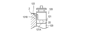
- the configuration of the fourteenth embodiment of the oil passage formed in the pump housing 2 will be described with reference to FIG.
- the pump housing 2 is formed with an oil passage 120 through which a part of the lubricating oil pumped to the lubricating oil passage 2D passes.
- FIG. 14 the configuration of the transmission shaft 129 and the pump housing 2 is shown by a partial cross-sectional view of the pump housing 2 as viewed from the front-rear direction.
- the first opening 121A is configured such that a circumferential groove 121 provided on the outer peripheral surface along the circumferential direction of the transmission shaft 129 is arranged so as to partially overlap the lubricating oil passage 2D in the axial direction.
- the circumferential groove 121 is provided with a convex portion 121B whose groove width increases in the axial direction.
- the pump housing 2 is provided with a supply hole 122 that can communicate with the convex portion 121B.
- the supply hole 122 is provided in the pump housing 2 so as to penetrate a bottom surface constituting the rack chamber 5 with a surface on the transmission shaft hole 2C side of the pump housing 2 at a desired inclination angle.
- the first opening 121A is formed by arranging the circumferential groove 121 and the lubricating oil passage 2D so as to overlap in the axial direction.
- an oil passage can be formed by forming a groove or a hole in the pump housing 2.
- the pump housing 2 is manufactured by casting, so that it is not necessary to perform processing such as cutting and can be easily formed.
- the present invention can be used for a fuel injection pump.
Landscapes
- Engineering & Computer Science (AREA)
- Health & Medical Sciences (AREA)
- Life Sciences & Earth Sciences (AREA)
- General Engineering & Computer Science (AREA)
- Mechanical Engineering (AREA)
- Combustion & Propulsion (AREA)
- Chemical & Material Sciences (AREA)
- Physics & Mathematics (AREA)
- General Health & Medical Sciences (AREA)
- Medical Informatics (AREA)
- Public Health (AREA)
- Molecular Biology (AREA)
- Heart & Thoracic Surgery (AREA)
- Biomedical Technology (AREA)
- Surgery (AREA)
- Pathology (AREA)
- Biophysics (AREA)
- Animal Behavior & Ethology (AREA)
- Veterinary Medicine (AREA)
- Signal Processing (AREA)
- Physiology (AREA)
- Nuclear Medicine, Radiotherapy & Molecular Imaging (AREA)
- Radiology & Medical Imaging (AREA)
- Computer Vision & Pattern Recognition (AREA)
- Cardiology (AREA)
- Artificial Intelligence (AREA)
- Psychiatry (AREA)
- Computer Security & Cryptography (AREA)
- Epidemiology (AREA)
- Computer Networks & Wireless Communication (AREA)
- General Physics & Mathematics (AREA)
- Primary Health Care (AREA)
- Hematology (AREA)
- Theoretical Computer Science (AREA)
- High Energy & Nuclear Physics (AREA)
- Mathematical Physics (AREA)
- Computing Systems (AREA)
- Condensed Matter Physics & Semiconductors (AREA)
- Computer Hardware Design (AREA)
- Multimedia (AREA)
Abstract
Description
なお、図1及び図2では、燃料噴射ポンプ1の構成を一部断面視とした側面視によって表している。
燃料噴射ポンプ1は、燃料をディーゼルエンジン30の図示しない燃料噴射ノズルに供給するものである。燃料噴射ポンプ1は、ディーゼルエンジン30の各気筒に燃料を分配して供給する、いわゆる分配型の燃料噴射ポンプである。
本発明に係る燃料噴射ポンプ1では、後述のカム軸6の軸線方向を前後方向と規定するとともに、後述のガバナ装置22が配置される側を前方、後述のギアケース34が配置される側を後方と規定して、説明を行うものとする。
カム軸6が回転すると、カム6Aに当接しているタペット8がタペット孔2B内を上下方向に往復運動する。これにともなって、プランジャ12がプランジャバレル13内を上下方向に往復運動する。これにより、燃料は、加圧室13A内に吸入および加圧された後に分配軸15に供給される。
ディーゼルエンジン30および燃料噴射ポンプ1の潤滑油は、オイルパン31に貯留される。オイルパン31に貯留されている潤滑油は、潤滑油ポンプ32によって吸い上げられ、図示しないオイルフィルタ等を介してディーゼルエンジン30に供給される。ディーゼルエンジン30に供給された潤滑油は、ディーゼルエンジン30に形成される図示しない潤滑油通路を介してディーゼルエンジン30の各部に供給される。ディーゼルエンジン30の各部を潤滑した潤滑油は、オイルパン31に戻される。
なお、図5(A)では、伝達軸49の構成を正面視(後述の第二開口部42A側からみた)及び平面視にて表しており、図5(B)では、伝達軸49の構成を側面視(後述の第一開口部41A側からみた)及び平面視にて表している。
溝41は、溝41の底を形成する壁部41Bと、壁部41Bに対して略垂直に形成され、壁部41Bの周方向端部にそれぞれ設けられる側壁41Cと、によって構成される。つまり、溝41は、平面視において、略コの字状に形成される。溝41の壁部41Bには、伝達軸49の径方向に沿って形成される連通路43が形成される。
図7から図9に示す各実施形態の伝達軸に設けられる油路は、図5に示す実施形態の油路40と比べて、噴射孔の全長が短くなるように構成される。
縦溝61Cは、縦溝61Cの底を形成する壁部61Dと、壁部61Dに対して略垂直に形成され、壁部61Dの回転方向上流側の端部にのみ設けられる側壁61Eと、によって構成される。つまり、縦溝61Cは、平面視において、略L字状に形成される。連通路63は、縦溝61Cの壁部61Dから伝達軸69の径方向に沿って形成される横孔によって構成される。
溝71は、図8(C)に示す実施形態の縦溝61Cと同様に、平面視において略L字状に形成される。溝71は、溝71の底を形成する壁部71Bと、壁部71Bに対して略垂直に形成され、壁部71Bの回転方向上流側の端部にのみ設けられる側壁71Cと、によって構成される。つまり、溝71は、平面視において、略L字状に形成される。連通路73は、溝71の壁部71Bから伝達軸79の径方向に沿って形成される横孔によって構成される。
図10に示す各実施形態の伝達軸に設けられる油路は、第一開口部が伝達軸の外周面に設けられる溝ではなく、伝達軸の略軸心部に向けて設けられる横孔によって構成され、横孔と供給孔とを連通する連通路が伝達軸の底部から軸心に沿って設けられる縦孔によって形成される。
図11に示す各実施形態の伝達軸に設けられる油路は、伝達軸の外周面に設けられる溝によって構成される。
縦溝93の形状は、例えば溝の深さを浅くすることで、縦溝93を流れる潤滑油の圧力をコントロールラック20に噴射可能な圧力となるように設定される。
縦溝95の形状は、例えば溝の深さを浅くすることで、縦溝95を流れる潤滑油の圧力をコントロールラック20に噴射可能な圧力となるように設定される。
図13に示す各実施形態の油路は、伝達軸及びポンプハウジング2、または、ポンプハウジング2にのみ溝や孔を設けることで構成される。
なお、潤滑油通路2Dを介さないで、ガバナハウジング27側から直接ポンプハウジング2の内部に設けられる供給孔116に向けて貫通孔を設けてもよい。
2 ポンプハウジング
2A ガバナフランジ
2C 伝達軸孔
2D 潤滑油通路
3 ポンプヘッド
4 カム室
5 ラック室
15 分配軸
20 コントロールラック
30 ディーゼルエンジン
32 潤滑油ポンプ
40 油路
41 溝
41A 第一開口部
41B 壁部
41C 側壁
42 供給孔
42A 第二開口部
43 連通路
49 伝達軸
Claims (4)
- エンジンに設けられる燃料噴射ポンプであって、
ポンプヘッドとポンプハウジングとの間に形成されるラック室に配置され、燃料噴射量を調整するコントロールラックと、
前記ポンプハウジングに形成される伝達軸孔に回転支持される伝達軸と、
前記ポンプハウジングに形成され、前記伝達軸と前記伝達軸孔との間に潤滑油を圧送する潤滑油通路と、
を備え、
前記伝達軸には、前記潤滑油通路に圧送される潤滑油の一部が通過する油路が形成され、前記油路の第一開口部は、前記潤滑油通路と連通され、前記油路の第二開口部は、前記コントロールラック近傍の前記伝達軸上部の外周面に形成される、
燃料噴射ポンプ。 - 前記油路は、
前記伝達軸の外周面に軸方向に沿って形成され、前記第一開口部を含む溝と、
前記溝の壁部に開口され、前記伝達軸の径方向に沿って形成される連通路と、
前記連通路と連通され、前記伝達軸の略軸心部から前記第二開口部まで形成される供給孔と、
を備える、
請求項1に記載の燃料噴射ポンプ。 - 前記溝は、前記壁部に対して垂直に形成される少なくとも一つの側壁が形成される、
請求項2に記載の燃料噴射ポンプ。 - 前記溝の開口部の下端部は、略U字形状に形成される、
請求項3に記載の燃料噴射ポンプ。
Priority Applications (5)
| Application Number | Priority Date | Filing Date | Title |
|---|---|---|---|
| CN201680067156.9A CN108291515B (zh) | 2015-11-26 | 2016-11-11 | 燃料喷射泵 |
| KR1020187017604A KR102096198B1 (ko) | 2015-11-26 | 2016-11-11 | 연료 분사 펌프 |
| KR1020207007019A KR102443622B1 (ko) | 2015-11-26 | 2016-11-11 | 연료 분사 펌프 |
| EP16868414.0A EP3382194B1 (en) | 2015-11-26 | 2016-11-11 | Fuel injection pump |
| US15/779,477 US10718305B2 (en) | 2015-11-26 | 2016-11-11 | Fuel injection pump |
Applications Claiming Priority (2)
| Application Number | Priority Date | Filing Date | Title |
|---|---|---|---|
| JP2015231174A JP6411313B2 (ja) | 2015-11-26 | 2015-11-26 | 燃料噴射ポンプ |
| JP2015-231174 | 2015-11-26 |
Publications (1)
| Publication Number | Publication Date |
|---|---|
| WO2017090466A1 true WO2017090466A1 (ja) | 2017-06-01 |
Family
ID=58763129
Family Applications (1)
| Application Number | Title | Priority Date | Filing Date |
|---|---|---|---|
| PCT/JP2016/083546 Ceased WO2017090466A1 (ja) | 2015-11-26 | 2016-11-11 | 燃料噴射ポンプ |
Country Status (6)
| Country | Link |
|---|---|
| US (2) | US10718305B2 (ja) |
| EP (1) | EP3382194B1 (ja) |
| JP (1) | JP6411313B2 (ja) |
| KR (2) | KR102443622B1 (ja) |
| CN (2) | CN111894779A (ja) |
| WO (1) | WO2017090466A1 (ja) |
Families Citing this family (4)
| Publication number | Priority date | Publication date | Assignee | Title |
|---|---|---|---|---|
| JP6411313B2 (ja) * | 2015-11-26 | 2018-10-24 | ヤンマー株式会社 | 燃料噴射ポンプ |
| US12037427B2 (en) | 2018-09-28 | 2024-07-16 | Nippon Steel Chemical & Material Co., Ltd. | Polyfunctional vinyl aromatic copolymer and method for manufacturing same, copolymer rubber obtained therefrom, rubber composition, rubber crosslinked material, and tire member |
| JP7636324B2 (ja) | 2019-06-25 | 2025-02-26 | 日鉄ケミカル&マテリアル株式会社 | 変性ビニル芳香族系共重合体及びその製造方法、それから得られる変性共役ジエン系共重合体、その組成物、ゴム架橋物及びタイヤ部材 |
| EP4442713A4 (en) | 2021-12-03 | 2025-12-03 | Nippon Steel Chemical & Mat Co Ltd | MODIFIED VINYL AROMATIC COPOLYMER, ASSOCIATED PRODUCTION PROCESS, MODIFIED CONJUGATED DIENE COPOLYMER OBTAINED FROM THEREOF, RESIN COMPOSITION, CROSS-CUT RESIN AND STRUCTURAL ELEMENT |
Citations (6)
| Publication number | Priority date | Publication date | Assignee | Title |
|---|---|---|---|---|
| JPS59131970U (ja) * | 1983-02-24 | 1984-09-04 | 宇部興産株式会社 | 内燃機関の燃料噴射ポンプ |
| JPS63125121U (ja) * | 1987-02-06 | 1988-08-16 | ||
| JPH04123367U (ja) * | 1991-04-22 | 1992-11-09 | 日野自動車工業株式会社 | 燃料噴射ポンプ |
| JPH06330833A (ja) * | 1993-05-24 | 1994-11-29 | Yanmar Diesel Engine Co Ltd | 燃料噴射ポンプ |
| JP2007303313A (ja) * | 2006-05-09 | 2007-11-22 | Yanmar Co Ltd | 燃料噴射ポンプ |
| JP2013204500A (ja) | 2012-03-28 | 2013-10-07 | Yanmar Co Ltd | 燃料噴射ポンプ |
Family Cites Families (39)
| Publication number | Priority date | Publication date | Assignee | Title |
|---|---|---|---|---|
| US2363576A (en) * | 1943-09-25 | 1944-11-28 | Devorak Raymond John | Fuel control valve for diesel engines |
| US2503458A (en) * | 1946-02-11 | 1950-04-11 | Diesel Power Inc | Fuel injection pump |
| US2828727A (en) * | 1953-03-05 | 1958-04-01 | Bosch Arma Corp | Fuel injection pump |
| US3744465A (en) * | 1972-01-24 | 1973-07-10 | Ambac Ind | Hydraulic shuttle vavle for fuel injection pumps |
| US4531494A (en) * | 1984-03-27 | 1985-07-30 | Caterpillar Tractor Co. | Distributor fuel injection pump having a nutator pump subassembly |
| JPH0212299Y2 (ja) * | 1984-12-28 | 1990-04-06 | ||
| US5152271A (en) * | 1985-07-15 | 1992-10-06 | Osamu Matsumura | Fuel injection apparatus |
| US5000668A (en) * | 1988-04-27 | 1991-03-19 | Diesel Kiki Co., Ltd. | Distribution-type fuel injection pump |
| DE3819996A1 (de) * | 1988-06-11 | 1989-12-14 | Bosch Gmbh Robert | Hydraulische steuereinrichtung insbesondere fuer kraftstoffeinspritzanlagen von brennkraftmaschinen |
| JPH0361663A (ja) * | 1989-07-29 | 1991-03-18 | Nippondenso Co Ltd | フェイスカム式分配型燃料噴射装置 |
| DE3928612A1 (de) * | 1989-08-30 | 1991-03-07 | Bosch Gmbh Robert | Kraftstoffverteilereinspritzpumpe fuer brennkraftmaschinen |
| DE3943299A1 (de) * | 1989-12-29 | 1991-07-04 | Bosch Gmbh Robert | Kraftstoffeinspritzpumpe fuer brennkraftmaschinen |
| JPH0861180A (ja) * | 1994-06-16 | 1996-03-05 | Zexel Corp | 分配型燃料噴射ポンプ |
| JP3783147B2 (ja) * | 1997-02-07 | 2006-06-07 | ボッシュ株式会社 | 分配型燃料噴射ポンプ及び動力伝達装置 |
| JPH11166465A (ja) * | 1997-12-04 | 1999-06-22 | Yanmar Diesel Engine Co Ltd | 燃料噴射ポンプの潤滑構造 |
| GB9816926D0 (en) * | 1998-08-04 | 1998-09-30 | Lucas Ind Plc | Distributor arrangement |
| JP4037986B2 (ja) * | 1999-03-11 | 2008-01-23 | ヤンマー株式会社 | 燃料噴射ポンプ構造 |
| JP2001115921A (ja) * | 1999-10-14 | 2001-04-27 | Yanmar Diesel Engine Co Ltd | 分配型燃料噴射ポンプ |
| DE10012306C2 (de) * | 2000-03-14 | 2003-12-24 | Bosch Gmbh Robert | Verteilereinspritzpumpe |
| DE60038190T2 (de) * | 2000-05-26 | 2009-02-19 | Yanmar Co., Ltd. | Kraftstoffeinspritzpumpe |
| US6516784B1 (en) * | 2000-11-09 | 2003-02-11 | Yanmar Co., Ltd. | Pressure accumulating distribution type fuel injection pump |
| JP2002265917A (ja) * | 2001-03-14 | 2002-09-18 | Sekisui Chem Co Ltd | 湿気硬化型接着剤組成物 |
| US7216634B2 (en) * | 2002-07-09 | 2007-05-15 | Bosch Automotive Systems Corporation | Diesel engine DME fuel supply device |
| JP3814245B2 (ja) * | 2002-11-21 | 2006-08-23 | ヤンマー株式会社 | 燃料噴射ポンプ |
| JP3993841B2 (ja) * | 2003-06-12 | 2007-10-17 | ヤンマー株式会社 | 低温始動進角機構を備える燃料噴射ポンプ |
| JP2008163826A (ja) * | 2006-12-28 | 2008-07-17 | Denso Corp | 燃料噴射ポンプ |
| JP2009149185A (ja) * | 2007-12-20 | 2009-07-09 | Yamaha Motor Co Ltd | 船外機 |
| JP5320079B2 (ja) * | 2009-01-06 | 2013-10-23 | ヤンマー株式会社 | 燃料噴射ポンプ |
| JP5325188B2 (ja) * | 2010-09-24 | 2013-10-23 | アイシン・エィ・ダブリュ株式会社 | 液圧発生装置及び駆動装置 |
| DE112011104267A5 (de) * | 2010-12-07 | 2013-10-10 | Ixetic Hückeswagen Gmbh | Kupplung, Rotor und Baugruppe für eine Pumpe |
| DE102011002811A1 (de) * | 2011-01-18 | 2012-07-19 | Robert Bosch Gmbh | Kraftstoff-Fördereinrichtung für eine Brennkraftmaschine |
| DE102011082729A1 (de) * | 2011-09-15 | 2013-03-21 | Robert Bosch Gmbh | Kraftstoffhochdruckpumpe für ein Kraftstoffeinspritzsystem sowie Pumpenanordnung |
| JP5785482B2 (ja) * | 2011-11-25 | 2015-09-30 | 本田技研工業株式会社 | 内燃機関のカムシャフト支持構造 |
| JP5459329B2 (ja) * | 2012-01-31 | 2014-04-02 | 株式会社デンソー | サプライポンプ |
| JP5824394B2 (ja) * | 2012-03-28 | 2015-11-25 | ヤンマー株式会社 | 燃料噴射ポンプ |
| EP2662564A1 (en) * | 2012-05-09 | 2013-11-13 | Delphi Technologies Holding S.à.r.l. | Driveshaft lubrication |
| JP6091787B2 (ja) * | 2012-07-20 | 2017-03-08 | ヤンマー株式会社 | 燃料噴射ポンプ |
| DE102012219537A1 (de) * | 2012-10-25 | 2014-04-30 | Robert Bosch Gmbh | Kraftstoffhochdruckpumpe mit einer Lagerversorgung über Schmierbohrungen in einer Antriebswelle |
| JP6411313B2 (ja) * | 2015-11-26 | 2018-10-24 | ヤンマー株式会社 | 燃料噴射ポンプ |
-
2015
- 2015-11-26 JP JP2015231174A patent/JP6411313B2/ja active Active
-
2016
- 2016-11-11 KR KR1020207007019A patent/KR102443622B1/ko active Active
- 2016-11-11 US US15/779,477 patent/US10718305B2/en not_active Expired - Fee Related
- 2016-11-11 KR KR1020187017604A patent/KR102096198B1/ko not_active Expired - Fee Related
- 2016-11-11 WO PCT/JP2016/083546 patent/WO2017090466A1/ja not_active Ceased
- 2016-11-11 EP EP16868414.0A patent/EP3382194B1/en not_active Not-in-force
- 2016-11-11 CN CN202010638588.9A patent/CN111894779A/zh active Pending
- 2016-11-11 CN CN201680067156.9A patent/CN108291515B/zh not_active Expired - Fee Related
-
2020
- 2020-06-11 US US16/899,564 patent/US20200375477A1/en not_active Abandoned
Patent Citations (6)
| Publication number | Priority date | Publication date | Assignee | Title |
|---|---|---|---|---|
| JPS59131970U (ja) * | 1983-02-24 | 1984-09-04 | 宇部興産株式会社 | 内燃機関の燃料噴射ポンプ |
| JPS63125121U (ja) * | 1987-02-06 | 1988-08-16 | ||
| JPH04123367U (ja) * | 1991-04-22 | 1992-11-09 | 日野自動車工業株式会社 | 燃料噴射ポンプ |
| JPH06330833A (ja) * | 1993-05-24 | 1994-11-29 | Yanmar Diesel Engine Co Ltd | 燃料噴射ポンプ |
| JP2007303313A (ja) * | 2006-05-09 | 2007-11-22 | Yanmar Co Ltd | 燃料噴射ポンプ |
| JP2013204500A (ja) | 2012-03-28 | 2013-10-07 | Yanmar Co Ltd | 燃料噴射ポンプ |
Non-Patent Citations (1)
| Title |
|---|
| See also references of EP3382194A4 |
Also Published As
| Publication number | Publication date |
|---|---|
| US20200375477A1 (en) | 2020-12-03 |
| US20180335005A1 (en) | 2018-11-22 |
| JP2017096212A (ja) | 2017-06-01 |
| EP3382194B1 (en) | 2021-10-27 |
| JP6411313B2 (ja) | 2018-10-24 |
| US10718305B2 (en) | 2020-07-21 |
| CN111894779A (zh) | 2020-11-06 |
| EP3382194A1 (en) | 2018-10-03 |
| KR102443622B1 (ko) | 2022-09-14 |
| CN108291515A (zh) | 2018-07-17 |
| CN108291515B (zh) | 2020-07-31 |
| EP3382194A4 (en) | 2018-12-05 |
| KR20200029620A (ko) | 2020-03-18 |
| KR20180084128A (ko) | 2018-07-24 |
| KR102096198B1 (ko) | 2020-04-01 |
Similar Documents
| Publication | Publication Date | Title |
|---|---|---|
| US20200375477A1 (en) | Fuel Injection Pump | |
| CN102124204B (zh) | 高压燃料泵 | |
| JPH0212299Y2 (ja) | ||
| CN106715865A (zh) | 内燃机 | |
| JP5914764B1 (ja) | 油圧式ラッシュアジャスタ | |
| JP3788373B2 (ja) | 高圧燃料ポンプの給油装置 | |
| JP6477387B2 (ja) | 複リンク式ピストン−クランク機構の潤滑構造 | |
| JP5126097B2 (ja) | 燃料供給装置 | |
| JP3823819B2 (ja) | 燃料噴射ポンプ | |
| DE102012202807B4 (de) | Vertikalmotor | |
| JP2008169746A (ja) | 燃料供給装置 | |
| JP2011080408A (ja) | 潤滑装置 | |
| JP4556973B2 (ja) | サプライポンプ | |
| JP2008163826A (ja) | 燃料噴射ポンプ | |
| JP2012154199A (ja) | 燃料供給ポンプ | |
| JP6965702B2 (ja) | オイル供給機構 | |
| WO2018016429A1 (ja) | 燃料噴射ポンプ | |
| JP6570309B2 (ja) | 燃料供給ポンプ | |
| JP6930395B2 (ja) | オイル供給機構 | |
| JP6948906B2 (ja) | 高圧ポンプ | |
| EP3353412B1 (en) | Fuel pump assembly | |
| JP6948898B2 (ja) | 燃料噴射装置 | |
| JP2013155682A (ja) | 燃料供給ポンプおよび燃料供給装置 | |
| JP2008008197A (ja) | 動弁機構の潤滑装置 | |
| JPS63215871A (ja) | 燃料噴射ポンプ |
Legal Events
| Date | Code | Title | Description |
|---|---|---|---|
| 121 | Ep: the epo has been informed by wipo that ep was designated in this application |
Ref document number: 16868414 Country of ref document: EP Kind code of ref document: A1 |
|
| WWE | Wipo information: entry into national phase |
Ref document number: 15779477 Country of ref document: US |
|
| NENP | Non-entry into the national phase |
Ref country code: DE |
|
| ENP | Entry into the national phase |
Ref document number: 20187017604 Country of ref document: KR Kind code of ref document: A |
|
| WWE | Wipo information: entry into national phase |
Ref document number: 1020187017604 Country of ref document: KR |
|
| WWE | Wipo information: entry into national phase |
Ref document number: 2016868414 Country of ref document: EP |