WO2017094857A1 - 弾性シール部材及びコネクタ - Google Patents
弾性シール部材及びコネクタ Download PDFInfo
- Publication number
- WO2017094857A1 WO2017094857A1 PCT/JP2016/085790 JP2016085790W WO2017094857A1 WO 2017094857 A1 WO2017094857 A1 WO 2017094857A1 JP 2016085790 W JP2016085790 W JP 2016085790W WO 2017094857 A1 WO2017094857 A1 WO 2017094857A1
- Authority
- WO
- WIPO (PCT)
- Prior art keywords
- electric wire
- insertion hole
- seal member
- wire insertion
- elastic seal
- Prior art date
- Legal status (The legal status is an assumption and is not a legal conclusion. Google has not performed a legal analysis and makes no representation as to the accuracy of the status listed.)
- Ceased
Links
Images




Classifications
-
- H—ELECTRICITY
- H01—ELECTRIC ELEMENTS
- H01R—ELECTRICALLY-CONDUCTIVE CONNECTIONS; STRUCTURAL ASSOCIATIONS OF A PLURALITY OF MUTUALLY-INSULATED ELECTRICAL CONNECTING ELEMENTS; COUPLING DEVICES; CURRENT COLLECTORS
- H01R13/00—Details of coupling devices of the kinds covered by groups H01R12/70 or H01R24/00 - H01R33/00
- H01R13/46—Bases; Cases
- H01R13/52—Dustproof, splashproof, drip-proof, waterproof, or flameproof cases
- H01R13/5205—Sealing means between cable and housing, e.g. grommet
- H01R13/5208—Sealing means between cable and housing, e.g. grommet having at least two cable receiving openings
-
- H—ELECTRICITY
- H01—ELECTRIC ELEMENTS
- H01R—ELECTRICALLY-CONDUCTIVE CONNECTIONS; STRUCTURAL ASSOCIATIONS OF A PLURALITY OF MUTUALLY-INSULATED ELECTRICAL CONNECTING ELEMENTS; COUPLING DEVICES; CURRENT COLLECTORS
- H01R13/00—Details of coupling devices of the kinds covered by groups H01R12/70 or H01R24/00 - H01R33/00
- H01R13/40—Securing contact members in or to a base or case; Insulating of contact members
-
- H—ELECTRICITY
- H01—ELECTRIC ELEMENTS
- H01R—ELECTRICALLY-CONDUCTIVE CONNECTIONS; STRUCTURAL ASSOCIATIONS OF A PLURALITY OF MUTUALLY-INSULATED ELECTRICAL CONNECTING ELEMENTS; COUPLING DEVICES; CURRENT COLLECTORS
- H01R13/00—Details of coupling devices of the kinds covered by groups H01R12/70 or H01R24/00 - H01R33/00
- H01R13/64—Means for preventing incorrect coupling
-
- H—ELECTRICITY
- H01—ELECTRIC ELEMENTS
- H01R—ELECTRICALLY-CONDUCTIVE CONNECTIONS; STRUCTURAL ASSOCIATIONS OF A PLURALITY OF MUTUALLY-INSULATED ELECTRICAL CONNECTING ELEMENTS; COUPLING DEVICES; CURRENT COLLECTORS
- H01R9/00—Structural associations of a plurality of mutually-insulated electrical connecting elements, e.g. terminal strips or terminal blocks; Terminals or binding posts mounted upon a base or in a case; Bases therefor
- H01R9/03—Connectors arranged to contact a plurality of the conductors of a multiconductor cable, e.g. tapping connections
-
- H—ELECTRICITY
- H01—ELECTRIC ELEMENTS
- H01R—ELECTRICALLY-CONDUCTIVE CONNECTIONS; STRUCTURAL ASSOCIATIONS OF A PLURALITY OF MUTUALLY-INSULATED ELECTRICAL CONNECTING ELEMENTS; COUPLING DEVICES; CURRENT COLLECTORS
- H01R13/00—Details of coupling devices of the kinds covered by groups H01R12/70 or H01R24/00 - H01R33/00
- H01R13/62—Means for facilitating engagement or disengagement of coupling parts or for holding them in engagement
- H01R13/629—Additional means for facilitating engagement or disengagement of coupling parts, e.g. aligning or guiding means, levers, gas pressure electrical locking indicators, manufacturing tolerances
- H01R13/62933—Comprising exclusively pivoting lever
- H01R13/62938—Pivoting lever comprising own camming means
Definitions
- the present invention relates to an elastic seal member attached to a connector provided at a terminal of a wire harness, and a connector provided with such an elastic seal member.
- a variety of electronic devices are mounted on automobiles as moving objects. These electronic devices are connected by a wire harness in order to transmit electric power, a control signal, etc. between each other.
- the wire harness includes an electric wire bundle in which a plurality of electric wires are bundled, and a connector attached to an end of the electric wire bundle.
- a connector including a housing that houses a plurality of electric wires with terminals and an elastic seal member that is provided inside the housing and prevents water from entering from the outside is known (for example, a patent) Reference 1).
- an elastic seal member for example, many are formed in a plate shape with an elastic material such as silicone rubber and are fitted into the opening of the housing, and are provided with an electric wire insertion hole through which an electric wire with a terminal is inserted.
- FIG. 8 shows an example of a conventional elastic seal member.
- the elastic seal member 510 shown in FIG. 8 is formed in a plate shape with an elastic material, and a plurality of wire insertion holes 511 through which the terminal-attached electric wires 520 are inserted in the insertion direction along the thickness direction are arranged. It has been.
- the electric wire insertion hole 511 expands in diameter.
- the other electric wire insertion hole 511 located next to the expanded electric wire insertion hole 511 is distorted. If the degree of distortion is too large, the insertion resistance of the terminal-attached electric wire 520 into the distorted electric wire insertion hole 511 may be difficult to insert. Further, if the wire insertion hole 511 is formed in large size in anticipation of such distortion, the contact pressure between the inner surface of the wire insertion hole 511 and the terminal-attached wire 520 may be reduced, and the sealing performance may be reduced.
- an object of the present invention to provide an elastic seal member and a connector capable of suppressing a decrease in sealing performance while suppressing insertion resistance to an electric wire insertion hole while paying attention to the above problems.
- an elastic seal member of the present invention is an elastic seal member that is formed into a plate shape with an elastic material and is fitted into an opening on one end side of a cylindrical connector housing.
- a plurality of electric wire insertion holes that are inserted in the thickness direction are provided, and at least one of the front and back surfaces of the plate shape is provided with a lightening groove adjacent to the electric wire insertion hole, and the lightening groove Is a circular range centered on the wire insertion hole in a plan view when the one surface is viewed, and a circular range that does not overlap each other between the wire insertion holes adjacent to each other across the lightening groove, It is characterized by being formed in a shape that does not overlap.
- the lightening groove provided adjacent to the wire insertion hole contracts.
- the distortion of the electric wire insertion hole adjacent to the electric wire insertion hole into which the electric wire has been inserted is suppressed.
- the insertion resistance to the electric wire insertion hole is suppressed.
- the lightening groove is formed in a shape that does not overlap with a circular range that is a circular range centering on the wire insertion hole and that does not overlap each other between the wire insertion holes adjacent to each other with the lightening groove interposed therebetween. .
- the elastic seal member of the present invention it is possible to suppress the deterioration of the sealing performance while suppressing the insertion resistance to the wire insertion hole.
- the wire insertion groove located between the wire insertion holes has at least a part of its outer edge adjacent to the wall insertion groove in the plan view. It is preferable to match with the outer periphery of the circular range corresponding to each hole.
- the deterioration of the sealing performance is suppressed as described above, and the lightening groove is formed in a sufficient size in the above-described plan view.
- the insertion resistance is further suppressed.
- the plurality of wire insertion holes are arranged at a first interval in the first direction in the plan view, and the second direction intersecting the first direction is the first direction. It is also preferable that the arrangement is made with a second interval wider than one interval, and the lightening groove is provided adjacent to the wire insertion hole in the second direction.
- the lightening grooves are provided adjacent to the wire insertion holes in the second direction in which the arrangement intervals of the wire insertion holes are relatively wide.
- a certain thickness is secured around the wire insertion hole in a wider range, and the deterioration of the sealing performance can be further suppressed. it can.
- the inner peripheral surface of the electric wire insertion hole has a lip protruding over the entire circumference so as to be in close contact with the outer peripheral surface of the electric wire portion of the electric wire with terminal inserted into the electric wire insertion hole.
- Rings are provided in four or more rows in the thickness direction, and the thinning grooves are provided on both the front and back surfaces of the plate shape between each other in the thickness direction of the plate shape, and at least two rows of the lip rings. It is also preferable that the remaining portion corresponding to the minute is left.
- the insertion resistance of the electric wire with terminal can be further suppressed by providing the hollowing grooves on both the front and back surfaces of the elastic sealing member. And the surplus part corresponding to two rows of lip rings is left between the front and back side lightening grooves, so that the contact pressure between the inserted electric wire with terminal and the inner surface of the electric wire insertion hole is reduced. Since the decrease can be suppressed, the decrease in sealing performance can be further suppressed.
- the wire insertion hole has a small-diameter portion having a relatively small inner diameter and a large-diameter portion having a relatively large inner diameter, and is adjacent without sandwiching the lightening groove.
- the two matching wire insertion holes are provided so that a predetermined distance is opened between the respective large diameter portions, and the circular range adds two predetermined distances to the inner diameter of the large diameter portion. It is also preferable that it is a circular range having a diameter greater than or equal to the length.
- the thickness corresponding to at least the above-mentioned predetermined distance over the entire circumference including the direction of the thinning groove around the large diameter portion which tends to be thin. Will be secured. Accordingly, a decrease in contact pressure between the terminal-attached electric wire after insertion and the inner surface of the electric wire insertion hole can be suppressed, so that a decrease in sealing performance can be further suppressed.
- a connector of the present invention is a connector comprising a cylindrical connector housing and an elastic seal member fitted into an opening on one end side of the connector housing, the elastic seal member Is the above-described elastic sealing member of the present invention.
- the elastic seal member is the above-described elastic seal member of the present invention, it is possible to suppress the deterioration of the sealing performance while suppressing the insertion resistance to the wire insertion hole.
- the present invention it is possible to suppress the deterioration of the sealing performance while suppressing the insertion resistance to the wire insertion hole.
- FIG. 5 is a cross-sectional view of the elastic seal member shown in FIG. 3, showing a V1-V1 cross section in FIG. 3.
- FIG. 5 is a schematic diagram which shows the magnitude
- FIG. is a figure which shows typically a mode when the electric wire with a terminal is penetrated in the seal
- FIG. It is a figure which shows an example of the conventional elastic sealing member.
- FIG. 1 is an exploded perspective view showing a connector according to an embodiment of the present invention.
- FIG. 2 is a view showing the terminal-attached electric wire shown in FIG.
- the connector 1 shown in FIG. 1 is a lever fitting type connector that engages with a mating connector (not shown) by turning the fitting lever 15.
- the connector 1 includes a connector housing 11, an elastic seal member 12, a rear grid 13, a terminal-attached electric wire 14, a fitting lever 15, a terminal position assurance (TPA) member 16, a packing 17, and a dummy plug 18.
- TPA terminal position assurance
- the side where the wire portion 142 of the terminal-attached wire 14 shown in FIG. 2 extends is called the rear, and the side on the opposite side where the mating connector (not shown) is fitted is called the front. .
- the connector housing 11 is formed in a cylindrical shape, and a plurality of terminal accommodating chambers 111 in which the terminals 141 of the electric wires 14 with terminals are accommodated are provided.
- each of the plurality of terminal accommodating chambers 111 one terminal 141 of the electric wire 14 with a terminal is inserted and accommodated in the insertion direction D11 along the thickness direction D1 of the elastic seal member 12 indicated by an arrow in the drawing. Is done. A part of the plurality of terminal accommodating chambers 111 is exposed to the front side, and the plurality of terminal accommodating chambers 111 are covered with the TPA member 16.
- the rear side of the connector housing 11 has an opening 112.
- the elastic seal member 12 is inserted in the insertion direction D11 from the opening 112, and the rear grid is pressed while pressing the elastic seal member 12 into the terminal accommodating chamber 111 side. 13 is inserted in the insertion direction D11.
- a rotating shaft 113 of the fitting lever 15 is provided on the outer wall of the connector housing 11 so as to protrude.
- the elastic seal member 12 is formed into a plate shape with an elastic material such as silicone rubber, and is fitted into the opening 112 of the connector housing 11 as described above.
- a plurality of seal insertion holes 121 (wire insertion holes) through which the terminal-attached electric wires 14 are inserted in the insertion direction D11 along the thickness direction D1 of the elastic seal member 12 are provided.
- Each seal insertion hole 121 communicates with each terminal accommodating chamber 111 when fitted into the opening 112 of the connector housing 11.
- the elastic seal member 12 will be described in detail later.
- the rear grid 13 is fitted into the opening 112 of the connector housing 11 as described above.
- a locking claw 131 is provided on the outer peripheral surface of the rear grid 13 as shown in FIG.
- the rear grid 13 is fixed to the connector housing 11 with the elastic seal member 12 being pressed as described above.
- the rear grid 13 is provided with a plurality of grid insertion holes 132 that communicate with the seal insertion holes 121.
- the electric wire 14 with a terminal is comprised by the terminal 141 and the electric wire part 142 as FIG. 2 shows.
- the connector housing 11 accommodates two types of electric wires with terminals having different sizes.
- the two types of electric wires with terminals have the same configuration except for the size. Therefore, in the following description, the two types of electric wires with terminals are simply referred to as electric wires with terminals 14 without being distinguished unless otherwise specified.
- FIG. 1 representatively shows only one electric wire 14 with a terminal.
- the terminal 141 of the terminal-attached electric wire 14 is a square cylindrical female terminal and is connected to the male terminal of the mating connector.
- the terminal-attached electric wire 14 is inserted into the grid insertion hole 132 and the seal insertion hole 121 in the insertion direction D11, and the terminal 141 is accommodated in the terminal accommodating chamber 111.
- the fitting lever 15 is a member formed in a substantially C shape so as to sandwich the connector housing 11 in the vertical direction in FIG.
- Each of the upper and lower two arm portions 151 is provided with a bearing hole 152 into which the rotation shaft 113 protruding from the outer wall of the connector housing 11 is fitted.
- the fitting shaft 15 is rotatably fixed to the connector housing 11 by fitting the turning shaft 113 into the bearing hole 152.
- Each arm 151 is provided with a guide groove 153 that is engaged with the mating connector and guides the arm 151 toward the connector 1 according to the present embodiment.
- a portion connecting the two arm portions 151 is an operation portion 154 operated by an operator. With the guide groove 153 locked to the mating connector, the operator operates the operating portion 154 to rotate the fitting lever 15 so that the mating connector is pulled toward the connector 1 of the present embodiment. The two fit together.
- the TPA member 16 is attached to the front side of the connector housing 11 in the direction of the arrow D3 with the packing 17 interposed therebetween.
- the TPA member 16 is a cap-shaped member that covers the plurality of terminal accommodating chambers 111 exposed to the front side, and plays a role of holding the terminal 141 so as not to move in each terminal accommodating chamber 111.
- the packing 17 is a member that closes the gap between the TPA member 16 and the connector housing 11 and plays a role of waterproofing.
- the TPA member 16 is provided with a plurality of terminal entry holes 161 that communicate with the terminal accommodating chamber 111 of the connector housing 11 and into which the terminals of the mating connector enter.
- the dummy plug 18 is a resin pin that closes the grid insertion hole 132 and the seal insertion hole 121 that reach the unused terminal storage chamber 111 through which the terminal-attached electric wire 14 is not inserted.
- the dummy plug 18 prevents water from entering from the grid insertion holes 132 and the seal insertion holes 121.
- the dummy plug 18 is also provided with two types of large and small sizes.
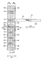
- FIG. 3 is a plan view showing a surface of the elastic seal member according to the embodiment of the present invention as viewed from the front side of the connector shown in FIG. 4 is an enlarged view of a range A1 in FIG. 3, and FIG. 5 is a cross-sectional view of the elastic seal member shown in FIG. 3, showing a V1-V1 cross section in FIG. 6 and 7 will be referred to later.
- the elastic seal member 12 is a member formed in a rectangular plate shape with an elastic material such as silicone rubber, and plays a role of preventing water from entering the connector housing 11.
- the elastic seal member 12 is inserted from the opening 112 of the connector housing 11.
- the elastic seal member 12 is provided with a plurality of seal insertion holes 121 through which the terminal-attached electric wires 14 are inserted in the insertion direction D11.
- the seal insertion hole 121 includes a small-size seal insertion hole 121S through which the small-sized terminal-attached electric wire 14 is inserted, and a large-size seal insertion hole 121L through which the large-sized electric wire with terminal 14 is inserted.
- seal insertion holes 121 The small-size seal insertion hole 121S and the large-size seal insertion hole 121L have the same configuration except for the size. Therefore, in the following description, these two types of seal-side insertion holes 121S and 121S will be simply referred to as seal insertion holes 121 unless otherwise specified.
- the inside of the seal insertion hole 121 has a structure shown in the cross-sectional view of FIG. In FIG. 5, only one of the terminal-attached electric wires 14 is representatively shown.
- the elastic seal member 12 is provided with a plurality of seal insertion holes 121. As shown in FIG. 5, a lip ring 121 a that protrudes over the entire circumference so as to be in close contact with the outer peripheral surface of the wire portion 142 of the terminal-attached electric wire 14 is inserted into the inner peripheral surface of each seal insertion hole 121. Four rows are arranged in the direction D11. When the terminal-attached electric wire 14 is inserted, the lip ring 121a comes into close contact with the outer peripheral surface of the electric wire portion 142, thereby preventing water from entering.
- each seal insertion hole 121 there are provided call-in portions 124 that form a wide opening that is recessed in a funnel shape and guides the insertion of the terminal-attached electric wire 14 into the seal insertion hole 121.
- the elastic seal member 12 is provided with a lightening groove 122 adjacent to the seal insertion hole 121 on both the front and back surfaces.
- the lightening groove 122 has a shape that does not overlap with the following circular range 121b in plan view when the surface on which the lightening groove 122 is provided is seen. Is formed.
- the circular range 121b is a circular range centered on the seal insertion hole 121, and is adjacent to the seal insertion hole 121 adjacent to each other across the lightening groove 122 (adjacent in the oblique direction in the example of FIG. 4). It has become.
- the lightening groove 122 positioned between the seal insertion holes 121 has at least a part of the outer edge thereof coincided with the outer periphery of the circular range 121b in plan view.
- the circular range 121b is a range having the following size.
- FIG. 6 is a schematic diagram showing the size of the circular range shown in FIG.
- FIG. 6A shows the size of the circular area 121b in a plan view similar to FIG.
- FIG. 6B shows a cross-sectional view of the seal insertion hole 121 for reference in FIG.
- the seal insertion hole 121 has a small diameter portion 121c having a small diameter ⁇ S corresponding to the inner diameter of the lip ring 121a, and a large diameter ⁇ L corresponding to the inner diameter of the valley portion between the lip rings 121a. And a large-diameter portion 121d having a wide hole.
- the two seal insertion holes 121 adjacent to each other without sandwiching the lightening groove 122 have a large distance 121d between them with a predetermined distance L1 between them.
- the circular area 121b described above is a circular area having a diameter ⁇ C obtained by adding two of the predetermined distance L1 that is the mutual distance between the large diameter portions 121d to the large diameter ⁇ L in the seal insertion hole 121. .
- a circular range 121b having a diameter ⁇ C obtained by adding two of the predetermined distances L1 to the large diameter ⁇ L of the seal insertion hole 121 is illustrated.
- the circular range referred to in the present invention is not limited to this, and may be, for example, a circular range having a slightly longer diameter than the above-described diameter ⁇ C.
- the lightening groove 122 is provided in a shape that does not overlap with the inlet portion 124 provided at the outlet of the seal insertion hole 121 in a plan view.
- the seal insertion holes 121 are arranged as follows in the above-described plan view. That is, the seal insertion holes 121 are arranged with a first interval d1 in the long side direction D4 (first direction) of the elastic seal member 12, and in the short side direction D5 (second direction) intersecting the long side direction D3. Are arranged with a second interval d2 wider than the first interval d1.
- the lightening groove 122 is provided adjacent to the seal insertion hole 121 in the short side direction D5.
- the lightening grooves 122 provided on both the front and back surfaces of the elastic seal member 12 correspond to two rows of the lip ring 121a at the central portion in the thickness direction D1 of the elastic seal member 12. It is formed with a depth d4 that leaves a surplus portion 123 having a thickness d3 to be formed.
- the terminal-attached electric wire 14 is inserted into the seal insertion hole 121 as follows. .
- FIG. 7 is a diagram schematically showing a state where the terminal-attached electric wire is inserted into the seal insertion hole of the elastic seal member shown in FIG.
- FIG. 7A shows a state in which the terminal 141 of the electric wire 14 with a terminal enters the inside while pushing the seal insertion hole 121 in the initial stage of insertion.
- FIG. 7B shows a state in which the terminal 141 passes through the seal insertion hole 121 and the electric wire portion 142 is located inside the seal insertion hole 121.
- the elastic seal member 12 of the present embodiment is provided with a lightening groove 122 adjacent to the seal insertion hole 121. For this reason, the pressure generated when passing through the terminal 141 is absorbed by contraction of the lightening groove 122 as shown in FIG. As a result, the insertion resistance when passing through the terminal 141 is suppressed.
- the pressure generated when the wire portion 142 is located inside the seal insertion hole 121 is also absorbed by the contraction of the lightening groove 122. For this reason, it is located next to the seal insertion hole 121 through which the terminal-attached electric wire 14 is inserted, and distortion of the seal insertion hole 121 through which the terminal-attached electric wire 14 is not inserted is suppressed.
- the insertion resistance is coupled with the fact that the pressure at the time of insertion is absorbed by the lightening groove 122 as described above. Will be suppressed.
- the seal insertion hole 122 is a circular range centering on the seal insertion hole 121, and is adjacent to the sandwiching groove 122. 121 are formed in a shape that does not overlap with a circular area 121b that does not overlap each other. As a result, a certain thickness is secured around the seal insertion hole 121, and a decrease in contact pressure between the inner surface of the seal insertion hole 121 and the terminal-attached electric wire 14 is suppressed, and a decrease in sealing performance is suppressed.
- the elastic seal member 12 of the present embodiment it is possible to suppress a decrease in the sealing performance while suppressing the insertion resistance to the seal insertion hole 121.
- the lightening groove 122 is provided in a shape that does not overlap with the inlet portion 124 provided at the outlet of the seal insertion hole 121.
- a thicker wall thickness is secured around the seal insertion hole 121, a decrease in the contact pressure between the inner surface of the seal insertion hole 121 and the terminal-attached electric wire 14 is further suppressed, and the sealing performance is reduced. It is further suppressed.
- the lightening groove 122 positioned between the seal insertion holes 121 is adjacent to at least a part of the outer edge with the lightening groove 122 in between in the plan view. It corresponds to the outer periphery of the circular range 121b corresponding to each of the matching seal insertion holes 121.
- the lightening groove 122 is formed to have a sufficient size in the plan view, and as a result, the insertion resistance to the seal insertion hole 121 is further increased. It will be suppressed.
- a lightening groove 122 is provided adjacent to the seal insertion hole 121 in the short side direction D5 having a relatively wide arrangement interval. Yes. That is, by providing the thinning groove 122 in a place with a sufficient margin, a certain thickness is secured around the seal insertion hole 121 in a wider range, and the deterioration of the sealing performance is further suppressed. be able to.
- the lip rings 121 a are provided in four rows on the inner peripheral surface of the seal insertion hole 121.
- the insertion resistance of the electric wire 14 with a terminal can be further suppressed by providing the lightening grooves 122 on both the front and back surfaces of the elastic seal member 12.
- the surplus part 123 equivalent to two rows of the lip ring 121a is left between the front and back side wall grooves 122, the inner surface of the inserted wire 14 with a terminal and the seal insertion hole 121 is inserted. As a result, the decrease in the sealing performance can be further suppressed.
- the circular range 121 b has the large diameter portion 121 d on the inner diameter (large diameter ⁇ L) of the large diameter portion 121 d of the seal insertion hole 121.
- This is a circular range having a diameter ⁇ C obtained by adding two the above-mentioned predetermined distances L1 that are mutually spaced.
- the lightening groove 122 is formed in a shape that does not overlap with the circular area 121b. For this reason, by adopting the circular range 121b having the above-described size, the circumference of the seal insertion hole 121, which tends to be thin, around the large-diameter portion 121d, including the direction of the thinning groove 122, is arranged around the entire circumference. A thickness corresponding to the predetermined distance L1 is ensured. Accordingly, a decrease in contact pressure between the inserted electric wire with terminal 14 and the inner surface of the seal insertion hole 121 can be suppressed, so that a decrease in sealing performance can be further suppressed.
- the seal insertion hole 121 (wire insertion hole) is provided in two large and small sizes so as to use two types of large and small electric wires 14 with terminals.
- the seal member 12 is illustrated.
- the elastic sealing member referred to in the present invention is not limited to this.
- the elastic sealing member referred to in the present invention may be, for example, a form in which only one type of electric wire with a terminal is used and a wire insertion hole corresponding to one size is provided, or three or more types of electric wires with a terminal are used.
- the form which provides three or more types of electric wire insertion holes corresponding to each size may be sufficient.
- the lip rings 121a arranged in four rows are illustrated as an example of the lip ring referred to in the present invention.
- the lip ring referred to in the present invention is not limited to this, and the number of lip rings referred to in the present invention may be any number such as 4 rows or 5 rows as long as it is 4 rows or more.
Landscapes
- Connector Housings Or Holding Contact Members (AREA)
Abstract
電線挿通孔への挿通抵抗を抑えつつも、シール性の低下を抑えることができる弾性シール部材及びコネクタを提供する。弾性シール部材(12)であって、端子付き電線が厚み方向(D1)に挿通されるシール挿通孔(121)(電線挿通孔)が複数配列されて設けられ、表裏面のうち少なくとも一方の面において、シール挿通孔(121)(電線挿通孔)に隣接して肉抜き溝(122)が設けられ、肉抜き溝(122)は、前記一方の面を見たときの平面視で、シール挿通孔(121)(電線挿通孔)を中心とした円形の範囲であって肉抜き溝(122)を挟んで隣り合うシール挿通孔(121)(電線挿通孔)同士では互いに重複しない円形範囲(121b)、と重ならない形状に形成されていることを特徴とする。
Description
本発明は、ワイヤハーネスの端末に設けられるコネクタに取り付けられる弾性シール部材と、そのような弾性シール部材を備えたコネクタに関するものである。
移動体としての自動車には、多種多様な電子機器が搭載されている。これらの電子機器は、互いの間で電力や制御信号などを伝えるためにワイヤハーネスによって接続されている。ワイヤハーネスは、複数の電線が束ねられた電線束と、この電線束の端末に取り付けられるコネクタとを備えている。このようなコネクタとしては、端子付き電線を複数収容するハウジングと、このハウジングの内部に設けられて外部からの水の浸入を防ぐ弾性シール部材とを備えたものが知られている(例えば、特許文献1参照。)。このような弾性シール部材としては、例えばシリコーンゴム等の弾性材料で板状に形成されてハウジングの開口に嵌め込まれるとともに、端子付き電線が挿通される電線挿通孔が設けられるものが多い。図8に、従来の弾性シール部材の一例を示す。
図8に示されている弾性シール部材510は、弾性材料で板状に形成されており、端子付き電線520が厚み方向に沿った挿通方向に挿通される電線挿通孔511が複数配列されて設けられている。
ここで、図8に示されている従来の弾性シール部材510では、電線挿通孔511に端子付き電線520が挿通されることで、その電線挿通孔511が拡径する。その結果、その拡径した電線挿通孔511の隣に位置する他の電線挿通孔511は歪む。そして、この歪みの程度が大き過ぎる場合には、その歪んだ電線挿通孔511への端子付き電線520の挿通抵抗が大きく挿通し難くなることがある。また、このような歪みを見越して電線挿通孔511を大きく形成したりすると、電線挿通孔511の内面と端子付き電線520との接触圧が低下してシール性が低下する恐れがある。
従って、本発明は、上記のような問題点に着目し、電線挿通孔への挿通抵抗を抑えつつも、シール性の低下を抑えることができる弾性シール部材及びコネクタを提供することを目的とする。
上記課題を解決するために、本発明の弾性シール部材は、弾性材料で板形状に形成され、筒形状のコネクタハウジングの一端側の開口に嵌入される弾性シール部材であって、端子付き電線が厚み方向に挿通される電線挿通孔が複数配列されて設けられ、前記板形状における表裏面のうち少なくとも一方の面において、前記電線挿通孔に隣接して肉抜き溝が設けられ、前記肉抜き溝は、前記一方の面を見たときの平面視で、前記電線挿通孔を中心とした円形の範囲であって前記肉抜き溝を挟んで隣り合う前記電線挿通孔同士では互いに重複しない円形範囲、と重ならない形状に形成されていることを特徴としている。
本発明の弾性シール部材によれば、電線挿通孔に端子付き電線が挿通されることで、その電線挿通孔が拡径したとしても、電線挿通孔に隣接して設けられた肉抜き溝が収縮することで、電線挿通済みの電線挿通孔の隣の電線挿通孔の歪みが抑えられる。これにより、電線挿通孔への挿通抵抗が抑えられる。このとき、肉抜き溝が、電線挿通孔を中心とした円形の範囲であって肉抜き溝を挟んで隣り合う前記電線挿通孔同士では互いに重複しない円形範囲、と重ならない形状に形成されている。これにより、電線挿通孔の周囲に一定の肉厚が確保されることとなり、電線挿通孔の内面と端子付き電線との接触圧の低下が抑えられてシール性の低下が抑えられる。このように、本発明の弾性シール部材によれば、電線挿通孔への挿通抵抗を抑えつつも、シール性の低下を抑えることができる。
また、本発明の弾性シール部材において、前記電線挿通孔の間に位置する前記肉抜き溝は、前記平面視で、その外縁の少なくとも一部が、当該肉抜き溝を挟んで隣り合う前記電線挿通孔それぞれに対応した前記円形範囲の外周と一致していることが好適である。
この好適な弾性シール部材によれば、上記のようにシール性の低下が抑えられるとともに、肉抜き溝が上記の平面視で十分な大きさに形成されることとなり、その結果、電線挿通孔への挿通抵抗が一層抑えられることとなる。
また、本発明の弾性シール部材において、複数の前記電線挿通孔は、前記平面視で、第1方向に第1間隔を開けて配列され、前記第1方向と交差する第2方向には前記第1間隔よりも広い第2間隔を開けて配列されており、前記肉抜き溝が、前記第2方向について前記電線挿通孔に隣接して設けられていることも好適である。
この好適な弾性シール部材によれば、肉抜き溝が、電線挿通孔の配列間隔が相対的に広い上記第2方向について電線挿通孔に隣接して設けられている。つまり、広さに余裕のある場所に肉抜き溝が設けられることで、電線挿通孔の周囲にはより広い範囲で一定の肉厚が確保されることとなり、シール性の低下を一層抑えることができる。
また、本発明の弾性シール部材において、前記電線挿通孔の内周面には、当該電線挿通孔に挿通された前記端子付き電線の電線部分の外周面に密接するように全周にわたり突出したリップ環が、前記厚み方向に4列以上に設けられており、前記肉抜き溝が、前記板形状における表裏面の双方に、当該板形状における厚み方向について相互間に、少なくとも前記リップ環の2列分に相当する余肉部分を残して形成されていることも好適である。
この好適な弾性シール部材によれば、弾性シール部材の表裏面の双方に肉抜き溝が設けられることで端子付き電線の挿通抵抗を一層抑えることができる。そして、表裏面の肉抜き溝の相互間に、リップ環の2列分に相当する余肉部分が残されていることで、挿通後の端子付き電線と電線挿通孔の内面との接触圧の低下が抑えられるので、シール性の低下を一層抑えることができる。
また、本発明の弾性シール部材において、前記電線挿通孔が、相対的に内径が小さい小径部と、相対的に内径が大きい大径部と、を有し、前記肉抜き溝を挟まずに隣り合う2つの前記電線挿通孔は、それぞれの前記大径部の相互間に所定距離が開くように設けられており、前記円形範囲が、前記大径部の内径に前記所定距離を2つ分加えた長さ以上の直径を有する円形の範囲であることも好適である。
この好適な弾性シール部材によれば、肉厚が薄くなりがちな上記の大径部の周囲に、肉抜き溝の方向も含めて、全周に亘って少なくとも上記の所定距離に相当する肉厚が確保されることとなる。その分、挿通後の端子付き電線と電線挿通孔の内面との接触圧の低下が抑えられるので、シール性の低下を一層抑えることができる。
上記課題を解決するために、本発明のコネクタは、筒形状のコネクタハウジングと、前記コネクタハウジングの一端側の開口に嵌入される弾性シール部材と、を備えたコネクタであって、前記弾性シール部材が、上述した本発明の弾性シール部材であることを特徴としている。
本発明のコネクタによれば、前記弾性シール部材が、上述した本発明の弾性シール部材であるので、電線挿通孔への挿通抵抗を抑えつつも、シール性の低下を抑えることができる。
本発明によれば、電線挿通孔への挿通抵抗を抑えつつも、シール性の低下を抑えることができる。
本発明の実施形態にかかる弾性シール部材を図1~図7を参照して説明する。
まず、本発明の一実施形態のコネクタの全体構成について説明する。図1は、本発明の一実施形態のコネクタを示す分解斜視図である。図2は、図1に示されている端子付き電線を示す図である。
図1に示されているコネクタ1は、嵌合レバー15の回動によって不図示の相手側コネクタとの嵌合を行うレバー嵌合式のコネクタである。このコネクタ1は、コネクタハウジング11と、弾性シール部材12と、リアグリッド13と、端子付き電線14と、嵌合レバー15と、端子位置保証(TPA)部材16と、パッキン17と、ダミー栓18と、を備えている。尚、ここでは、コネクタ1において図2に示されている端子付き電線14の電線部分142が延出する側をリア、その反対側で不図示の相手側コネクタが嵌合する側をフロントと呼ぶ。
コネクタハウジング11は、筒形状に形成され、その内部に、端子付き電線14の端子141が収容される端子収容室111が複数設けられている。
複数の端子収容室111それぞれには、端子付き電線14の端子141が1つずつ、図中に矢印で示されている弾性シール部材12の厚み方向D1に沿った挿通方向D11に挿通されて収容される。複数の端子収容室111の一部がフロント側に露出しており、これら複数の端子収容室111にTPA部材16が被せられる。
コネクタハウジング11のリア側は開口112となっており、この開口112から弾性シール部材12が挿通方向D11に嵌入され、その弾性シール部材12を端子収容室111側に押し込むように押圧しながらリアグリッド13が挿通方向D11に嵌入される。
また、コネクタハウジング11の外壁には、嵌合レバー15の回動軸113が突出して設けられている。
弾性シール部材12は、例えばシリコーンゴム等の弾性材料で板状に形成されて、上記のようにコネクタハウジング11の開口112に嵌入される。そして、端子付き電線14が弾性シール部材12の厚み方向D1に沿った挿通方向D11に挿通されるシール挿通孔121(電線挿通孔)が複数設けられている。各シール挿通孔121は、コネクタハウジング11の開口112に嵌入されたときに各端子収容室111に連通する。この弾性シール部材12については、後で詳細に説明する。
リアグリッド13は、上記のようにコネクタハウジング11の開口112に嵌入される。このリアグリッド13の外周面には、図1に示されているように係止爪131が設けられている。コネクタハウジング11の外壁に設けられた係止孔114にこの係止爪131が係止することで、弾性シール部材12を上記のように押圧した状態でリアグリッド13がコネクタハウジング11に固定される。リアグリッド13には、上記のシール挿通孔121に連通するグリッド挿通孔132が複数設けられている。
端子付き電線14は、図2に示されているように端子141と電線部分142とで構成される。尚、本実施形態では、コネクタハウジング11には、サイズの異なる2種類の端子付き電線が収容される。2種類の端子付き電線は、そのサイズを除いて互いに同等な構成を有している。そこで、以下では、2種類の端子付き電線について、特に断らない限りは区別せずに単に端子付き電線14と呼んで説明を行う。図1には、端子付き電線14が1本だけ代表的に示されている。端子付き電線14の端子141は、四角筒状のメス端子となっており、相手側コネクタのオス端子と接続される。この端子付き電線14は、挿通方向D11にグリッド挿通孔132及びシール挿通孔121に挿通され、端子141が端子収容室111に収容される。
嵌合レバー15は、コネクタハウジング11を図1中の上下方向に挟むように略C字状に形成された部材である。そして、上下2つの腕部151のそれぞれに、コネクタハウジング11の外壁から突出する回動軸113が嵌め込まれる軸受孔152が設けられている。図1に矢印D2で示されているように、この軸受孔152に回動軸113が嵌め込まれることで、コネクタハウジング11に嵌合レバー15が回動自在に固定される。また、各腕部151には、相手側コネクタに係止して本実施形態のコネクタ1へと引寄せる方向に案内する案内溝153が設けられている。2つの腕部151を繋ぐ部分が、作業者によって操作される操作部154となっている。案内溝153が相手側コネクタに係止した状態で、作業者が操作部154を操作して嵌合レバー15を回動させることで、相手側コネクタが本実施形態のコネクタ1へと引寄せられて両者が嵌合する。
コネクタハウジング11のフロント側には、パッキン17を間に挟んでTPA部材16が矢印D3方向に取り付けられる。
TPA部材16は、フロント側に露出した複数の端子収容室111に被せられるキャップ状の部材であり、各端子収容室111内で端子141が動かないように保持する役割を果たす。パッキン17は、TPA部材16とコネクタハウジング11との間隙を塞いで防水の役割を果たす部材である。このTPA部材16には、コネクタハウジング11の端子収容室111に連通し、相手側コネクタの端子が進入する端子進入孔161が複数設けられている。
ダミー栓18は、端子付き電線14が挿通されない不使用の端子収容室111に至るグリッド挿通孔132やシール挿通孔121を塞ぐ樹脂製のピンである。このダミー栓18により、これらのグリッド挿通孔132やシール挿通孔121からの水の浸入が防止される。このダミー栓18も、図示は省略されているが、大サイズと小サイズの2種類のものが設けられている。
次に、本発明の一実施形態である弾性シール部材12について図3~図7を参照して詳細に説明する。図3は、本発明の一実施形態である弾性シール部材を、図1に示されているコネクタのフロント側から見た面を示す平面図である。図4は、図3中の範囲A1の拡大図であり、図5は、図3に示されている弾性シール部材の、図3中のV1-V1断面を示す断面図である。図6及び図7については、後で参照する。
弾性シール部材12は、シリコーンゴム等の弾性材料で長方形の板形状に形成された部材であり、コネクタハウジング11内への水の浸入を防ぐ役割を果たす。この弾性シール部材12は、コネクタハウジング11の開口112から嵌入される。また、弾性シール部材12には、端子付き電線14が挿通方向D11に挿通するシール挿通孔121が複数配列されて設けられている。シール挿通孔121は、小サイズの端子付き電線14を挿通させる小サイズ用シール挿通孔121Sと、大サイズの端子付き電線14を挿通させる大サイズ用シール挿通孔121Lとからなる。尚、小サイズ用シール挿通孔121Sと大サイズ用シール挿通孔121Lは、そのサイズを除いて互いに同等な構成を有している。そこで、以下では、これら2種類のシール側挿通孔121S,121Sを、特に断らない限りは、単にシール挿通孔121と呼んで説明を行う。
本実施形態では、シール挿通孔121の内部が、図5の断面図に示された構造を有している。尚、図5には、端子付き電線14については1本のみが代表的に示されている。
弾性シール部材12にはシール挿通孔121が複数設けられている。そして、図5に示されているように、各シール挿通孔121の内周面には、端子付き電線14の電線部分142の外周面に密接するように全周にわたって突出したリップ環121aが挿通方向D11に4列配列されて設けられている。端子付き電線14が挿通されると、これらのリップ環121aが電線部分142の外周面に密接することで水の浸入が防がれる。また、各シール挿通孔121の両端の出口周辺には、漏斗状に凹んだ広口となって、端子付き電線14のシール挿通孔121への挿通を案内する呼込み部124が設けられている。
弾性シール部材12には、その表裏面の双方において、図3~図5のそれぞれに示されているように、シール挿通孔121に隣接して肉抜き溝122が設けられている。そして、この肉抜き溝122は、図4に示されているように、肉抜き溝122が設けられている面を見たときの平面視で、次のような円形範囲121bと重ならない形状に形成されている。円形範囲121bは、シール挿通孔121を中心とした円形の範囲であって肉抜き溝122を挟んで隣り合う(図4の例では斜め方向に隣り合う)シール挿通孔121同士では互いに重複しない範囲となっている。また、本実施形態では、シール挿通孔121の間に位置する肉抜き溝122は、平面視で、その外縁の少なくとも一部が、上記の円形範囲121bの外周と一致している。
また、本実施形態では、円形範囲121bが次のような大きさの範囲となっている。
図6は、図4に示されている円形範囲の大きさを示す模式図である。図6(A)には、図4と同様の平面図で円形範囲121bの大きさが示されている。また、図6(B)には、図6(A)で参照するためのシール挿通孔121の断面図が示されている。
図5を参照して説明したように、また、図6(B)にも示されているように、シール挿通孔121の内周面には、リップ環121aが挿通方向D11に4列配列されて設けられている。このため、シール挿通孔121は、リップ環121aの内径に相当する小径φSを有し孔が狭くなった小径部121cと、リップ環121aの相互間の谷部の内径に相当する大径φLを有し孔が広くなった大径部121dと、を有することとなっている。
そして、図6(A)に示されているように、肉抜き溝122を挟まずに隣り合う2つのシール挿通孔121は、それぞれの大径部121dが、相互間に所定距離L1を開けて隣り合っている。上述した円形範囲121bは、シール挿通孔121における上記の大径φLに、大径部121dの相互間隔である上記の所定距離L1を2つ分加えた直径φCを有する円形の範囲となっている。
尚、本実施形態では、本発明にいう円形範囲の一例として、シール挿通孔121の大径φLに上記の所定距離L1を2つ分加えた直径φCを有する円形範囲121bが例示されている。しかしながら、本発明にいう円形範囲は、これに限るものではなく、例えば上記の直径φCよりも若干長めの直径を有する円形の範囲等であってもよい。
ここで、図4に示さているように、肉抜き溝122は、平面視で、シール挿通孔121の出口に設けられた呼込み部124と重ならない形状に設けられている。
ここで、弾性シール部材12では、図3に示されているように、上記の平面視で、シール挿通孔121が、次のように配列されている。即ち、シール挿通孔121は、弾性シール部材12の長辺方向D4(第1方向)に第1間隔d1を開けて配列され、長辺方向D3と交差する短辺方向D5(第2方向)には第1間隔d1よりも広い第2間隔d2を開けて配列されている。そして、本実施形態では、肉抜き溝122が、短辺方向D5についてシール挿通孔121に隣接して設けられている。
さらに、本実施形態では、弾性シール部材12の表裏面の双方に設けられた肉抜き溝122は、弾性シール部材12における厚み方向D1の中央部に、上記のリップ環121aの2列分に相当する厚みd3の余肉部分123を残す深さd4で形成されている。
以上に説明した本実施形態の弾性シール部材12、及び、その弾性シール部材12を備えたコネクタ1によれば、端子付き電線14は、シール挿通孔121に次のように挿通されることとなる。
図7は、図3に示されている弾性シール部材のシール挿通孔に端子付き電線が挿通されるときの様子を模式的に示す図である。図7(a)には、挿通の初期で、端子付き電線14の端子141がシール挿通孔121を押し広げながら内部に進入する様子が示されている。図7(b)には、端子141がシール挿通孔121を通過し、シール挿通孔121の内部に電線部分142が位置している様子が示されている。
図7(a)に示されているように、端子付き電線14の端子141がシール挿通孔121に進入する際には、端子141によってシール挿通孔121が拡径される。その結果、挿通方向D11と交差するとともにシール挿通孔121の外側へと向かう矢印D6で示された圧力が生じる。
また、端子141の通過後には、図7(b)に示されているように、主に、リップ環121aを電線部分142に圧接させる矢印D7で示された圧力が生じる。また、このときは、端子141の通過時に比べるとその程度が小さいものの電線部分142によってシール挿通孔121が拡径される。その結果、図7(a)の矢印D6と同方向(即ち、矢印D7方向とは逆方向)の圧力が生じる。
ここで、本実施形態の弾性シール部材12には、シール挿通孔121に隣接して肉抜き溝122が設けられている。このため、端子141の通過時に生じる圧力は、図7(a)に示されているように肉抜き溝122が収縮することで吸収される。その結果、端子141の通過時の挿通抵抗が抑えられる。
同様に、シール挿通孔121の内部に電線部分142が位置している状態に生じる圧力も、肉抜き溝122が収縮することで吸収される。このため、端子付き電線14が挿通されたシール挿通孔121の隣に位置し、端子付き電線14が未挿通のシール挿通孔121の歪みが抑えられる。その結果、その未挿通のシール挿通孔121に端子付き電線14が挿通される際には、その挿通時の圧力が上記のように肉抜き溝122で吸収されることと相俟って挿通抵抗が抑えられることとなる。
このとき、本実施形態では、図4に示されているように、肉抜き溝122が、シール挿通孔121を中心とした円形の範囲であって肉抜き溝122を挟んで隣り合うシール挿通孔121同士では互いに重複しない円形範囲121b、と重ならない形状に形成されている。これにより、シール挿通孔121の周囲に一定の肉厚が確保されることとなり、シール挿通孔121の内面と端子付き電線14との接触圧の低下が抑えられてシール性の低下が抑えられる。このように、本実施形態の弾性シール部材12によれば、シール挿通孔121への挿通抵抗を抑えつつも、シール性の低下を抑えることができる。
また、本実施形態の弾性シール部材12では、肉抜き溝122は、シール挿通孔121の出口に設けられた呼込み部124と重ならない形状に設けられている。これにより、シール挿通孔121の周囲に一層厚みのある肉厚が確保されることとなり、シール挿通孔121の内面と端子付き電線14との接触圧の低下が一層抑えられてシール性の低下がさらに抑えられる。
また、本実施形態の弾性シール部材12では、シール挿通孔121の間に位置する肉抜き溝122は、上記の平面視で、その外縁の少なくとも一部が、その肉抜き溝122を挟んで隣り合うシール挿通孔121それぞれに対応した円形範囲121bの外周と一致している。これにより、上記のようにシール性の低下が抑えられるとともに、肉抜き溝122が上記の平面視で十分な大きさに形成されることとなり、その結果、シール挿通孔121への挿通抵抗が一層抑えられることとなる。
また、本実施形態の弾性シール部材12では、図3に示されているように、相対的に配列間隔が広い短辺方向D5についてシール挿通孔121に隣接して肉抜き溝122が設けられている。つまり、広さに余裕のある場所に肉抜き溝122が設けられることで、シール挿通孔121の周囲にはより広い範囲で一定の肉厚が確保されることとなり、シール性の低下を一層抑えることができる。
また、本実施形態の弾性シール部材12では、シール挿通孔121の内周面にはリップ環121aが4列に設けられている。これにより、弾性シール部材12の表裏面の双方に肉抜き溝122が設けられることで端子付き電線14の挿通抵抗を一層抑えることができる。そして、表裏面の肉抜き溝122の相互間に、リップ環121aの2列分に相当する余肉部分123が残されていることで、挿通後の端子付き電線14とシール挿通孔121の内面との接触圧が低下が抑えられるので、シール性の低下を一層抑えることができる。
また、本実施形態の弾性シール部材12では、図6を参照して説明したように、円形範囲121bは、シール挿通孔121の大径部121dの内径(大径φL)に、大径部121dの相互間隔である上記の所定距離L1を2つ分加えた直径φCを有する円形の範囲となっている。
上述したように、肉抜き溝122は、円形範囲121bと重ならない形状に形成されている。このため、上述した大きさの円形範囲121bを採用することで、肉厚が薄くなりがちなシール挿通孔121における大径部121dの周囲に、肉抜き溝122の方向も含めて、全周に亘って上記の所定距離L1に相当する肉厚が確保されることとなる。その分、挿通後の端子付き電線14とシール挿通孔121の内面との接触圧の低下が抑えられるので、シール性の低下を一層抑えることができる。
尚、前述した実施形態は本発明の代表的な形態を示したに過ぎず、本発明は、この実施形態に限定されるものではない。即ち、本発明の骨子を逸脱しない範囲で種々変形して実施することができる。かかる変形によってもなお本発明の弾性シール部材の構成を具備する限り、勿論、本発明の範疇に含まれるものである。
例えば、前述した実施形態では、本発明にいう弾性シール部材の一例として、大小2種類の端子付き電線14を用いるべく、シール挿通孔121(電線挿通孔)を、それぞれ大小2サイズ設ける形態の弾性シール部材12が例示されている。しかしながら、本発明にいう弾性シール部材はこれに限るものではない。本発明にいう弾性シール部材は、例えば、1種類の端子付き電線を用い、電線挿通孔を1サイズに対応したもののみ設ける形態であってもよく、あるいは、3種類以上の端子付き電線を用い、電線挿通孔を、各サイズに対応して3種類以上設ける形態であってもよい。
また、前述した実施形態では、本発明にいうリップ環の一例として、4列に配列されたリップ環121aが例示されている。しかしながら、本発明にいうリップ環はこれに限るものではなく、本発明にいうリップ環の数は4列以上であれば4列や5列等の任意の数であってもよい。
1 コネクタ
11 コネクタハウジング
12 弾性シール部材
14 端子付き電線
112 開口
121 シール挿通孔(電線挿通孔)
121a リップ環
121b 円形範囲
121c 小径部
121d 大径部
122 肉抜き溝
123 余肉部分
141 端子
142 電線部分
D1 厚み方向
D2,D3 矢印
D4 長辺方向(第1方向)
D5 短辺方向(第2方向)
d1 第1間隔
d2 第2間隔
L1 所定距離
φS 小径
φL 大径
φC 直径
11 コネクタハウジング
12 弾性シール部材
14 端子付き電線
112 開口
121 シール挿通孔(電線挿通孔)
121a リップ環
121b 円形範囲
121c 小径部
121d 大径部
122 肉抜き溝
123 余肉部分
141 端子
142 電線部分
D1 厚み方向
D2,D3 矢印
D4 長辺方向(第1方向)
D5 短辺方向(第2方向)
d1 第1間隔
d2 第2間隔
L1 所定距離
φS 小径
φL 大径
φC 直径
Claims (6)
- 弾性材料で板形状に形成され、筒形状のコネクタハウジングの一端側の開口に嵌入される弾性シール部材であって、
端子付き電線が厚み方向に挿通される電線挿通孔が複数配列されて設けられ、
前記板形状における表裏面のうち少なくとも一方の面において、前記電線挿通孔に隣接して肉抜き溝が設けられ、
前記肉抜き溝は、前記一方の面を見たときの平面視で、前記電線挿通孔を中心とした円形の範囲であって前記肉抜き溝を挟んで隣り合う前記電線挿通孔同士では互いに重複しない円形範囲、と重ならない形状に形成されていることを特徴とする弾性シール部材。 - 前記電線挿通孔の間に位置する前記肉抜き溝は、前記平面視で、その外縁の少なくとも一部が、当該肉抜き溝を挟んで隣り合う前記電線挿通孔それぞれに対応した前記円形範囲の外周と一致していることを特徴とする請求項1に記載の弾性シール部材。
- 複数の前記電線挿通孔は、前記平面視で、第1方向に第1間隔を開けて配列され、前記第1方向と交差する第2方向には前記第1間隔よりも広い第2間隔を開けて配列されており、
前記肉抜き溝が、前記第2方向について前記電線挿通孔に隣接して設けられていることを特徴とする請求項1又は2に記載の弾性シール部材。 - 前記電線挿通孔の内周面には、当該電線挿通孔に挿通された前記端子付き電線の電線部分の外周面に密接するように全周にわたり突出したリップ環が、前記厚み方向に4列以上に設けられており、
前記肉抜き溝が、前記板形状における表裏面の双方から形成され、当該板形状における厚み方向について相互間に、少なくとも前記リップ環の2列分に相当する余肉部分が残されていることを特徴とする請求項1~3のうち何れか一項に記載の弾性シール部材。 - 前記電線挿通孔が、相対的に内径が小さい小径部と、相対的に内径が大きい大径部と、を有し、
前記肉抜き溝を挟まずに隣り合う2つの前記電線挿通孔は、それぞれの前記大径部の相互間に所定距離が開くように設けられており、
前記円形範囲が、前記大径部の内径に前記所定距離を2つ分加えた長さ以上の直径を有する円形の範囲であることを特徴とする請求項1~4のうち何れか一項に記載の弾性シール部材。 - 筒形状のコネクタハウジングと、
前記コネクタハウジングの一端側の開口に嵌入される弾性シール部材と、
を備えたコネクタであって、
前記弾性シール部材が、請求項1~5のうち何れか一項に記載の弾性シール部材であることを特徴とするコネクタ。
Priority Applications (3)
| Application Number | Priority Date | Filing Date | Title |
|---|---|---|---|
| EP16870794.1A EP3386036B1 (en) | 2015-12-02 | 2016-12-01 | Elastic seal member and connector |
| CN201680064412.9A CN108352650B (zh) | 2015-12-02 | 2016-12-01 | 弹性密封部件和连接器 |
| US15/970,256 US10587071B2 (en) | 2015-12-02 | 2018-05-03 | Elastic seal member and connector |
Applications Claiming Priority (2)
| Application Number | Priority Date | Filing Date | Title |
|---|---|---|---|
| JP2015235811A JP6453747B2 (ja) | 2015-12-02 | 2015-12-02 | 弾性シール部材及びコネクタ |
| JP2015-235811 | 2015-12-02 |
Related Child Applications (1)
| Application Number | Title | Priority Date | Filing Date |
|---|---|---|---|
| US15/970,256 Continuation US10587071B2 (en) | 2015-12-02 | 2018-05-03 | Elastic seal member and connector |
Publications (1)
| Publication Number | Publication Date |
|---|---|
| WO2017094857A1 true WO2017094857A1 (ja) | 2017-06-08 |
Family
ID=58797498
Family Applications (1)
| Application Number | Title | Priority Date | Filing Date |
|---|---|---|---|
| PCT/JP2016/085790 Ceased WO2017094857A1 (ja) | 2015-12-02 | 2016-12-01 | 弾性シール部材及びコネクタ |
Country Status (5)
| Country | Link |
|---|---|
| US (1) | US10587071B2 (ja) |
| EP (1) | EP3386036B1 (ja) |
| JP (1) | JP6453747B2 (ja) |
| CN (1) | CN108352650B (ja) |
| WO (1) | WO2017094857A1 (ja) |
Families Citing this family (7)
| Publication number | Priority date | Publication date | Assignee | Title |
|---|---|---|---|---|
| JP6628095B2 (ja) * | 2016-06-22 | 2020-01-08 | 住友電装株式会社 | シール部材及び防水コネクタ |
| JP6768742B2 (ja) * | 2018-06-04 | 2020-10-14 | 矢崎総業株式会社 | 端子付き電線および端子付き電線の製造方法 |
| JP2019212458A (ja) * | 2018-06-04 | 2019-12-12 | 矢崎総業株式会社 | 端子付き電線および端子付き電線の製造方法 |
| JP7511127B2 (ja) | 2019-06-13 | 2024-07-05 | パナソニックIpマネジメント株式会社 | 封止部材およびそれを備える電子機器 |
| JP7543889B2 (ja) * | 2020-12-16 | 2024-09-03 | 株式会社オートネットワーク技術研究所 | コネクタ付き電線 |
| CN115143305B (zh) * | 2021-03-31 | 2023-12-26 | 浙江三花汽车零部件有限公司 | 流体控制组件及其制造方法 |
| JP7381520B2 (ja) * | 2021-06-11 | 2023-11-15 | 矢崎総業株式会社 | 不正接続検出装置 |
Citations (5)
| Publication number | Priority date | Publication date | Assignee | Title |
|---|---|---|---|---|
| JPH09180810A (ja) * | 1995-12-06 | 1997-07-11 | Whitaker Corp:The | 電気コネクタ用シール部材 |
| JP2006140019A (ja) * | 2004-11-11 | 2006-06-01 | Tyco Electronics Amp Kk | 防水コネクタおよびシール部材 |
| US7371115B1 (en) * | 2006-12-15 | 2008-05-13 | Delphi Technologies, Inc. | Mat seal device |
| JP2008166045A (ja) * | 2006-12-27 | 2008-07-17 | Sumitomo Wiring Syst Ltd | 防水コネクタ |
| JP2015032560A (ja) * | 2013-08-07 | 2015-02-16 | 株式会社オートネットワーク技術研究所 | フェライトコア内蔵防水コネクタ |
Family Cites Families (15)
| Publication number | Priority date | Publication date | Assignee | Title |
|---|---|---|---|---|
| EP0525171B1 (fr) * | 1991-02-15 | 1995-10-18 | Framatome Connectors Connectral | Connecteur electrique a passe-fils d'etancheite |
| JP3247048B2 (ja) * | 1996-08-28 | 2002-01-15 | 矢崎総業株式会社 | リップ付きゴム製品 |
| JP2000353567A (ja) * | 1999-06-10 | 2000-12-19 | Yazaki Corp | 防水コネクタ |
| JP2002141137A (ja) * | 2000-11-01 | 2002-05-17 | Sumitomo Wiring Syst Ltd | 防水コネクタ |
| JP2002270282A (ja) * | 2001-03-12 | 2002-09-20 | Yazaki Corp | 防水コネクタ及び防水コネクタの端子挿通方法 |
| JP2005317385A (ja) * | 2004-04-28 | 2005-11-10 | Tyco Electronics Amp Kk | 防水型コネクタ用シール部材及び防水型コネクタ |
| JP2006059595A (ja) * | 2004-08-18 | 2006-03-02 | Sumitomo Wiring Syst Ltd | 防水コネクタ |
| JP5035132B2 (ja) * | 2008-06-19 | 2012-09-26 | 住友電装株式会社 | 防水コネクタ |
| JP2010027231A (ja) | 2008-07-15 | 2010-02-04 | Yazaki Corp | 防水コネクタ |
| CN102576947A (zh) * | 2009-06-05 | 2012-07-11 | 安德鲁有限责任公司 | 夹持和夹紧同轴连接器 |
| JP2011086439A (ja) * | 2009-10-14 | 2011-04-28 | Yazaki Corp | シール構造 |
| JP5569297B2 (ja) * | 2010-09-24 | 2014-08-13 | 住友電装株式会社 | 防水コネクタ |
| JP2012221785A (ja) * | 2011-04-11 | 2012-11-12 | Sumitomo Wiring Syst Ltd | コネクタ |
| JP5931616B2 (ja) * | 2012-07-09 | 2016-06-08 | タイコエレクトロニクスジャパン合同会社 | 防水型コネクタ及びワイヤシール |
| JP6036663B2 (ja) * | 2013-11-26 | 2016-11-30 | 住友電装株式会社 | 防水コネクタ |
-
2015
- 2015-12-02 JP JP2015235811A patent/JP6453747B2/ja active Active
-
2016
- 2016-12-01 EP EP16870794.1A patent/EP3386036B1/en active Active
- 2016-12-01 CN CN201680064412.9A patent/CN108352650B/zh not_active Expired - Fee Related
- 2016-12-01 WO PCT/JP2016/085790 patent/WO2017094857A1/ja not_active Ceased
-
2018
- 2018-05-03 US US15/970,256 patent/US10587071B2/en active Active
Patent Citations (5)
| Publication number | Priority date | Publication date | Assignee | Title |
|---|---|---|---|---|
| JPH09180810A (ja) * | 1995-12-06 | 1997-07-11 | Whitaker Corp:The | 電気コネクタ用シール部材 |
| JP2006140019A (ja) * | 2004-11-11 | 2006-06-01 | Tyco Electronics Amp Kk | 防水コネクタおよびシール部材 |
| US7371115B1 (en) * | 2006-12-15 | 2008-05-13 | Delphi Technologies, Inc. | Mat seal device |
| JP2008166045A (ja) * | 2006-12-27 | 2008-07-17 | Sumitomo Wiring Syst Ltd | 防水コネクタ |
| JP2015032560A (ja) * | 2013-08-07 | 2015-02-16 | 株式会社オートネットワーク技術研究所 | フェライトコア内蔵防水コネクタ |
Also Published As
| Publication number | Publication date |
|---|---|
| JP2017103116A (ja) | 2017-06-08 |
| JP6453747B2 (ja) | 2019-01-16 |
| US10587071B2 (en) | 2020-03-10 |
| EP3386036B1 (en) | 2020-07-29 |
| CN108352650A (zh) | 2018-07-31 |
| EP3386036A1 (en) | 2018-10-10 |
| EP3386036A4 (en) | 2018-11-21 |
| CN108352650B (zh) | 2020-05-12 |
| US20180248303A1 (en) | 2018-08-30 |
Similar Documents
| Publication | Publication Date | Title |
|---|---|---|
| JP6453747B2 (ja) | 弾性シール部材及びコネクタ | |
| JP5631017B2 (ja) | コネクタ用のメス端子 | |
| US9553395B2 (en) | Connector having a barrel and an end bell | |
| CN112688109B (zh) | 嵌合连接器 | |
| JP2012199051A (ja) | シールドコネクタ | |
| WO2010027009A1 (ja) | コネクタ | |
| TWI635667B (zh) | 可提昇防水係數的高速信號傳輸連接器 | |
| JP2006140019A (ja) | 防水コネクタおよびシール部材 | |
| JP5486999B2 (ja) | コネクタ | |
| JP6431471B2 (ja) | 封止部材及びコネクタ | |
| JP2008192459A (ja) | 電気コネクタ | |
| JP6024611B2 (ja) | コネクタ | |
| JP2014053222A (ja) | 同軸コネクタ | |
| JP6727756B2 (ja) | コネクタ付きケーブルアセンブリ、及びコネクタアセンブリ | |
| JP6433723B2 (ja) | 中継コネクタ用防水カバー | |
| WO2015046321A1 (ja) | コネクタ | |
| JP4823844B2 (ja) | ソケット端子 | |
| JP6057304B2 (ja) | 弾性シール部材 | |
| JP6993393B2 (ja) | レバー式コネクタ | |
| JP2011228143A (ja) | コネクタ | |
| JP2016062813A (ja) | コネクタ | |
| JP2016062814A (ja) | コネクタ | |
| JPH09147967A (ja) | 防水構造 | |
| JP6983109B2 (ja) | コネクタ及びコネクタアセンブリ | |
| JP2017004877A (ja) | 弾性シール部材及びコネクタ |
Legal Events
| Date | Code | Title | Description |
|---|---|---|---|
| 121 | Ep: the epo has been informed by wipo that ep was designated in this application |
Ref document number: 16870794 Country of ref document: EP Kind code of ref document: A1 |
|
| NENP | Non-entry into the national phase |
Ref country code: DE |