WO2017104068A1 - 観察装置 - Google Patents
観察装置 Download PDFInfo
- Publication number
- WO2017104068A1 WO2017104068A1 PCT/JP2015/085479 JP2015085479W WO2017104068A1 WO 2017104068 A1 WO2017104068 A1 WO 2017104068A1 JP 2015085479 W JP2015085479 W JP 2015085479W WO 2017104068 A1 WO2017104068 A1 WO 2017104068A1
- Authority
- WO
- WIPO (PCT)
- Prior art keywords
- optical system
- light
- illumination
- sample
- emission area
- Prior art date
- Legal status (The legal status is an assumption and is not a legal conclusion. Google has not performed a legal analysis and makes no representation as to the accuracy of the status listed.)
- Ceased
Links
Images








Classifications
-
- G—PHYSICS
- G02—OPTICS
- G02B—OPTICAL ELEMENTS, SYSTEMS OR APPARATUS
- G02B21/00—Microscopes
- G02B21/06—Means for illuminating specimens
- G02B21/08—Condensers
- G02B21/088—Condensers for both incident illumination and transillumination
-
- G—PHYSICS
- G02—OPTICS
- G02B—OPTICAL ELEMENTS, SYSTEMS OR APPARATUS
- G02B21/00—Microscopes
- G02B21/06—Means for illuminating specimens
- G02B21/08—Condensers
- G02B21/14—Condensers affording illumination for phase-contrast observation
-
- G—PHYSICS
- G02—OPTICS
- G02B—OPTICAL ELEMENTS, SYSTEMS OR APPARATUS
- G02B21/00—Microscopes
- G02B21/24—Base structure
-
- G—PHYSICS
- G02—OPTICS
- G02B—OPTICAL ELEMENTS, SYSTEMS OR APPARATUS
- G02B21/00—Microscopes
- G02B21/02—Objectives
- G02B21/04—Objectives involving mirrors
Definitions
- the present invention relates to an observation device.
- an observation apparatus using a phase difference observation method or a differential interference observation method is known (see, for example, Patent Document 1).
- an object of the present invention is to provide an observation device capable of observing an object such as a cell without labeling without enlarging the device.
- an illumination optical system emits illumination light obliquely downward from below the sample, and illumination light emitted from the illumination optical system is reflected above the sample and transmitted through the sample
- An objective optical system for photographing transmitted light below the sample in a path different from that of the illumination optical system, the illumination optical system comprising a light source, and a mask for limiting light from the light source to a specific emission area
- collimating optical system for converting light limited by the mask into substantially parallel light, and when the emitting area is projected on a pupil plane of the objective optical system, a projection image of the emitting area is the pupil.
- the illumination optical system is disposed so as to partially overlap the edge portion of the observation device.
- the illumination light emitted from the light source is emitted obliquely upward from the lower side of the sample, and then reflected at the upper side of the sample to transmit the sample downward from the upper side.
- the transmitted light transmitted through the sample is photographed by an objective optical system of a path different from the illumination optical system disposed below the sample. Since both the light source unit and the objective optical system are disposed below the sample, it is possible to observe an object such as a cell without labeling by photographing the transmitted light without enlarging the apparatus.
- the light emitted from the light source is irradiated on the sample as illumination light whose emission area is limited by the mask, and after being collimated by the collimating optical system, it is reflected above the sample and is below the sample. It is incident near the pupil plane of the objective optical system. Since the illumination light that has become approximately parallel light by the collimating optical system is reflected above the sample, it is not necessary to change the angle of the transmitted light incident on the objective optical system even if the height of the reflection position changes. As a result, even if the height of the reflection position changes, it is not necessary to adjust the position of the light source, and the robustness of the observation device can be improved.
- conditional expression (1) may be satisfied.
- D is the pupil diameter of the objective optical system
- D is the beam diameter when the exit area is projected onto the pupil plane.
- conditional expression (2) may be satisfied.
- ds is the size of the emission area in the tilt direction of the illumination light emitted from the illumination optical system
- Fi is the focal length of the collimating optical system
- NAo is the numerical aperture on the sample side of the objective optical system is there.
- conditional expression (3) may be satisfied.
- ds is the size of the emission area in the tilt direction of the illumination light emitted from the illumination optical system
- Fi is the focal length of the collimating optical system
- NAo is the numerical aperture on the sample side of the objective optical system
- Fop is a focal length on the sample side from the pupil of the objective optical system
- ⁇ is an inclination angle of the illumination light converted into substantially parallel light by the collimating optical system at the position of the sample with respect to the optical axis of the objective optical system It is.
- the emission area may have a shape that constitutes a part of an annular zone.
- transmitted light enters the objective optical system from various directions, so the influence of vignette in the objective optical system can be suppressed, and the brightness unevenness of the image can be reduced while maintaining the contrast. it can.
- the mask may include a light reduction portion in the emission area where the transmittance decreases continuously or stepwise toward the radial direction. In this way, it is possible to configure illumination light that becomes bright toward the peripheral portion, and to compensate for the fact that the peripheral portion of the image is dark due to the effect of vignetting of the objective optical system.
- the mask may include a light reduction portion in the emission area, in which the transmittance increases continuously or stepwise in the radial inward direction.
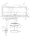
- the observation apparatus 1 is, as shown in FIG. 1, a stage 3 on which a container 2 containing a sample X such as cells is placed, and the stage 3 disposed below the stage 3.
- the objective optical system 5 is provided with an objective lens 5a for condensing the transmitted light, and is disposed outward in the radial direction of the objective optical system 5 for capturing the light transmitted through the sample X
- an illumination optical system 6 having a different path from the objective optical system 5 for emitting illumination light.
- the stage 3 includes a mounting table 3a made of an optically transparent material, for example, glass, so as to cover the upper side of the objective optical system 5 and the illumination optical system 6, and the container 2 is mounted on the upper surface of the mounting table 3a. It has become so.
- the container 2 is, for example, a cell culture flask having a top 2a, and is entirely made of an optically transparent resin.
- the illumination optical system 6 includes, as shown in FIG. 1, an LED light source (light source) 6a disposed outside the objective optical system 5, a diffusion plate 6b for diffusing light from the LED light source, and the diffusion plate 6b.
- An illumination mask (mask) 6 c provided to limit illumination light from the LED light source 6 a to a specific exit area, and a collimating lens (collimated optics to collimate the illumination light emitted from the restricted exit area and diffused gradually System) 6d.
- the illumination mask 6c has, as shown in FIG. 2, a circular opening 6e (emission area) for transmitting the illumination light in the light shielding member.
- the collimating lens 6 d is a light of the collimating lens 6 d so that the transmitted light reflected by the top plate 2 a of the container 2 and incident on the objective optical system 5 becomes oblique illumination with respect to the objective optical system 5.
- the axis A is shifted in the horizontal direction with respect to the central axis B of the illumination mask 6c.
- the pupil diameter of the aperture stop 5b provided on the pupil plane of the objective optical system 5 is D
- the lateral width of the luminous flux E in the direction of inclination of the illumination optical system 5 with respect to the optical axis C is satisfied. (1) 0.05 ⁇ d / D ⁇ 0.4
- ds is the size of the opening 6e of the illumination mask 6c in the direction in which the illumination light is emitted obliquely (diameter in the example shown in FIG. 2)
- Fop is the focal length on the sample X side from the pupil of the objective lens 5a.
- NAo is the numerical aperture on the sample X side of the objective lens 5a.
- part of the luminous flux of the illumination light projected onto the pupil plane of the objective optical system 5 is at the edge of the pupil of the objective optical system 5 (edge of the brightness stop). It is preferable that the The optimum condition is a position where the center of the transmitted light obliquely incident on the objective optical system 5 from the upper side coincides with the edge of the pupil. This condition is satisfied by satisfying the following conditional expression (3). (3) NAo-ds Fi / 2 Fop 2 ⁇ ⁇ NA NAo + ds Fi / 2 Fop 2
- the angle ⁇ is less than the lower limit of the conditional expression (3), the contrast of the image of the sample X becomes low and it becomes difficult to observe.
- the angle ⁇ exceeds the upper limit of the conditional expression (3), the image of the sample X becomes a dark field image, the field of view becomes dark, and it becomes difficult to clearly observe the contour of the sample X.
- the illumination light emitted from the LED light source 6a of the illumination optical system 6 passes upward through the illumination mask 6c and is emitted upward as a light flux limited to an emission area having a predetermined size, and is disposed upward
- the collimating lens 6 d By passing through the collimating lens 6 d, it is converted into substantially parallel light and becomes a light beam inclined toward the optical axis C of the objective optical system 5.
- the approximately parallel light directed obliquely upward from the collimator lens 6d passes through the mounting table 3a constituting the stage 3, the bottom surface of the container 2 and the liquid Y, is reflected by the top plate 2a of the container 2, and the sample obliquely downward It is the oblique illumination illuminated obliquely from above to X. Then, the transmitted light transmitted through the sample X is transmitted by the bottom surface of the container 2 and the mounting table 3a and then condensed by the objective lens 5a, imaged by the imaging lens 5c, and photographed by the imaging element 5d.
- the transmitted light which has transmitted the sample X is collected by the objective lens 5a.
- the transmitted light transmitted through the area where the sample X does not exist is not refracted and enters the objective lens 5a as substantially parallel light, so the edge of the brightness stop 5b disposed on the pupil plane of the objective lens 5a Image of the aperture 6e of the illumination mask 6c in a state in which a part of the light is projected, the transmitted light passing through the aperture stop 5b and the flare stop 5e is imaged by the imaging lens 5b and imaged by the imaging element 5d.
- the transmitted light transmitted through the region where the sample X is present is refracted by the difference in the refractive index of the sample X from the refractive index of the surroundings.
- light rays a and e which do not pass through the sample X and light rays c which are incident on the surface of the sample X at right angles pass through the inside of the edge of the aperture stop 5b without refraction, and thus form a bright image.
- the light ray b transmitted through the left end of the sample X in FIG. 4 is refracted and eclipsed by the edge of the aperture stop 5b. Further, the light ray d transmitted through the right end of the sample X in FIG. 4 is refracted and passes through a region closer to the center of the aperture stop 5b, and forms a bright image by the imaging lens 5c.
- the illumination light substantially collimated by the collimator lens 6d is emitted obliquely upward, so that as shown in FIG. 6, the containers having different heights of the top plate 2a Even when the stage 2 is placed on the stage 3, there is an advantage that the inclination angle of the illumination light incident on the objective optical system 5 does not need to be changed. That is, even if the height of the container 2 changes, the incident position of the light flux of the transmitted light on the pupil plane of the objective optical system 5 does not change, so that the light flux entering the pupil plane partially
- the arrangement as shown in 5b can be maintained, and the image of the contrasted sample X can be observed.
- the illumination mask 6c is exemplified to have a circular opening 6e, but instead, as shown in FIG. 7, a rectangular shape having a width ds in the inclination direction of the illumination light as shown in FIG. One having an opening 6e may be employed.
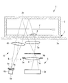
- the optical axis A of the collimator lens 6d is parallel to the optical axis C of the objective lens 5a, and the central axis B of the illumination mask 6c is shifted in the horizontal direction to obliquely upward from the collimator lens 6d. It is assumed that the illumination light emitted to the light source is inclined, but instead, the optical axis A of the collimator lens 6d is inclined with respect to the optical axis C of the objective optical system 5, as shown in FIGS. You may
- ⁇ is the inclination of the optical axis A of the collimator lens 6 d with respect to the optical axis C of the objective optical system 5.
- the illumination light passes near the optical axis A of the collimator lens 6d, so that less aberration is generated compared to the case of FIG. 1, and a good parallel luminous flux can be obtained over the entire luminous flux.
- a good parallel luminous flux can be obtained over the entire luminous flux.
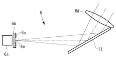
- the mirror 11 whose elevation angle is smaller than 45.degree.
- the prism 12 shown in FIG. 11 substantially parallel light emitted in the horizontal direction by the collimator lens 6d. It is possible to adopt a method of deflecting by As shown in FIG. 12, the mirror 11 or the prism 12 may be disposed between the LED light source 6a and the collimator lens 6d.
- an arc shape or a fan shape may be adopted as if a part of the annular zone is cut out.
- a part of the outside in the radial direction may be disposed so as to overlap the edge of the aperture stop 5b.
- the direction of the illumination light entering the objective optical system 5 is not limited to one direction, and the light is incident from various directions. There is an advantage that it is possible to reduce and suppress the occurrence of brightness unevenness of the image while maintaining the contrast.
- the light reduction area F having a transmittance gradient such that the transmittance becomes higher outward in the radial direction is provided in the emission area. You may decide to By doing this, it is possible to compensate for the peripheral portion of the image becoming dark due to the effect of vignetting of the objective optical system 5.
- the light reduction portion F having a transmittance gradient such that the transmittance decreases in the radial outward direction is provided in the emission area. It may be good. By doing this, the contrast of cells can be improved.
- observation device 5 objective optical system 6 illumination optical system 6a LED light source (light source) 6c illumination mask (mask) 6d Collimator lens (collimator optics) 6e opening (injection area) F Light reduction part X sample
Landscapes
- Physics & Mathematics (AREA)
- Chemical & Material Sciences (AREA)
- Analytical Chemistry (AREA)
- General Physics & Mathematics (AREA)
- Optics & Photonics (AREA)
- Microscoopes, Condenser (AREA)
- Optical Elements Other Than Lenses (AREA)
Abstract
Description
本発明は、上述した事情に鑑みてなされたものであって、装置を大型化させることなく、細胞等の被写体を標識せずに観察することができる観察装置を提供することを目的としている。
(1) 0.05≦d/D≦0.4
ここで、Dは前記対物光学系の瞳直径、Dは前記射出領域を前記瞳面に投影したときの光束直径である。
(2) 0.1≦ds/(NAo・Fi)≦0.8
ここで、dsは前記照明光学系から射出される照明光の傾斜方向の前記射出領域の大きさ、Fiは前記コリメート光学系の焦点距離、NAoは前記対物光学系の前記試料側の開口数である。
(3) NAo-ds・Fi/2Fop2≦θ≦NAo+ds・Fi/2Fop2
ここで、dsは前記照明光学系から射出される照明光の傾斜方向の前記射出領域の大きさ、Fiは前記コリメート光学系の焦点距離、NAoは前記対物光学系の前記試料側の開口数、Fopは前記対物光学系の瞳より前記試料側の焦点距離、θは前記コリメート光学系により略平行光に変換された照明光の、前記対物光学系の光軸に対する前記試料の位置での傾斜角度である。
このようにすることで、対物光学系に入射してくる透過光の光束の一部が対物光学系の瞳の辺縁にかかっており、試料の像にコントラストを与えることができる。
このようにすることで、対物光学系に対して、透過光が様々な方向から入り込むので、対物光学系におけるビネッティングの影響を抑え、コントラストを維持したまま像の明るさムラを低減することができる。
このようにすることで、周辺部に向かって明るくなる照明光を構成でき、対物光学系のビネッティングの影響で像の周辺部が暗くなるのを補償することができる。
このようにすることで、細胞のコントラストを向上することができる。
本実施形態に係る観察装置1は、図1に示されるように、細胞等の試料Xを収容した容器2を載置するステージ3と、該ステージ3の下方に配置され、ステージ3を上方から透過して来る光を集光する対物レンズ5aを備え、試料Xを透過した光を撮影する対物光学系5と、対物光学系5の径方向外方に配置され、ステージ3を透過して上方に照明光を射出する対物光学系5とは別経路の照明光学系6とを備えている。
容器2は、例えば、天板2aを有する細胞培養フラスコであり、全体的に光学的に透明な樹脂により構成されている。
コリメートレンズ6dは、容器2の天板2aによって反射されて対物光学系5に入射する透過光が、対物光学系5に対して傾斜することにより偏斜照明となるように、コリメートレンズ6dの光軸Aを照明マスク6cの中心軸Bに対して水平方向にシフトして配置されている。
θ=y/Fi
となる。
(1) 0.05≦d/D≦0.4
d=ds・Fop/Fi
D=2NA・Fop
これを変形することにより、条件式(2)を満足している。
(2) 0.1≦ds/(NAo・Fi)≦0.8
この条件は以下の条件式(3)を満足することにより満たされる。
(3) NAo-ds・Fi/2Fop2≦θ≦NAo+ds・Fi/2Fop2
照明光学系6のLED光源6aから発せられた照明光は照明マスク6cを通過することにより、所定の大きさを有する射出領域に制限された光束として上方に向けて射出され、上方に配されているコリメートレンズ6dを通過することによって略平行光に変換されるとともに、対物光学系5の光軸Cに向かって傾斜する光束となる。
図4において、試料Xを通過しない光線a,eおよび試料Xの表面に直交して入射する光線cは屈折することなく明るさ絞り5bの辺縁の内側を通過するので、明るい像を結ぶ。
さらに、図4において試料Xの右端を透過した光線dは、屈折させられて明るさ絞り5bのより中心に近い領域を通過させられ、結像レンズ5cによって明るい像を結ぶ。
この場合、以下の条件式が成立する。
θ=α+y/Fi
ここで、αは対物光学系5の光軸Cに対するコリメートレンズ6dの光軸Aの傾きである。
5 対物光学系
6 照明光学系
6a LED光源(光源)
6c 照明マスク(マスク)
6d コリメートレンズ(コリメート光学系)
6e 開口(射出領域)
F 減光部
X 試料
Claims (7)
- 試料の下方から斜め上方に向けて照明光を射出する照明光学系と、
該照明光学系から射出された照明光が前記試料の上方で反射されて前記試料を透過した透過光を前記試料の下方において前記照明光学系とは別経路で撮影する対物光学系とを備え、
前記照明光学系が、光源と、該光源からの光を特定の射出領域に制限するマスクと、該マスクにより制限された光を略平行光にするコリメート光学系とを備え、
前記射出領域が、前記対物光学系の瞳面に投影されたときに、前記射出領域の投影像が、前記瞳の辺縁部に部分的に重なるように前記照明光学系が配置されている観察装置。 - 条件式(1)を満足する請求項1に記載の観察装置。
(1) 0.05≦d/D≦0.4
ここで、Dは前記対物光学系の瞳直径、Dは前記射出領域を前記瞳面に投影したときの光束直径である。 - 条件式(2)を満足する請求項1に記載の観察装置。
(2) 0.1≦ds/(NAo・Fi)≦0.8
ここで、dsは前記照明光学系から射出される照明光の傾斜方向の前記射出領域の大きさ、Fiは前記コリメート光学系の焦点距離、NAoは前記対物光学系の前記試料側の開口数である。 - 条件式(3)を満足する請求項1に記載の観察装置。
(3) NAo-ds・Fi/2Fop2≦θ≦NAo+ds・Fi/2Fop2
ここで、dsは前記照明光学系から射出される照明光の傾斜方向の前記射出領域の大きさ、Fiは前記コリメート光学系の焦点距離、NAoは前記対物光学系の前記試料側の開口数、Fopは前記対物光学系の瞳より前記試料側の焦点距離、θは前記コリメート光学系により略平行光に変換された照明光の、前記対物光学系の光軸に対する前記試料の位置での傾斜角度である。 - 前記射出領域が、輪帯の一部を構成する形状である請求項1から請求項4のいずれかに記載の観察装置。
- 前記マスクが、前記射出領域内に、径方向内方に向かって透過率が連続的または段階的に低くなる減光部を備える請求項5に記載の観察装置。
- 前記マスクが、前記射出領域内に、径方向内方に向かって透過率が連続的または段階的に高くなる減光部を備える請求項5に記載の観察装置。
Priority Applications (5)
| Application Number | Priority Date | Filing Date | Title |
|---|---|---|---|
| CN201580085163.7A CN108369330B (zh) | 2015-12-18 | 2015-12-18 | 观察装置 |
| PCT/JP2015/085479 WO2017104068A1 (ja) | 2015-12-18 | 2015-12-18 | 観察装置 |
| DE112015007195.4T DE112015007195T5 (de) | 2015-12-18 | 2015-12-18 | Beobachtungsvorrichtung |
| JP2017556292A JP6633650B2 (ja) | 2015-12-18 | 2015-12-18 | 観察装置 |
| US15/984,949 US10877256B2 (en) | 2015-12-18 | 2018-05-21 | Observation device |
Applications Claiming Priority (1)
| Application Number | Priority Date | Filing Date | Title |
|---|---|---|---|
| PCT/JP2015/085479 WO2017104068A1 (ja) | 2015-12-18 | 2015-12-18 | 観察装置 |
Related Child Applications (1)
| Application Number | Title | Priority Date | Filing Date |
|---|---|---|---|
| US15/984,949 Continuation US10877256B2 (en) | 2015-12-18 | 2018-05-21 | Observation device |
Publications (1)
| Publication Number | Publication Date |
|---|---|
| WO2017104068A1 true WO2017104068A1 (ja) | 2017-06-22 |
Family
ID=59056199
Family Applications (1)
| Application Number | Title | Priority Date | Filing Date |
|---|---|---|---|
| PCT/JP2015/085479 Ceased WO2017104068A1 (ja) | 2015-12-18 | 2015-12-18 | 観察装置 |
Country Status (5)
| Country | Link |
|---|---|
| US (1) | US10877256B2 (ja) |
| JP (1) | JP6633650B2 (ja) |
| CN (1) | CN108369330B (ja) |
| DE (1) | DE112015007195T5 (ja) |
| WO (1) | WO2017104068A1 (ja) |
Cited By (10)
| Publication number | Priority date | Publication date | Assignee | Title |
|---|---|---|---|---|
| CN107315240A (zh) * | 2017-07-28 | 2017-11-03 | 黄朝旭 | 一种便携式显微装置 |
| CN110133826A (zh) * | 2018-02-08 | 2019-08-16 | 奥林巴斯株式会社 | 信息取得装置 |
| EP3521892A4 (en) * | 2016-09-29 | 2020-07-29 | Olympus Corporation | OBSERVATION DEVICE |
| CN112384606A (zh) * | 2018-07-06 | 2021-02-19 | 北海道公立大学法人札幌医科大学 | 观察装置 |
| US11016279B2 (en) | 2016-07-11 | 2021-05-25 | Olympus Corporation | Observation device |
| US11150456B2 (en) | 2016-09-06 | 2021-10-19 | Olympus Corporation | Observation apparatus |
| US11163143B2 (en) | 2016-09-06 | 2021-11-02 | Olympus Corporation | Observation apparatus |
| JP2022509823A (ja) * | 2018-11-30 | 2022-01-24 | コーニング インコーポレイテッド | 細胞培養監視のための小型光学結像システム |
| JP2022023771A (ja) * | 2020-07-27 | 2022-02-08 | オリンパス株式会社 | 観察装置、光偏向ユニット、像形成方法 |
| WO2025239347A1 (ja) * | 2024-05-16 | 2025-11-20 | 株式会社ニコン | 顕微鏡装置 |
Families Citing this family (7)
| Publication number | Priority date | Publication date | Assignee | Title |
|---|---|---|---|---|
| WO2017098657A1 (ja) * | 2015-12-11 | 2017-06-15 | オリンパス株式会社 | 観察装置 |
| WO2018062215A1 (ja) | 2016-09-30 | 2018-04-05 | オリンパス株式会社 | 観察装置 |
| CN109791275B (zh) | 2016-09-30 | 2022-05-27 | 奥林巴斯株式会社 | 观察装置 |
| WO2018220670A1 (ja) | 2017-05-29 | 2018-12-06 | オリンパス株式会社 | 観察装置 |
| JP7193989B2 (ja) * | 2018-11-19 | 2022-12-21 | 株式会社エビデント | 顕微鏡装置 |
| JP2022189083A (ja) * | 2021-06-10 | 2022-12-22 | 株式会社エビデント | 観察装置、リフレクター、及び、位相物体の観察方法 |
| FR3167450A1 (fr) * | 2024-10-15 | 2026-04-17 | Treefrog Therapeutics | Système d’analyse de microcompartiments cellulaires ou de tissus cellulaires |
Citations (4)
| Publication number | Priority date | Publication date | Assignee | Title |
|---|---|---|---|---|
| JPS57178212A (en) * | 1981-04-27 | 1982-11-02 | Nippon Kogaku Kk <Nikon> | Microscope optical system |
| JP2001166219A (ja) * | 1999-12-07 | 2001-06-22 | Fine Opt Kk | 皮膚観察装置 |
| JP2004318185A (ja) * | 2004-08-20 | 2004-11-11 | Olympus Corp | 光制御部材を有する光学顕微鏡 |
| JP2011008188A (ja) * | 2009-06-29 | 2011-01-13 | Olympus Corp | 光学顕微鏡 |
Family Cites Families (45)
| Publication number | Priority date | Publication date | Assignee | Title |
|---|---|---|---|---|
| DE3906555A1 (de) | 1989-03-02 | 1989-07-06 | Zeiss Carl Fa | Auflicht-objektbeleuchtungseinrichtung |
| JPH02232614A (ja) | 1989-03-06 | 1990-09-14 | Res Dev Corp Of Japan | 暗視野顕微鏡の照明方法とその装置 |
| US5751475A (en) | 1993-12-17 | 1998-05-12 | Olympus Optical Co., Ltd. | Phase contrast microscope |
| JPH07261089A (ja) | 1994-03-24 | 1995-10-13 | Olympus Optical Co Ltd | 位相差顕微鏡 |
| JP3699761B2 (ja) | 1995-12-26 | 2005-09-28 | オリンパス株式会社 | 落射蛍光顕微鏡 |
| DE69836030T2 (de) | 1997-08-29 | 2007-01-11 | Olympus Optical Co., Ltd. | Mikroskop |
| DE10017823B4 (de) | 2000-04-10 | 2004-08-26 | Till I.D. Gmbh | Mikroskopische Beleuchtungsvorrichtung |
| JP4535645B2 (ja) | 2001-07-06 | 2010-09-01 | 株式会社 ジャパン・ティッシュ・エンジニアリング | 接着細胞選別装置、細胞増殖能評価装置、それらのプログラム及びそれらの方法 |
| JP4370554B2 (ja) | 2002-06-14 | 2009-11-25 | 株式会社ニコン | オートフォーカス装置およびオートフォーカス付き顕微鏡 |
| JP4453088B2 (ja) | 2002-06-14 | 2010-04-21 | 株式会社ニコン | オートフォーカス装置及び顕微鏡 |
| JP4434649B2 (ja) | 2003-03-27 | 2010-03-17 | 株式会社Eci | 観察器具及びそれを用いた観察方法 |
| US20070177255A1 (en) | 2003-03-27 | 2007-08-02 | Shiro Kanegasaki | Observing tool and observing method using the same |
| JP4411866B2 (ja) | 2003-06-02 | 2010-02-10 | 株式会社ニコン | 顕微鏡装置 |
| JP4329423B2 (ja) | 2003-06-17 | 2009-09-09 | 株式会社ニコン | 顕微鏡装置 |
| EP1630586B1 (en) | 2003-06-02 | 2015-01-07 | Nikon Corporation | Microscope device |
| US7799559B2 (en) | 2003-10-24 | 2010-09-21 | Olympus Corporation | Culture microscope apparatus |
| JP4740554B2 (ja) | 2004-05-12 | 2011-08-03 | オリンパス株式会社 | 培養顕微鏡装置 |
| JP2005331623A (ja) | 2004-05-18 | 2005-12-02 | Ccs Inc | 顕微鏡用照明装置 |
| JP4731847B2 (ja) | 2004-07-15 | 2011-07-27 | オリンパス株式会社 | ペトリディッシュ、チャンバー装置、光学顕微鏡観察方法及び試料分析方法 |
| JP4652801B2 (ja) * | 2004-12-22 | 2011-03-16 | オリンパス株式会社 | 透過照明装置、それを備えた顕微鏡、及び透過照明方法 |
| JP4393986B2 (ja) | 2004-12-24 | 2010-01-06 | シーシーエス株式会社 | 光照射装置 |
| WO2006101056A1 (ja) | 2005-03-22 | 2006-09-28 | Medinet Co., Ltd. | 細胞培養評価システム、細胞培養評価方法および細胞培養評価プログラム |
| JP2007264410A (ja) | 2006-03-29 | 2007-10-11 | Nidec Copal Corp | 肌観察装置 |
| JP5039355B2 (ja) | 2006-10-13 | 2012-10-03 | 株式会社カネカ | 自動培養装置 |
| KR100813915B1 (ko) | 2006-10-31 | 2008-03-18 | 전자부품연구원 | 세포 배양 관찰 장치 |
| JP2008209726A (ja) | 2007-02-27 | 2008-09-11 | Olympus Corp | 照明装置 |
| US7952705B2 (en) * | 2007-08-24 | 2011-05-31 | Dynamic Throughput Inc. | Integrated microfluidic optical device for sub-micro liter liquid sample microspectroscopy |
| JP2009217222A (ja) | 2008-03-06 | 2009-09-24 | Takashi Goto | 反射型透過照明補助装置付観察台 |
| EP2312367A1 (en) | 2009-10-16 | 2011-04-20 | Olympus Corporation | Laser scanning microscope |
| JP2011141444A (ja) | 2010-01-07 | 2011-07-21 | Nikon Corp | 顕微鏡システム |
| US8873027B2 (en) | 2010-04-23 | 2014-10-28 | Hamamatsu Photonics K.K. | Cell observation device and cell observation method |
| CN103210338A (zh) | 2010-08-30 | 2013-07-17 | 三洋电机株式会社 | 观察装置、观察程序及观察系统 |
| WO2013047315A1 (ja) | 2011-09-30 | 2013-04-04 | 三洋電機株式会社 | ビームスプリッタおよび観察装置 |
| WO2013094434A1 (ja) | 2011-12-22 | 2013-06-27 | 三洋電機株式会社 | 観察システム、観察システムの制御方法及びプログラム |
| JP5985883B2 (ja) | 2012-05-17 | 2016-09-06 | オリンパス株式会社 | 顕微鏡 |
| KR101384843B1 (ko) | 2012-09-07 | 2014-05-07 | 주식회사 나노엔텍 | 현미경 및 그 제어방법 |
| WO2014041820A1 (ja) | 2012-09-13 | 2014-03-20 | 京セラオプテック株式会社 | 顕微鏡 |
| EP2993509B1 (en) * | 2013-04-30 | 2019-06-26 | Olympus Corporation | Sample observation device and sample observation method |
| TWI486625B (zh) * | 2013-05-16 | 2015-06-01 | Univ Nat Central | 數位全像顯微鏡 |
| JP6211389B2 (ja) | 2013-10-25 | 2017-10-11 | 株式会社キーエンス | 顕微鏡装置 |
| JP6066110B2 (ja) | 2014-06-11 | 2017-01-25 | 横河電機株式会社 | 細胞吸引支援システム |
| JP6297210B2 (ja) | 2015-03-31 | 2018-03-20 | オリンパス株式会社 | 観察装置 |
| KR20170078810A (ko) | 2015-03-31 | 2017-07-07 | 올림푸스 가부시키가이샤 | 관찰 장치 및 관찰 방법 |
| WO2017098657A1 (ja) | 2015-12-11 | 2017-06-15 | オリンパス株式会社 | 観察装置 |
| WO2018220670A1 (ja) | 2017-05-29 | 2018-12-06 | オリンパス株式会社 | 観察装置 |
-
2015
- 2015-12-18 WO PCT/JP2015/085479 patent/WO2017104068A1/ja not_active Ceased
- 2015-12-18 JP JP2017556292A patent/JP6633650B2/ja active Active
- 2015-12-18 CN CN201580085163.7A patent/CN108369330B/zh active Active
- 2015-12-18 DE DE112015007195.4T patent/DE112015007195T5/de not_active Withdrawn
-
2018
- 2018-05-21 US US15/984,949 patent/US10877256B2/en active Active
Patent Citations (4)
| Publication number | Priority date | Publication date | Assignee | Title |
|---|---|---|---|---|
| JPS57178212A (en) * | 1981-04-27 | 1982-11-02 | Nippon Kogaku Kk <Nikon> | Microscope optical system |
| JP2001166219A (ja) * | 1999-12-07 | 2001-06-22 | Fine Opt Kk | 皮膚観察装置 |
| JP2004318185A (ja) * | 2004-08-20 | 2004-11-11 | Olympus Corp | 光制御部材を有する光学顕微鏡 |
| JP2011008188A (ja) * | 2009-06-29 | 2011-01-13 | Olympus Corp | 光学顕微鏡 |
Cited By (17)
| Publication number | Priority date | Publication date | Assignee | Title |
|---|---|---|---|---|
| US11016279B2 (en) | 2016-07-11 | 2021-05-25 | Olympus Corporation | Observation device |
| US11150456B2 (en) | 2016-09-06 | 2021-10-19 | Olympus Corporation | Observation apparatus |
| US11163143B2 (en) | 2016-09-06 | 2021-11-02 | Olympus Corporation | Observation apparatus |
| EP3521892A4 (en) * | 2016-09-29 | 2020-07-29 | Olympus Corporation | OBSERVATION DEVICE |
| CN107315240B (zh) * | 2017-07-28 | 2024-04-26 | 佛山市好客电子科技有限公司 | 一种便携式显微装置 |
| CN107315240A (zh) * | 2017-07-28 | 2017-11-03 | 黄朝旭 | 一种便携式显微装置 |
| CN110133826B (zh) * | 2018-02-08 | 2022-04-01 | 奥林巴斯株式会社 | 信息取得装置 |
| CN110133826A (zh) * | 2018-02-08 | 2019-08-16 | 奥林巴斯株式会社 | 信息取得装置 |
| JP2019139025A (ja) * | 2018-02-08 | 2019-08-22 | オリンパス株式会社 | 情報取得装置 |
| CN112384606B (zh) * | 2018-07-06 | 2024-04-12 | 北海道公立大学法人札幌医科大学 | 观察装置 |
| CN112384606A (zh) * | 2018-07-06 | 2021-02-19 | 北海道公立大学法人札幌医科大学 | 观察装置 |
| US12110480B2 (en) | 2018-07-06 | 2024-10-08 | Nipro Corporation | Observation device |
| US11921102B2 (en) | 2018-11-30 | 2024-03-05 | Corning Incorporated | Compact optical imaging system for cell culture monitoring |
| JP2022509823A (ja) * | 2018-11-30 | 2022-01-24 | コーニング インコーポレイテッド | 細胞培養監視のための小型光学結像システム |
| JP2022023771A (ja) * | 2020-07-27 | 2022-02-08 | オリンパス株式会社 | 観察装置、光偏向ユニット、像形成方法 |
| JP7605667B2 (ja) | 2020-07-27 | 2024-12-24 | 株式会社エビデント | 観察装置、光偏向ユニット、像形成方法 |
| WO2025239347A1 (ja) * | 2024-05-16 | 2025-11-20 | 株式会社ニコン | 顕微鏡装置 |
Also Published As
| Publication number | Publication date |
|---|---|
| JPWO2017104068A1 (ja) | 2018-10-04 |
| CN108369330A (zh) | 2018-08-03 |
| CN108369330B (zh) | 2020-11-06 |
| US10877256B2 (en) | 2020-12-29 |
| DE112015007195T5 (de) | 2018-08-30 |
| US20180267285A1 (en) | 2018-09-20 |
| JP6633650B2 (ja) | 2020-01-22 |
Similar Documents
| Publication | Publication Date | Title |
|---|---|---|
| US10877256B2 (en) | Observation device | |
| JP6619025B2 (ja) | 観察装置 | |
| JP6658351B2 (ja) | 画像表示装置およびヘッドアップディスプレイシステム | |
| US11150456B2 (en) | Observation apparatus | |
| JP2003322822A (ja) | 画像表示装置 | |
| JP6911112B2 (ja) | 観察装置 | |
| US11163143B2 (en) | Observation apparatus | |
| EP2977809A1 (en) | Illumination optical element, illumination optical system, and illumination apparatus | |
| WO2015098242A1 (ja) | 標本観察装置および標本観察方法 | |
| JP6975553B2 (ja) | コリメートレンズ、光照射装置および車両用灯具。 | |
| JP6619026B2 (ja) | 観察装置 | |
| US8988518B2 (en) | Medical imaging system | |
| US20190137749A1 (en) | Observation device | |
| CN114070971B (zh) | 观察装置、光偏转单元、像形成方法 | |
| WO2018051514A1 (ja) | 観察装置 | |
| JP2013250378A (ja) | 照明光学系及びプロジェクタ装置 | |
| JP2014074801A (ja) | 光整形器、照明光学系および撮像装置 | |
| JP2011013589A (ja) | 照明光学系及び照明装置 | |
| JP2018084602A (ja) | 顕微鏡用の落射照明光学系、及び、顕微鏡 | |
| JP2010250182A (ja) | 輪帯光源装置、顕微鏡 |
Legal Events
| Date | Code | Title | Description |
|---|---|---|---|
| 121 | Ep: the epo has been informed by wipo that ep was designated in this application |
Ref document number: 15910758 Country of ref document: EP Kind code of ref document: A1 |
|
| ENP | Entry into the national phase |
Ref document number: 2017556292 Country of ref document: JP Kind code of ref document: A |
|
| WWE | Wipo information: entry into national phase |
Ref document number: 112015007195 Country of ref document: DE |
|
| 122 | Ep: pct application non-entry in european phase |
Ref document number: 15910758 Country of ref document: EP Kind code of ref document: A1 |