WO2017104131A1 - Dispositif de transport de pièce à travailler et procédé pour transporter une pièce à travailler dans lequel ce dernier est utilisé - Google Patents
Dispositif de transport de pièce à travailler et procédé pour transporter une pièce à travailler dans lequel ce dernier est utilisé Download PDFInfo
- Publication number
- WO2017104131A1 WO2017104131A1 PCT/JP2016/005119 JP2016005119W WO2017104131A1 WO 2017104131 A1 WO2017104131 A1 WO 2017104131A1 JP 2016005119 W JP2016005119 W JP 2016005119W WO 2017104131 A1 WO2017104131 A1 WO 2017104131A1
- Authority
- WO
- WIPO (PCT)
- Prior art keywords
- workpiece
- support
- suction cup
- idle
- conveyor
- Prior art date
- Legal status (The legal status is an assumption and is not a legal conclusion. Google has not performed a legal analysis and makes no representation as to the accuracy of the status listed.)
- Ceased
Links
Images




Classifications
-
- B—PERFORMING OPERATIONS; TRANSPORTING
- B21—MECHANICAL METAL-WORKING WITHOUT ESSENTIALLY REMOVING MATERIAL; PUNCHING METAL
- B21D—WORKING OR PROCESSING OF SHEET METAL OR METAL TUBES, RODS OR PROFILES WITHOUT ESSENTIALLY REMOVING MATERIAL; PUNCHING METAL
- B21D43/00—Feeding, positioning or storing devices combined with, or arranged in, or specially adapted for use in connection with, apparatus for working or processing sheet metal, metal tubes or metal profiles; Associations therewith of cutting devices
-
- B—PERFORMING OPERATIONS; TRANSPORTING
- B65—CONVEYING; PACKING; STORING; HANDLING THIN OR FILAMENTARY MATERIAL
- B65H—HANDLING THIN OR FILAMENTARY MATERIAL, e.g. SHEETS, WEBS, CABLES
- B65H3/00—Separating articles from piles
- B65H3/08—Separating articles from piles using pneumatic force
-
- B—PERFORMING OPERATIONS; TRANSPORTING
- B65—CONVEYING; PACKING; STORING; HANDLING THIN OR FILAMENTARY MATERIAL
- B65H—HANDLING THIN OR FILAMENTARY MATERIAL, e.g. SHEETS, WEBS, CABLES
- B65H5/00—Feeding articles separated from piles; Feeding articles to machines
- B65H5/08—Feeding articles separated from piles; Feeding articles to machines by grippers, e.g. suction grippers
- B65H5/10—Reciprocating or oscillating grippers, e.g. suction or gripper tables
Definitions
- the present invention relates to a workpiece transfer device and a workpiece transfer method using the workpiece transfer device, and more particularly to a workpiece transfer device for transferring workpieces one by one from a stack to the downstream side and a workpiece transfer method using the same.
- a workpiece as a raw material is generally carried in as a so-called stack in which a plurality of sheets are stacked.
- the workpieces are taken out from the stack one by one and transported downstream.
- a pallet transport apparatus for transporting a pallet loaded with sheet stacks to a destack position
- a destack feeder including a magnet floater installed at a stack position and a vacuum lifter that sucks and transfers a sheet material separated by the magnet floater to a magnet conveyor
- the uppermost workpiece of the stack is conveyed in the vertical direction by the vacuum lifter, and the workpiece is conveyed in the horizontal direction by the magnetic conveyor.
- non-magnetic workpieces such as aluminum plates and FRP plates have attracted attention as substitutes for magnetic workpieces (hereinafter referred to as “magnetic workpieces”) such as iron plates and steel plates. Since non-magnetic workpieces are generally lighter than magnetic workpieces, there are advantages in that material costs are low and energy costs required for conveyance can be reduced.
- an apparatus that replaces the magnet conveyor has been developed.
- an endless annular belt that is wound between a pair of pulleys and transported and moved in a predetermined transport direction, an adsorption surface that is formed on the outer peripheral surface of the belt to adsorb a workpiece, and an inner peripheral portion of the belt.
- a vacuum conveyor having an intake chamber communicated with an intake device is known (for example, see Patent Document 2). In the vacuum conveyor, since the work is attracted to the outer peripheral surface of the belt and transported, the non-magnetic work can be transported in the horizontal direction.
- a workpiece transfer apparatus provided with a feeder having a gripper.
- the top non-magnetic workpiece in the stack is attracted and lifted by a vacuum cup, the non-magnetic workpiece is gripped by a gripper attached to the feeder, and the feeder is slid horizontally in that state. By doing so, it is possible to transport the non-magnetic work.
- the present invention has been made in view of the above circumstances, and can carry a deformed workpiece regardless of the presence or absence of magnetism, and can prevent deformation of the workpiece during conveyance.
- An object is to provide a transport device.
- the present inventor has intensively studied to solve the above-mentioned problems.As a result, a plurality of fixed suction cup portions are provided on the lower surface of the base portion and the support rod via the support portions, and the movable suction cup portion of the stacker device is provided on the upper surface. As a result, it has been found that the above problem can be solved by arranging the support rods so that they can be moved up and down between the support rods, and the present invention has been completed.
- the present invention is (1) a workpiece transfer device for transferring a workpiece from a stack in which a plurality of workpieces are stacked, a conveyor having an endless belt, a base attached to the lower surface of the endless belt, A first support portion attached to the lower surface, a plurality of support rods provided so as to be continuous from the upstream end of the base portion toward the upstream side, and attached to the lower surface of each of the support rods A second support portion, a plurality of fixed suction cup portions respectively provided on the lower surfaces of the first support portion and the second support portion, an idle portion provided below the first support portion, and a second support portion
- a stacker device having a movable suction cup portion provided above and movable up and down; and an arrangement portion provided below the second support portion and in which a stack is arranged.
- the endless belt is arranged so as to be able to move up and down between the heels, and the endless belt is second from the first position where the first support part is above the idle part and from the second position where the second support part is above the idle part. It exists in the workpiece transfer device that can reciprocate to the position.
- This invention exists in the workpiece conveyance apparatus as described in said (1) or (2) further equipped with (3) DB bucket for collect
- each of the first support portion and the second support portion is provided with two or more rows of fixed suction cup portions in a direction perpendicular to the transport direction, and the interval between the fixed suction cup portions is
- the workpiece conveying apparatus according to any one of the above (1) to (3), which is 100 mm or less.
- the present invention resides in (5) the workpiece transfer apparatus according to any one of (1) to (4), wherein the workpiece is a non-magnetic workpiece.
- the first support portion is attached to the lower surface of the base portion at two locations along the longitudinal direction of the base portion, and an idle portion is provided below each of the first support portions.
- the workpiece transfer device according to any one of (1) to (5) above is provided.
- the present invention is (7) a method for transferring a workpiece using the workpiece transfer device according to any one of (1) to (5), wherein a first step of arranging a stack in an arrangement section, At one position, the moving suction cup portion is moved downward to be attracted to the first workpiece, and then the moving suction cup portion is moved upward to lift the first workpiece, and the first workpiece is moved to the second support portion.
- the second step for adsorbing to the fixed suction cup unit, and the conveyor is driven from the first position to the second position. At the second position, the second support unit removes the first workpiece and places it on the idle unit.
- the third step to be placed, and the conveyor is driven so that the second position is changed to the first position.
- the moving suction cup portion is moved downward to be attracted to the second workpiece, and then the moving suction is performed. Move up the cup The second workpiece is lifted, and the second workpiece is attracted to the fixed suction cup portion of the second support portion. At the same time, the first workpiece placed on the idle portion is fixed to the fixed suction cup portion of the first support portion.
- the second support section removes the second workpiece and places it on the idle section.
- a fifth step in which the first support part detaches the first workpiece, and after performing the first step, the second step, and the third step, the workpiece in which the fourth step and the fifth step are alternately repeated. Exist in the transport method.
- the movable suction cup portion sucks the uppermost workpiece of the stack in which a plurality of workpieces are stacked and moves up and down.
- the workpiece can be conveyed in the vertical direction.
- the moving suction cup portion is disposed between the support rods in a top view, the up and down movement of the moving suction cup portion is not hindered by the support rod.
- the workpiece can be delivered to the fixed suction cup portion provided on the second support portion on the lower surface of the support rod. And a workpiece
- the idle part is provided below the first support part on the lower surface of the base part, the work adsorbed by the fixed suction cup part of the second support part is removed at the second position. Once placed in the idle section. And in the 1st position, the fixed suction cup part of the 1st support part attracts the work, and the lower endless belt moves to the downstream side, so that the work can be further conveyed in the horizontal direction.
- a workpiece conveyance apparatus in an idle part, it can confirm the presence or absence of generation
- the moving suction cup portion and the fixed suction cup portion are used, even if the workpiece is irregularly shaped, the workpiece can be sucked and transferred regardless of the presence or absence of magnetism. Further, since the moving suction cup portion and the fixed suction cup portion are used, deformation of the workpiece being conveyed can be suppressed. As a result, the outer edge of the workpiece can be used as a product, so that a cutting process is not required and the yield is improved.
- the apparatus when the apparatus further includes a conveyance conveyor that is disposed below the front end on the downstream side of the conveyor so as to overlap the front end in the vertical direction and extends downstream from the front end of the conveyor,
- the workpiece conveyed by the conveyor via the support portion or the like can be easily dropped onto the upper surface of the conveyor. And it becomes possible to convey a workpiece
- the DB bucket when the DB bucket is further provided below the idle portion, even if a defective workpiece such as a so-called double blank is placed on the idle portion, by dropping the defective workpiece onto the DB bucket. Can be removed and recovered.
- each of the first support portion and the second support portion is provided with two or more rows of fixed suction cup portions in a direction perpendicular to the transfer direction, and between the fixed suction cup portions.
- the interval is 100 mm or less, even if the workpiece is deformed, it can be surely adsorbed.
- the interval between the fixed suction cup portions is sufficiently narrow, deformation of the work hardly occurs.
- the workpiece conveyance device of the present invention even if the workpiece is a non-magnetic workpiece, it can be reliably conveyed.
- the first support part is attached to the lower surface of the base part at two locations along the longitudinal direction of the base part, and the idle part is provided below each of the first support parts. In this case, since the presence or absence of a double blank can be confirmed at two idle parts, a conveyance trouble due to the double blank can be further avoided.
- the workpiece transfer method of the present invention includes a first step, a second step, a third step, a fourth step, and a fifth step, and after performing the first step, the second step, and the third step, the fourth step
- the workpiece can be reliably conveyed even if it is a deformed workpiece regardless of the presence or absence of magnetism. Further, deformation of the workpiece being conveyed can be suppressed.
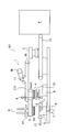
- FIG. 1 is a side view schematically showing a first embodiment of a workpiece transfer apparatus according to the present invention.
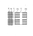
- FIG. 2 is a bottom view for explaining an arrangement state of the fixed suction cup portion with respect to the first support portion and the second support portion in the work transfer device according to the first embodiment.
- FIG. 3 is a flowchart showing a workpiece transfer method according to the first embodiment.
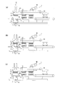
- FIGS. 4A to 4C are explanatory views for explaining the first step and the second step of the workpiece transfer method according to the first embodiment.
- FIG. 5A and FIG. 5B are explanatory diagrams for explaining a third step of the workpiece transfer method according to the first embodiment.
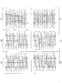
- FIGS. 10 (a) to 10 (f) are schematic views showing an example in which the fixed suction cup unit sucks and holds an irregularly shaped workpiece in the workpiece transfer apparatus according to another embodiment.
- the workpiece conveyance device is a device for taking out one sheet at a time from a workpiece positioned at the top of a stack in which a plurality of workpieces are stacked, and conveying them one by one.
- the workpiece can be processed one by one with a press machine or the like.
- magnetic works such as an iron plate and a steel plate
- nonmagnetic works such as an aluminum plate and a FRP board
- FIG. 1 is a side view schematically showing a first embodiment of a workpiece transfer apparatus according to the present invention.
- the workpiece transfer device 100 according to the first embodiment includes a conveyor 1 having an endless belt 10, a base 2 attached to the lower surface of the lower endless belt 10, and a lower surface of the base 2.
- a first support portion 21 attached at two locations, a plurality of support rods 3 provided so as to continue from the upstream end of the base portion 2 toward the upstream side, and the support rod 3
- the second support portion 31 attached to each lower surface, the plurality of fixed suction cup portions 4 respectively provided on the lower surfaces of the first support portion 21 and the second support portion 31, and the two first support portions 21 respectively.
- a stacker device 6 provided below the second support portion 31 and a stacker device 6 having a movable suction cup portion 61 provided above the second support portion 31 and movable up and down. S is It includes a placement unit A is location, the. Note that the base 2, the first support portion 21, the second support portion 31, the support rod 3, and the fixed suction cup portion 4 are configured to reciprocate integrally with the endless belt 10. On the other hand, the idle unit 5, the stacker device 6, and the arrangement unit A are fixed.
- the moving suction cup unit 61 is used for transferring the workpiece in the vertical direction
- the fixed suction cup unit 4 is used for transferring in the horizontal direction. Even if the workpiece is irregular, the workpiece can be sucked and conveyed. In addition, since no gripper is used, deformation of the workpiece during conveyance can be suppressed.
- the conveyor 1 includes a pair of rollers and an endless belt 10 installed on the pair of rollers.
- a rotating shaft 11 is attached to a part of the endless belt 10, and the endless belt 10 moves in the horizontal direction by rotating the rotating shaft 11.
- a servo motor M is used to drive the rotating shaft 11. Thereby, the moving direction and moving distance of the endless belt 10 can be controlled. Specifically, the servo motor M causes the lower endless belt 10 to move from the first position where the first support portion 21 (first upstream support portion 21a) is above the idle portion 5 (upstream idle portion 5a). The second support portion 31 can reciprocate to a second position above the idle portion 5 (upstream idle portion 5a). Details of the reciprocating movement will be described later. Incidentally, FIG. 1 shows a state where the conveyor 1 is in the first position.
- the base 2 is fixed to the lower surface of the lower endless belt 10 as described above. Therefore, the base 2 is reciprocated in the horizontal direction integrally with the endless belt 10.
- the first support portion 21 is attached to the lower surface of the base 2 at two locations along the longitudinal direction (transfer direction) of the base 2.
- each 1st support part 21 since each 1st support part 21 is being fixed to the base 2, each 1st support part 21 will also reciprocate in a horizontal direction with the base 2 and the endless belt 10.
- the first support portion 21 on the upstream side is referred to as a “first upstream support portion 21 a” for convenience.
- the first support portion 21 on the downstream side is referred to as “first downstream support portion 21b” for convenience.
- Both the first upstream support portion 21a and the first downstream support portion 21b have the same shape, and a large number of fixed suction cup portions 4 are provided on the lower surfaces thereof. Details and arrangement of the fixed suction cup portion 4 will be described later.
- the shape of the workpiece is not rectangular.
- the fixed suction cup portion 4 can hold and hold any flat portion of the workpiece, even in a circular shape or a triangular shape, or a holed workpiece in which a hole is formed in the workpiece. it can.
- each second support portion 31 is fixed to the corresponding support rod 3, and each support rod 3 is fixed to the base portion 2. Therefore, each second support portion 31 is also the base portion 2. And, it will reciprocate in the horizontal direction together with the endless belt 10.
- FIG. 2 is a bottom view for explaining an arrangement state of the fixed suction cup portion with respect to the first support portion and the second support portion in the work transfer device according to the first embodiment.
- a plurality of first upstream support portions 21 a are arranged so as to be equidistant from each other in the direction (width direction) perpendicular to the transfer direction with respect to the lower surface of the base 2.
- a plurality of first downstream support portions 21b are arranged on the lower surface of the base portion 2 so as to be equidistant from each other in a direction (width direction) perpendicular to the transport direction.
- the support rods 3 are juxtaposed on the base 2 so that a plurality of support rods 3 are equidistant from each other in a direction (width direction) perpendicular to the transport direction, and the second support portion 31 is provided on the lower surface of each support rod 3. Are attached to each.
- the interval between the adjacent first upstream support portions 21a, the interval between the adjacent first downstream support portions 21b, and the interval between the adjacent second support portions 31 Match. That is, each of the first upstream support portion 21a, the first downstream support portion 21b, and the second support portion 31 is arranged in a square lattice shape. Thereby, when the 1st downstream support part 21b and the 2nd support part 31 adsorb
- the number of each of the first upstream support portion 21a, the first downstream support portion 21b, and the second support portion 31 arranged in the direction (width direction) perpendicular to the transfer direction is at least two or more. Yes, and preferably 3 or more. Thereby, even if the workpiece is irregularly shaped, it is possible to reliably hold it by suction.
- the fixed suction cup portions 4 provided on the lower surfaces of the first upstream support portion 21a, the first downstream support portion 21b, and the second support portion 31 are all the same, and commercially available ones can be used as appropriate.
- the fixed suction cup portion 4 can be elastically deformed in the vertical direction because the cup at the tip is made of an elastic member. For this reason, even if the workpiece has a three-dimensional shape, if the undulation in the height direction is relatively small, it can be adsorbed.
- the fixed suction cup portions 4 are arranged in three rows in a direction (width direction) perpendicular to the transport direction, and a staggered lattice Are arranged in a shape.
- interval of each fixed suction cup part is 100 mm or less, and it is more preferable that it is 40 mm or less.
- the support rod 3 and the second support portion 31 are arranged in parallel so that a plurality of support rods 3 and the second support portion 31 are equally spaced from each other in a direction (width direction) perpendicular to the transfer direction.
- a moving suction cup portion 61 which will be described later, is disposed between the adjacent support rods 3 when viewed from above. For this reason, the up-and-down movement of the moving suction cup portion 61 is not hindered by the support rod 3.
- the stacker device 6 has a moving suction cup portion 61 and is disposed above the support rod 3. As described above, the moving suction cup 61 passes between the support rods 3 and can be moved up and down.
- the moving suction cup portion 61 has the same structure as the above-described fixed suction cup portion 4 except that it can be moved up and down.
- the placement unit A includes a lift 7. That is, in the placement portion A, the stack S is placed on the lift 7. For this reason, in the workpiece transfer apparatus 100, the stack S can be lifted up by the lift 7. Thereby, since stack S itself can be raised, the raising / lowering moving distance of the movable suction cup part 61 of the stacker apparatus 6 can be made small.
- the lift-up by the lift 7 may be a pitch feed that rises every time one workpiece is conveyed, or may rise a certain distance after several workpieces are conveyed.
- a pair of magnet floaters 71 are provided so as to be positioned on both sides of the stack S when the stack S is placed. Thereby, for example, when the stack S is a laminated body of magnetic workpieces, the magnet floater 71 applies a magnetic force to the stack S, whereby the uppermost magnetic workpiece can be easily peeled off from the magnetic workpiece below. .
- the idle part 5 is provided below the first upstream support part 21a and below the first downstream support part 21b, respectively.
- the upstream idle portion 5 is referred to as an “upstream idle portion 5a” for convenience, and the downstream idle portion 5 is used. Is referred to as “downstream idle part 5b” for convenience.
- Both the upstream idle part 5a and the downstream idle part 5b have a lift. For this reason, the upstream idle part 5a and the downstream idle part 5b can lift and move the workpiece placed on the upper surface thereof. As a result, the work comes into contact with the fixed suction cup portion 4 and is sucked and held.
- the workpiece adsorbed by the fixed suction cup portion 4 of the second support portion 31 is once arranged in the upstream idle portion 5a at the second position, and then, at the first position, the fixed suction cup portion 4 of the first support portion 21a. As the lower endless belt 10 moves, it is further conveyed downstream. Details of the conveyance will be described later.
- the laser displacement sensor 9 is attached to the upstream idle part 5a. Therefore, in the workpiece conveyance device 100, when the second support unit 31 conveys the workpiece in the horizontal direction and reaches the upper portion of the upstream idle unit 5a, the laser displacement sensor 9 causes the workpieces to come into close contact with each other to move the workpiece 2 It is detected whether or not a defective work such as a so-called double blank is generated. Thereby, it can prevent that a workpiece
- the DB bucket 8 is arrange
- the transfer conveyor 15 is disposed below the front end on the downstream side of the conveyor 1 so as to overlap the front end in the vertical direction.
- the transport conveyor 15 extends downstream from the downstream end of the conveyor 1, and after dropping the work transported by the conveyor 1 via the first support portion 21 or the like onto the upper surface of the transport conveyor 15,
- the workpieces can be transported one by one downstream.
- the position of the workpiece can be adjusted by the centering device C installed on the transport conveyor 15, and further press processing can be performed by the press machine P installed downstream of the transport conveyor 15.
- FIG. 3 is a flowchart showing a workpiece transfer method according to the first embodiment.
- the workpiece transfer method according to the first embodiment includes a first step S1, a second step S2, a third step S3, a fourth step S4, and a fifth step S. . Then, after performing the first step S1, the second step S2, and the third step S3, the fourth step S4 and the fifth step S are repeatedly performed alternately.
- the workpiece can be reliably conveyed even if it is a deformed workpiece regardless of the presence or absence of magnetism. Further, deformation of the workpiece being conveyed can be suppressed.
- the first step S1 is a step of placing the stack S on the lift 7 of the placement unit A.
- positioning to the lift 7 is not specifically limited.
- the magnet floaters 71 are installed on both sides of the stack S. When the stack S is a stack of nonmagnetic workpieces, the magnet floater 71 is not necessary.
- FIGS. 4A to 4C are explanatory views for explaining the first step and the second step of the workpiece transfer method according to the first embodiment.
- the moving suction cup portion 61 of the stacker device 6 is moved downward at the first position.
- the moving suction cup portion 61 passes between the support rods 3.
- the moving suction cup unit 61 is brought into contact with the stack S and is attracted to the uppermost first work W1 of the stack S.
- the moving suction cup portion 61 is lifted while the first work W1 is sucked and held, whereby the first work W1 is lifted, and the first work W1 is moved to the second position as shown in FIG. 4C.
- the fixed suction cup unit 4 sucks and holds the first workpiece.
- FIG. 5A and FIG. 5B are explanatory diagrams for explaining a third step of the workpiece transfer method according to the first embodiment.
- the servo motor M of the workpiece transfer device 100 drives the endless belt 10 of the conveyor 1 to move horizontally from the first position to the second position shown in FIG.
- the laser displacement sensor 9 detects the thickness of the first workpiece W1, thereby determining whether or not it is a double blank.
- the second support part 31 detaches the first work W1, and the first work W1 is placed on the upstream idle part 5a. Placed.
- it is determined that it is a double blank after being placed on the upstream idle unit 5a, it is dropped into the DB bucket 8 via a chute (not shown) and collected.
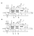
- FIG. 6A and FIG. 6B are explanatory diagrams for explaining a fourth step of the workpiece transfer method according to the first embodiment.
- the servo motor M of the workpiece transfer device 100 drives the endless belt 10 of the conveyor 1 to move horizontally from the second position to the first position shown in FIG. Then, at the first position, the moving suction cup portion 61 of the stacker device 6 is moved downward. Then, as shown in FIG. 6A, the moving suction cup unit 61 is brought into contact with the stack S and is attracted to the uppermost second work W ⁇ b> 2 of the stack S.
- the moving suction cup portion 61 is lifted while the second workpiece W2 is sucked and held, whereby the second workpiece W2 is lifted, and the second workpiece W2 is moved to the second position as shown in FIG. 6B.
- the fixed suction cup portion 4 of the second support portion 31 holds the second workpiece W2 by suction.
- the lift moves the first work W1 upward and contacts the fixed suction cup portion 4 of the first upstream support portion 21a.
- the fixed suction cup portion 4 of the first upstream support portion 21a sucks and holds the first workpiece W1.
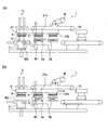
- FIG. 7A and FIG. 7B are explanatory diagrams for explaining the fifth step of the workpiece transfer method according to the first embodiment.
- the servo motor M of the workpiece transfer device 100 drives the endless belt 10 of the conveyor 1 to move horizontally from the first position to the second position shown in FIG.
- the second support part 31 detaches the second work W2
- the second work W2 is placed on the upstream idle part 5a
- the first upstream support The part 21a detaches the first work W1, and the first work W1 is placed on the downstream idle part 5b.
- the 1st upstream support part 21a removes
- the 1st work W1 is mounted on the conveyance conveyor 15. Will be placed.
- the endless belt 10 of the conveyor 1 is horizontally moved to the first position, and the moving suction cup portion 61 of the stacker device 6 is attracted to the third work at the first position.
- the third workpiece W3 is transferred to the fixed suction cup portion 4 of the second support portion 31.
- the lift causes the second workpiece W2 to move upward, thereby attracting the lift to the fixed suction cup portion 4 of the first upstream support portion 21a, and similarly, the first workpiece W1. Is moved up and adsorbed to the fixed suction cup portion 4 of the first downstream support portion 21b.
- the endless belt 10 of the conveyor 1 is horizontally moved to the second position, and at the second position, the second support portion 31 removes and attaches the third work W3, and the third work Is placed on the upstream idle portion 5a, the first upstream support portion 21a is detached from the second workpiece W2, the second workpiece W2 is placed on the downstream idle portion 5b, and the first downstream support portion 21b is placed on the first workpiece W1.
- the first workpiece W1 is placed on the transport conveyor (see FIG. 8).
- the workpiece conveyed by the conveyor is subjected to position adjustment by the centering device C and press processing by the press machine P on the downstream side.
- the fourth step S4 and the fifth step S5 are repeated, so that the workpiece is removed from the state of the stack S. It can be sequentially conveyed one by one.
- FIG. 9 is a side view schematically showing a second embodiment of the workpiece transfer apparatus according to the present invention.
- the workpiece transfer device 101 according to the second embodiment includes a conveyor 1 having an endless belt 10, a base 2 attached to the lower surface of the lower endless belt 10, and a lower surface of the base 2.
- the attached first support portion 211 a plurality of support rods 3 provided so as to be continuous with the base portion 2 from the upstream end of the base portion 2 toward the upstream side, and the lower surfaces of the respective support rods 3
- a second support portion 31 attached to the first support portion 211, a plurality of fixed suction cup portions 4 provided on the lower surface of the first support portion 211, an idle portion 51 provided below the first support portion 21, and a second support
- the stacker device 6 is provided above the portion 31 and has a movable suction cup portion 61 that can be moved up and down, and the placement portion A that is provided below the second support portion 31 and in which the stack S is disposed.
- the first support portion 211 is attached to only one place on the lower surface of the base portion 2, and the idle portion 51 is also one below the first support portion 211. Except for being provided only at the place, it is the same as the workpiece transfer apparatus 100 according to the first embodiment.
- FIG. 9 shows a state where the conveyor 1 is in the first position.
- the first support part 211 has the same structure as the first upstream support part 21a or the first downstream support part 21b described above, and the idle part 51 is the above-described upstream idle part 5a or the idle idle part on the downstream side. It has the same structure as the part 5b.
- a DB bucket 8 is also disposed below the idle unit 51.
- the apparatus itself can be made compact by providing each of the first support part 211 and the idle part 51 at only one place.
- the workpiece conveyance method using the workpiece conveyance device 101 is performed in the same manner as the workpiece conveyance method using the workpiece conveyance device 100 according to the first embodiment described above. That is, the first step S1, the second step S2, the third step S3, and the fourth step S4 are performed in this order.
- the first support part 211 removes the first work and Will be placed.
- the servo motor M of the workpiece transfer apparatus 101 drives the endless belt 10 of the conveyor 1 and horizontally moves from the first position to the second position.
- the second support portion 31 removes the second workpiece
- the second workpiece is placed on the idle portion 51
- the first support portion 211 removes the first workpiece, and the first workpiece is conveyed. It will be placed on the conveyor.
- the endless belt 10 of the conveyor 1 is horizontally moved to the first position, and the moving suction cup portion 61 of the stacker device 6 is moved to the third work at the first position.
- the third workpiece is transferred to the fixed suction cup portion 4 of the second support portion 31 by being attracted and raised.
- the lift causes the second work to move up and attracts it to the fixed suction cup part 4 of the first support part 211.
- the endless belt 10 of the conveyor 1 is horizontally moved to the second position, and at the second position, the second support portion 31 removes and attaches the third work,
- the first work part 211 is placed on the idle part 51
- the first work part 211 is attached to and detached from the second work part
- the second work is placed on the conveyor.
- the workpiece conveyed by the conveyor is subjected to position adjustment by the centering device C and press processing by the press machine P on the downstream side.
- the fourth step S4 and the fifth step S5 are repeated, so that the workpiece is removed from the state of the stack S. It can be sequentially conveyed one by one.
- the first support portions 21 are attached to two places with respect to the transfer direction of the lower surface of the base 2, and in the workpiece transfer apparatus 100 according to the second embodiment.
- the 1st support part 211 is attached to one place with respect to the conveyance direction of the lower surface of base 2, it may be attached to three or more places.
- the idle part 5 is made into the number corresponding to the number of the 1st support parts with respect to the conveyance direction of the lower surface of the base 2. As shown in FIG.
- the arrangement portion A provided below the second support portion 31 has a lift, but is not necessarily essential. Absent.
- the fixed suction cup portions 4 are arranged in three rows on the lower surfaces of the support portion 211 and the second support portion 31 in a direction (width direction) perpendicular to the transport direction, but may be arranged in two rows. Four or more rows may be arranged. Further, although the fixed suction cup portions 4 are arranged in a staggered lattice shape, they may be arranged in a square lattice shape.
- FIG. 2 shows an example using a rectangular workpiece, but the shape of the workpiece is not limited to this.
- FIGS. 10 (a) to 10 (f) are schematic views showing an example in which the fixed suction cup unit sucks and holds an irregularly shaped workpiece in the workpiece transfer apparatus according to another embodiment.
- the workpiece is an example of a deformed workpiece.
- the work may be a small work, a perforated work provided with a hole inside, a deformed work lacking a part of a rectangular work, or the like.
- the moving suction cup unit 61 has the same structure as the fixed suction cup unit 4 except that it can be moved up and down. However, as long as the workpiece can be moved up and down, the structure may be different from that of the fixed suction cup portion 4.
- the pair of magnet floaters 71 are provided in the placement portion A, but it is not always necessary to provide them. Further, instead of the magnet floater 71, an air pipe for blowing air may be provided. In this case, when the uppermost workpiece in the stack is sucked and held and raised, air is blown between the workpiece and the workpiece immediately below the workpiece, so that the uppermost workpiece can be easily peeled off.
- the upstream idle unit 5a and the downstream idle unit 5b in the workpiece transfer device 100 according to the first embodiment and the idle unit 51 in the workpiece transfer device 101 according to the second embodiment all have lifts. As long as it can be moved up and down, it is not limited to a lift, and may have an air cylinder or the like.
- a laser displacement sensor 9 is attached to the upstream idle portion 5a in the workpiece transfer device 100 according to the first embodiment and the idle portion 51 in the workpiece transfer device 101 according to the second embodiment. As long as it can be detected, the laser displacement sensor 9 is not limited, and an eddy current type, an ultrasonic type, or the like may be attached. Moreover, the laser displacement sensor 9 may be attached also to the downstream idle part 5b.
- the workpiece transfer device is used as a device for taking out and transferring workpieces one by one from a stack in the field of processing a workpiece such as press processing, and the workpiece transfer method according to the present invention is a press process or the like. In the field of processing a workpiece, it is used as a method for taking out and transporting workpieces one by one from the stack. According to the workpiece conveyance device and the workpiece conveyance method using the workpiece according to the present invention, it is possible to convey even a deformed workpiece regardless of the presence or absence of magnetism, and to prevent deformation of the workpiece during conveyance. can do.
Landscapes
- Engineering & Computer Science (AREA)
- Mechanical Engineering (AREA)
- Sheets, Magazines, And Separation Thereof (AREA)
- Separation, Sorting, Adjustment, Or Bending Of Sheets To Be Conveyed (AREA)
- Feeding Of Articles By Means Other Than Belts Or Rollers (AREA)
- De-Stacking Of Articles (AREA)
- Delivering By Means Of Belts And Rollers (AREA)
- Specific Conveyance Elements (AREA)
Abstract
L'invention concerne un dispositif de transport de pièce à travailler (100) pour transporter une pièce à travailler à partir d'un empilement (S) dans lequel une pluralité des pièces à travailler sont empilées, lequel dispositif de transport de pièce à travailler (100) comporte : un transporteur (1) ayant une courroie sans fin (10) ; une base (2) fixée à la surface inférieure de la courroie sans fin ; une première partie de support (21) fixée à la surface inférieure de la base, une pluralité de tiges de support (3) étant disposées à partir d'une extrémité amont de la base vers le côté aval de manière à être continues avec la base ; une seconde partie de support (31) fixée aux surfaces inférieures de chacune des tiges de support ; une pluralité de ventouses de fixation (4) disposées sur les surfaces inférieures de la première partie de support et de la seconde partie de support ; une partie non fixée (5) disposée en dessous de la première partie de support ; un dispositif d'empilement à disques (6) disposé au-dessus de la seconde unité de support et ayant une partie de ventouse de déplacement (61) qui peut monter et descendre ; et une partie de positionnement (A) sur laquelle est positionné l'empilement, la partie de positionnement (A) étant disposée en dessous de la seconde partie de support.
Priority Applications (1)
| Application Number | Priority Date | Filing Date | Title |
|---|---|---|---|
| JP2016575975A JP6244046B2 (ja) | 2015-12-14 | 2016-12-13 | ワーク搬送装置及びそれを用いたワークの搬送方法 |
Applications Claiming Priority (2)
| Application Number | Priority Date | Filing Date | Title |
|---|---|---|---|
| JP2015-243628 | 2015-12-14 | ||
| JP2015243628 | 2015-12-14 |
Publications (1)
| Publication Number | Publication Date |
|---|---|
| WO2017104131A1 true WO2017104131A1 (fr) | 2017-06-22 |
Family
ID=59056313
Family Applications (1)
| Application Number | Title | Priority Date | Filing Date |
|---|---|---|---|
| PCT/JP2016/005119 Ceased WO2017104131A1 (fr) | 2015-12-14 | 2016-12-13 | Dispositif de transport de pièce à travailler et procédé pour transporter une pièce à travailler dans lequel ce dernier est utilisé |
Country Status (2)
| Country | Link |
|---|---|
| JP (1) | JP6244046B2 (fr) |
| WO (1) | WO2017104131A1 (fr) |
Citations (4)
| Publication number | Priority date | Publication date | Assignee | Title |
|---|---|---|---|---|
| JPS5737537U (fr) * | 1980-08-05 | 1982-02-27 | ||
| JPS58199629A (ja) * | 1982-05-14 | 1983-11-21 | Masaki Date | プレス機械の材料段送り装置 |
| JPS5974077U (ja) * | 1982-11-05 | 1984-05-19 | 城山工業株式会社 | 2段加工用工業ロボット |
| JPS64545U (fr) * | 1987-06-19 | 1989-01-05 |
-
2016
- 2016-12-13 JP JP2016575975A patent/JP6244046B2/ja active Active
- 2016-12-13 WO PCT/JP2016/005119 patent/WO2017104131A1/fr not_active Ceased
Patent Citations (4)
| Publication number | Priority date | Publication date | Assignee | Title |
|---|---|---|---|---|
| JPS5737537U (fr) * | 1980-08-05 | 1982-02-27 | ||
| JPS58199629A (ja) * | 1982-05-14 | 1983-11-21 | Masaki Date | プレス機械の材料段送り装置 |
| JPS5974077U (ja) * | 1982-11-05 | 1984-05-19 | 城山工業株式会社 | 2段加工用工業ロボット |
| JPS64545U (fr) * | 1987-06-19 | 1989-01-05 |
Also Published As
| Publication number | Publication date |
|---|---|
| JP6244046B2 (ja) | 2017-12-06 |
| JPWO2017104131A1 (ja) | 2017-12-21 |
Similar Documents
| Publication | Publication Date | Title |
|---|---|---|
| JP6189428B2 (ja) | 積み重ねられた被加工物の一番上から略平らな被加工物を取り出す方法及び装置 | |
| US20190023503A1 (en) | Part feeding apparatus and part feeding method | |
| CN108367450A (zh) | 工件输送系统以及工件输送方法 | |
| CN109941762B (zh) | 一种用于显示屏的码卸垛装置和码卸垛方法 | |
| JP2008200744A (ja) | ディスタックフィーダ | |
| KR20190089759A (ko) | 적층장치 및 적층방법 | |
| CN1496944A (zh) | 工件布置设备 | |
| CN111319949B (zh) | 钢片取放装置 | |
| KR101711428B1 (ko) | 시트형 제품의 적층 방법 및 장치 | |
| CN204400239U (zh) | 一种全自动拆垛送料装置 | |
| JP6244046B2 (ja) | ワーク搬送装置及びそれを用いたワークの搬送方法 | |
| JP2000318861A (ja) | 一枚取り搬送システム | |
| JP5426905B2 (ja) | ワークピックアップシステム | |
| CN120482777A (zh) | 一种基于振动抖片的分片处理设备、装置及方法 | |
| JP5483144B2 (ja) | 天板移送装置 | |
| JP2014172047A (ja) | ワーク搬送方法及びワーク搬送システム | |
| CN115516586A (zh) | 用于生产片材芯的方法、用于片材堆叠的夹持系统及用于生产片材芯的设备 | |
| JP7095948B2 (ja) | テーラードブランクの取り出し方法 | |
| JP2016023045A (ja) | ワーク搬送方法及びワーク搬送システム | |
| KR101777393B1 (ko) | 알루미늄판재 절단장치 | |
| JP2015199162A (ja) | 非接触搬送装置 | |
| CN110775637B (zh) | 四头叠片机械手装置 | |
| JP5733790B2 (ja) | シート状部材搬送装置 | |
| JPH07110722B2 (ja) | シート分離方法 | |
| JP2018024519A (ja) | 板部材搬送装置 |
Legal Events
| Date | Code | Title | Description |
|---|---|---|---|
| ENP | Entry into the national phase |
Ref document number: 2016575975 Country of ref document: JP Kind code of ref document: A |
|
| 121 | Ep: the epo has been informed by wipo that ep was designated in this application |
Ref document number: 16875120 Country of ref document: EP Kind code of ref document: A1 |
|
| NENP | Non-entry into the national phase |
Ref country code: DE |
|
| 122 | Ep: pct application non-entry in european phase |
Ref document number: 16875120 Country of ref document: EP Kind code of ref document: A1 |