WO2017104196A1 - 注射器保護器具 - Google Patents
注射器保護器具 Download PDFInfo
- Publication number
- WO2017104196A1 WO2017104196A1 PCT/JP2016/077147 JP2016077147W WO2017104196A1 WO 2017104196 A1 WO2017104196 A1 WO 2017104196A1 JP 2016077147 W JP2016077147 W JP 2016077147W WO 2017104196 A1 WO2017104196 A1 WO 2017104196A1
- Authority
- WO
- WIPO (PCT)
- Prior art keywords
- syringe
- inner cylinder
- outer cylinder
- cylinder
- spring
- Prior art date
- Legal status (The legal status is an assumption and is not a legal conclusion. Google has not performed a legal analysis and makes no representation as to the accuracy of the status listed.)
- Ceased
Links
Images












Classifications
-
- A—HUMAN NECESSITIES
- A61—MEDICAL OR VETERINARY SCIENCE; HYGIENE
- A61M—DEVICES FOR INTRODUCING MEDIA INTO, OR ONTO, THE BODY; DEVICES FOR TRANSDUCING BODY MEDIA OR FOR TAKING MEDIA FROM THE BODY; DEVICES FOR PRODUCING OR ENDING SLEEP OR STUPOR
- A61M5/00—Devices for bringing media into the body in a subcutaneous, intra-vascular or intramuscular way; Accessories therefor, e.g. filling or cleaning devices, arm-rests
- A61M5/178—Syringes
- A61M5/31—Details
- A61M5/32—Needles; Details of needles pertaining to their connection with syringe or hub; Accessories for bringing the needle into, or holding the needle on, the body; Devices for protection of needles
- A61M5/3205—Apparatus for removing or disposing of used needles or syringes, e.g. containers; Means for protection against accidental injuries from used needles
- A61M5/321—Means for protection against accidental injuries by used needles
- A61M5/3243—Means for protection against accidental injuries by used needles being axially-extensible, e.g. protective sleeves coaxially slidable on the syringe barrel
-
- A—HUMAN NECESSITIES
- A61—MEDICAL OR VETERINARY SCIENCE; HYGIENE
- A61M—DEVICES FOR INTRODUCING MEDIA INTO, OR ONTO, THE BODY; DEVICES FOR TRANSDUCING BODY MEDIA OR FOR TAKING MEDIA FROM THE BODY; DEVICES FOR PRODUCING OR ENDING SLEEP OR STUPOR
- A61M5/00—Devices for bringing media into the body in a subcutaneous, intra-vascular or intramuscular way; Accessories therefor, e.g. filling or cleaning devices, arm-rests
- A61M5/178—Syringes
- A61M5/31—Details
- A61M5/32—Needles; Details of needles pertaining to their connection with syringe or hub; Accessories for bringing the needle into, or holding the needle on, the body; Devices for protection of needles
- A61M5/3205—Apparatus for removing or disposing of used needles or syringes, e.g. containers; Means for protection against accidental injuries from used needles
- A61M5/321—Means for protection against accidental injuries by used needles
- A61M5/3243—Means for protection against accidental injuries by used needles being axially-extensible, e.g. protective sleeves coaxially slidable on the syringe barrel
- A61M5/3245—Constructional features thereof, e.g. to improve manipulation or functioning
-
- A—HUMAN NECESSITIES
- A61—MEDICAL OR VETERINARY SCIENCE; HYGIENE
- A61M—DEVICES FOR INTRODUCING MEDIA INTO, OR ONTO, THE BODY; DEVICES FOR TRANSDUCING BODY MEDIA OR FOR TAKING MEDIA FROM THE BODY; DEVICES FOR PRODUCING OR ENDING SLEEP OR STUPOR
- A61M5/00—Devices for bringing media into the body in a subcutaneous, intra-vascular or intramuscular way; Accessories therefor, e.g. filling or cleaning devices, arm-rests
- A61M5/178—Syringes
- A61M5/31—Details
- A61M5/32—Needles; Details of needles pertaining to their connection with syringe or hub; Accessories for bringing the needle into, or holding the needle on, the body; Devices for protection of needles
-
- A—HUMAN NECESSITIES
- A61—MEDICAL OR VETERINARY SCIENCE; HYGIENE
- A61M—DEVICES FOR INTRODUCING MEDIA INTO, OR ONTO, THE BODY; DEVICES FOR TRANSDUCING BODY MEDIA OR FOR TAKING MEDIA FROM THE BODY; DEVICES FOR PRODUCING OR ENDING SLEEP OR STUPOR
- A61M5/00—Devices for bringing media into the body in a subcutaneous, intra-vascular or intramuscular way; Accessories therefor, e.g. filling or cleaning devices, arm-rests
- A61M5/178—Syringes
- A61M5/31—Details
- A61M5/32—Needles; Details of needles pertaining to their connection with syringe or hub; Accessories for bringing the needle into, or holding the needle on, the body; Devices for protection of needles
- A61M5/3205—Apparatus for removing or disposing of used needles or syringes, e.g. containers; Means for protection against accidental injuries from used needles
- A61M5/321—Means for protection against accidental injuries by used needles
- A61M5/3243—Means for protection against accidental injuries by used needles being axially-extensible, e.g. protective sleeves coaxially slidable on the syringe barrel
- A61M5/3257—Semi-automatic sleeve extension, i.e. in which triggering of the sleeve extension requires a deliberate action by the user, e.g. manual release of spring-biased extension means
-
- A—HUMAN NECESSITIES
- A61—MEDICAL OR VETERINARY SCIENCE; HYGIENE
- A61M—DEVICES FOR INTRODUCING MEDIA INTO, OR ONTO, THE BODY; DEVICES FOR TRANSDUCING BODY MEDIA OR FOR TAKING MEDIA FROM THE BODY; DEVICES FOR PRODUCING OR ENDING SLEEP OR STUPOR
- A61M5/00—Devices for bringing media into the body in a subcutaneous, intra-vascular or intramuscular way; Accessories therefor, e.g. filling or cleaning devices, arm-rests
- A61M5/178—Syringes
- A61M5/31—Details
- A61M5/32—Needles; Details of needles pertaining to their connection with syringe or hub; Accessories for bringing the needle into, or holding the needle on, the body; Devices for protection of needles
- A61M5/3205—Apparatus for removing or disposing of used needles or syringes, e.g. containers; Means for protection against accidental injuries from used needles
- A61M5/321—Means for protection against accidental injuries by used needles
- A61M5/3243—Means for protection against accidental injuries by used needles being axially-extensible, e.g. protective sleeves coaxially slidable on the syringe barrel
- A61M5/3245—Constructional features thereof, e.g. to improve manipulation or functioning
- A61M2005/3247—Means to impede repositioning of protection sleeve from needle covering to needle uncovering position
- A61M2005/325—Means obstructing the needle passage at distal end of a needle protection sleeve
-
- A—HUMAN NECESSITIES
- A61—MEDICAL OR VETERINARY SCIENCE; HYGIENE
- A61M—DEVICES FOR INTRODUCING MEDIA INTO, OR ONTO, THE BODY; DEVICES FOR TRANSDUCING BODY MEDIA OR FOR TAKING MEDIA FROM THE BODY; DEVICES FOR PRODUCING OR ENDING SLEEP OR STUPOR
- A61M5/00—Devices for bringing media into the body in a subcutaneous, intra-vascular or intramuscular way; Accessories therefor, e.g. filling or cleaning devices, arm-rests
- A61M5/178—Syringes
- A61M5/31—Details
- A61M5/32—Needles; Details of needles pertaining to their connection with syringe or hub; Accessories for bringing the needle into, or holding the needle on, the body; Devices for protection of needles
- A61M5/3205—Apparatus for removing or disposing of used needles or syringes, e.g. containers; Means for protection against accidental injuries from used needles
- A61M5/321—Means for protection against accidental injuries by used needles
- A61M5/3243—Means for protection against accidental injuries by used needles being axially-extensible, e.g. protective sleeves coaxially slidable on the syringe barrel
- A61M5/3257—Semi-automatic sleeve extension, i.e. in which triggering of the sleeve extension requires a deliberate action by the user, e.g. manual release of spring-biased extension means
- A61M2005/3258—Semi-automatic sleeve extension, i.e. in which triggering of the sleeve extension requires a deliberate action by the user, e.g. manual release of spring-biased extension means being compressible or compressed along the needle
-
- A—HUMAN NECESSITIES
- A61—MEDICAL OR VETERINARY SCIENCE; HYGIENE
- A61M—DEVICES FOR INTRODUCING MEDIA INTO, OR ONTO, THE BODY; DEVICES FOR TRANSDUCING BODY MEDIA OR FOR TAKING MEDIA FROM THE BODY; DEVICES FOR PRODUCING OR ENDING SLEEP OR STUPOR
- A61M5/00—Devices for bringing media into the body in a subcutaneous, intra-vascular or intramuscular way; Accessories therefor, e.g. filling or cleaning devices, arm-rests
- A61M5/178—Syringes
- A61M5/31—Details
- A61M5/32—Needles; Details of needles pertaining to their connection with syringe or hub; Accessories for bringing the needle into, or holding the needle on, the body; Devices for protection of needles
- A61M5/3205—Apparatus for removing or disposing of used needles or syringes, e.g. containers; Means for protection against accidental injuries from used needles
- A61M5/321—Means for protection against accidental injuries by used needles
- A61M5/3243—Means for protection against accidental injuries by used needles being axially-extensible, e.g. protective sleeves coaxially slidable on the syringe barrel
- A61M5/3271—Means for protection against accidental injuries by used needles being axially-extensible, e.g. protective sleeves coaxially slidable on the syringe barrel with guiding tracks for controlled sliding of needle protective sleeve from needle exposing to needle covering position
-
- A—HUMAN NECESSITIES
- A61—MEDICAL OR VETERINARY SCIENCE; HYGIENE
- A61M—DEVICES FOR INTRODUCING MEDIA INTO, OR ONTO, THE BODY; DEVICES FOR TRANSDUCING BODY MEDIA OR FOR TAKING MEDIA FROM THE BODY; DEVICES FOR PRODUCING OR ENDING SLEEP OR STUPOR
- A61M5/00—Devices for bringing media into the body in a subcutaneous, intra-vascular or intramuscular way; Accessories therefor, e.g. filling or cleaning devices, arm-rests
- A61M5/178—Syringes
- A61M5/31—Details
- A61M5/32—Needles; Details of needles pertaining to their connection with syringe or hub; Accessories for bringing the needle into, or holding the needle on, the body; Devices for protection of needles
- A61M5/329—Needles; Details of needles pertaining to their connection with syringe or hub; Accessories for bringing the needle into, or holding the needle on, the body; Devices for protection of needles characterised by features of the needle shaft
Definitions
- the present invention relates to a syringe protection device for safely storing, using, and discarding a prefilled syringe so as not to cause a needle stick accident, and in particular, a syringe protection device that can self-store an injection needle after administration of a drug solution. It is about.
- the conventional protective device has the following problems.
- a lock mechanism may be provided in order to avoid operation before use, the lock mechanism is uncertain. Therefore, it is intended to operate when transporting or storing the protective device, when setting the prefilled syringe to the protective device, or when transporting, storing or administering the prefilled syringe after setting the protective device. There is a risk of operating when not. That is, there is a risk of malfunction.
- a lock mechanism may be provided in order to avoid exposing the stored needle after use, the lock mechanism is uncertain. Therefore, there is a risk that the needle will be exposed at the time of disposal or the like and a needle stick accident will occur.
- the structure is complicated. (4) The number of parts is large. (5) Assembly is troublesome. (6) It is difficult to visually check the administration status of the chemical solution.
- the main object of the present invention is to provide a syringe protection device that can more reliably prevent malfunctions with a simple configuration.
- the present invention when used attached to a syringe, is a syringe protection device adapted to operate to store a needle after administration of a drug solution,
- An outer cylinder having a front end opening and a rear end opening;
- An inner cylinder having a front end opening and a rear end opening, inserted into the outer cylinder, and capable of inserting and fixing the syringe;
- the inner cylindrical body In a circumferential space between the inner surface of the rear portion of the outer cylindrical body and the outer surface of the rear portion of the inner cylindrical body, the inner cylindrical body is compressed in the front-rear direction so as to urge the inner cylindrical body backward with respect to the outer cylindrical body.
- the pre-lock mechanism is A ring body separate from the inner cylinder body and the outer cylinder body, which is fitted to the rear portion of the inner cylinder body so as to be slidable in the circumferential direction and immovable in the front-rear direction, A through groove formed in the rear portion of the outer cylinder, With The ring body has outward convex portions at one or more locations in the circumferential direction, The convex portion is engaged with the engaging portion of the through groove portion,
- the through-groove part includes a linear part in the front-rear direction opened at a rear edge, an inclined part extending obliquely rearward from the front end of the linear part, and the engagement
- the syringe protector of the present invention since the injection needle can be stored in the outer cylinder after using the syringe, a needle stick accident can be prevented and the following effects can be exhibited.
- FIG. 1 It is a perspective view which shows a mode just before attaching the syringe protection instrument of this embodiment to a syringe. It is a perspective view which shows the state in which the protective device was attached to the syringe. It is side surface sectional drawing of the state of FIG. It is a top view of the state of FIG. It is a top view which shows the state by which the plunger rod was further pushed, after the plunger rod of a syringe was pushed and chemical
- FIG. 28 It is a perspective view of the rear part of an outer cylinder. It is side surface sectional drawing of an outer cylinder body. It is a side view which shows the state which inserted the inner cylinder body in the ring body. It is side surface sectional drawing which shows the state which press-fits a ring body to a ring body attaching part. It is a perspective view which shows the state in which the ring body was attached to the ring body attaching part. It is a perspective view which shows the state which inserted the inner cylinder body to which the ring body was attached to the spring of an unloaded state. It is side surface sectional drawing which shows the state which inserts the inner cylinder of the state of FIG. 28 in an outer cylinder. It is a top view which shows the state of FIG.
- FIG. 1 is a perspective view showing a state immediately before the syringe protector of the present embodiment is attached to a syringe.
- the syringe protection device 100 and the syringe 200 are aligned.
- the syringe 200 is a prefilled syringe, and the injection needle 202 (see FIG. 3) at the tip is covered with a cap 201.
- FIG. 2 is a perspective view showing a state in which the protective device 100 is attached to the syringe 200.
- 3 is a side cross-sectional view of the state of FIG.
- the syringe 200 is inserted into the protective device 100 and fixed.
- FIG. 4 is a plan view of the state of FIG. In FIG.
- FIG. 5 is a plan view showing a state in which the plunger rod 203 is further pushed after the plunger rod 203 of the syringe 200 is pushed and the administration of the drug solution is completed.
- FIG. 6 is a plan view showing a state in which the protective device 100 is activated and the injection needle 202 is stored in the protective device 100. As described above, when the protective device 100 is used by being attached to the syringe 200, the protective device 100 operates to store the injection needle 202 after administration of the drug solution.
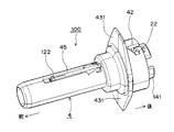
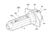
- FIG. 7 is a front perspective view of the entire protective device 100.
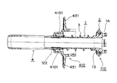
- FIG. 8 is a side sectional view of the protective device 100.
- FIG. 9 is an exploded perspective view of the protective device 100.
- the protective device 100 includes an inner cylinder 1, a ring body 2, a spring 3, and an outer cylinder 4.
- the inner cylinder 1 is a member that holds the inserted syringe 200.
- the ring body 2 is a member constituting a pre-locking mechanism for fixing the inner cylinder body 1 inserted into the outer cylinder body 4 to the outer cylinder body 4.
- the pre-lock mechanism is a mechanism for preventing the protective device 100 from operating (ie, malfunctioning) when it is not intended before use.
- the spring 3 is a member that operates to move the inner cylinder 1 backward relative to the outer cylinder 4 when the protective device 100 is operated, that is, when the pre-lock mechanism is released.
- the outer cylinder 4 is a member that stores the injection needle 202 of the syringe 200 moved rearward together with the inner cylinder 1 in the internal space.
- the inner cylinder 1 and the outer cylinder 4 are preferably made of a transparent resin. According to this, the state of the chemical solution of the syringe 200 inserted into the protective device 100 can be visually confirmed well.
- the transparent resin for example, polycarbonate resin, cycloolefin resin, polypropylene resin and the like can be used.
- FIG. 10 is a front perspective view of the inner cylinder 1.
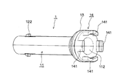
- FIG. 11 is a rear perspective view of the inner cylinder 1.
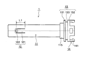
- FIG. 12 is a plan view of the inner cylinder 1.
- FIG. 13 is a side sectional view of the inner cylinder 1.
- the inner cylinder 1 includes a cylindrical main body 11, a tongue portion 12, a ring body attachment portion 13, and a flange attachment portion 14.
- the rear part of the inner cylinder 1 is a large-diameter part 110, and the ring body attaching part 13 and the flange attaching part 14 are provided in the large-diameter part 110.
- the main body 11 has a front end opening 111 and a rear end opening 112, and has an internal space 113 into which the syringe 200 is inserted.
- the tongue 12 is an element that is formed at the front of the main body 11 and constitutes a posterior lock mechanism for fixing the inner cylinder 1 that has moved rearward to the outer cylinder 4.
- the post-lock mechanism is a mechanism for preventing the injection needle 202 stored in the protective device 100 after being actuated from being exposed.
- Two tongue portions 12 are formed at opposite positions in the circumferential direction of the main body 11.
- the tongue portion 12 includes a tongue piece 121 that can be elastically deformed inward and outward with the rear end as a base end, and an outward convex portion 122 at the front end portion of the tongue piece 121.
- the tongue piece 121 is formed by cutting out a part of the peripheral wall of the main body 11.
- the convex part 122 has a trapezoidal shape in plan view.
- the ring body attachment portion 13 includes a front wall portion 131, a rear wall portion 132, and a circumferential groove portion 133 therebetween.
- the heel attachment portion 14 has a claw portion 141 that protrudes rearward for fixing the tub 205 of the syringe main body 204 of the syringe 200 to the inner cylinder 1.
- FIG. 14 is a front perspective view of the ring body 2.
- FIG. 15 is a rear perspective view of the ring body 2.
- FIG. 16 is a plan view of the ring body 2.
- FIG. 17 is a side view of the ring body 2.
- FIG. 18 is a side sectional view of the ring body 2.
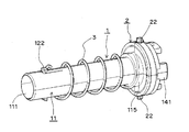
- the ring body 2 includes a cylindrical main body 21, a convex portion 22 provided outward on the outer peripheral surface of the main body 21, a circumferential convex portion 23 provided inward on the inner peripheral surface of the main body 21, And a notch 24 provided at the rear edge.
- Two protrusions 22 are provided at opposite positions in the circumferential direction of the main body 21.
- the convex part 22 has a substantially circular shape in plan view.
- the notches 24 are formed at four locations at equal intervals in the circumferential direction.
- FIG. 19 is a perspective view showing an unloaded state of the spring 3.
- FIG. 20 is a perspective view showing a compressed state of the spring 3.
- the spring 3 has an inner diameter that fits around the peripheral surface 115 of the large-diameter portion 110 of the inner cylinder 1.
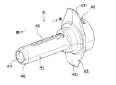
- FIG. 21 is a front perspective view of the outer cylinder 4.
- FIG. 22 is a plan view of the outer cylinder 4.
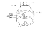
- FIG. 23 is a perspective view of the rear part of the outer cylindrical body 4.
- FIG. 24 is a side sectional view of the outer cylinder 4.
- the outer cylindrical body 4 includes a cylindrical main body 41, a through groove portion 42, a flange portion 43, a spring support portion 44, and a slide groove portion 45.
- the outer cylindrical body 4 has a large-diameter portion 410 at the rear, and the through-groove portion 42, the flange portion 43, and the spring support portion 44 are provided in the large-diameter portion 410.
- the main body 41 has a front end opening 411 and a rear end opening 412, and has an internal space 413 into which the inner cylinder 1 is inserted.
- the large diameter portion 110 of the inner cylinder 1 is inserted into the large diameter portion 410 of the outer cylinder 4.
- the through groove portion 42 is an element that constitutes a pre-locking mechanism together with the ring body 2.
- the through-groove portion 42 includes a linear portion 421 in the front-rear direction that opens at the rear end edge, an inclined portion 422 that extends obliquely rearward from the front end of the linear portion 421, and an engagement that linearly extends rearward from the rear end of the inclined portion 422. And a joint part 423.
- the through groove portions 42 are formed at two locations facing each other in the circumferential direction of the rear portion of the outer cylindrical body 4.
- the flange portion 43 includes two piece portions 431 that extend at a right angle to the main body 41 and in a direction opposite to the main body 41.
- the spring support portion 44 includes a circumferential wall formed so as to support the spring 3 from the inside in the large diameter portion 410.
- a space 4101 for accommodating the front portion of the spring 3 is formed in the large diameter portion 410 by the spring support portion 44.
- the slide groove 45 is an element that constitutes a posterior locking mechanism together with the tongue 12 of the inner cylinder 1.
- the slide groove portions 45 are formed to extend in the front-rear direction from the center portion of the main body 41 to the front portion, and two slide groove portions 45 are formed at positions facing each other in the circumferential direction of the main body 41.
- the slide groove 45 includes a groove main body 451 and an engaging portion 452 formed at the rear end of the groove main body 451. In the state in which the inner cylindrical body 1 before moving backward is fixed to the outer cylindrical body 4, that is, before the protective device 100 is actuated, the slide groove portion 45 has the convex portion 122 of the tongue portion 12 as the groove main body 451.
- the portion 452 is formed so as to be immovably engaged.
- the engaging portion 452 includes two check pieces 4521 that obliquely extend rearward from both sides, and an engaging space 4522.
- the check piece 4521 has elasticity, and is formed so as to allow the convex portion 122 of the tongue 12 to pass from the front to the rear, but not vice versa. Therefore, the engaging portion 452 holds the convex portion 122 that has passed through the check piece 4521 so as not to move within the engaging space 4522.
- FIG. 25 is a perspective view showing a state in which the ring body 2 is attached to the ring body attachment portion 13.
- the front wall portion 131 of the ring body mounting portion 13 has a tapered surface 1311 (see FIG. 26) at the front portion
- the circumferential convex portion 23 of the ring body 2 has a tapered surface 231 (see FIG. 26) at the rear portion. Therefore, the circumferential convex portion 23 can smoothly get over the front wall portion 131. Therefore, the press-fitting work can be performed smoothly. Further, a gap in the front-rear direction and a gap in the inner and outer directions exist between the circumferential convex portion 23 and the circumferential groove portion 133 after the press-fitting, and the circumferential convex portion 23 is connected to the front wall portion 131 and the rear wall portion 132.
- the ring body 2 is externally fitted to the ring body mounting portion 13 so as to be slidable in the circumferential direction and not movable in the front-rear direction, and easily from the ring body mounting portion 13. Do not fall off. Thereby, the ring body 2 is stably attached to the ring body attachment portion 13.
- the inner cylinder 1 to which the ring body 2 is attached is inserted into the unloaded spring 3.
- the rear end portion of the spring 3 is positioned on the peripheral surface 115 of the large diameter portion 110.
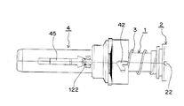
- the inner cylinder 1 in the state of FIG. 28 is inserted into the outer cylinder 4.
- 30 is a plan view showing the state of FIG.
- the front portion of the spring 3 is positioned in the space 4101. Therefore, the spring 3 is stabilized.
- a tapered surface 1221 (see FIG. 13) that faces outward and rearward is formed at the front portion of the convex portion 122, the convex portion 122 is formed when the inner cylindrical body 1 is inserted into the outer cylindrical body 4.
- the inner surface of the outer cylinder 4 is smoothly slid to the slide groove 45. Therefore, the insertion operation of the inner cylinder 1 can be performed smoothly.
- the ring body 2 is slightly rotated in the direction of the arrow R, so that the convex portion 22 is positioned at the engaging portion 423 through the inclined portion 422.
- the rotating operation of the ring body 2 can be easily performed because a finger or a jig can be hooked on the notch 24 (see FIG. 15) on the rear edge of the main body 21.
- the inner cylinder 1, that is, the ring body 2 is urged rearward by the compressed spring 3, the convex portion 22 can be easily inclined only by slightly rotating the ring body 2 in the arrow R direction. It moves to the engaging part 423 through the part 422.
- the convex portion 22 since the engaging portion 423 linearly extends rearward from the rear end of the inclined portion 422, the convex portion 22 is immovable in the circumferential direction and is urged rearward. Therefore, it is located in the engaging portion 423. Therefore, the convex portion 22 cannot be easily detached from the engaging portion 423, and as a result, malfunction is unlikely to occur. That is, according to the pre-lock mechanism configured by the ring body 2 and the through groove portion 42, the convex portion 22 can be firmly held by the engaging portion 423, so that the inner cylinder body 1 before use is firmly attached to the outer cylinder body 4. As a result, malfunction can be prevented.
- the protective device 100 is assembled as described above.
- FIG. 34 is a side sectional view of the state shown in FIG.
- the claw portion 141 of the heel mounting portion 14 includes a wall portion 1411 extending rearward and a convex portion 1412 extending inwardly from the wall portion 1411.
- a space 140 for accommodating the collar 205 is secured between the front surface 1415 of the convex portion 1412 and the rear end surface 16 of the inner cylinder 1.
- the collar 205 passes over the convex portion 1412 from behind and enters the space 140 and is gripped by the claw portion 141 in the space 140.
- the ridge 205 has a substantially square shape when viewed from the rear, the upper side 2051 and the lower side 2052 have an arc shape, and both side pieces 2053 and 2054 have a linear shape. That is, the ridge 205 is a so-called “cut ridge”.
- the wall part 1411 of the claw part 141 is formed so as to follow the flange 205 from four directions. That is, the wall portion 1411 of the upper and lower claw portions 141 has an arc shape, and the wall portions 1411 of the claw portions 141 on both sides have a linear shape. Thereby, the collar 205 does not rotate in the space 140. Moreover, the collar 205 is sandwiched between the convex portion 1412 and the rear end surface 16 of the inner cylindrical body 1. Therefore, the collar 205 can be firmly fixed to the collar mounting portion 14.
- a taper surface 1413 is formed at the front end portion of the convex portion 1412 toward the rear and outward, and the front edge 1414 of the taper surface 1413 is R-processed. Has been. Thereby, the operation
- the inner surface of the large-diameter portion 110 of the inner cylinder 1 is a tapered surface 1101 that opens slightly toward the rear, the syringe 200 can be smoothly guided into the inner cylinder 1.
- the inner cylinder 1 has an inner diameter such that a gap S2 (see FIG. 34) is generated with respect to the syringe main body 204 of the inserted syringe 200. If the size of the gap S2 is too small, it is difficult to insert the syringe body 204, and if it is too large, the syringe body 204 rattles in the inner cylinder 1 or the post-lock mechanism is easily released. Therefore, the gap S2 is set to a dimension that can prevent such a problem.
- the protective device 100 is attached to the syringe 200 as described above.
- the syringe 200 to which the protective device 100 is attached is in the state shown in FIG. In this state, the operator holds the syringe 200 by placing two fingers against the piece 431 of the collar 43 from the front so as to handle a slightly larger syringe. Next, the cap 201 is removed and the injection needle 202 is exposed. Then, the injection needle 202 is inserted into the injection site.
- the piece 431 has a size sufficient to press the finger. Therefore, the operator can stably operate the syringe 200 with the protective device 100.
- the front end portion of the outer cylindrical body 4 has a tapered surface 46 (see FIG. 21) so as to have a small diameter toward the front. Therefore, when the syringe 200 is oriented when the injection needle 202 is inserted, the front end portion of the outer cylinder 4 does not get in the way, and the injection angle can be increased.
- the convex part 22 has the taper surface 221 which follows the inclination part 422 in planar view as FIG. 16 shows, it moves the inclination part 422 smoothly.
- the gap S1 (see FIG. 34) is provided between the outer peripheral surface of the ring body 2 and the inner surface of the large diameter portion 410 of the outer cylinder body 4, the ring body 2 rotates smoothly. Therefore, the convex part 22 moves smoothly.
- the convex portion 22 When the convex portion 22 reaches the front end of the straight portion 421, the convex portion 22 can move rearward through the straight portion 421. That is, the advance lock mechanism is released. As a result, as shown in FIG. 6, the spring 3 is released from the compressed state, and the inner cylinder 1 is pushed backward by the spring 3 to move. Since the inner cylinder 1 holds the syringe 200, the syringe 200 also moves rearward with respect to the outer cylinder 4.
- the inner cylinder 1 moves rearward, the convex portion 122 of the tongue 12 moves rearward along the groove main body 451 of the slide groove 45. That is, the movement of the inner cylinder 1 is guided by the convex portion 122. Therefore, the inner cylinder 1 moves stably. Moreover, since the inner cylinder 1 is supported from the outside by the support part 44 of the large diameter part 410, it moves stably.
- the movement of the inner cylinder 1 stops.
- the distance in the front-rear direction of the slide groove 45 is set to a distance that the inner cylinder 1 moves until the tip of the injection needle 202 is accommodated in the outer cylinder 4. Therefore, when the convex portion 122 is engaged with the engaging portion 452, the injection needle 202 is stored in the internal space 413 of the outer cylinder 4.
- the inner cylinder 1 moved rearward is fixed to the outer cylinder 4.
- the convex portion 122 of the tongue portion 12 can be firmly held by the engaging portion 452 of the slide groove portion 45, so that the inner cylinder body after the operation is operated. 1 can be firmly fixed to the outer cylinder 4, so that the storage state of the injection needle 202 can be maintained firmly, and the injection needle 202 can be prevented from being exposed during storage / disposal after the operation of the protective device 100. As a result, a needle stick accident can be prevented.
- the engagement space 4522 has a trapezoidal shape that is narrower toward the rear in a plan view, and the protrusion 122 has an engagement space 4522 in the plan view. Since the trapezoidal shape is fitted to the projection space 122, the convex portion 122 fits into the engagement space 4522. Moreover, the distance W1 between the tips of the two check pieces 4521 is smaller than the width W2 of the front portion of the convex portion 122. Therefore, the convex part 122 cannot move firmly in the engagement space 4522. Therefore, the post-lock mechanism works firmly.
- the protrusion height H1 (see FIG. 13) of the convex portion 122 is too small, it is difficult to maintain the protrusion height H1 in the engaging portion 452, and if it is too large, the inner cylindrical body 1 is inserted into the outer cylindrical body 4. Since it is in the way, it is set to a dimension that does not cause such trouble.
- the urging force of the spring 3 is set as follows.
- the urging force of the spring 3 is set to be 50 to 400%, preferably 100 to 300% larger than the pressing force.
- the pre-lock mechanism is not released. That is, no malfunction occurs.
- the biasing force of the spring 3 is set to be 100 to 600%, preferably 100 to 300% larger than the sliding resistance.
- the protective device 100 can sufficiently exhibit the protective function.
- the number of tongues 12 is not limited to two and may be one or three or more.
- Two or more tongue portions 12 may be provided at positions that do not face each other in the circumferential direction.
- the convex part 122 of the tongue part 12 may be elliptical, semi-circular, triangular, rectangular or the like in plan view.
- the number of convex portions 22 of the ring body 2 is not limited to two, and one or three or more may be provided.
- Two or more convex portions 22 of the ring body 2 may be provided at positions that do not face each other in the circumferential direction.
- the convex portion 22 of the ring body 2 may be elliptical, rectangular, or the like in plan view.
- the convex part 22 of the ring body 2 may be colored. According to this, the visibility of the advance lock mechanism can be improved.
- the inner cylinder 1 and the outer cylinder 4 may be cylinders having a rectangular cross section. According to this, labeling etc. to the outer cylinder 4 surface can be performed easily.
- FIG. 38 is a view of the protective device 100 of FIG. 37 as viewed from the rear.
- the number of through-groove parts 42 and the position in the circumferential direction need only correspond to the number of convex parts 22 and the position in the circumferential direction.
- the number of the slide groove portions 45 and the position in the circumferential direction only need to correspond to the number of the tongue portions 12 and the position in the circumferential direction.
- the spring support portion 44 may not be continuous to the circumference, and may be, for example, a plurality of rod bodies provided at appropriate intervals in the circumferential direction.
- the scissors 205 of the syringe 200 may have a circular shape (so-called “round scissors”) in the rear view.
- the syringe protection device of the present invention prevents malfunction and allows the syringe to be used safely and effectively, it has great industrial utility value.
Landscapes
- Health & Medical Sciences (AREA)
- Engineering & Computer Science (AREA)
- Heart & Thoracic Surgery (AREA)
- Vascular Medicine (AREA)
- Anesthesiology (AREA)
- Biomedical Technology (AREA)
- Hematology (AREA)
- Life Sciences & Earth Sciences (AREA)
- Animal Behavior & Ethology (AREA)
- General Health & Medical Sciences (AREA)
- Public Health (AREA)
- Veterinary Medicine (AREA)
- Environmental & Geological Engineering (AREA)
- Infusion, Injection, And Reservoir Apparatuses (AREA)
Abstract
Description
(1)使用前の作動を避けるためにロック機構が設けられる場合があるが、当該ロック機構が不確実なものである。それ故、保護器具の輸送時又は保管時、又はプレフィルドシリンジの保護器具へのセット時、又はプレフィルドシリンジを保護器具へセットした後の輸送時又は保管時又は投与時に、すなわち、作動を意図していない時に、作動する恐れがある。すなわち、誤作動する恐れがある。
(2)使用後に格納されている注射針が露出するのを避けるために、ロック機構が設けられる場合があるが、当該ロック機構が不確実なものである。それ故、廃棄等の時に注射針が露出して針刺し事故が起こる恐れがある。
(3)構造が複雑である。
(4)部品点数が多い。
(5)組立が面倒である。
(6)薬液の投与状況を視認するのが困難である。
前端開口と後端開口とを有する外筒体と、
前端開口と後端開口とを有しており、前記外筒体に挿入されており、前記注射器を挿入可能且つ固定可能である、内筒体と、
前記外筒体の後部の内面と前記内筒体の後部の外面との間の円周空間内に、前記内筒体を前記外筒体に対して後方へ付勢するように前後方向圧縮状態で設けられている、スプリングと、
を備えており、
前記スプリングが圧縮状態から解放されると、前記注射針が前記外筒体内に格納されるように前記内筒体が前記外筒体に対して後方へ移動するようになっており、
更に、
前記スプリングを前後方向圧縮状態で維持したまま、前記外筒体に前記内筒体を固定する、解除可能な事前ロック機構を、備えており、
前記事前ロック機構は、
前記内筒体の前記後部に円周方向摺動可能且つ前後方向移動不能に外嵌している、前記内筒体及び前記外筒体とは別体のリング体と、
前記外筒体の前記後部に形成された貫通溝部と、
を備えており、
前記リング体は、円周方向の1箇所以上に外向きの凸部を有しており、
前記凸部は、前記貫通溝部の係合部に係合しており、
前記貫通溝部は、後端縁に開いた前後方向の直線部と、前記直線部の前端から斜め後方へ延びた傾斜部と、前記傾斜部の後端から後方へ直線状に延びた前記係合部と、からなっており、
前記事前ロック機構は、前記スプリングを更に圧縮するように前記内筒体が押された場合に、前記リング体が前記内筒体及び前記外筒体に対して円周方向に回転することにより、前記凸部が前記係合部から出て前記傾斜部を経て前記直線部に入ることによって、解除されるようになっており、
前記内筒体は、前記事前ロック機構が解除されると、前記注射針が前記外筒体内に格納される距離だけ、前記スプリングによって前記外筒体に対して後方へ移動するようになっている、
ことを特徴としている。
(a)事前ロック機構によって、リング体の凸部を貫通溝部の係合部に強固に保持できるので、使用前の内筒体を外筒体に強固に固定でき、その結果、誤作動を防止できる。
(b)更に、事後ロック機構を備えていれば、舌部の凸部をスライド溝部の係合部に強固に保持できるので、作動後の内筒体を外筒体に強固に固定でき、したがって、作動後の保管・廃棄等の際に注射針が露出するのを防止でき、その結果、針刺し事故を防止できる。
図1は、本実施形態の注射器保護器具を注射器に取り付ける直前の様子を示す斜視図である。図1では、注射器保護器具100と注射器200とが一直線上に並んでいる。注射器200は、プレフィルドシリンジであり、先端の注射針202(図3参照)は、キャップ201で覆われている。図2は、保護器具100が注射器200に取り付けられた状態を示す斜視図である。図3は、図2の状態の側面断面図である。注射器200は、保護器具100に挿入されて固定されている。図4は、図2の状態の平面図である。なお、図4では、キャップ201が外されている。図5は、注射器200のプランジャーロッド203が押されて薬液投与が終了した後、更にプランジャーロッド203が押された状態を示す平面図である。図6は、保護器具100が作動して注射針202が保護器具100に格納された状態を示す平面図である。このように、保護器具100は、注射器200に取り付けて用いられると、薬液投与後の注射針202を格納するよう作動するようになっている。
次に、保護器具100の組立作業について説明する。
次に、注射器200への保護器具100の取付作業について、説明する。
保護器具100が取り付けられた注射器200は、図2の状態を呈している。この状態において、操作者は、少し大型の注射器を取り扱うように、2本の指を鍔部43の片部431に前方から当てて、注射器200を把持する。次に、キャップ201を外して、注射針202を露出させる。そして、注射針202を注射部位に刺す。
次に、保護器具100の作動について、説明する。
(a)鍔取付部14に鍔205を取り付ける際には、鍔205が凸部1412を乗り越えるために、内筒体1に前方への押付力が加わる。その場合、事前ロック機構が解除される恐れがある。しかしながら、スプリング3の付勢力は、その押付力に比して大きく設定されているので、事前ロック機構が解除されることはない。すなわち、誤作動は生じない。具体的には、スプリング3の付勢力は、当該押付力より、50~400%好ましくは100~300%大きく、設定されている。
(b)薬液投与のためにプランジャーロッド203を押す際には、シリンジ本体204に対するプランジャーロッド203の摺動抵抗が生じる。その場合、内筒体1に前方への押付力が加わり、事前ロック機構が解除される恐れがある。しかしながら、スプリング3の付勢力は、その摺動抵抗に比して大きく設定されているので、事前ロック機構が解除されることはない。すなわち、誤作動は生じない。具体的には、スプリング3の付勢力は、当該摺動抵抗より、100~600%好ましくは100~300%大きく、設定されている。
(c)スプリング3が圧縮状態から解放されても凸部122が係合部452に至らない場合は、注射針202の格納が不完全になり、また、後方に移動した内筒体1が外筒体4に固定されない。すなわち、保護器具100の保護機能を発揮できない。しかしながら、スプリング3の付勢力は、注射針202が外筒体4内に格納される位置まで、すなわち、凸部122が係合部452に係合する位置まで、内筒体1を移動させることができるように設定されている。したがって、保護器具100は保護機能を十分に発揮できる。
各要素については、次のような変形例を採用できる。
(1)舌部12は、2個に限らず、1個又は3個以上設けられてもよい。
(2)舌部12は、円周方向において対向していない位置に2個以上設けられてもよい。
(3)舌部12の凸部122は、平面視において、楕円形、半円形、三角形、角形等でもよい。
(4)リング体2の凸部22は、2個に限らず、1個又は3個以上設けられてもよい。
(6)リング体2の凸部22は、平面視において、楕円形、角形等でもよい。
(7)リング体2の凸部22は、着色されていてもよい。これによれば、事前ロック機構の視認性を向上できる。
(8)図37に示されるように、内筒体1及び外筒体4は、断面四角形の筒体でもよい。これによれば、外筒体4表面へのラベル貼り等を容易に行うことができる。図38は、図37の保護器具100を後方から見た図である。
(10)スライド溝部45の数及び周方向の位置は、舌部12の数及び周方向の位置に対応していればよい。
(11)スプリング支持部44は、円周に連続していなくてもよく、例えば、円周方向に適当間隔置きに設けられた複数の棒体等でもよい。
(12)注射器200の鍔205は、後方視において円形(いわゆる「丸鍔」)を有してもよい。
容量1mlの注射器200に用いられる保護器具100において、各部の具体的寸法等は、例えば、下記に示すとおりである。
・舌片121の前後方向長さL1(図12参照):3~12mm
・凸部122の突出高さH1(図13参照):0.5~2.5mm
・凸部22の突出高さH2(図18参照):0.5~3mm
・隙間S2(図34参照):0.1~0.6mm
・凸部1412の突出寸法H3(図35参照):0.2~0.7mm
4 外筒体 42 貫通溝部 421 直線部 422 傾斜部 423 係合部
44 支持部 45 スライド溝部 452 係合部 4521 逆止片
100 注射器保護器具 200 注射器 202 注射針
203 プランジャーロッド 204 シリンジ本体
Claims (11)
- 注射器(200)に取り付けて用いられると、薬液投与後の注射針(202)を格納するよう作動するようになっている、注射器保護器具(100)であって、
前端開口(411)と後端開口(412)とを有する外筒体(4)と、
前端開口(111)と後端開口(112)とを有しており、前記外筒体(4)に挿入されており、前記注射器(200)を挿入可能且つ固定可能である、内筒体(1)と、
前記外筒体(4)の後部の内面と前記内筒体(1)の後部の外面との間の円周空間内に、前記内筒体(1)を前記外筒体(4)に対して後方へ付勢するように前後方向圧縮状態で設けられている、スプリング(3)と、
を備えており、
前記スプリング(3)が圧縮状態から解放されると、前記注射針(202)が前記外筒体(4)内に格納されるように前記内筒体(1)が前記外筒体(4)に対して後方へ移動するようになっており、
更に、
前記スプリング(3)を前後方向圧縮状態で維持したまま、前記外筒体(4)に前記内筒体(1)を固定する、解除可能な事前ロック機構を、備えており、
前記事前ロック機構は、
前記内筒体(1)の前記後部に円周方向摺動可能且つ前後方向移動不能に外嵌している、前記内筒体(1)及び前記外筒体(4)とは別体のリング体(2)と、
前記外筒体(4)の前記後部に形成された貫通溝部(42)と、
を備えており、
前記リング体(2)は、円周方向の1箇所以上に外向きの凸部(22)を有しており、
前記凸部(22)は、前記貫通溝部(42)の係合部(423)に係合しており、
前記貫通溝部(42)は、後端縁に開いた前後方向の直線部(421)と、前記直線部(421)の前端から斜め後方へ延びた傾斜部(422)と、前記傾斜部(422)の後端から後方へ直線状に延びた前記係合部(423)と、からなっており、
前記事前ロック機構は、前記スプリング(3)を更に圧縮するように前記内筒体(1)が押された場合に、前記リング体(2)が前記内筒体(1)及び前記外筒体(4)に対して円周方向に回転することにより、前記凸部(22)が前記係合部(423)から出て前記傾斜部(422)を経て前記直線部(421)に入ることによって、解除されるようになっており、
前記内筒体(1)は、前記事前ロック機構が解除されると、前記注射針(202)が前記外筒体(4)内に格納される距離だけ、前記スプリング(3)によって前記外筒体(4)に対して後方へ移動するようになっている、
ことを特徴とする注射器保護器具。 - 後方に移動した前記内筒体(1)を前記外筒体(4)に固定する、事後ロック機構を、更に備えており、
前記事後ロック機構は、
前記外筒体(4)の中央部から前部に渡って前後方向に延びて形成された、少なくとも1つのスライド溝部(45)と、
前記内筒体(1)の前部の周壁に形成された、少なくとも1つの舌部(12)と、
を備えており、
前記舌部(12)は、前後方向に延びており、後端を基端として内外方向に弾性変形可能であり、前端部に外向きの凸部(122)を有しており、
前記スライド溝部(45)は、後方に移動する前の前記内筒体(1)が前記外筒体(4)に固定されている状態においては、前記舌部(12)の前記凸部(122)が前記スライド溝部(45)の内部に位置するように、形成されており、前記内筒体(1)が後方へ移動した状態においては、前記舌部(12)の前記凸部(122)が前記スライド溝部(45)の後端の係合部(452)に移動不能に係合するように、形成されている、
請求項1記載の注射器保護器具。 - 前記事後ロック機構の前記スライド溝部(45)の前記係合部(452)は、前記舌部(12)の前記凸部(122)の後方への移動は許容するが前方への移動は阻止する、逆止片(4521)を、備えている、
請求項2記載の注射器保護器具。 - 前後方向圧縮状態の前記スプリング(3)は、前記注射器(200)のシリンジ本体(204)に対するプランジャーロッド(203)の摺動抵抗に比して大きく、且つ、前記注射器(200)を前記内筒体(1)に固定する際の押付力に比して大きく、且つ、前記注射針(202)が前記外筒体(4)内に格納される位置まで、前記内筒体(1)を移動させることができる、付勢力を、有するように設定されている、
請求項1~3のいずれか一つに記載の注射器保護器具。 - 前記事前ロック機構の前記リング体(2)の前記凸部(22)が、円周方向において対向した2箇所に形成されており、
前記事前ロック機構の前記貫通溝部(42)が、前記外筒体(4)の前記後部の円周方向において対向した2箇所に形成されている、
請求項1~4のいずれか一つに記載の注射器保護器具。 - 前記事後ロック機構の前記スライド溝部(45)が、前記外筒体(4)の周方向において対向した2箇所に形成されており、
前記事後ロック機構の前記舌部(12)が、前記内筒体(1)の周方向において対向した2箇所に形成されている、
請求項2又は請求項2に従属する請求項3~5のいずれか一つに記載の注射器保護器具。 - 前記外筒体(4)の前記後部は、前記円周空間において前記スプリング(3)の前部を内側から支持する支持部(44)を、有している、
請求項1~6のいずれか一つに記載の注射器保護器具。 - 前記外筒体(4)及び前記内筒体(1)が、透明樹脂でできている、
請求項1~7のいずれか一つに記載の注射器保護器具。 - 前記外筒体(4)及び前記内筒体(1)の、本体(41、11)が、断面円形又は断面四角形を、有している、
請求項1~8のいずれか一つに記載の注射器保護器具。 - 前記リング体(2)の外周面と前記外筒体(4)の前記後部の内面との間に、隙間が設けられている、
請求項1~9のいずれか一つに記載の注射器保護器具。 - 注射針(202)と、薬液を貯留したシリンジ本体(204)と、薬液を押し出すプランジャーロッド(203)と、を備えた注射器(200)に、請求項1~10のいずれか一つに記載の注射器保護器具(100)が、取り付けられている、
ことを特徴とする安全注射器。
Priority Applications (4)
| Application Number | Priority Date | Filing Date | Title |
|---|---|---|---|
| EP16875182.4A EP3391922B1 (en) | 2015-12-18 | 2016-09-14 | Syringe protective device |
| CA3008584A CA3008584C (en) | 2015-12-18 | 2016-09-14 | Syringe protecting device |
| KR1020187020560A KR102257266B1 (ko) | 2015-12-18 | 2016-09-14 | 주사기 보호 기구 |
| US16/063,131 US10926040B2 (en) | 2015-12-18 | 2016-09-14 | Syringe protecting device |
Applications Claiming Priority (2)
| Application Number | Priority Date | Filing Date | Title |
|---|---|---|---|
| JP2015247707A JP6009645B1 (ja) | 2015-12-18 | 2015-12-18 | 注射器保護器具 |
| JP2015-247707 | 2015-12-18 |
Publications (1)
| Publication Number | Publication Date |
|---|---|
| WO2017104196A1 true WO2017104196A1 (ja) | 2017-06-22 |
Family
ID=57140182
Family Applications (1)
| Application Number | Title | Priority Date | Filing Date |
|---|---|---|---|
| PCT/JP2016/077147 Ceased WO2017104196A1 (ja) | 2015-12-18 | 2016-09-14 | 注射器保護器具 |
Country Status (7)
| Country | Link |
|---|---|
| US (1) | US10926040B2 (ja) |
| EP (1) | EP3391922B1 (ja) |
| JP (1) | JP6009645B1 (ja) |
| KR (1) | KR102257266B1 (ja) |
| CA (1) | CA3008584C (ja) |
| TW (1) | TWI652088B (ja) |
| WO (1) | WO2017104196A1 (ja) |
Families Citing this family (8)
| Publication number | Priority date | Publication date | Assignee | Title |
|---|---|---|---|---|
| GB201913479D0 (en) * | 2019-09-18 | 2019-10-30 | Nicoventures Trading Ltd | A consumable artcile for use with an apparatus for heating aerosolisable material |
| CN111888581A (zh) * | 2020-09-10 | 2020-11-06 | 苏州赛卫生物科技有限公司 | 带有针头保护装置的安全注射器 |
| CN117255702A (zh) * | 2021-04-28 | 2023-12-19 | 艾斯曲尔医疗公司 | 用于药剂输送装置的盒体单元子组件 |
| CN114949467A (zh) * | 2022-07-11 | 2022-08-30 | 江苏贺利氏医药机械有限公司 | 预装药物注射器保护装置 |
| US20250090767A1 (en) * | 2023-09-18 | 2025-03-20 | Plasto Design Ltd | Safety Device for a Syringe |
| US12303675B1 (en) | 2024-08-29 | 2025-05-20 | Genzyme Corporation | Medicament delivery device |
| US12329954B1 (en) * | 2024-08-29 | 2025-06-17 | Genzyme Corporation | Medicament delivery device |
| US12318582B1 (en) | 2024-08-29 | 2025-06-03 | Genzyme Corporation | Medicament delivery device |
Citations (7)
| Publication number | Priority date | Publication date | Assignee | Title |
|---|---|---|---|---|
| US4923446A (en) * | 1988-04-14 | 1990-05-08 | Page Mary J | Shield for devices capable of penetrating skin |
| US4998924A (en) * | 1989-07-25 | 1991-03-12 | Sherwood Medical Company | Double sleeve safety syringe |
| US20050010136A1 (en) * | 2001-10-08 | 2005-01-13 | Sergio Restelli | Blood sample collection apparatus with a simplified safety device |
| JP2007521845A (ja) * | 2003-10-16 | 2007-08-09 | テクファーマ・ライセンシング・アクチェンゲゼルシャフト | 針カバーを備える注射装置 |
| JP2014503301A (ja) * | 2011-01-04 | 2014-02-13 | サノフィ−アベンティス・ドイチュラント・ゲゼルシャフト・ミット・ベシュレンクテル・ハフツング | プレフィルドシリンジと注射デバイス用の安全デバイス |
| US20140107577A1 (en) * | 2011-06-02 | 2014-04-17 | West Pharmaceutical Services, Inc. | Needle-protection device for a syringe |
| JP2014528303A (ja) * | 2011-10-06 | 2014-10-27 | サノフィ−アベンティス・ドイチュラント・ゲゼルシャフト・ミット・ベシュレンクテル・ハフツング | 針安全デバイス |
Family Cites Families (7)
| Publication number | Priority date | Publication date | Assignee | Title |
|---|---|---|---|---|
| US5201708A (en) | 1992-02-03 | 1993-04-13 | Timothy A. Kershenstine | Self-locking safety syringe |
| US6719730B2 (en) | 1998-04-17 | 2004-04-13 | Becton, Dickinson And Company | Safety shield system for prefilled syringes |
| US6319233B1 (en) | 1998-04-17 | 2001-11-20 | Becton, Dickinson And Company | Safety shield system for prefilled syringes |
| WO2003000323A1 (en) | 2001-06-20 | 2003-01-03 | Becton Dickinson And Company | Safety shield system for prefilled syringes |
| US20050085776A1 (en) | 2003-10-16 | 2005-04-21 | Edgar Hommann | Injection device for administering a fluid product |
| EP2578257A1 (en) * | 2011-10-06 | 2013-04-10 | Sanofi-Aventis Deutschland GmbH | Needle safety device |
| US9248242B2 (en) | 2012-04-20 | 2016-02-02 | Safety Syringes, Inc. | Anti-needle stick safety device for injection device |
-
2015
- 2015-12-18 JP JP2015247707A patent/JP6009645B1/ja active Active
-
2016
- 2016-09-14 KR KR1020187020560A patent/KR102257266B1/ko active Active
- 2016-09-14 US US16/063,131 patent/US10926040B2/en active Active
- 2016-09-14 CA CA3008584A patent/CA3008584C/en not_active Expired - Fee Related
- 2016-09-14 WO PCT/JP2016/077147 patent/WO2017104196A1/ja not_active Ceased
- 2016-09-14 EP EP16875182.4A patent/EP3391922B1/en active Active
- 2016-11-23 TW TW105138363A patent/TWI652088B/zh not_active IP Right Cessation
Patent Citations (7)
| Publication number | Priority date | Publication date | Assignee | Title |
|---|---|---|---|---|
| US4923446A (en) * | 1988-04-14 | 1990-05-08 | Page Mary J | Shield for devices capable of penetrating skin |
| US4998924A (en) * | 1989-07-25 | 1991-03-12 | Sherwood Medical Company | Double sleeve safety syringe |
| US20050010136A1 (en) * | 2001-10-08 | 2005-01-13 | Sergio Restelli | Blood sample collection apparatus with a simplified safety device |
| JP2007521845A (ja) * | 2003-10-16 | 2007-08-09 | テクファーマ・ライセンシング・アクチェンゲゼルシャフト | 針カバーを備える注射装置 |
| JP2014503301A (ja) * | 2011-01-04 | 2014-02-13 | サノフィ−アベンティス・ドイチュラント・ゲゼルシャフト・ミット・ベシュレンクテル・ハフツング | プレフィルドシリンジと注射デバイス用の安全デバイス |
| US20140107577A1 (en) * | 2011-06-02 | 2014-04-17 | West Pharmaceutical Services, Inc. | Needle-protection device for a syringe |
| JP2014528303A (ja) * | 2011-10-06 | 2014-10-27 | サノフィ−アベンティス・ドイチュラント・ゲゼルシャフト・ミット・ベシュレンクテル・ハフツング | 針安全デバイス |
Also Published As
| Publication number | Publication date |
|---|---|
| JP6009645B1 (ja) | 2016-10-19 |
| TW201722497A (zh) | 2017-07-01 |
| CA3008584A1 (en) | 2017-06-22 |
| EP3391922A4 (en) | 2019-09-11 |
| EP3391922B1 (en) | 2020-08-26 |
| KR102257266B1 (ko) | 2021-05-26 |
| TWI652088B (zh) | 2019-03-01 |
| CA3008584C (en) | 2021-03-02 |
| EP3391922A1 (en) | 2018-10-24 |
| KR20180098305A (ko) | 2018-09-03 |
| JP2017109040A (ja) | 2017-06-22 |
| US20180369500A1 (en) | 2018-12-27 |
| US10926040B2 (en) | 2021-02-23 |
Similar Documents
| Publication | Publication Date | Title |
|---|---|---|
| JP6009645B1 (ja) | 注射器保護器具 | |
| US12420029B2 (en) | Injector | |
| JP5824083B2 (ja) | ペン型注射針 | |
| JP5475238B2 (ja) | 注射ペン針用安全シールドシステム | |
| JP5969396B2 (ja) | 通路の有効穴部を狭めるため通路に配置された突出部を備える注射装置 | |
| TWI594784B (zh) | 動力封包鎖 | |
| ES2685829T3 (es) | Inyector automático | |
| US20130131603A1 (en) | Automatic needle guard | |
| AU2006246891B2 (en) | Administration device with forced priming | |
| US10661027B2 (en) | Syringe comprising a bonded needle | |
| US11529473B2 (en) | Safety needles and methods of use thereof | |
| CN101563125A (zh) | 具有被闭锁的保护位置的护针装置 | |
| CN101252962A (zh) | 针罩组件 | |
| US12036393B2 (en) | Injection devices | |
| KR102179345B1 (ko) | 안전 바늘 | |
| JP6211790B2 (ja) | 注射器 | |
| US20230076974A1 (en) | Safety needles and methods of use thereof | |
| KR20200088284A (ko) | 잠금 매커니즘을 갖는 주사기 | |
| US11219720B2 (en) | Safety needle with needle hub, and methods of use thereof | |
| US20040054324A1 (en) | Syringe with retractable needle assembly | |
| JP4361959B2 (ja) | 容器兼用注射器 | |
| JP2023532321A (ja) | 医薬送達器具 | |
| JP2024110418A (ja) | ニードル安全装置 | |
| KR20200126244A (ko) | 주사기 바늘 수납용 케이스 |
Legal Events
| Date | Code | Title | Description |
|---|---|---|---|
| 121 | Ep: the epo has been informed by wipo that ep was designated in this application |
Ref document number: 16875182 Country of ref document: EP Kind code of ref document: A1 |
|
| ENP | Entry into the national phase |
Ref document number: 3008584 Country of ref document: CA |
|
| NENP | Non-entry into the national phase |
Ref country code: DE |
|
| ENP | Entry into the national phase |
Ref document number: 20187020560 Country of ref document: KR Kind code of ref document: A |
|
| WWE | Wipo information: entry into national phase |
Ref document number: 1020187020560 Country of ref document: KR |
|
| WWE | Wipo information: entry into national phase |
Ref document number: 2016875182 Country of ref document: EP |
|
| ENP | Entry into the national phase |
Ref document number: 2016875182 Country of ref document: EP Effective date: 20180718 |