WO2017104231A1 - Moteur à combustion interne - Google Patents
Moteur à combustion interne Download PDFInfo
- Publication number
- WO2017104231A1 WO2017104231A1 PCT/JP2016/079351 JP2016079351W WO2017104231A1 WO 2017104231 A1 WO2017104231 A1 WO 2017104231A1 JP 2016079351 W JP2016079351 W JP 2016079351W WO 2017104231 A1 WO2017104231 A1 WO 2017104231A1
- Authority
- WO
- WIPO (PCT)
- Prior art keywords
- cylinder
- combustion
- expansion
- supercharging
- internal combustion
- Prior art date
- Legal status (The legal status is an assumption and is not a legal conclusion. Google has not performed a legal analysis and makes no representation as to the accuracy of the status listed.)
- Ceased
Links
Images










Classifications
-
- F—MECHANICAL ENGINEERING; LIGHTING; HEATING; WEAPONS; BLASTING
- F01—MACHINES OR ENGINES IN GENERAL; ENGINE PLANTS IN GENERAL; STEAM ENGINES
- F01N—GAS-FLOW SILENCERS OR EXHAUST APPARATUS FOR MACHINES OR ENGINES IN GENERAL; GAS-FLOW SILENCERS OR EXHAUST APPARATUS FOR INTERNAL-COMBUSTION ENGINES
- F01N5/00—Exhaust or silencing apparatus combined or associated with devices profiting by exhaust energy
- F01N5/02—Exhaust or silencing apparatus combined or associated with devices profiting by exhaust energy the devices using heat
-
- F—MECHANICAL ENGINEERING; LIGHTING; HEATING; WEAPONS; BLASTING
- F02—COMBUSTION ENGINES; HOT-GAS OR COMBUSTION-PRODUCT ENGINE PLANTS
- F02B—INTERNAL-COMBUSTION PISTON ENGINES; COMBUSTION ENGINES IN GENERAL
- F02B33/00—Engines characterised by provision of pumps for charging or scavenging
- F02B33/02—Engines with reciprocating-piston pumps; Engines with crankcase pumps
- F02B33/06—Engines with reciprocating-piston pumps; Engines with crankcase pumps with reciprocating-piston pumps other than simple crankcase pumps
- F02B33/22—Engines with reciprocating-piston pumps; Engines with crankcase pumps with reciprocating-piston pumps other than simple crankcase pumps with pumping cylinder situated at side of working cylinder, e.g. the cylinders being parallel
-
- F—MECHANICAL ENGINEERING; LIGHTING; HEATING; WEAPONS; BLASTING
- F02—COMBUSTION ENGINES; HOT-GAS OR COMBUSTION-PRODUCT ENGINE PLANTS
- F02B—INTERNAL-COMBUSTION PISTON ENGINES; COMBUSTION ENGINES IN GENERAL
- F02B61/00—Adaptations of engines for driving vehicles or for driving propellers; Combinations of engines with gearing
-
- F—MECHANICAL ENGINEERING; LIGHTING; HEATING; WEAPONS; BLASTING
- F02—COMBUSTION ENGINES; HOT-GAS OR COMBUSTION-PRODUCT ENGINE PLANTS
- F02B—INTERNAL-COMBUSTION PISTON ENGINES; COMBUSTION ENGINES IN GENERAL
- F02B75/00—Other engines
- F02B75/16—Engines characterised by number of cylinders, e.g. single-cylinder engines
- F02B75/18—Multi-cylinder engines
-
- F—MECHANICAL ENGINEERING; LIGHTING; HEATING; WEAPONS; BLASTING
- F02—COMBUSTION ENGINES; HOT-GAS OR COMBUSTION-PRODUCT ENGINE PLANTS
- F02D—CONTROLLING COMBUSTION ENGINES
- F02D13/00—Controlling the engine output power by varying inlet or exhaust valve operating characteristics, e.g. timing
- F02D13/02—Controlling the engine output power by varying inlet or exhaust valve operating characteristics, e.g. timing during engine operation
- F02D13/06—Cutting-out cylinders
-
- F—MECHANICAL ENGINEERING; LIGHTING; HEATING; WEAPONS; BLASTING
- F02—COMBUSTION ENGINES; HOT-GAS OR COMBUSTION-PRODUCT ENGINE PLANTS
- F02M—SUPPLYING COMBUSTION ENGINES IN GENERAL WITH COMBUSTIBLE MIXTURES OR CONSTITUENTS THEREOF
- F02M26/00—Engine-pertinent apparatus for adding exhaust gases to combustion-air, main fuel or fuel-air mixture, e.g. by exhaust gas recirculation [EGR] systems
- F02M26/02—EGR systems specially adapted for supercharged engines
-
- Y—GENERAL TAGGING OF NEW TECHNOLOGICAL DEVELOPMENTS; GENERAL TAGGING OF CROSS-SECTIONAL TECHNOLOGIES SPANNING OVER SEVERAL SECTIONS OF THE IPC; TECHNICAL SUBJECTS COVERED BY FORMER USPC CROSS-REFERENCE ART COLLECTIONS [XRACs] AND DIGESTS
- Y02—TECHNOLOGIES OR APPLICATIONS FOR MITIGATION OR ADAPTATION AGAINST CLIMATE CHANGE
- Y02T—CLIMATE CHANGE MITIGATION TECHNOLOGIES RELATED TO TRANSPORTATION
- Y02T10/00—Road transport of goods or passengers
- Y02T10/10—Internal combustion engine [ICE] based vehicles
- Y02T10/12—Improving ICE efficiencies
Definitions
- the present invention relates to an internal combustion engine having a supercharging cylinder and an expansion cylinder.
- turbochargers such as turbochargers and superchargers are widely used.
- these turbochargers have been actively developed in recent years, and as a result, their volumetric efficiency, flow rate range, responsiveness, etc. are approaching their limits.
- the exhaust energy that can be used decreases as the thermal efficiency of the internal combustion engine improves.
- an internal combustion engine body provided with a supercharging cylinder that compresses air or an air-fuel mixture (for example, Patent Document 1).
- the supercharging cylinder compresses air or an air-fuel mixture by reciprocation of a piston coupled to a crankshaft of the internal combustion engine via a connecting rod, and supplies the compressed air or air-fuel mixture to the combustion cylinder. Since the supercharging cylinder is driven in conjunction with the crankshaft, there is no supercharging response delay (turbo lag) like a turbocharger, and no exhaust energy is required.
- the burnt gas discharged from the combustion cylinder is supplied to an expansion cylinder provided in the internal combustion engine body, and the piston of the expansion cylinder is driven by the burnt gas, and the burnt gas is discharged from the burned gas. Furthermore, energy is taken out.
- the supercharging cylinder and the expansion cylinder are formed in the internal combustion engine body, so that the layout of each cylinder becomes a problem from the viewpoint of miniaturization and cooling of the internal combustion engine.
- an object of the present invention is to reduce the size and improve the cooling efficiency in an internal combustion engine having a supercharging cylinder and an expansion cylinder.
- an aspect of the present invention includes a supercharging cylinder (8) connected to an intake passage (2), a first combustion cylinder (6) connected to the supercharging cylinder, and the supercharging cylinder.
- the pistons (6A, 7A, 8A, 9A) supported rotatably by the internal combustion engine body and respectively received by the first combustion cylinder, the second combustion cylinder, the supercharging cylinder, and the expansion cylinder are respectively provided.
- a common crankshaft (11) connected by a connecting rod, and the supercharging cylinder and the expansion cylinder are arranged in the axial direction of the crankshaft.
- the supercharging cylinder and the expansion cylinder are arranged in the axial direction of the crankshaft.
- the first combustion cylinder and the second combustion cylinder are disposed at both ends in the axial direction of the crankshaft and are separated from each other, heat dissipation of the internal combustion engine body is promoted. Further, the difference between the intake passage length from the supercharging cylinder to the first combustion cylinder and the intake passage length from the supercharging cylinder to the second combustion cylinder can be reduced, and the expansion cylinder from the first combustion cylinder can be reduced. The difference between the exhaust passage length to the exhaust passage and the exhaust passage length from the second combustion cylinder to the expansion cylinder can be reduced. Thereby, the difference of the output characteristic of each combustion cylinder can be made small.
- the second combustion cylinder when viewed from the direction along the axis of the crankshaft, the second combustion cylinder is disposed at substantially the same angle as the first combustion cylinder, and the supercharging cylinder and the expansion cylinder are
- the first combustion cylinder and the second combustion cylinder may be disposed in a V shape so as to be inclined with respect to each other so as to sandwich at least one of the first combustion cylinder and the second combustion cylinder.
- the second combustion cylinder when viewed from the direction along the axis of the crankshaft, the second combustion cylinder is disposed at substantially the same position as the first combustion cylinder, and the supercharging cylinder and the expansion cylinder are the first combustion cylinder and It is good to arrange
- the supercharging cylinder and the expansion cylinder may be disposed at the same position in the axial direction of the crankshaft.
- the supercharging cylinder and the expansion cylinder can be arranged at substantially the same position in the axial direction of the crankshaft, and the length of the internal combustion engine body in the axial direction of the crankshaft can be shortened.
- the supercharging cylinder is offset to the left side with respect to the first combustion cylinder when viewed from a side along the axis of the crankshaft and the crankshaft becomes clockwise.
- the expansion cylinder may be disposed offset to the right with respect to the first combustion cylinder.
- the supercharging cylinder and the expansion cylinder may be offset from each other in the axial direction of the crankshaft.
- the width of the supercharging cylinder and the expansion cylinder in the direction orthogonal to the axis of the crankshaft can be reduced.
- the first combustion crankpin (14A) corresponding to the first combustion cylinder and the second combustion crankpin (14D) corresponding to the second combustion cylinder are arranged in the same phase
- the supercharged crankpin (14C) corresponding to the supercharged cylinder is disposed on the retard side with respect to the position having a phase difference of 180 ° with respect to the first combustion crankpin, and the expansion crank corresponding to the expansion cylinder.
- the pin (14B) may be disposed on the advance side with respect to a position having a phase difference of 180 ° with respect to the first combustion crankpin.
- crankpin and expansion crankpin overlap each other when viewed from the direction along the axis of the crankshaft.
- the rigidity of the crankshaft is improved.
- a cylinder block including a first bank and a second bank is provided, and each of the first bank and the second bank includes the first combustion cylinder, the second combustion cylinder, and the excess bank. It is good to have a supply cylinder and the said expansion cylinder.
- a V-type engine is configured.
- the first combustion cylinder and the second combustion cylinder may be driven in 4 cycles, and the supercharging cylinder and the expansion cylinder may be driven in 2 cycles.
- each cylinder can be driven efficiently. Since the supercharging cylinder and the expansion cylinder are driven in two cycles, when the combustion cylinder is set to four cycles (stroke), the operation of each cylinder can be made to correspond to each other by providing two combustion cylinders.
- the sum of the reciprocating portion weight of the supercharging cylinder and the reciprocating portion weight of the expansion cylinder is the sum of the reciprocating portion weight of the first combustion cylinder and the reciprocating portion of the second combustion cylinder. It is good that it is substantially the same as the sum of the weight.
- the inertial forces generated in the cylinders cancel each other, and vibration is reduced.
- a first cylinder group (109) having a second combustion cylinder (105) connected to the supply cylinder, a third combustion cylinder (106) connected to the intake passage, and a fourth combustion cylinder connected to the intake passage (108) and an internal combustion engine body (101A) comprising: a second cylinder group (110) having an expansion cylinder (107) connected to the third combustion cylinder and connected to the fourth combustion cylinder;
- An exhaust passage (3) connected to the first combustion cylinder, the second combustion cylinder, and the expansion cylinder, and rotatably supported by the internal combustion engine body, the first combustion cylinder, the first Pistons (103A, 104A, 105A, 106A, 107A, 108A) received in the combustion cylinder, the third combustion cylinder, the fourth combustion cylinder, the supercharging cylinder, and the expansion cylinder are connected by connecting rods,
- the first combustion cylinder, the second combustion cylinder, and the supercharging cylinder are arranged in parallel to each other, and the first combustion cylinder, the axial direction of the crankshaft, A supercharging cylinder, the second combustion cylinder are arranged in this order, and the third combustion cylinder, the fourth combustion cylinder, and the expansion cylinder are arranged in parallel to each other, and the third combustion cylinder is arranged in the axial direction of the crankshaft.
- Arrangement of the expansion cylinder and the fourth combustion cylinder in this order It is possible to provide an internal combustion engine (100), characterized in that.
- a cylinder deactivation mechanism (155A) that selectively deactivates at least one of the first cylinder group and the second cylinder group may be provided.
- an internal combustion engine having two cylinder groups capable of cylinder deactivation can be configured.
- first cylinder group and the second cylinder group may be arranged in a V shape.
- first cylinder group and the second cylinder group may be arranged in parallel to each other.
- the downstream end of the intake passage (4) is connected to the first branch passage (2E) connected to the supercharging cylinder, and to the third combustion cylinder and the fourth combustion cylinder.
- a second branch passage (2F) the first branch passage is provided with a first throttle valve (2E), the second branch passage is provided with a second throttle valve (2F), and the internal combustion engine EGR provided with one end connected to the exhaust passage and the other end connected to the downstream portion of the first branch passage from the first throttle valve for supplying combustion gas to the intake passage It is good to have a passage (5A).
- the thermal efficiency of the internal combustion engine is improved.
- the intake valve becomes relatively large due to the throttle valve being throttled when the load is low, and the pumping loss is relatively large.
- EGR gas is introduced into the intake passage.
- the negative suction pressure can be reduced and the pumping loss can be reduced.
- the introduction of EGR gas reduces the combustion temperature in the combustion cylinder and reduces the cooling loss. Further, knocking is suppressed by a decrease in the combustion chamber temperature accompanying a decrease in the combustion temperature.
- the other end of the EGR passage may be branched and connected to a downstream portion of the second branch passage with respect to the second throttle valve.
- the EGR gas is also supplied to the third combustion cylinder and the fourth combustion cylinder, and it becomes possible to reduce the pumping loss, the cooling loss, and the knocking.
- the sum of the reciprocating portion weight of the supercharging cylinder and the reciprocating portion weight of the expansion cylinder is the weight of the reciprocating portion of the first combustion cylinder and the reciprocating portion of the second combustion cylinder.
- the sum of the weight, the weight of the reciprocating portion of the third combustion cylinder, and the weight of the reciprocating portion of the fourth combustion cylinder may be substantially the same.
- inertial forces generated in the cylinders cancel each other, and vibration is reduced.
- FIG. 1 is a configuration diagram of an internal combustion engine according to a first embodiment.
- A Perspective side view showing the positional relationship between each cylinder and each crankpin according to the first embodiment
- B Perspective plan view showing the positional relationship between each cylinder and each crankpin according to the first embodiment.
- the perspective side view which shows the valve mechanism based on 1st Embodiment The top view which shows the valve mechanism based on 1st Embodiment.
- Operation stroke diagram of the internal combustion engine according to the first embodiment (A) Top view, (B) Side view, (C) Front view showing the arrangement of each cylinder of an internal combustion engine according to a modification of the first embodiment (A) Top view which shows arrangement
- Operation stroke diagram of internal combustion engine according to second embodiment
- the top view which shows arrangement
- the top view which shows the crankshaft which concerns on 3rd Embodiment (B) The perspective side view which shows the positional relationship of each cylinder and each crankpin which concerns on 3rd Embodiment.
- the internal combustion engine 1 includes an internal combustion engine main body 1 ⁇ / b> A, an intake device 2, an exhaust device 3, an intercooler 4, and an EGR device 5.
- the internal combustion engine body 1A includes a cylinder block 1B, a cylinder head 1C coupled to the upper part of the cylinder block 1B, a head cover 1D coupled to the upper part of the cylinder head 1C, and an oil pan 1E coupled to the lower part of the cylinder block 1B. And have.
- 1st combustion cylinder 6, 2nd combustion cylinder 7, supercharging cylinder 8, and expansion cylinder 9 are formed in the upper part of cylinder block 1B.
- the upper ends of the cylinders 6 to 9 are open to the upper end surface of the cylinder block 1B and are closed by the cylinder head 1C.
- the lower ends of the cylinders 6 to 9 are connected to a crank chamber formed in the lower part of the cylinder block 1B.
- a crankshaft 11 is disposed in the crank chamber.
- the crankshaft 11 is rotatably supported by the cylinder block 1B.
- the axis A of the crankshaft 11 extends to the left and right.
- the cylinders 6 to 9 are arranged in the order of the first combustion cylinder 6, the expansion cylinder 9, the supercharging cylinder 8, and the second combustion cylinder 7 from one side (right side) in the direction along the axis A of the crankshaft 11. ing. That is, in the direction along the axis A, the expansion cylinder 9 and the supercharging cylinder 8 are disposed between the first combustion cylinder 6 and the second combustion cylinder 7.
- the plane including the axis A of the crankshaft 11 and extending substantially vertically is a reference plane
- the axes of the first combustion cylinder 6 and the second combustion cylinder 7 are generally arranged on the reference plane.
- the axes of the first combustion cylinder 6 and the second combustion cylinder 7 may be arranged slightly offset back and forth with respect to the reference plane.
- the reference plane may be inclined back and forth around the axis A of the crankshaft 11.
- the axis of the expansion cylinder 9 is inclined forward with respect to the reference plane, and the axis of the supercharging cylinder 8 is inclined backward with respect to the reference plane.
- the expansion cylinder 9 and the supercharging cylinder 8 are arranged in a so-called V shape.
- the expansion cylinder 9 and the supercharging cylinder 8 overlap each other when viewed from the front-rear direction. In this way, the length of the internal combustion engine 1 in the direction of the axis A can be shortened.
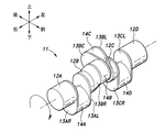
- the crankshaft 11 includes, from the right side, the first journal 12A, the right first arm 13AR, the first crankpin 14A, the left first arm 13AL, the second journal 12B, the right second arm 13BR, the second Crank pin 14B, central second arm 13BC, third crank pin 14C, left second arm 13BL, third journal 12C, right third arm 13CR, fourth crank pin 14D, left third arm 13CL, fourth journal 12D Have.
- the first to fourth journals 12 (12A to 12D) are arranged coaxially with each other and constitute the rotation shaft of the crankshaft 11.
- the left and right first arms 13AR and 13AL, the left and right second arms 13BR and 13BL, and the left and right third arms 13CR and 13CL extend in the radial direction from the journals 12, respectively.
- the central second arm 13BC extends in the circumferential direction of the crankshaft 11.
- the first to fourth crank pins 14 (14A to 14D) are arranged in parallel with the axis A of the crankshaft 11, respectively.
- crankpin 14B and the third crankpin 14C may be arranged so that at least a part thereof overlaps when viewed from the direction along the axis A of the crankshaft 11. . If it does in this way, the rigidity of crankshaft 11 will improve.
- the first combustion piston 6A received in the first combustion cylinder 6 so as to be able to reciprocate is connected to the first crank pin 14A via a connecting rod (not shown).
- the expansion piston 9A received in the expansion cylinder 9 so as to be able to reciprocate is connected to the second crankpin 14B via a connecting rod.
- the supercharging piston 8A received in the supercharging cylinder 8 so as to be able to reciprocate is connected to the third crankpin 14C via a connecting rod.
- the second combustion piston 7A received in the second combustion cylinder 7 so as to be able to reciprocate is connected to the fourth crankpin 14D via a connecting rod.
- the sum of the reciprocating part weight of the supercharging cylinder 8 and the reciprocating part weight of the expansion cylinder 9 is substantially equal to the sum of the reciprocating part weight of the first combustion cylinder 6 and the reciprocating part weight of the second combustion cylinder 7. Is set. As a result, inertial forces generated in the cylinders 6 to 9 cancel each other, and vibration is reduced.
- the first crankpin 14A and the fourth crankpin are viewed along the axis A of the crankshaft 11 and viewed from the side (right side) in which the crankshaft 11 is clockwise.
- 14D is arranged in the same phase (with a crank angle of 0 °).
- the second crankpin 14B and the third crankpin 14C are arranged so that the expansion piston 9A and the supercharging piston 8A are positioned near the top dead center when the first combustion piston 6A is at the bottom dead center. And the phase difference is set.
- the second crankpin 14B may be slightly advanced so that the expansion piston 9A is at a position past the top dead center when the first combustion piston 6A is at the bottom dead center.
- the third crank pin 14C may be slightly retarded so that when the first combustion piston 6A is at the bottom dead center, the supercharged piston 8A is at a position before the top dead center.
- Both the stroke volume of the expansion cylinder 9 and the stroke volume of the supercharging cylinder 8 are set larger than both the stroke volume of the first combustion cylinder 6 and the stroke volume of the second combustion cylinder 7.
- the stroke volumes of the first combustion cylinder 6 and the second combustion cylinder 7 are equal, and the stroke volumes of the expansion cylinder 9 and the supercharging cylinder 8 are set equal.
- the stroke volume of the expansion cylinder 9 and the stroke volume of the supercharging cylinder 8 may be set to be different from each other.
- the strokes of the cylinders 6 to 9 are set to be equal, and the diameters of the expansion cylinder 9 and the supercharging cylinder 8 are set to be larger than the diameters of the combustion cylinders.
- the internal combustion engine 1 connects a supercharging intake passage 21 that connects an intake device 2 that constitutes an intake passage and a supercharging cylinder 8, and a supercooling cylinder 8 and a cooler inlet 4 ⁇ / b> A of the intercooler 4.
- a supercharged exhaust passage 22 a first intake passage 23 connecting the first outlet 4B of the intercooler 4 and the first combustion cylinder 6, and a first exhaust passage 24 connecting the first combustion cylinder 6 and the expansion cylinder 9.
- a second intake passage 25 that connects the second outlet 4C of the intercooler 4 and the second combustion cylinder 7, a second exhaust passage 26 that connects the second combustion cylinder 7 and the expansion cylinder 9, and an expansion cylinder 9.
- An expansion exhaust passage 27 is connected to the exhaust device 3 constituting the exhaust passage.
- Each of the passages 21 to 27 is constituted by a passage formed in the cylinder head 1C or a pipe member.
- the intake device 2 has an air inlet 2A, an air cleaner 2B, a throttle valve 2C, and an intake header 2D from the upstream side.
- the supercharged intake passage 21 is connected to the downstream end of the intake device 2.
- the exhaust device 3 includes a three-way catalyst 3A, a silencer 3B, and an exhaust outlet 3C from the upstream side.
- the expansion exhaust passage 27 is connected to the upstream end of the exhaust device 3.
- the intercooler 4 is disposed in the vicinity of the supercharging cylinder 8 and above and behind the cylinder head 1C and the head cover 1D. More specifically, the intercooler 4 may be disposed behind a valve operating mechanism 40 described later.
- the intercooler 4 may be an air-cooled heat exchanger or a known heat exchanger that uses water or another refrigerant.
- the intercooler 4 includes the cooler inlet 4A connected to the supercharged exhaust passage 22, the first outlet 4B connected to the first intake passage 23, and the second outlet connected to the second intake passage 25. 4C.
- the intercooler 4 cools the air (air mixture) flowing from the cooler inlet 4A to the first outlet 4B and the second outlet 4C. As shown in FIG.
- the intercooler 4 extends to the left and right in parallel to the axis A of the crankshaft 11, and has a right end facing the first combustion cylinder 6 and a left end facing the second combustion cylinder 7.
- the cooler inlet 4 ⁇ / b> A is provided at the center in the longitudinal direction of the intercooler 4, the first outlet 4 ⁇ / b> B is provided at the right end of the intercooler 4, and the second outlet 4 ⁇ / b> C is provided at the left end of the intercooler 4.
- the opening end on the second combustion cylinder 7 side of the two exhaust passages 26 and the opening end on the expansion cylinder 9 side of the expansion exhaust passage 27 are branched into two forks and connected to the cylinders 6-9.
- a supercharged intake valve 31 that opens and closes the supercharged intake passage 21 is provided at the boundary between each of the branched opening ends of the supercharged intake passage 21 and the supercharged cylinder 8.
- a supercharging exhaust valve 32 that opens and closes the supercharging exhaust passage 22 is provided at the boundary between each of the branched opening ends of the supercharging exhaust passage 22 and the supercharging cylinder 8.
- a first intake valve 33 that opens and closes the first intake passage 23 is provided at each boundary between the branched opening ends of the first intake passage 23 and the first combustion cylinder 6.
- a first exhaust valve 34 that opens and closes the first exhaust passage 24 is provided at the boundary between each branched opening end of the first exhaust passage 24 and the first combustion cylinder 6.
- a second intake valve 35 that opens and closes the second intake passage 25 is provided at each boundary between the branched end of the second intake passage 25 and the second combustion cylinder 7.
- a second exhaust valve 36 for opening and closing the second exhaust passage 26 is provided at the boundary between each of the branched open ends of the second exhaust passage 26 and the second combustion cylinder 7.
- An expansion exhaust valve 37 for opening and closing the expansion exhaust passage 27 is provided at the boundary between each of the branched opening ends of the expansion exhaust passage 27 and the expansion cylinder 9.
- the supercharged intake valve 31, the supercharged exhaust valve 32, the first intake valve 33, the first exhaust valve 34, the second intake valve 35, the second exhaust valve 36, and the expansion exhaust valve 37 are known poppet valves, Each passage is normally closed by being biased by a valve spring (not shown), and each passage 21 to 27 is opened at a predetermined timing by the operation of the valve mechanism 40. On-off valves are not provided at the boundary between the first exhaust passage 24 and the expansion cylinder 9 and at the boundary between the second exhaust passage 26 and the expansion cylinder 9.
- the valve mechanism 40 is disposed in a valve chamber 1F formed between the cylinder head 1C and the head cover 1D.
- the valve mechanism 40 includes a front camshaft 41 and a rear camshaft 42 that extend in parallel with the crankshaft 11, and a front rocker shaft 43 and a rear rocker shaft 44.
- the front camshaft 41 and the front rocker shaft 43 are generally disposed above the expansion cylinder 9, and the rear camshaft 42 and the rear rocker shaft 44 are generally disposed above the first combustion cylinder 6 and the second combustion cylinder 7.
- the front camshaft 41 and the rear camshaft 42 are connected to the crankshaft 11 by a power transmission mechanism including a timing chain and a sprocket (not shown), and rotate at half the rotational speed of the crankshaft 11.
- a first exhaust rocker arm 43A, an expansion exhaust rocker arm 43B, and a second exhaust rocker arm 43C are rotatably supported on the front rocker shaft 43.
- a first intake rocker arm 44A, a supercharged intake rocker arm 44B, a supercharged exhaust rocker arm 44C, and a second intake rocker arm 44D are rotatably supported on the rear rocker shaft 44.
- the first exhaust rocker arm 43A opens the first exhaust valve 34
- the expansion exhaust rocker arm 43B opens the expansion exhaust valve 37
- the first exhaust rocker arm 43B opens by pressing each cam crest formed on the front camshaft 41 at a predetermined timing.
- the two exhaust rocker arm 43C opens the second exhaust valve 36.
- the first intake rocker arm 44 ⁇ / b> A opens the first intake valve 33 and the supercharged intake rocker arm 44 ⁇ / b> B opens the supercharged intake valve 31 by pressing each cam crest formed on the rear camshaft 42 at a predetermined timing.
- the supercharged exhaust rocker arm 44C opens the supercharged exhaust valve 32
- the second intake rocker arm 44D opens the second intake valve 35.
- the front camshaft 41 and the rear camshaft 42 that open and close the valves 33 to 36 that open and close the first combustion cylinder 6 and the second combustion cylinder 7 are the valves 31 and 32 that open and close the supercharging cylinder 8.
- the valve 37 which opens and closes the expansion cylinder 9 is driven to open and close.
- the supercharging cylinder 8 is driven in two cycles having an intake stroke and a compression stroke while the crankshaft 11 rotates once.
- the intake stroke is a period during which the supercharging piston 8A descends from the top dead center to the bottom dead center.
- the supercharging intake valve 31 is opened, and the supercharging exhaust valve 32 is closed.
- Air (air mixture) is sucked into the supercharging cylinder 8.
- the compression stroke is a period in which the supercharging piston 8A rises from the bottom dead center to the top dead center.
- the supercharging intake valve 31 is closed, and the supercharging exhaust valve 32 is opened, whereby the supercharging cylinder 8 is supercharged. Air (air mixture) is sent to the air supply / exhaust passage 22 and compressed.
- the first combustion cylinder 6 and the second combustion cylinder 7 are driven in four cycles in which an intake stroke, a compression stroke, an expansion stroke, and an exhaust stroke are performed while the crankshaft 11 rotates twice, similarly to a known four-cycle reciprocating engine. Is done.
- the first combustion cylinder 6 and the second combustion cylinder 7 are out of phase by 360 °.
- the expansion cylinder 9 is driven in two cycles having an expansion stroke and an exhaust stroke while the crankshaft 11 rotates once.
- the expansion stroke is a period in which the expansion piston 9A descends from the top dead center to the bottom dead center.
- the expansion exhaust valve 37 is closed, so that the expansion cylinder 9 is already moved from the first exhaust passage 24 or the second exhaust passage 26 to the expansion cylinder 9.
- the combustion gas flows and the expansion piston 9A is pushed down.
- the exhaust stroke is a period during which the expansion piston 9A rises from the bottom dead center to the top dead center. At this time, the combustion exhaust gas flows from the expansion cylinder 9 to the expansion exhaust passage 27 by opening the expansion exhaust valve 37.
- the first compression stroke of the supercharging cylinder 8 is performed at the same timing as the intake stroke of one of the first combustion cylinder 6 and the second combustion cylinder 7.
- the second compression stroke is performed at the same timing as the other intake stroke of the first combustion cylinder 6 and the second combustion cylinder 7.
- air air mixture
- the stroke volume of the supercharging cylinder 8 is larger than the stroke volume of each of the first combustion cylinder 6 and the second combustion cylinder 7, the air (air mixture) supplied to the first combustion cylinder 6 or the second combustion cylinder 7 is Pressurized. That is, the supercharging cylinder 8 can supercharge the first combustion cylinder 6 or the second combustion cylinder 7.
- the first expansion stroke of the expansion cylinder 9 is performed at the same timing as the exhaust stroke of one of the first combustion cylinder 6 and the second combustion cylinder 7, and the second expansion stroke of the expansion cylinder 9 is performed.
- the expansion stroke is performed at the same timing as the other exhaust stroke of the first combustion cylinder 6 and the second combustion cylinder 7.
- each stroke of the supercharging cylinder 8 may be retarded with respect to the timing shown in FIG. In this case, in the latter stage of the intake stroke of the first combustion cylinder 6 and the second combustion cylinder 7, the compression effect by the supercharging cylinder 8 becomes strong, and the supercharging pressure (supercharging efficiency) increases.
- each stroke of the expansion cylinder 9 may be advanced with respect to the timing shown in FIG. In this case, when the exhaust strokes of the first combustion cylinder 6 and the second combustion cylinder 7 are started, the expansion piston 9A has already been lowered in the expansion cylinder 9, so that negative pressure is generated in the expansion cylinder 9, and the suction effect is caused.
- the retarding of the supercharging cylinder 8 and the advancement of the expansion cylinder 9 are achieved by adjusting the positions of the second crankpin 14B and the third crankpin 14C and adjusting the positions of the supercharging cylinder 8 and the expansion cylinder 9.
- the EGR device 5 is provided so as to connect the exhaust device 3 and the intake device 2.
- the EGR device 5 is an EGR passage that connects a passage portion downstream of the three-way catalyst 3A of the exhaust device 3 and upstream of the silencer 3B and a passage portion of the intake device 2 downstream of the throttle valve 2C. 5A.
- an end portion on the exhaust side of the EGR passage 5A may be connected to a passage portion on the upstream side of the three-way catalyst 3A.
- the EGR device 5 includes an EGR cooler 5B and an EGR valve 5C provided in the EGR passage 5A in order from the exhaust side.
- the EGR cooler 5B is an air-cooled or water-cooled heat exchanger, and cools the EGR gas (burned gas) passing through the inside.
- the EGR valve 5C is a control valve whose opening degree can be adjusted, and adjusts the flow rate of EGR gas flowing through the EGR passage 5A.
- the passage portion on the upstream side of the three-way catalyst 3A of the exhaust device 3 has a high pressure due to the exhaust gas discharged from the expansion cylinder 9, and the passage portion on the downstream side of the throttle valve 2C in the intake passage sucks in the supercharging cylinder 8. Therefore, the EGR gas flows through the EGR passage 5A from the exhaust side to the intake side due to the pressure difference.
- the internal combustion engine 1 has a first injector 46 and a second injector 47 that inject gasoline as fuel.
- the first injector 46 is provided to supply fuel to at least one of the supercharging cylinder 8 and the first and second combustion cylinders 6, 7, and is a passage portion on the downstream side of the throttle valve 2 ⁇ / b> C of the intake device 2.
- the supercharging intake passage 21, the supercharging cylinder 8, the first intake passage 23, the first combustion cylinder 6, the second intake passage 25, and the second combustion cylinder 7 are provided.
- an example in which the first injector 46 is provided in the supercharging intake passage 21 is shown.
- the first injector 46 is provided downstream of the intercooler 4
- the first injector 46 is provided in each passage branched corresponding to each combustion cylinder 6, 7.
- one first injector 46 is provided for the first intake passage 23 or the first combustion cylinder 6 and one for the second intake passage 25 or the second combustion cylinder 7.
- the first injector 46 includes the supercharging cylinder 8 and is provided on the upstream side, a long distance to the first combustion cylinder 6 and the second combustion cylinder 7 is ensured, and the compression and stirring action in the supercharging cylinder 8 is ensured. Therefore, the homogenization of the air-fuel mixture is improved.
- the density of the intake air supplied to the supercharging cylinder 8 is increased by the cooling of the intake air accompanying the vaporization of the fuel, the supercharging efficiency of the supercharging cylinder 8 is improved and the thermal efficiency is improved.
- the second injector 47 is provided in any of the first exhaust passage 24, the second exhaust passage 26, and the expansion cylinder 9 in order to supply fuel to the expansion cylinder 9.
- the fuel injection amount of the first injector 46 is controlled so that the air-fuel ratio becomes leaner than the stoichiometric air-fuel ratio. Thereby, in each combustion cylinder, the lean combustion advantageous for fuel consumption is performed.
- the first combustion cylinder 6 and the second combustion cylinder 7 are each provided with a spark plug (not shown), and combustion is started by the spark of the spark plug.
- the second injector 47 directly injects fuel into the expansion cylinder 9.
- the fuel injection amount is controlled so that the air-fuel ratio becomes substantially the stoichiometric air-fuel ratio together with the fuel injection amounts by all the first injectors 46.
- the expansion cylinder 9 is provided with a spark plug, and combustion is started by the spark of the spark plug.
- the expansion piston 9 ⁇ / b> A is driven by the combustion energy of the fuel from the second injector 47 in addition to the energy of the already burned gas generated in the first combustion cylinder 6 or the second combustion cylinder 7.
- the burnt gas (exhaust gas) flowing through the three-way catalyst 3A becomes a gas burned at the stoichiometric air-fuel ratio by the fuel injection by the second injector 47, the three-way catalyst 3A can function properly. Further, since the combustion energy of the fuel injected from the second injector 47 is used for driving the expansion cylinder 9, the fuel consumption can be further improved.
- the ignition plug of the expansion cylinder 9 may be omitted, and the fuel injected from the second injector 47 may be self-ignited. Further, the fuel injection by the second injector 47 may be stopped.
- the internal combustion engine 1 introduces EGR gas into the intake device 2 by the EGR device 5, the opening of the throttle valve 2 ⁇ / b> C at a low load is made relatively large to reduce the pumping loss caused by the supercharging cylinder 8. Can do. Further, the introduction of EGR gas lowers the combustion temperature in the combustion cylinders 6 and 7 and reduces the cooling loss. Further, knocking is suppressed by a decrease in the combustion chamber temperature accompanying a decrease in the combustion temperature. Since the supercharging cylinder 8 is driven by the crankshaft 11, the supercharging response when the load fluctuates is high.
- the introduction amount of the EGR gas into the intake device 2 increases due to the negative pressure generated by the supercharging cylinder 8, the introduction amount of the EGR gas increases with good responsiveness when the load increases. Therefore, knocking is suppressed in the first and second combustion cylinders 6 and 7, and ignition timing retard is unnecessary. Thereby, the thermal efficiency of the internal combustion engine 1 increases.
- EGR gas is introduced into the intake passage by the suction negative pressure of the supercharging cylinder 8. Further, since the EGR gas does not pass through the throttle valve 2C, soot adhesion to the throttle valve 2C is suppressed. In addition, when the EGR gas cooled by the EGR cooler 5B is introduced into the combustion cylinders 6 and 7, the temperature of the combustion cylinders 6 and 7 is lowered, knocking is further suppressed, and the combustion temperature is lowered. Thus, the cooling loss is reduced.
- lean combustion is performed in each of the combustion cylinders 6 and 7 with the fuel supplied from the first injector 46 to improve thermal efficiency. Then, the fuel supplied from the second injector 47 makes the air-fuel ratio of the exhaust gas the stoichiometric air-fuel ratio suitable for the activity of the three-way catalyst 3A. Further, since the fuel supplied from the second injector 47 is driven by the expansion cylinder 9 by being burned in the expansion cylinder 9, a reduction in fuel consumption is suppressed.
- the first combustion cylinder 6 and the second combustion cylinder 7 are disposed at both ends in the axis A direction of the crankshaft 11 and are separated from each other, heat dissipation of the internal combustion engine body 1A is promoted. Further, since the supercharging cylinder 8 is disposed between the first combustion cylinder 6 and the second combustion cylinder 7, the intake passage length from the supercharging cylinder 8 to the first combustion cylinder 6, and the supercharging cylinder 8 The difference from the intake passage length to the second combustion cylinder 7 can be reduced. Further, since the expansion cylinder 9 is disposed between the first combustion cylinder 6 and the second combustion cylinder 7, the exhaust passage length from the first combustion cylinder 6 to the expansion cylinder 9 and the expansion from the second combustion cylinder 7 are expanded. The difference from the exhaust passage length to the cylinder 9 can be reduced. As a result, the intake amount and the exhaust amount to each combustion cylinder 6 and 7 become uniform.
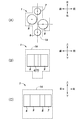
- the supercharging cylinder 8 and the expansion cylinder 9 are inclined with respect to the reference plane and arranged in a V shape, but as shown in FIGS. 7 (A) to (C).
- the first combustion cylinder 6, the second combustion cylinder 7, the supercharging cylinder 8, and the expansion cylinder 9 may be arranged such that their axes are parallel to each other. In this case, from the right side, the first combustion cylinder 6, the expansion cylinder 9, the supercharging cylinder 8, and the second combustion cylinder 7 are arranged in this order, and the first combustion cylinder 6 and the second combustion cylinder 7 are arranged on the reference plane.
- the expansion cylinder 9 may be offset forward with respect to the reference plane, and the supercharging cylinder 8 may be offset backward with respect to the reference plane.
- the expansion cylinder 9 may be offset backward with respect to the reference plane, and the supercharging cylinder 8 may be offset forward with respect to the reference plane.
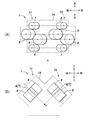
- the structure of the 1st combustion cylinder 6, the supercharging cylinder 8, the expansion cylinder 9, and the 2nd combustion cylinder 7 of the internal combustion engine 1 which concerns on 1st Embodiment is included as one cylinder group, respectively.
- Two cylinder banks 71 and 72 may be formed and arranged in a V shape. That is, a total of eight cylinder internal combustion engines having four combustion cylinders, two supercharging cylinders 8 and two expansion cylinders 9 may be used.
- the cylinder groups of the cylinder banks 71 and 72 are preferably arranged so as to be rotationally symmetric with respect to an axis extending vertically from the center of the internal combustion engine.
- each cylinder group may be arranged in parallel with each other as in the above-described modified example (see FIG. 7), and V as in the internal combustion engine 1 according to the first embodiment. It may be arranged in a mold. Further, the cylinder groups may be arranged in parallel with each other, or may be arranged in a horizontally opposed manner.
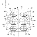
- the internal combustion engine main body 101A of the internal combustion engine 100 is coupled to a crankcase 101B that rotatably supports a crankshaft 111 extending in the left-right direction and an upper portion of the crankcase 101B.
- the front cylinder block 101C and the rear cylinder block 101D extending left and right respectively, the front cylinder head 101E and the rear cylinder head 101F coupled to the upper portions of the front and rear cylinder blocks 101C and 101D, and the front and rear cylinder heads 101E and 101F, respectively.
- the front head cover 101G and the rear head cover 101H are respectively coupled to the upper part of the crankcase 101B, and the oil pan 101J is coupled to the lower part of the crankcase 101B.
- the front cylinder block 101C and the rear cylinder block 101D extend to the left and right, respectively.
- a first combustion cylinder 103, a supercharging cylinder 104, and a second combustion cylinder 105 are formed in series from the right side.
- a third combustion cylinder 106, an expansion cylinder 107, and a fourth combustion cylinder 108 are formed in series from the right side.
- the upper ends of the cylinders 103 to 108 open to the upper end surfaces of the front and rear cylinder blocks 101C and 101D, and are closed by cylinder heads 101E and 101F.
- the lower ends of the cylinders 103 to 108 are connected to a crank chamber formed in the lower part of the cylinder block 1B.
- the first combustion cylinder 103, the supercharging cylinder 104, and the second combustion cylinder 105 constitute a first cylinder group 109
- the third combustion cylinder 106, the expansion cylinder 107, and the fourth combustion cylinder 108 constitute a second cylinder group 110.
- the first to fourth combustion cylinders 103, 105, 106, 108 are formed to have the same size.
- the supercharging cylinder 104 and the expansion cylinder 107 are formed to be the same size as each other and larger than the first combustion cylinder 103.
- the first to fourth combustion cylinders 103, 105, 106, 108 and the supercharging cylinder 104 and the expansion cylinder 107 are formed to have the same length, and the supercharging cylinder 104 and the expansion cylinder 107 are formed of the first to fourth combustion cylinders 103.
- 105, 106, and 108 are formed with a larger diameter.
- the cylinders 103 to 105 of the first cylinder group 109 are inclined backward by the same angle with respect to a reference plane that includes the axis A of the crankshaft 111 and extends substantially vertically, and the cylinders 106 to 108 of the second cylinder group 110 It is tilted forward by the same angle. That is, the first cylinder group 109 and the second cylinder group 110 are V-shaped.
- the first combustion cylinder 103 and the third combustion cylinder 106 are disposed at the same position
- the supercharging cylinder 104 and the expansion cylinder 107 are disposed at the same position
- the second combustion cylinder 105 and the fourth combustion cylinder 108 are disposed.
- the crankshaft 111 includes a first journal 112A, a right first arm 113AR, a first crank pin 114A, a left first arm 113AL, a second journal 112B, a right second arm 113BR, a second, from the right side. It has a crank pin 114B, a left second arm 113BL, a third journal 112C, a right third arm 113CR, a third crank pin 114C, a left third arm 113CL, and a fourth journal 112D.
- the first crank pin 114 ⁇ / b> A can reciprocate to the first combustion piston 103 ⁇ / b> A that is reciprocally received by the first combustion cylinder 103 and the third combustion cylinder 106 via the parent-child connecting rod 116. Is connected to the third combustion piston 106A.
- the parent / child connecting rod 116 includes a master connecting rod 117 that connects the first crank pin 114A and one of the first combustion piston 103A and the third combustion piston 106A, and the other of the master connecting rod 117, the first combustion piston 103A, and the third combustion piston 106A. And a link connecting rod 118 for connecting the two.
- the master connecting rod 117 includes a cylindrical portion 117A that is rotatably supported by the first crank pin 114A, and a pair of support walls 117B that project radially outward from both ends of the cylindrical portion.
- the large end side portion of the rod portion 117D is bifurcated in the axial direction of the crankshaft 111, and is coupled to each support wall 117B.
- the link connecting rod 118 is rotatably supported by the large end portion 118A rotatably supported on the outer peripheral surface of the cylindrical portion 117A of the large end portion 117C of the master connecting rod 117 and the piston pin of the third combustion piston 106A. It has a small end portion (number omitted) and a rod portion 118B that connects the small end portion and the large end portion 118A.
- the large end portion 117C of the master connecting rod 117 and the large end portion 118A of the link connecting rod 118 are arranged coaxially with each other around the first crank pin 114A.
- the small end side portion of the rod portion 117D of the master connecting rod 117 and the rod portion 118B of the link connecting rod 118 are disposed at the same position in the axial direction of the crankshaft 111.
- the large end portion 118A of the link connecting rod 118 has a rotation axis that is different from the axis of the first crank pin 114A at a part of the large end portion 117C of the master connecting rod 117 and is rotatable. It may be supported.
- the master connecting rod 117 may be connected to the third combustion piston 106A, and the link connecting rod 118 may be connected to the first combustion piston 103A.
- the second crankpin 114B is connected to a supercharging piston 104A that is reciprocally received by the supercharging cylinder 104 and an expansion that is reciprocally received by the expansion cylinder 107 via a parent-child connecting rod 116 similar to that described above. It is connected to the piston 107A.
- the third crank pin 114C is reciprocated to the second combustion piston 105A, which is reciprocally received by the second combustion cylinder 105, and the fourth combustion cylinder 108 via a parent-child connecting rod 116 similar to that described above. It is connected to a fourth combustion piston 108A that is movably received.
- the intake device 2 constituting the intake passage has an air inlet 2A and an air cleaner 2B from the upstream side, and the downstream end is branched into a first branch passage 2E and a second branch passage 2F.
- a first throttle valve 2G is provided in the first branch passage 2E, and a second throttle valve 2H is provided in the second branch passage 2F.
- the internal combustion engine 100 includes a supercharged intake passage 121 that connects the first branch passage 2E of the intake device 2 and the supercharged cylinder 104, and a cooler inlet 4A of the supercharged cylinder 104 and the intercooler 4.
- a supercharged exhaust passage 122 that is connected, a first intake passage 123 that connects the first outlet 4B of the intercooler 4 and the first combustion cylinder 103, and a first exhaust passage that connects the first combustion cylinder 103 and the exhaust device 3 124, a second intake passage 125 that connects the second outlet 4C of the intercooler 4 and the second combustion cylinder 105, and a second exhaust passage 126 that connects the second combustion cylinder 105 and the exhaust device 3.
- Each of the passages 121 to 126 is constituted by a passage formed in the rear cylinder head 101F or a pipe member.
- the intercooler 4 similar to that of the first embodiment is provided on the upper portion of the rear cylinder head 101F.
- the intercooler 4 extends to the left and right and has a right end facing the first combustion cylinder 103 and a left end corresponding to the second combustion cylinder 105 in the direction of the axis A of the crankshaft 111.
- the internal combustion engine 100 includes a third intake passage 131 that connects the second branch passage 2F of the intake device 2 and the third combustion cylinder 106, and a third exhaust passage 132 that connects the third combustion cylinder 106 and the expansion cylinder 107.
- the fourth intake passage 133 connecting the second branch passage 2F of the intake device 2 and the fourth combustion cylinder 108, the fourth exhaust passage 134 connecting the fourth combustion cylinder 108 and the expansion cylinder 107, and the expansion cylinder 107
- an exhaust / exhaust passage 135 connecting the exhaust device 3 to each other.
- Each of the passages 131 to 135 is configured by a passage formed in the front cylinder head 101E or a pipe member.
- the exhaust device 3 has the same configuration as in the first embodiment.
- the first exhaust passage 124, the second exhaust passage 126, and the expansion exhaust passage 135 are connected to the upstream end of the exhaust device 3.
- the EGR device 5 connects a passage portion downstream of the three-way catalyst 3A of the exhaust device 3 and upstream of the silencer 3B and a passage portion of the first branch passage 2E downstream of the throttle valve 2C.
- the EGR passage 5A has a branch passage 5D that branches from the downstream end of the EGR passage 5A and connects to a passage portion on the downstream side of the throttle valve 2H of the second branch passage 2F.
- An EGR cooler 5B is provided in the exhaust side portion of the EGR passage 5A from the portion where the branch passage 5D is branched, and a first EGR valve 5C is provided in the intake side portion of the EGR passage 5A where the branch passage 5D is branched.
- a second EGR valve 5E is provided in the branch passage 5D.
- a supercharged intake valve 141 that opens and closes the supercharged intake passage 121 is provided at the boundary between the supercharged intake passage 121 and the supercharged cylinder 104, and a supercharger is provided at the boundary between the supercharged exhaust passage 122 and the supercharged cylinder 104.
- a supercharging exhaust valve 142 that opens and closes the exhaust passage 122 is provided.
- a first intake valve 143 that opens and closes the first intake passage 123 is provided at the boundary between the first intake passage 123 and the first combustion cylinder 103, and at the boundary between the first exhaust passage 124 and the first combustion cylinder 103.
- a first exhaust valve 144 that opens and closes the first exhaust passage 124 is provided.
- a second intake valve 145 for opening and closing the second intake passage 125 is provided at the boundary between the second intake passage 125 and the second combustion cylinder 105, and at the boundary between the second exhaust passage 126 and the second combustion cylinder 105.
- a second exhaust valve 146 that opens and closes the second exhaust passage 126 is provided.
- a third intake valve 147 that opens and closes the third intake passage 131 is provided at the boundary between the third intake passage 131 and the third combustion cylinder 106, and the third intake valve 131 is provided at the boundary between the third exhaust passage 132 and the third combustion cylinder 106.
- a third exhaust valve 148 that opens and closes the three exhaust passages 132 is provided.
- a fourth intake valve 149 that opens and closes the fourth intake passage 133 is provided at the boundary between the fourth intake passage 133 and the fourth combustion cylinder 108, and at the boundary between the fourth exhaust passage 134 and the fourth combustion cylinder 108.
- a fourth exhaust valve 150 that opens and closes the fourth exhaust passage 134 is provided.
- An expansion exhaust valve 151 that opens and closes the expansion exhaust passage 135 is provided at the boundary between the expansion exhaust passage 135 and the expansion cylinder 107.
- Each of the valves 141 to 151 is a known poppet valve, and is energized by a valve spring (not shown) to normally close each passage, and at a predetermined timing by the operation of a post-actuating valve mechanism 155 or a pre-acting valve mechanism 156 described later. Open each passage. Open / close valves are not provided at the boundary between the third exhaust passage 132 and the expansion cylinder 107 and at the boundary between the fourth exhaust passage 134 and the expansion cylinder 107.
- the rear valve mechanism 155 is a device that opens and closes the valves of the cylinders 103 to 105 of the first cylinder group 109, and is formed between the rear cylinder head 101F and the rear head cover 1D. After that, it is arranged in the valve chamber.
- the rear valve mechanism 155 is rotatably supported by the rear first camshaft and the rear second camshaft driven by the crankshaft 111, the rear first rocker shaft and the rear second rocker shaft, and the rear first rocker shaft.
- Each of the rocker arms that press the first intake valve 143, the supercharged exhaust valve 142, and the second intake valve 145 at a predetermined timing by the rear first camshaft, and the rear second rocker shaft are rotatably supported.
- Each rocker arm presses the first exhaust valve 144, the supercharging intake valve 141, and the second exhaust valve 146 at a predetermined timing by the second camshaft.
- the rear valve mechanism 155 includes a known cylinder deactivation mechanism 155A.
- the cylinder deactivation mechanism 155A may be incorporated in each rocker arm, for example.
- the cylinder deactivation mechanism 155A divides the rocker arm into a first part including a part pressed against the camshaft and a second part including a part pressing each valve, and the first part and the second part are divided.
- the first pin and the second pin may be selectively connected and released by a connecting pin that is supported displaceably and moves by hydraulic pressure.
- the cylinder deactivation mechanism 155A selectively stops the opening operation of all the valves of the first cylinder group 109 and deactivates the first cylinder group 109.
- the front valve mechanism 156 is a device that opens and closes the valves of the cylinders 106 to 108 of the second cylinder group 110, and is disposed in a front valve chamber formed between the front cylinder head 101E and the front head cover 101G.
- the front valve mechanism 156 is rotatably supported by the front first camshaft and the front second camshaft driven by the crankshaft 111, the front first rocker shaft and the front second rocker shaft, and the front first rocker shaft.
- Each rocker arm that presses the third intake valve 147 and the fourth intake valve 149 at a predetermined timing by the front first camshaft and the front second rocker shaft are rotatably supported by the front second camshaft.
- the rocker arms that respectively press the third exhaust valve 148, the expansion exhaust valve 151, and the fourth exhaust valve 150 are respectively press the third exhaust valve 148, the expansion exhaust valve 151, and the fourth exhaust valve 150.
- FIG. 13 shows the stroke in each cylinder 103 to 108 of the internal combustion engine 100.
- the first to fourth combustion cylinders 103, 105, 106, 108 are driven in four cycles.
- the second combustion cylinder 105 is 360 ° out of phase with the first combustion cylinder 103
- the third combustion cylinder 106 is different from the first combustion cylinder 103 in that the first combustion cylinder 103 and the third combustion cylinder 106 are
- the fourth combustion cylinder 108 is out of phase with the third combustion cylinder 106 by 360 °. That is, the first to fourth combustion cylinders 103, 105, 106, 108 are exploded at unequal intervals.
- the supercharging cylinder 104 and the expansion cylinder 107 are driven in two cycles.
- the compression stroke of the supercharging cylinder 104 is set so as to overlap the intake stroke of the first combustion cylinder 103 or the second combustion cylinder 105. Further, the intake stroke of the expansion cylinder 107 is arranged so as to overlap the exhaust stroke of the third combustion cylinder 106 or the fourth combustion cylinder 108.
- the rear injector 161 provided for the rear first cylinder group 109 includes a supercharging intake passage 121, a supercharging cylinder 104, a first intake passage 123, a first combustion cylinder 103, 2 is provided in either the intake passage 125 or the second combustion cylinder 105.
- the rear injector 161 is provided in the first combustion cylinder 103 and the second combustion cylinder 105.
- the rear injector 161 stops fuel injection.
- One front injector 162 provided for the front second cylinder group 110 is provided for the third intake passage 131 or the third combustion cylinder 106 and one for the fourth intake passage 133 or the fourth combustion cylinder 108.
- an additional injector 163 may be provided in the expansion cylinder 107.
- the additional injector 163 provided in the expansion cylinder 107 has the same effect as that of the first embodiment.
- the internal combustion engine 100 includes the cylinder deactivation mechanism 155A, the first cylinder group 109 and the second cylinder group 110 are both driven at high load to perform high output operation, and at low load.
- the first cylinder group 109 can be deactivated and only the second cylinder group 110 can be driven to perform high-efficiency operation. Since the supercharging cylinder 104 is provided in the first cylinder group 109 and the expansion cylinder 107 is provided in the second cylinder group 110, the difference in output characteristics between the first cylinder group 109 and the second cylinder group 110 becomes large.
- the output characteristics of the internal combustion engine 100 can be greatly changed, and a wide range from a low load state to a high load state can be dealt with. Since the internal combustion engine 100 uses the high-efficiency second cylinder group 110 including the expansion cylinder 107 in a low load state, the internal combustion engine 100 can be operated with high efficiency.
- the supercharging cylinder 104 may be disposed at a position offset to the retard side with respect to the first and second combustion cylinders 103 and 105. Further, the expansion cylinder 107 may be disposed at a position offset to the advance side with respect to the third and fourth combustion cylinders 106 and 108.
- the first cylinder group 109 and the second cylinder group 110 are arranged in a V shape, but the first cylinder group 109 and the second cylinder group 110 are arranged in parallel to each other. May be. Further, in a state where the first cylinder group 109 and the second cylinder group 110 are arranged in parallel to each other, the supercharging cylinder 104 is arranged at a position offset to the retard side with respect to the first and second combustion cylinders 103 and 105. May be. Further, the expansion cylinder 107 may be disposed at a position offset to the advance side with respect to the third and fourth combustion cylinders 106 and 108.
- the branch passage 5D and the second EGR valve 5E of the EGR device 5 are omitted, and the third exhaust passage 132 and the third intake air are used instead.
- a second EGR passage 171 that connects the passage 131 and a third EGR passage 172 that connects the fourth exhaust passage 134 and the fourth intake passage 133 may be provided.
- the second EGR passage 171 and the third EGR passage 172 are preferably passages formed in the front cylinder head 101E.
- EGR gas (exhaust gas) flows through the second EGR passage 171 toward the third intake passage 131 due to the pressure difference between the third exhaust passage 132 and the third intake passage 131, and the fourth exhaust passage 134, the fourth intake passage 133, and the like. Flows through the third EGR passage 172 to the fourth intake passage 133 side.
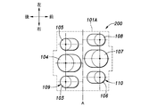
- the internal combustion engine 200 according to the third embodiment is different from the first cylinder group 109 in the internal combustion engine 100 according to the second embodiment described above in that the second cylinder group 110 is connected to the axis of the crankshaft 111. It has a form offset to the left side along the A direction.
- the center of the third combustion cylinder 106 is located between the center of the first combustion cylinder 103 and the center of the supercharging cylinder 104 in the direction of the axis A of the crankshaft 201, and the expansion.
- the center of the cylinder 107 is located between the center of the supercharging cylinder 104 and the center of the second combustion cylinder 105, and the center of the fourth combustion cylinder 108 is the side opposite to the supercharging cylinder 104 side than the center of the second cylinder. (Left side).
- the configuration of the crankshaft 201 corresponds to the configuration of the crankshaft 111 of the internal combustion engine 100 according to the second embodiment, corresponding to the arrangement of the first and second cylinder groups 109 and 110. Different.
- the description of the same configuration as in the second embodiment is omitted.
- the crankshaft 201 of the internal combustion engine 200 includes a first journal 202A, a right first arm 203AR, a first crankpin 204A, a second crankpin 204B, Left first arm 203AL, second journal 202B, right second arm 203BR, third crankpin 204C, fourth crankpin 204D, left second arm 203BL, third journal 202C, right third arm 203CR, fifth crankpin 204E, a sixth crank pin 204F, a left third arm 203CL, and a fourth journal 202D.
- the first crankpin 204A and the second crankpin 204B may be directly connected or may be connected via a crank arm (web) therebetween.
- crankpin 204C and the fourth crankpin 204D may be directly connected or may be connected via a crank arm (web) therebetween.
- the fifth crankpin 204E and the sixth crankpin 204F may be directly connected or may be connected via a crank arm (web) therebetween.
- the first crankpin 204A and the second crankpin 204B have at least a part of the overlap as viewed from the direction of the axis A of the crankshaft 201.
- the third crankpin 204C and the fourth crankpin 204D overlap at least partially when viewed from the direction of the axis A of the crankshaft 201.
- the fifth crankpin 204E and the sixth crankpin 204F preferably overlap each other at least partially. According to this configuration, the rigidity of the crankshaft 201 is improved.
- the first crank pin 204A is connected to the first combustion piston 103A via a connecting rod
- the second crank pin 204B is connected to the third combustion piston 106A via a connecting rod
- the third crank pin 204C is supercharged via the connecting rod.
- the fourth crankpin 204D is connected to the expansion piston 107A via a connecting rod
- the fifth crankpin 204E is connected to the second combustion piston 105A via a connecting rod
- the sixth crankpin 204F is connected to the piston 104A.
- the first crank pin 204A and the fifth crank pin 204E are arranged in the same phase.
- the third crank pin 204C is arranged so that the supercharging piston 104A is located at the top dead center when the first combustion piston 103A is located at the bottom dead center.
- the third crank pin 204C may be retarded so that the supercharging piston 104A is positioned before the top dead center when the first combustion piston 103A is positioned at the bottom dead center.
- the second crankpin 204B and the sixth crankpin 204F are arranged in the same phase.
- the second crank pin 204B is arranged so that the third combustion piston 106A is located at the top dead center when the first combustion piston 103A is located at the top dead center.
- the fourth crank pin 204D is arranged so that the expansion piston 107A is located at the top dead center when the second combustion piston 105A is located at the bottom dead center.
- the fourth crank pin 204D may be advanced so that the expansion piston 107A is at a position past the top dead center when the third combustion piston 106A is located at the bottom dead center.
- the second combustion cylinder 105 and the third combustion cylinder 106 are spaced apart by 360 °. And the other of the fourth combustion cylinders 108 explode simultaneously.
- the position of the supercharging cylinder 104 may be offset to the retard side with respect to the first combustion cylinder 103. Further, the position of the expansion cylinder 107 may be offset toward the advance side with respect to the third combustion cylinder 106.
- the arrangement of the first cylinder group 109 and the second cylinder group 110 may be V type or parallel arrangement.
- a modification of a part of the configuration of the internal combustion engine 200 of the third embodiment is referred to as an internal combustion engine 300 according to a modification of the third embodiment.
- the internal combustion engine 300 differs from the internal combustion engine 200 in the configuration of the crankshaft 301. Further, the position of the supercharging cylinder 104 is offset toward the retard side with respect to the first combustion cylinder 103, and the position of the expansion cylinder 107 is offset toward the advance side with respect to the third combustion cylinder 106. Other configurations of the internal combustion engine 300 are the same as those of the internal combustion engine 200.
- the first journal 302A, the right first arm 303AR, the first crankpin 304A, the left first arm 303AL, the second journal 302B, the right second arm 303BR, and the second crankpin 304B left second arm 303BL, third journal 302C, right third arm 303CR, third crankpin 304C, left third arm 303CL, fourth journal 302D, right fourth arm 303DR, fourth crankpin 304D, left first 4 arms 303DL, fifth journal 302E, right fifth arm 303ER, fifth crank pin 304E, left fifth arm 303EL, sixth journal 302F, right sixth arm 303FR, sixth crank pin 304F, left sixth arm 303FL, It has a seventh journal 302G.
- the first crank pin 304A is connected to the first combustion piston 103A via a connecting rod
- the second crank pin 304B is connected to the third combustion piston 106A via a connecting rod
- the third crank pin 304C is supercharged via the connecting rod.
- the fourth crankpin 304D is connected to the expansion piston 107A via a connecting rod
- the fifth crankpin 304E is connected to the second combustion piston 105A via a connecting rod
- the sixth crankpin 304F is connected to the piston 104A.
- the first crank pin 204A and the fifth crank pin 204E are arranged in the same phase.
- the third crank pin 204C is arranged so that the supercharging piston 104A is located at the top dead center when the first combustion piston 103A is located at the bottom dead center. Further, the third crank pin 204C may be retarded so that the supercharging piston 104A is positioned before the top dead center when the first combustion piston 103A is positioned at the bottom dead center.
- the second crankpin 204B and the sixth crankpin 204F are arranged in the same phase.
- the second crank pin 204B is arranged so that the third combustion piston 106A is located at the top dead center when the first combustion piston 103A is located at the bottom dead center.
- the fourth crank pin 204D is arranged so that the expansion piston 107A is located at the top dead center when the second combustion piston 105A is located at the bottom dead center. Further, the fourth crank pin 204D may be advanced so that the expansion piston 107A is at a position past the top dead center when the third combustion piston 106A is located at the bottom dead center.
- the internal combustion engine 300 is 180 ° in the order of one of the first combustion cylinder 103, the third combustion cylinder 106, and the fourth combustion cylinder 108, and the other of the second combustion cylinder 105, the third combustion cylinder 106, and the fourth combustion cylinder 108. Explode at intervals.
- the arrangement of the first cylinder group 109 and the second cylinder group 110 may be V type or parallel arrangement.
- the present invention is not limited to the above-described embodiment, and can be widely modified.
- the front and rear positions of the first cylinder group 109 and the second cylinder group 110 may be reversed.
- the crankshafts 201 and 301 may be arranged such that the axes thereof extend in the front-rear direction, and the first cylinder group 109 and the second cylinder group 110 may be arranged on the left and right.
Landscapes
- Engineering & Computer Science (AREA)
- Chemical & Material Sciences (AREA)
- Combustion & Propulsion (AREA)
- Mechanical Engineering (AREA)
- General Engineering & Computer Science (AREA)
- Supercharger (AREA)
- Output Control And Ontrol Of Special Type Engine (AREA)
Abstract
Le problème traité par la présente invention consiste à rendre plus compact et à améliorer l'efficacité de refroidissement d'un moteur à combustion interne ayant un cylindre de compresseur d'alimentation et un cylindre de détente. La solution selon l'invention porte sur un moteur à combustion interne (1) ayant : un corps principal (1A) de moteur à combustion interne comprenant un cylindre de compresseur d'alimentation (8) raccordé à un passage d'admission (2), un premier cylindre de combustion (6) raccordé au cylindre de compresseur d'alimentation, un second cylindre de combustion (7) raccordé au cylindre de compresseur d'alimentation et un cylindre de détente (9) raccordé aux premier et second cylindres de combustion et un passage d'échappement ; et un vilebrequin commun (11) supporté en rotation par le corps principal de moteur à combustion interne et ayant des pistons (6A, 7A, 8A, 9A) raccordés chacun à celui-ci par une bielle, lesdits pistons étant logés par le premier cylindre de combustion, le second cylindre de combustion, le cylindre de compresseur d'alimentation et le cylindre de détente, respectivement. Le cylindre de compresseur d'alimentation et le cylindre de détente sont disposés entre le premier cylindre de combustion et le second cylindre de combustion dans la direction axiale du vilebrequin.
Priority Applications (1)
| Application Number | Priority Date | Filing Date | Title |
|---|---|---|---|
| JP2017556379A JP6450475B2 (ja) | 2015-12-17 | 2016-10-03 | 内燃機関 |
Applications Claiming Priority (2)
| Application Number | Priority Date | Filing Date | Title |
|---|---|---|---|
| JP2015246549 | 2015-12-17 | ||
| JP2015-246549 | 2015-12-17 |
Publications (1)
| Publication Number | Publication Date |
|---|---|
| WO2017104231A1 true WO2017104231A1 (fr) | 2017-06-22 |
Family
ID=59056526
Family Applications (1)
| Application Number | Title | Priority Date | Filing Date |
|---|---|---|---|
| PCT/JP2016/079351 Ceased WO2017104231A1 (fr) | 2015-12-17 | 2016-10-03 | Moteur à combustion interne |
Country Status (2)
| Country | Link |
|---|---|
| JP (1) | JP6450475B2 (fr) |
| WO (1) | WO2017104231A1 (fr) |
Citations (4)
| Publication number | Priority date | Publication date | Assignee | Title |
|---|---|---|---|---|
| GB2264333A (en) * | 1992-02-06 | 1993-08-25 | Ian Nicholas Harper | Compound expansion i.c.piston engine. |
| JPH10227224A (ja) * | 1997-02-12 | 1998-08-25 | Yanmar Diesel Engine Co Ltd | 機械過給式多気筒機関 |
| JP2007127005A (ja) * | 2005-11-01 | 2007-05-24 | Toyota Central Res & Dev Lab Inc | 内燃機関 |
| WO2015090341A1 (fr) * | 2013-12-19 | 2015-06-25 | Volvo Truck Corporation | Moteur à combustion interne |
Family Cites Families (9)
| Publication number | Priority date | Publication date | Assignee | Title |
|---|---|---|---|---|
| US1634468A (en) * | 1917-07-03 | 1927-07-05 | Muller Friedrich | Four-cycle internal-combustion engine working with an injection air compressor |
| GB537424A (en) * | 1939-11-20 | 1941-06-23 | Fredrik Hurum | Improvements in and relating to internal combustion engines |
| BE1000774A5 (fr) * | 1987-07-30 | 1989-04-04 | Schmitz Gerhard | Moteur a combustion interne a six temps. |
| BE1002364A4 (fr) * | 1988-12-30 | 1991-01-15 | Schmitz Gerhard | Moteur a combustion interne a deux temps etages. |
| US5103645A (en) * | 1990-06-22 | 1992-04-14 | Thermon Manufacturing Company | Internal combustion engine and method |
| US8371256B2 (en) * | 2009-05-27 | 2013-02-12 | GM Global Technology Operations LLC | Internal combustion engine utilizing dual compression and dual expansion processes |
| US8646421B2 (en) * | 2009-10-23 | 2014-02-11 | GM Global Technology Operations LLC | Engine with internal exhaust gas recirculation and method thereof |
| US9080508B2 (en) * | 2012-11-02 | 2015-07-14 | GM Global Technology Operations LLC | Piston compound internal combustion engine with expander deactivation |
| US9334844B2 (en) * | 2013-09-27 | 2016-05-10 | Motiv Engines LLC | Reciprocating internal combustion engine |
-
2016
- 2016-10-03 WO PCT/JP2016/079351 patent/WO2017104231A1/fr not_active Ceased
- 2016-10-03 JP JP2017556379A patent/JP6450475B2/ja not_active Expired - Fee Related
Patent Citations (4)
| Publication number | Priority date | Publication date | Assignee | Title |
|---|---|---|---|---|
| GB2264333A (en) * | 1992-02-06 | 1993-08-25 | Ian Nicholas Harper | Compound expansion i.c.piston engine. |
| JPH10227224A (ja) * | 1997-02-12 | 1998-08-25 | Yanmar Diesel Engine Co Ltd | 機械過給式多気筒機関 |
| JP2007127005A (ja) * | 2005-11-01 | 2007-05-24 | Toyota Central Res & Dev Lab Inc | 内燃機関 |
| WO2015090341A1 (fr) * | 2013-12-19 | 2015-06-25 | Volvo Truck Corporation | Moteur à combustion interne |
Also Published As
| Publication number | Publication date |
|---|---|
| JP6450475B2 (ja) | 2019-01-09 |
| JPWO2017104231A1 (ja) | 2018-05-10 |
Similar Documents
| Publication | Publication Date | Title |
|---|---|---|
| US6698405B2 (en) | Reciprocating internal combustion engine with balancing and supercharging | |
| CN103547789A (zh) | 用于内燃发动机的曲轴 | |
| CN104185728B (zh) | 量调节的四冲程往复活塞式内燃机和用于运行四冲程往复活塞式内燃机的方法 | |
| US6640543B1 (en) | Internal combustion engine having variable displacement | |
| JP2010502897A (ja) | 外部熱源を備えた熱機関 | |
| RU2638901C2 (ru) | Двигатель внутреннего сгорания с наддувом и способ работы двигателя внутреннего сгорания с наддувом | |
| KR20130111560A (ko) | 스플릿-사이클 공기 하이브리드 v-엔진 | |
| CN204061515U (zh) | 用于四缸内燃机的曲轴以及四缸内燃机 | |
| CN103061899A (zh) | 内燃发动机及用于这种内燃发动机的进气交换方法 | |
| US8511265B2 (en) | Variable stroke and compression ratio engine | |
| CN106246343A (zh) | 单轴双膨胀内燃机 | |
| CN105840307B (zh) | 单轴双膨胀内燃发动机 | |
| JP2023529251A (ja) | 湿潤アルコールを燃料として使用し且つ高温支援着火を含むエンジン及びパワートレイン用の均一予混合圧縮着火式(hcci-type)燃焼システム | |
| CN100549386C (zh) | 窄角v型发动机 | |
| JP2820793B2 (ja) | ポンプシリンダと動力シリンダを備えたレシプロエンジン | |
| CN103244547B (zh) | 用于内燃发动机的曲轴 | |
| JP6450474B2 (ja) | 内燃機関 | |
| CN105840305A (zh) | 单轴双膨胀式内燃机 | |
| WO2005019619A1 (fr) | Moteur a combustion interne et cycle de fonctionnement ameliores | |
| JP6450475B2 (ja) | 内燃機関 | |
| US7762219B2 (en) | Recirculation system for motor | |
| US7739998B2 (en) | Engine having axially opposed cylinders | |
| RU2327048C1 (ru) | Двигатель внутреннего сгорания | |
| RU2521704C1 (ru) | Комбинированный поршневой двигатель | |
| CA2339315A1 (fr) | Moteur a combustion a cycles combines 2 temps - 4 temps en configuration delta |
Legal Events
| Date | Code | Title | Description |
|---|---|---|---|
| 121 | Ep: the epo has been informed by wipo that ep was designated in this application |
Ref document number: 16875216 Country of ref document: EP Kind code of ref document: A1 |
|
| ENP | Entry into the national phase |
Ref document number: 2017556379 Country of ref document: JP Kind code of ref document: A |
|
| NENP | Non-entry into the national phase |
Ref country code: DE |
|
| 122 | Ep: pct application non-entry in european phase |
Ref document number: 16875216 Country of ref document: EP Kind code of ref document: A1 |