WO2017104718A1 - Corps stratifié articulé, feuille de disposition pour corps stratifié articulé, et procédé de fabrication d'un corps stratifié articulé - Google Patents
Corps stratifié articulé, feuille de disposition pour corps stratifié articulé, et procédé de fabrication d'un corps stratifié articulé Download PDFInfo
- Publication number
- WO2017104718A1 WO2017104718A1 PCT/JP2016/087269 JP2016087269W WO2017104718A1 WO 2017104718 A1 WO2017104718 A1 WO 2017104718A1 JP 2016087269 W JP2016087269 W JP 2016087269W WO 2017104718 A1 WO2017104718 A1 WO 2017104718A1
- Authority
- WO
- WIPO (PCT)
- Prior art keywords
- layer
- hinge
- laminated body
- sheet
- hinges
- Prior art date
- Legal status (The legal status is an assumption and is not a legal conclusion. Google has not performed a legal analysis and makes no representation as to the accuracy of the status listed.)
- Ceased
Links
Images


























Classifications
-
- B—PERFORMING OPERATIONS; TRANSPORTING
- B42—BOOKBINDING; ALBUMS; FILES; SPECIAL PRINTED MATTER
- B42D—BOOKS; BOOK COVERS; LOOSE LEAVES; PRINTED MATTER CHARACTERISED BY IDENTIFICATION OR SECURITY FEATURES; PRINTED MATTER OF SPECIAL FORMAT OR STYLE NOT OTHERWISE PROVIDED FOR; DEVICES FOR USE THEREWITH AND NOT OTHERWISE PROVIDED FOR; MOVABLE-STRIP WRITING OR READING APPARATUS
- B42D1/00—Books or other bound products
- B42D1/003—Books or other bound products characterised by shape or material of the sheets
- B42D1/007—Sheets or sheet blocks combined with other articles
-
- B—PERFORMING OPERATIONS; TRANSPORTING
- B42—BOOKBINDING; ALBUMS; FILES; SPECIAL PRINTED MATTER
- B42D—BOOKS; BOOK COVERS; LOOSE LEAVES; PRINTED MATTER CHARACTERISED BY IDENTIFICATION OR SECURITY FEATURES; PRINTED MATTER OF SPECIAL FORMAT OR STYLE NOT OTHERWISE PROVIDED FOR; DEVICES FOR USE THEREWITH AND NOT OTHERWISE PROVIDED FOR; MOVABLE-STRIP WRITING OR READING APPARATUS
- B42D1/00—Books or other bound products
-
- B—PERFORMING OPERATIONS; TRANSPORTING
- B42—BOOKBINDING; ALBUMS; FILES; SPECIAL PRINTED MATTER
- B42D—BOOKS; BOOK COVERS; LOOSE LEAVES; PRINTED MATTER CHARACTERISED BY IDENTIFICATION OR SECURITY FEATURES; PRINTED MATTER OF SPECIAL FORMAT OR STYLE NOT OTHERWISE PROVIDED FOR; DEVICES FOR USE THEREWITH AND NOT OTHERWISE PROVIDED FOR; MOVABLE-STRIP WRITING OR READING APPARATUS
- B42D25/00—Information-bearing cards or sheet-like structures characterised by identification or security features; Manufacture thereof
- B42D25/20—Information-bearing cards or sheet-like structures characterised by identification or security features; Manufacture thereof characterised by a particular use or purpose
- B42D25/24—Passports
-
- B—PERFORMING OPERATIONS; TRANSPORTING
- B42—BOOKBINDING; ALBUMS; FILES; SPECIAL PRINTED MATTER
- B42D—BOOKS; BOOK COVERS; LOOSE LEAVES; PRINTED MATTER CHARACTERISED BY IDENTIFICATION OR SECURITY FEATURES; PRINTED MATTER OF SPECIAL FORMAT OR STYLE NOT OTHERWISE PROVIDED FOR; DEVICES FOR USE THEREWITH AND NOT OTHERWISE PROVIDED FOR; MOVABLE-STRIP WRITING OR READING APPARATUS
- B42D25/00—Information-bearing cards or sheet-like structures characterised by identification or security features; Manufacture thereof
- B42D25/30—Identification or security features, e.g. for preventing forgery
- B42D25/305—Associated digital information
-
- B—PERFORMING OPERATIONS; TRANSPORTING
- B42—BOOKBINDING; ALBUMS; FILES; SPECIAL PRINTED MATTER
- B42D—BOOKS; BOOK COVERS; LOOSE LEAVES; PRINTED MATTER CHARACTERISED BY IDENTIFICATION OR SECURITY FEATURES; PRINTED MATTER OF SPECIAL FORMAT OR STYLE NOT OTHERWISE PROVIDED FOR; DEVICES FOR USE THEREWITH AND NOT OTHERWISE PROVIDED FOR; MOVABLE-STRIP WRITING OR READING APPARATUS
- B42D25/00—Information-bearing cards or sheet-like structures characterised by identification or security features; Manufacture thereof
- B42D25/40—Manufacture
-
- B—PERFORMING OPERATIONS; TRANSPORTING
- B42—BOOKBINDING; ALBUMS; FILES; SPECIAL PRINTED MATTER
- B42D—BOOKS; BOOK COVERS; LOOSE LEAVES; PRINTED MATTER CHARACTERISED BY IDENTIFICATION OR SECURITY FEATURES; PRINTED MATTER OF SPECIAL FORMAT OR STYLE NOT OTHERWISE PROVIDED FOR; DEVICES FOR USE THEREWITH AND NOT OTHERWISE PROVIDED FOR; MOVABLE-STRIP WRITING OR READING APPARATUS
- B42D25/00—Information-bearing cards or sheet-like structures characterised by identification or security features; Manufacture thereof
- B42D25/40—Manufacture
- B42D25/45—Associating two or more layers
- B42D25/455—Associating two or more layers using heat
-
- B—PERFORMING OPERATIONS; TRANSPORTING
- B42—BOOKBINDING; ALBUMS; FILES; SPECIAL PRINTED MATTER
- B42D—BOOKS; BOOK COVERS; LOOSE LEAVES; PRINTED MATTER CHARACTERISED BY IDENTIFICATION OR SECURITY FEATURES; PRINTED MATTER OF SPECIAL FORMAT OR STYLE NOT OTHERWISE PROVIDED FOR; DEVICES FOR USE THEREWITH AND NOT OTHERWISE PROVIDED FOR; MOVABLE-STRIP WRITING OR READING APPARATUS
- B42D25/00—Information-bearing cards or sheet-like structures characterised by identification or security features; Manufacture thereof
- B42D25/40—Manufacture
- B42D25/45—Associating two or more layers
- B42D25/46—Associating two or more layers using pressure
-
- B—PERFORMING OPERATIONS; TRANSPORTING
- B42—BOOKBINDING; ALBUMS; FILES; SPECIAL PRINTED MATTER
- B42D—BOOKS; BOOK COVERS; LOOSE LEAVES; PRINTED MATTER CHARACTERISED BY IDENTIFICATION OR SECURITY FEATURES; PRINTED MATTER OF SPECIAL FORMAT OR STYLE NOT OTHERWISE PROVIDED FOR; DEVICES FOR USE THEREWITH AND NOT OTHERWISE PROVIDED FOR; MOVABLE-STRIP WRITING OR READING APPARATUS
- B42D25/00—Information-bearing cards or sheet-like structures characterised by identification or security features; Manufacture thereof
- B42D25/40—Manufacture
- B42D25/475—Cutting cards
-
- G—PHYSICS
- G06—COMPUTING OR CALCULATING; COUNTING
- G06K—GRAPHICAL DATA READING; PRESENTATION OF DATA; RECORD CARRIERS; HANDLING RECORD CARRIERS
- G06K19/00—Record carriers for use with machines and with at least a part designed to carry digital markings
- G06K19/02—Record carriers for use with machines and with at least a part designed to carry digital markings characterised by the selection of materials, e.g. to avoid wear during transport through the machine
-
- G—PHYSICS
- G06—COMPUTING OR CALCULATING; COUNTING
- G06K—GRAPHICAL DATA READING; PRESENTATION OF DATA; RECORD CARRIERS; HANDLING RECORD CARRIERS
- G06K19/00—Record carriers for use with machines and with at least a part designed to carry digital markings
- G06K19/06—Record carriers for use with machines and with at least a part designed to carry digital markings characterised by the kind of the digital marking, e.g. shape, nature, code
- G06K19/067—Record carriers with conductive marks, printed circuits or semiconductor circuit elements, e.g. credit or identity cards also with resonating or responding marks without active components
- G06K19/07—Record carriers with conductive marks, printed circuits or semiconductor circuit elements, e.g. credit or identity cards also with resonating or responding marks without active components with integrated circuit chips
- G06K19/0723—Record carriers with conductive marks, printed circuits or semiconductor circuit elements, e.g. credit or identity cards also with resonating or responding marks without active components with integrated circuit chips the record carrier comprising an arrangement for non-contact communication, e.g. wireless communication circuits on transponder cards, non-contact smart cards or RFIDs
-
- G—PHYSICS
- G06—COMPUTING OR CALCULATING; COUNTING
- G06K—GRAPHICAL DATA READING; PRESENTATION OF DATA; RECORD CARRIERS; HANDLING RECORD CARRIERS
- G06K19/00—Record carriers for use with machines and with at least a part designed to carry digital markings
- G06K19/06—Record carriers for use with machines and with at least a part designed to carry digital markings characterised by the kind of the digital marking, e.g. shape, nature, code
- G06K19/067—Record carriers with conductive marks, printed circuits or semiconductor circuit elements, e.g. credit or identity cards also with resonating or responding marks without active components
- G06K19/07—Record carriers with conductive marks, printed circuits or semiconductor circuit elements, e.g. credit or identity cards also with resonating or responding marks without active components with integrated circuit chips
- G06K19/077—Constructional details, e.g. mounting of circuits in the carrier
-
- B—PERFORMING OPERATIONS; TRANSPORTING
- B42—BOOKBINDING; ALBUMS; FILES; SPECIAL PRINTED MATTER
- B42D—BOOKS; BOOK COVERS; LOOSE LEAVES; PRINTED MATTER CHARACTERISED BY IDENTIFICATION OR SECURITY FEATURES; PRINTED MATTER OF SPECIAL FORMAT OR STYLE NOT OTHERWISE PROVIDED FOR; DEVICES FOR USE THEREWITH AND NOT OTHERWISE PROVIDED FOR; MOVABLE-STRIP WRITING OR READING APPARATUS
- B42D25/00—Information-bearing cards or sheet-like structures characterised by identification or security features; Manufacture thereof
- B42D25/30—Identification or security features, e.g. for preventing forgery
- B42D25/328—Diffraction gratings; Holograms
Definitions
- the present invention relates to a laminated body with hinges, a laminated body array with hinges bound to a booklet, and a manufacturing method of the laminated body with hinges.
- the first object of the present invention is to provide a hinged laminate and a hinged laminate arrangement sheet having a small thickness.
- the second object of the present invention is to provide a laminate arrangement sheet with hinges that is easy to manufacture and a method for producing a laminate with hinges.
- the present invention solves the problems by the following means.
- symbol corresponding to embodiment of this invention is attached
- the configuration described with reference numerals may be improved as appropriate, or at least a part thereof may be replaced with another configuration.
- the invention 1-1 comprises an IC module (30) having an IC chip capable of non-contact communication and a hinge layer (41, 241, 541, 641) having a hinge portion (41a) that can be bound to a booklet. And a non-hinge layer (42, 242, 542, 642) that is laminated on the hinge layer and does not have a hinge portion, wherein the hinge layer is an entire surface of the hinged laminate.
- the hinge layer and the non-hinge layer have a receiving hole (47, 247, 547, 647) penetrating over both, and the IC module is received and held in the receiving hole.
- the IC module further includes a mounting substrate (31) on which the IC chip (32) is mounted on one surface, In cross-sectional view, the width of the mounting substrate is larger than the width of the IC chip.
- the accommodation hole includes the first accommodation hole (47a) on the hinge layer side and the non-hinge layer side. The first accommodation hole accommodates one of the mounting substrate and the IC chip, and the second accommodation hole includes the mounting substrate and the IC chip. It is a laminated body with a hinge characterized by accommodating the other of these.
- the first accommodation hole or the second accommodation hole that accommodates the IC chip has a size that cannot accommodate the mounting substrate. It is a laminated body with a hinge characterized by having the width
- the 1-4th invention is characterized in that, in the hinged laminate according to any of the 1-1-1 to 1-3, the melting temperature of the hinge layer is different from the melting temperature of the non-hinge layer. It is a laminated body with a hinge.
- the 1-5th invention further includes an antenna (35) connected to the IC chip in the hinged laminated body of any of the 1-1-1st invention, wherein the hinge layer and the non-rotating body are provided.
- One or both of the hinge layers is a laminated body with hinges characterized in that it includes antenna embedding grooves (48, 248, 548, 648) for embedding the antenna.
- the 1-6th aspect of the present invention is the hinged laminated body according to any one of the first to 1-5th aspects, wherein an upper layer (50) laminated above the hinge layer and the non-hinge layer; A hinged laminate, further comprising a lower layer (60) laminated below the hinge layer and the non-hinge layer.
- the 1-7th invention is the hinged laminate according to the 1-6th invention, wherein the hinge layer and the non-hinge layer have translucency, and the upper layer comprises the hinge layer and the non-hinge layer.
- the upper layer window part (56) which can visually recognize a part of the layer near the upper layer in the hinge layer is provided, and the lower layer is a layer closer to the lower layer in the hinge layer and the non-hinge layer.
- the 1-8th invention is a hinged laminate arrangement sheet in which a plurality of hinged laminates according to any one of the 1-1 to 1-7 inventions are arranged.
- the 1-9th invention is a booklet in which the hinged laminate of any of the 1-1 to 1-7 inventions is bound by the hinge portion provided in the hinged laminate.
- the invention 2-1 includes an IC module (1030) having an IC chip capable of non-contact communication, an antenna (1035) connected to the IC chip, and a hinge portion (1041a) capable of binding to a booklet.
- a hinged laminate having a hinge layer (1041, 1241, 1341, 1441, 1541), wherein the hinge layer is formed when the upper surface of the hinged laminate is viewed from a normal direction.
- Laminated on a part of the laminated body with hinges, laminated at the same position as the hinge layer in the thickness direction, has a thickness corresponding to the hinge layer, and holds at least one of the IC module and the antenna It is a laminated body with a hinge characterized by providing a thickness adjustment layer (1042,1242,1342,1442,1542).
- the thickness adjusting layer (1042, 1242, 1542) is accommodated by accommodating the IC module (1030). (1047) forming at least a part of the laminated body with hinges.
- the 2-3rd invention is the laminated body with hinges of the 2nd-1 invention, comprising housing holes (1347, 1447) for housing the IC module (1030), and the thickness adjusting layers (1342, 1442). These are the laminated bodies with hinges characterized by covering the opening of the said accommodation hole.
- the invention of No. 2-4 includes an antenna burying layer (1043) having an antenna embedding groove (1048) in which the antenna (1035) is embedded in the hinged laminate of the invention of 2-1 or 2-3.
- the thickness adjusting layer (1042) is a laminated body with a hinge, wherein the antenna is held by covering an opening of the antenna embedding groove of the antenna embedding layer.
- the thickness adjusting layer (1242, 1542) is embedded in the antenna (1035). It is a laminated body with a hinge characterized by providing the antenna embedding groove
- the laminated body with hinges in the laminated body with hinges according to any one of the 2-1st to 2-5th inventions, is laminated on the upper side.
- the hinged laminate further includes an upper layer (1050) and a lower layer (1060) laminated on the lower side of the hinged laminate.
- the 2-7th invention is the hinged laminate of the 2-6th invention, wherein the hinge layer (1041, 1241, 1341, 1441, 1541) and / or the thickness adjusting layer (1042, 1242, 1342, 1442 and 1542) have translucency, and the upper layer (1050) includes an upper layer window (1056) through which a part of the hinge layer and the thickness adjusting layer can be visually recognized, and the lower layer (1060).
- the upper layer (1050) includes an upper layer window (1056) through which a part of the hinge layer and the thickness adjusting layer can be visually recognized, and the lower layer (1060).
- the 2-8th invention is a hinged laminate arrangement sheet in which a plurality of hinged laminates (1020, 1220, 1320, 1420, 1520) of any of the inventions 2-1 to 2-7 are arranged. is there.
- a hinged laminate (1020, 1220, 1320, 1420, 1520) according to any one of the 2-1 to the 2-5th invention, wherein the hinge part includes the hinged laminate.
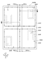
- the invention of 3-1 is a hinged laminate arrangement sheet (2020A, 2220A) in which a plurality of hinged laminates (2020, 2220) are arranged, and the hinged laminate can communicate without contact.
- a hinge according to the 3-2 invention is characterized in that the hinge portion (2041a, 2241a) protrudes on the side surface on the side to be bound in the laminated sheet with hinges of the invention 3-1. It is a laminated body arrangement
- the 3-3 invention is the hinged laminate arrangement sheet of the 3-1 or 3-2 invention, wherein the adjacent laminates with hinges (2020-1 and 2020-2, 2020-3 and 2020- 4, 2220), the hinge portions (2041a, 2241a) are arranged along at least one side of the hinged laminate arrangement sheet (2020A, 2220A). It is a body arrangement sheet.
- the hinged laminate arrangement sheet according to any one of the items 3-1 to 3-3, wherein the adjacent laminates with hinges (2020-1 and 2020-3, 2020-2). And 2020-4, 2220), the hinge portions (2041a, 2241a) are arranged on opposite sides of the hinged laminate arrangement sheet (2020A, 2220A). It is a body arrangement sheet.
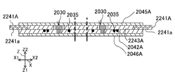
- a 3-5th invention is a hinge-arranged sheet according to any one of the 3-1 to 3-4, wherein the hinge layers of the plurality of the laminates with hinges (2220) are arranged.
- the layered sheet material (2241A) is a laminated sheet with hinges characterized in that it is laminated only on the edge of the side along the side surface from which the hinge part (2241a) protrudes.
- the hinge layers (2041) of the plurality of hinged laminates (2020) are arranged.
- the hinge layer sheet material (2041A) is larger than the outer shape of the other sheet materials (2042A, 2045A, 2046A) of the hinged laminate arrangement sheet (2020A), and the entire surface of the hinged laminate arrangement sheet. It is the laminated body arrangement
- each of the hinge portions (2241a) of the adjacent laminated body with hinges (2220) is The hinge layer sheet material (2241A) arranged along at least one side of the laminated body array sheet with hinges (2220A) and arranged with the hinge layers of the adjacent laminated body with hinges extends along the at least one side.
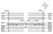
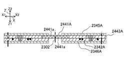
- a third to eighth invention is a hinged laminate arrangement sheet (2320A, 2420A) in which a plurality of hinged laminates (2320, 2420) are arranged, wherein the hinged laminate can communicate without contact
- each hinge part is arranged inside the laminated body with hinge arrangement sheet, and adjacent laminated bodies with hinges are continuously connected via the respective hinge parts. It is the laminated body arrangement
- a hinge according to the 3-9th invention is characterized in that, in the laminated array sheet with hinges of the 3-8th invention, the hinge portions (2341a, 2441a) protrude on the side surface to be bound. It is a laminated body arrangement
- the 3-10th invention is the hinged laminate arrangement sheet of the 3-8th or 3-9th invention, wherein the hinge layer (2441A) of the hinged laminate (2420) comprises the hinge portion (2441a). ) Is laminated only on the edge of the side along the protruding side surface.
- the invention of No. 3-11 is the hinge layer sheet material in which the hinge layers of the plurality of laminates with hinges (2320) are arranged in the laminate arrangement sheet with hinges of the invention of 3-8 or 3-9.
- (2341A) is larger than the outer shape of the other sheet material (2342A, 2345A, 2346A) of the laminate arrangement sheet with hinges (2320A) and is laminated on the entire surface of the laminate arrangement sheet with hinges.
- the invention of No. 3-12 is a method for producing a hinged laminate (2020, 2220, 2320, 2420) using the hinged laminate arrangement sheet of any of the inventions of 3-1 to 3-11. Then, by cutting the hinged laminate arrangement sheet (2020A, 2220A, 2320A, 2420A), the hinged laminate is separated into pieces so that the hinge portions (2041a, 2241a, 2341a, 2441a) remain. It is a manufacturing method of the laminated body with a hinge characterized by including an individual piece process.
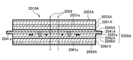
- the invention of No. 3-13 includes a laminate with hinges (2010, 2210, using the laminate arrangement sheet with hinges (2020A, 2220A, 2320A, 2420A) of any of the inventions of 3-1 to 3-11. 2310, 2410), in which an upper layer stack (2051A, 2052A, 2055A, 2351A, 2352A, 2355A) in which a plurality of lower layers are arrayed is stacked on the hinged stack array sheet.
- Steps a lower layer stacking step of stacking a lower layer array sheet in which a plurality of lower layers (2061A, 2065A, 2361A, 2365A) are arrayed on the laminate array sheet with hinges, the laminate array sheet with hinges, A hot press step of thermally welding the interlayer between the upper layer array sheet and the lower layer array sheet, and a thermally welded laminate.
- a method of manufacturing a laminated body with a hinge comprising: a single piece step of making the laminated body with a hinge into pieces so that the hinge portions (2041a, 2241a, 2341a, 2441a) remain by cutting It is.
- FIG. 1A and FIG. 1B are diagrams for explaining the configuration of a single body of the hinged laminate 10 of the first to first embodiments.
- FIG. 1A is a view of the hinged laminate 10 as viewed from the upper side Z2 in the thickness direction Z (normal direction of the upper surface).
- 1B is a cross-sectional view of the hinged laminate 10 (cross-sectional view taken along the line BB in FIG. 1A).
- FIG. 1B is a cross-sectional view through the IC module 30, but also illustrates the color development mode of the laser color generation layer 52 and the windows 56 and 66.
- FIG. 2A and 2B are diagrams for explaining the passport 1 according to the first-first embodiment.
- FIG. 2A is a perspective view of a state in which a page formed by the hinged laminate 10 is opened.
- FIG. 2B is a cross-sectional view (a cross-sectional view taken along the line BB in FIG. 2A) in a state where a page formed by the hinged laminate 10 is opened.
- an XYZ orthogonal coordinate system is provided for ease of explanation and understanding.
- This coordinate system represents the left-right direction X (left side X1, right side X2), the vertical direction Y (lower side Y1, upper side Y2), and the thickness direction Z (lower side Z1, upper side Z2) on the basis of the state of FIG. 1A. .
- the laminated body 10 with a hinge is bound to the passport 1 which is a booklet. That is, the laminated body 10 with a hinge is used for the identification item page of the passport 1 (also referred to as an IC passport or the like) incorporating the IC chip 32.
- the use of the laminated body 10 with a hinge is not limited to the passport 1, For example, you may use for management etc. of a book by binding to a book.
- the laminated body 10 with a hinge includes a laminated body 20 with a hinge, an upper layer 50, a lower layer 60, and a hologram layer 70.
- the hinged laminate 20 constitutes a part of the hinged laminate 10 including the upper layer 50, the lower layer 60, the hologram layer 70, and the like.
- the hinged laminate (with the upper layer and lower layer) is appropriately used (10 ), (No upper layer and lower layer) called a laminated body with hinges (20).
- the hinge portion 41 a of the hinged laminate 20 is bound together with other pages 6 and a cover 7 using the thread 5 and the like. As a result, the hinged laminate 10 is bound to the passport 1. Details of the hinged laminate 20 will be described later.
- the upper layer 50 is laminated on the upper side Z2 of the hinged laminate 20, and the lower layer 60 is laminated on the lower side Z1 of the hinged laminate 20.
- the hinge part 41a of the laminated body 20 with hinges protrudes from the right side surface of these layers to the right side X2.
- the upper layer 50 includes a base material layer 51, a laser coloring layer 52, a transparent protective layer 55, and an upper window portion 56. These layers are laminated in this order from the lower side Z1 to the upper side Z2.
- the base material layer 51, the laser coloring layer 52, and the transparent protective layer 55 are formed of a colorless and transparent sheet material having translucency.
- the base material layer 51 is a layer that becomes the base material of the hinged laminate 10.
- the base material layer 51 includes print layers 51a and 51c.
- the print layer 51a is printed on the upper surface of the base material layer 51 by offset printing or the like.
- the print content of the print layer 51a is a pattern or the like, for example, a character, a pattern, a symbol, or the like according to the specification of the passport 1.
- the print content of the print layer 51a is character information 51b of “PASSPORT”, “country: AAAA”, and “NAME:”.
- the print contents are common to all users. That is, this print content does not include individual information of the user (for example, the user's photograph, name, etc.).
- the print layer 51c is formed in a solid shape on the lower surface of the base material layer 51 by silk printing or the like.
- the ink of the printing layer 51c is preferably one that has high light concealing property that does not transmit light (for example, white and highly concealed ink).
- the print layers 51 a and 51 c are not provided in the region of the upper layer window portion 56. That is, the print layers 51 a and 51 c are not formed in the area of the upper layer window portion 56.
- the laser coloring layer 52 contains a coloring agent. For this reason, the range irradiated with the laser light in the laser coloring layer 52 generates heat and develops black color. In the embodiment, this color development is also called printing or printing.
- the printed content of the laser coloring layer 52 is individual information of the user. In the example of FIGS. 1A and 1B, only the information “BBB CCC” of the user's photographic image 52b and name 52c is shown, but in reality, information such as the date of birth and passport number is printed.
- the material of the laser coloring layer 52 does not need to contain a color former as long as it develops color when irradiated with laser light. The color may be other than black.
- the transparent protective layer 55 is a protective layer that protects the laser coloring layer 52.
- the upper layer window portion 56 is a rectangular portion where the print layers 51a and 51c are not provided. For this reason, when viewed from the thickness direction Z, the region in the upper window portion 56 is observed transparently.
- the lower layer 60 includes a base material layer 61, a transparent protective layer 65, and a lower layer window 66. These layers are laminated in this order from the upper side Z2 to the lower side Z1.
- the base material layer 61 and the transparent protective layer 65 are layers similar to the base material layer 51 and the transparent protective layer 55 of the upper layer 50. That is, the structure of the base material layer 61 is as follows.
- the base material layer 61 is a layer serving as a base material of the hinged laminate 10 and includes printing layers 61a and 61c.
- the print layer 61a is provided on the lower side Z1 of the base material layer 61, and the illustration of the printed content and the like is omitted, but is common to all users.
- the print layer 61c is provided on the upper side Z2 of the base material layer 61 and conceals light.
- the print layers 61 a and 61 c are not formed in the region of the lower layer window 66.
- the transparent protective layer 65 is a protective layer that protects the base material layer 61 and the printed layer 61a.
- the lower layer window portion 66 is a rectangular region in which the print layer 61a and the print layer 61c are not provided, and is viewed transparently when viewed from the thickness direction Z.
- the outer shape of the upper layer window portion 56 and the outer shape of the lower layer window portion 66 are equal and coincide with each other. Note that the present invention is not limited to this configuration, and the outer shape of one of the upper layer window portion 56 and the lower layer window portion 66 may be made slightly larger than the other shape.
- the hologram layer 70 is laminated between the hinged laminate 20 and the upper layer 50.
- the outer shape of the hologram layer 70 is slightly larger than the window portions 56 and 66 when viewed from the upper side Z2.
- the hologram layer 70 is transparent.
- a hologram image 71 such as a Lippmann hologram or an embossed hologram is recorded.
- the hologram image 71 is disposed inside the window portions 56 and 66.
- the hologram image 71 may be translucent.
- the hologram layer 70 is disposed on the lower side Z1 of the upper layer window portion 56. Therefore, when viewed from the upper side Z2, the hologram layer 70 overlaps the upper layer window portion 56 in the XY plane, but is not limited thereto. .
- the hologram layer 70 may be arranged at a position that does not overlap the upper layer window portion 56.
- the hologram layer 70 is located on the lower side Z1 than the laser coloring layer 52 and on the upper side Z2 than the laminated body 20 with hinges, but is not limited thereto.
- the hologram layer 70 may be disposed on the upper side Z2 from the laser coloring layer 52.
- the printed content of the laser coloring layer 52 of the upper layer 50 can be observed through the transparent protective layer 55.
- the printing content of the printing layer 51 a of the base material layer 51 can be observed through the laser coloring layer 52 and the transparent protective layer 55.
- the printed content of the printed layer 61 a of the base material layer 61 of the lower layer 60 can be observed through the transparent protective layer 65.
- the upper surface of the hinged laminate 20 is visible at the upper layer window portion 56.
- the lower side Z1 (opposite the observation side) of the hinged laminate 20 is observed, that is, it is observed as colorless and transparent. (See arrow L1).
- the hologram image 71 can be observed in the part where the hologram image 71 of the hologram layer 70 exists in the windows 56 and 66 (see arrow L2).
- the observation mode in the lower layer window portion 66 and the observation mode in the upper layer window portion 56 are the same.
- the hinged laminate 20 cannot be visually recognized. For this reason, since the laminated body 10 with a hinge can conceal components, such as the antenna 35, it looks good.
- the laminated body 20 with a hinge is laminated
- the laminated body 20 with the hinge includes an IC module 30, an antenna 35, a hinge layer 41, an intermediate layer 42 (antenna embedded layer) as a non-hinge layer, an upper protective layer 45, a lower protective layer 46, an IC module accommodation hole 47, and an antenna embedded.
- a groove 48 is provided.
- the lower protective layer 46, the intermediate layer 42, the hinge layer 41, and the upper protective layer 45 are laminated in this order from the lower side Z1 to the upper side Z2. These layers are joined by thermal welding. For this reason, a sheet material of a resin (for example, PET-G, PVC, PC, etc.) having a good compatibility with heat welding is used as these materials.
- the intermediate layer 42 has a single layer configuration or a multilayer configuration of a resin sheet material. The same applies to the upper protective layer 45 and the lower protective layer 46.
- the outer shapes of the intermediate layer 42, the lower protective layer 46, and the upper protective layer 45 are equal.
- the outer shape of the hinge layer 41 is larger than the outer shapes of the intermediate layer 42, the lower protective layer 46, and the upper protective layer 45. This large portion of the hinge layer 41 is a portion constituting the hinge portion 41a.
- the melting temperature of the hinge layer 41 and the melting temperature of the intermediate layer 42 may be different. If the melting temperature is different by, for example, 50 degrees or more, the resin having the lower melting temperature is likely to flow into the IC module housing hole 47 (described later) at the time of heat welding, and the clearance between the housing hole 47 and the IC module 30 is reduced. Can do.
- the relationship between the hinge layer 41 and the intermediate layer 42 and the upper layer 50 and the lower layer 60 is, for example, as follows.
- the upper layer 50 is a layer stacked above the hinge layer 41 and the intermediate layer 42.
- the lower layer 60 is a layer laminated below the hinge layer 41 and the intermediate layer 42.
- the upper layer window portion 56 can visually recognize a part of the layer close to the upper layer 50 of the hinge layer 41 and the intermediate layer 42.
- the lower layer window part 66 can visually recognize a part of the layer close to the lower layer 60 of the hinge layer 41 and the intermediate layer 42.
- the IC module 30 includes a mounting substrate 31 and an IC chip 32.
- the mounting substrate 31 is a substrate for mounting the IC chip 32.
- the mounting substrate 31 is connected to a lead frame (not shown) of the IC chip 32.
- the IC chip 32 is a semiconductor integrated circuit element, and includes a CPU (Central Processing Unit) that is a control unit and a storage device (for example, EEPROM). Identification information and the like are stored in the storage device.
- the IC chip 32 is a type that performs non-contact communication with an external device such as a reader / writer.
- the IC chip 32 is mounted on the lower surface (one surface) of the mounting substrate 31 and sealed (packaged) with resin or the like.
- the antenna 35 is obtained by winding a coated conductive wire in a coil shape (spiral shape).
- the covered conductive wire is obtained by covering the periphery of the conductive wire with a coating formed of an insulator.
- Both ends of the antenna 35 and the lead frame of the IC chip 32 are connected by an electric paste or the like. Thereby, the antenna 35 and the IC chip 32 are electrically connected.
- the connection between the IC chip 32 and the antenna 35 is not limited to the above form.
- the lead frame of the IC chip 32 and both ends of the antenna 35 may be directly connected.
- Communication between the IC module 30 and the antenna 35 and the external device is short-range wireless communication using an electromagnetic induction method (for example, communication methods using ISO / IEC14443, ISO / IEC15693, ISO / IEC18092, etc.).
- the hinge layer 41 is larger than the outer shape of the other layers 42, 45, and 46 of the hinged laminate 20. For this reason, the hinge layer 41 is provided by being laminated on the entire surface of the hinged laminate 20. “The hinge layer 41 is provided on the entire surface of the laminated body 20 with the hinge” means that the outer shape of the hinge layer 41 matches the outer shape of the laminated body 20 with the hinge. There may be a module accommodation hole 47, other windows, and openings.
- the hinge layer 41 includes a hinge portion 41a.
- the hinge part 41a is a part bound to the passport 1 (see FIG. 2B).
- the hinge part 41a protrudes from the side surface (the right side surface in FIGS. 1A and 1B) on the side that is bound to the passport 1 among the side surfaces of the hinged laminate 20. Further, the hinge layer 41 forms a part of the IC module accommodation hole 47.
- the hinge layer 41 has (i) sufficient flexibility to function as a hinge, (ii) sufficient tensile strength not to break, (iii) sufficient durability not to break even when repeatedly bent, and the like. .
- As the hinge layer 41 for example, a material in which fibers such as PET and polyamide are arranged in a lattice pattern between layers such as a plurality of resin sheets of PET-G can be used.
- the intermediate layer 42 is a layer that adjusts the thickness of the IC chip 32.
- the upper protective layer 45 is a sheet material that protects the IC module 30, the hinge layer 41, and the like by being laminated on the upper side Z ⁇ b> 2 of the hinge layer 41.
- the lower protective layer 46 is a sheet material that protects the IC module 30, the intermediate layer 42, and the like by being laminated on the lower side Z ⁇ b> 1 of the intermediate layer 42.
- the IC module accommodation hole 47 is a hole for accommodating the IC module 30.
- the IC module accommodation hole 47 is a through hole penetrating the hinge layer 41 and the intermediate layer 42.
- the hinge layer 41 and the intermediate layer 42 hold the IC module 30 by housing the IC module 30 in the IC module housing hole 47.
- the IC module housing hole 47 may be a bottomed hole.
- the width of the mounting substrate 31 is larger than the width of the IC chip 32.
- the accommodation hole 47 is divided into a first accommodation hole 47a on the hinge layer 41 side and a second accommodation hole 47b on the intermediate layer 42 side.
- the first accommodation hole 47 a accommodates one of the mounting substrate 31 and the IC chip 32.
- the second accommodation hole 47b accommodates the other of the mounting substrate 31 and the IC chip 32.
- the mounting substrate 31 is accommodated in the first accommodation hole 47a.
- the IC chip 32 is accommodated in the second accommodation hole 47b.
- it is preferable that one of the mounting substrate 31 and the IC chip 32 having a thickness close to the thickness of the hinge layer 41 is accommodated.
- the first accommodation hole 47 a or the second accommodation hole 47 b that accommodates the IC chip 32 has a width that cannot accommodate the mounting substrate 31.
- the width of the second accommodation hole 47b is smaller than the width of the mounting substrate 31, and the mounting substrate 31 cannot be accommodated in the second accommodation hole 47b.
- the antenna buried groove 48 is a groove provided on the upper surface of the intermediate layer 42.
- the antenna embedding groove 48 is formed by embedding the antenna 35 by hot pressing in a state where the antenna 35 is disposed. For this reason, when viewed from the upper side Z2, the arrangement of the antenna embedding groove 48 and the arrangement of the antenna 35 are the same.
- a hinge layer 41 is laminated immediately above the intermediate layer 42. For this reason, the intermediate layer 42 accommodates the antenna 35 in the antenna embedding groove 48, and the hinge layer 41 covers the opening of the antenna embedding groove 48. Thereby, the hinge layer 41 and the intermediate layer 42 can hold the antenna 35.
- FIG. 3A and FIG. 3B are views for explaining a hinged laminate arrangement sheet 10A according to the first-first embodiment.
- 3A is a view of the laminated body array sheet 10A with the hinges as viewed from the upper side Z2 in the thickness direction Z (normal direction of the upper surface).
- FIG. 3B is a cross-sectional view (cross-sectional view taken along the line BB of FIG. 3A) of the laminate array sheet 10A with hinges.
- the cutting part 2 that is, the outer shape of the hinged laminated body 10) cut by a press is indicated by a two-dot chain line.
- the hinged laminate arrangement sheet 10A is a sheet material in which a plurality of hinged laminates 10 are arranged. When viewed from the upper side Z2, a total of four laminated bodies 10 with hinges are arranged, two in the vertical direction Y and two in the left-right direction X. The number in the vertical direction Y can be set as appropriate according to manufacturing convenience. Moreover, in the example of FIG. 3A and FIG. 3B, although the example which provided the space 3 (margin) between the laminated bodies 10 with hinges is illustrated, this space 3 may be deleted suitably.
- the left and right hinge portions 41a protrude from the left and right side surfaces of the hinged laminate arrangement sheet 20A even in the state of the hinged laminate arrangement sheet 10A.
- the laminated configuration of the laminated body array sheet 10A with the hinge corresponds to the laminated structure of the laminated body 10 with the hinge. That is, the laminated body arrangement sheet 10A with the hinge includes the transparent protective layer sheet material 65A, the base material layer sheet material 61A, the laminated body arrangement sheet 20A with the hinge, the hologram layer 70, the base material layer sheet material 51A, and the laser coloring layer sheet material 52A.
- the transparent protective layer sheet material 55A is laminated in this order from the lower side Z1 to the upper side Z2.
- the base material layer sheet material 51A, the laser coloring layer sheet material 52A, and the transparent protective layer sheet material 55A are sheet materials (upper layer arrangement sheets) in which four members forming the upper layer 50 are arranged in the XY plane direction.
- the base material layer sheet material 51A is a sheet material in which four base material layers 51 are arranged in the XY plane direction.
- the laser color forming layer sheet material 52A and the transparent protective layer sheet material 55A are sheet materials in which four laser color forming layers 52 and transparent protective layers 55 are arranged in the XY plane direction, respectively.
- the arrangement of the four members of each sheet material corresponds to the arrangement of the four hinged laminates 20A in the hinged laminate arrangement sheet 20A (see FIGS. 4A and 4B).
- the four members forming the lower layer 60 are located at positions corresponding to the hinged laminate 20 of the hinged laminate arrangement sheet 20A. It is the sheet
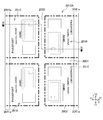
- FIG. 4A and 4B are diagrams illustrating the configuration of the hinged laminate arrangement sheet 20A according to the first to first embodiments.
- 4A is a view of the laminated body array sheet 20A with the hinges as viewed from the upper side Z2 in the thickness direction Z (the normal direction of the upper surface).
- 4B is a cross-sectional view (cross-sectional view taken along the line BB of FIG. 4A) of the laminated body array sheet 20A with hinges.
- the laminated body arrangement sheet 20A with hinges is a sheet material in which a plurality of laminated bodies 20 with hinges are arranged.
- the arrangement of the laminated body 20 with hinges in the laminated body arrangement sheet 20A with hinges is the same as that of the laminated body arrangement sheet 10A with hinges.
- a total of four laminated bodies 20 with hinges are arranged, two in the vertical direction Y and two in the left-right direction X.
- the hinge part 41a is arranged on the left side X1.
- the hinge part 41a is arranged on the right side X2.
- the two laminated bodies 20 with hinges on the left side X1 and the two laminated bodies 20 with hinges on the right side X2 are arranged symmetrically with respect to the center of the laminated body array sheet 20A with hinges.
- the number of the laminates 20 with hinges in the vertical direction Y and the space 3 can be changed in the same manner as the laminate array sheet with hinges 10A.
- hinged laminate arrangement sheet 10A having the upper layer 50 and the lower layer 60 when it is necessary to distinguish the hinged laminate arrangement sheet 10A having the upper layer 50 and the lower layer 60 from the hinged laminate arrangement sheet 20A without the upper layer 50 and the lower layer 60, respectively (there is an upper layer and a lower layer). It is called a laminated body arrangement sheet (10A) with hinges, and a laminated body arrangement sheet (20A) with hinges (without upper and lower layers).
- the laminated structure of the laminated body array sheet with hinges 20A corresponds to the laminated structure of the laminated body 20 with hinges. That is, in the laminate array sheet 20A with hinges, the lower protective layer sheet material 46A, the intermediate layer sheet material 42A, the hinge layer sheet material 41A, and the upper protective layer sheet material 45A are arranged in this order from the lower side Z1 to the upper side Z2. Are stacked.
- the hinge layer sheet material 41A is a sheet material in which four hinge layers 41 are arranged in the XY plane direction.
- the intermediate layer sheet material 42A, the upper protective layer sheet material 45A, and the lower protective layer sheet material 46A are each a sheet material in which members for four intermediate layers 42, upper protective layer 45, and lower protective layer 46 are arranged. It is.
- the arrangement of the four members of each sheet material corresponds to the arrangement of the four laminated bodies 20 with hinges of the laminated body arrangement sheet 20A with hinges.
- the left and right hinge portions 41a protrude from the left and right side surfaces of the hinged laminate arrangement sheet 20A even in the state of the hinged laminate arrangement sheet 20A.
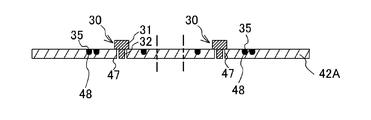
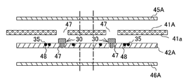
- FIG. 5A to FIG. 5D are cross-sectional views illustrating a method for manufacturing the hinged laminate array sheet 20A according to the first to first embodiments.
- Manufacturing method of laminated body arrangement sheet 20A with hinge In the case of manufacturing the laminated body array sheet 20A with hinges, the hinge layer sheet material 41A, the intermediate layer sheet material 42A, the upper protective layer sheet material 45A, and the lower protective layer sheet material 46A are manufactured in advance in the preceding process. deep. Holes are provided in the hinge layer sheet material 41A (see FIG. 5A) and the intermediate layer sheet material 42A (see FIG. 5C) by punching. The hole forms an IC module accommodation hole 47.
- the laminate array sheet with hinges 20A can be manufactured according to the following steps.
- (1) Step of forming antenna 35 As shown in FIG. 5A, the antenna 35 is embedded in the intermediate layer sheet material 42A by hot pressing in a state where the antenna 35 is arranged in a coil shape on the upper surface of the intermediate layer sheet material 42A. To do.
- the four antennas 35 may be embedded at the same time.
- the antenna 35 may be embedded in the hinge layer sheet material 41A. Also in this case, heat pressing may be performed in a state where the four antennas 35 are arranged on the hinge layer sheet material 41A.
- the hinge layer sheet material 41A, the intermediate layer sheet material 42A, the upper protective layer sheet material 45A, and the lower protective layer sheet material 46A are laminated.
- the hinge layer sheet material 41A and the intermediate layer sheet material 42A are laminated, they are aligned so that the centers of the IC module accommodation holes 47 of the two sheet materials coincide with each other.
- four hinge portions 41a of the hinge layer sheet material 41A protrude from the both ends of the intermediate layer sheet material 42A with the same length.
- the lamination process of the hinge layer sheet material 41A has good workability.
- Hot press process As shown to FIG. 5C and FIG. 5D, it heat-presses in the state which laminated
- the laminated body arrangement sheet 20A with a hinge can be manufactured by the above.
- the laminated body array sheet 10A with a hinge can be manufactured according to the following steps. (1) Lamination process of upper layer 50 (upper layer lamination process) The hologram layer 70, the base material layer sheet material 51A, the laser coloring layer sheet material 52A, and the transparent protective layer sheet material 55A are laminated on the upper side Z2 of the hinged laminate arrangement sheet 20A (see FIG. 3B).
- Lower layer 60 lamination step (lower layer lamination step) A base material layer sheet material 61A and a transparent protective layer sheet material 65A are laminated on the lower side Z1 of the laminate array sheet 20A with hinges (see FIG. 3B).
- the hinge-equipped laminate arrangement sheet 10A that is, the hinge-equipped laminate arrangement sheet 20A
- the hinge-equipped laminate arrangement sheet 20A so that the four hinge portions 41a remain
- the laminated body 10 can be manufactured.
- the laminated body 10 with a hinge can manufacture the several laminated body 10 with hinges simultaneously like the conventional card manufacture. Thereby, the laminated body 10 with a hinge can be manufactured easily, and is low-cost.
- the laminated body 10 with the hinge after being separated into pieces is processed into the passport 1 by binding the hinge portion 41a (see FIGS. 2A and 2B).
- the hinged laminated body 10 after being singulated is irradiated with laser light after being processed into the passport 1 (or before being processed), whereby individual information of the user (photograph image 52b). , Name 52c, etc.) are printed (see FIG. 1A).
- the laminate array sheet with hinges 10A is not cut, or the laminate array sheet with hinges 10A is cut into a form of a laminate array sheet with hinges to which a plurality of (for example, two) laminates with hinges 10 are connected.
- the book may be bound into a form in which a plurality of passports are arranged (so-called multiple imposition).
- the passport is separated into pieces, whereby the hinged laminate arrangement sheet 10A is separated into the hinged laminate 10.
- bookbinding can be performed in accordance with the specifications of the bookbinding machine, manufacturing convenience, and the like.
- the hinge layer 41 of this embodiment not only functions as the hinge portion 41a, but also forms a layer for holding electrical components such as the IC module 30 and the antenna 35.
- the laminated body 20 with a hinge of this embodiment is laminated
- the hinge layer 41 is provided on the entire surface of the hinged laminate 20.
- the laminated body 20 with a hinge and the laminated body 10 with a hinge can be made thin. Since the IC module 30 can be accommodated in the accommodation hole 47, it is possible to prevent the portion where the IC module 30 is provided from rising in the thickness direction. Nevertheless, the hinge portion 41a can be made thin, and the flexibility of the hinge portion 41a can be lowered.
- FIG. 6 is a cross-sectional view of the hinged laminate 210 of the first to second embodiments.
- the antenna 35 of the hinged laminate 220 of the present embodiment is embedded in the hinge layer 241.
- the hinge layer 241 includes an antenna embedding groove 248 in which the antenna 35 is embedded.
- the antenna embedding groove 248 is provided on the lower surface of the hinge layer 241.
- An intermediate layer 42 is provided immediately below the hinge layer 241. Therefore, the hinge layer 241 accommodates the antenna 35 in the antenna embedding groove 248, and the intermediate layer 42 covers the opening of the antenna embedding groove 248. Thereby, the hinge layer 241 and the intermediate layer 42 hold the antenna 35.
- the antenna embedding groove 248 of the hinge layer 241 can be formed in the same manner as the method of forming the antenna receiving groove in the intermediate layer in the 1-1 embodiment (see FIGS. 5A to 5D). That is, heat pressing may be performed in a state where the antenna 35 is disposed on the lower surface of the hinge layer sheet material.
- the hinge layer 241 of this embodiment forms a layer for holding electrical components such as the antenna 35 as in the first to first embodiments.
- the thickness of the stacked body 210 can be reduced.
- FIG. 7 is a cross-sectional view of the hinged laminate 310 of the first to third embodiments.
- the lower protective layer 46, the intermediate layer 42, the intermediate layer 349, and the hinge layer 341 are laminated in this order from the lower side Z1 to the upper side Z2. Yes. Therefore, a hinge layer 341 is laminated on the uppermost layer of the hinged laminate 320 instead of the upper protective layer.
- the intermediate layer 349 can be formed of a resin sheet material similar to the intermediate layer 42.
- the intermediate layer 349 holds the antenna 35 by covering the antenna embedding groove 48 of the intermediate layer 42 in the same manner as the hinge layer of the first to first embodiments. Further, the intermediate layer 349 and the intermediate layer 42 form an IC module accommodation hole 347 that accommodates the IC module 30.
- the hinge layer 341 Since the hinge layer 341 is stacked immediately above the intermediate layer 349, the hinge layer 341 covers the opening of the IC module accommodation hole 347. Thereby, the hinge layer 341, the intermediate layer 42, and the intermediate layer 349 can hold the IC module 30.
- the hinge layer 341 forms a layer for holding the IC module 30, so the laminated body 320 with the hinge does not need an upper protective layer. Thereby, the thickness of the laminated body 320 with a hinge and the laminated body 310 with a hinge can be made thin.
- FIG. 8 is a cross-sectional view of the hinged laminate 410 of the first to fourth embodiments.
- the hinge layer 441, the intermediate layer 42, the intermediate layer 449, and the upper protective layer 45 are stacked in this order from the lower side Z1 to the upper side Z2. ing.
- the hinge layer 441 is laminated
- the intermediate layer 449 and the intermediate layer 42 form an IC module accommodation hole 447 for accommodating the IC module 30 as in the first to third embodiments. Since the hinge layer 441 is laminated immediately below the intermediate layer 42, the hinge layer 441 covers the opening on the lower side Z1 of the IC module accommodation hole 447. Thereby, the hinge layer 441, the intermediate layer 42, and the intermediate layer 449 can hold the IC module 30.
- the laminated body with hinges 420 since the laminated body with hinges 420 according to the present embodiment does not require a lower protective layer, the laminated body with hinges 410 and the laminated body with hinges 420 are thick as in the first to third embodiments. The thickness can be reduced.
- FIG. 9 is a cross-sectional view of the hinged laminate 510 of the first to fifth embodiments.
- the lower protective layer 46, the hinge layer 541, the intermediate layer 542, and the upper protective layer 45 are laminated in this order from the lower side Z1 to the upper side Z2.
- the IC module hole 547 passes through the intermediate layer 542 and the hinge layer 541 in this order from the upper side Z2.
- the antenna embedding hole 548 is provided on the upper surface of the hinge layer 541.
- the antenna embedding hole 548 may be hot-pressed in a state where the antenna 35 is disposed on the upper surface of the hinge layer sheet material as in the first to second embodiments.
- the laminated structure of the laminated body 520 with a hinge can be changed according to a specification etc.
- FIG. 10 is a cross-sectional view of the hinged laminate 610 of the first to sixth embodiments.
- the lower protective layer 46, the hinge layer 641, the intermediate layer 642, and the upper protective layer 45 are laminated in this order from the lower side Z ⁇ b> 1 to the upper side Z ⁇ b> 2.
- the IC module hole 647 passes through the intermediate layer 642 and the hinge layer 641 in this order from the upper side Z2.
- the antenna embedding hole 648 is provided across both the upper surface of the hinge layer 641 and the lower surface of the intermediate layer 642.
- the antenna embedding hole 648 is formed when the antenna 35 is disposed on the upper surface of the hinge layer sheet material or the lower surface of the intermediate layer sheet material, and the sheet material on the opposite side is recessed by the antenna 35 if hot pressing is performed.
- the laminated structure of the laminated body 620 with a hinge can be changed according to a specification etc.
- the example in which the laminated sheet with hinges (with upper layer and lower layer) is cut to form the laminated body with hinges (with upper layer and lower layer) into pieces is not limited to this.
- the laminated body with hinges with the upper layer and lower layer
- the laminated body with the hinge can be used for management of the booklet.
- the laminated body with a hinge without an upper layer and a lower layer
- the laminated body with an upper layer and a lower layer can be used for management of the booklet.
- hinged laminate arrangement sheet without cutting the hinged laminate arrangement sheet, or (without upper layer and lower layer) with multiple (for example, two) hinged laminate arrangement sheets are connected (no upper layer and lower layer)
- it may be bound by binding in a state of being punched into a laminated sheet with hinges (no upper layer and lower layer), and may be separated into individual pieces.
- the base material layer, the laminate with hinges has translucency
- the window portion shows an example in which the base material layer is transmitted and the opposite side can be observed. It is not limited to this.
- the base material layer and the laminate with hinge may not have translucency.
- the base material layer may be a sheet material such as white having light hiding properties. In this case, by providing the window only on the upper layer, the hologram image can be observed in this window.
- the base material layer does not require a white or other solid print layer for concealing light.
- seat with a hinge showed the example by which the laminated body with a hinge was arranged in both the left-right direction and the vertical direction, it is not limited to this.
- the laminated body arrangement sheet with hinges may have a form in which the laminated bodies with hinges are arranged in one of the left-right direction and the vertical direction.
- the laminated structure of the laminated body with a hinge of embodiment can be changed suitably.
- the configuration of FIGS. 1A and 1B can be changed as follows. Without providing the printing layer 51a on the base material layer 51, a transparent layer printed with the same content as the printing layer 51a is placed under the transparent protective layer 55 (that is, between the laser coloring layer 52 and the transparent protective layer 55). You may laminate. In this case, a security film such as a hologram layer may be laminated between the laser coloring layer 52 and the printed transparent layer.
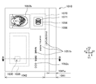
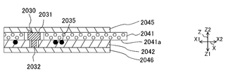
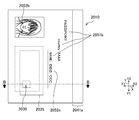
- FIG. 11A and FIG. 11B are diagrams for explaining a single structure of the hinged laminate 1010 of the 2-1 embodiment.
- FIG. 11A is a view of the laminated body 1010 with the hinge viewed from the upper side Z2 in the thickness direction Z (that is, the normal direction of the upper surface of the laminated body 1010 with the hinge and the laminated body 1020 with the hinge).
- FIG. 11B is a sectional view of the hinged laminate 1010 (a sectional view taken along the line BB in FIG. 11A).
- FIG. 11A is a view of the laminated laminate 1010 with the hinge viewed from the upper side Z2 in the thickness direction Z (that is, the normal direction of the upper surface of the laminated body 1010 with the hinge and the laminated body 1020 with the hinge).
- FIG. 11B is a sectional view of the hinged laminate 1010 (a sectional view taken along the line BB in FIG. 11A).
- FIG. 11B shows a state in which some layers are separated from each other, but in reality, all the layers are joined by thermal welding.
- FIG. 11B shows the shape of a cut surface passing through the IC module 1030. Note that the window portions 1056 and 1066, the photographic image 1052b of the laser coloring layer 1052, and the like are not located on the line BB, but these are shown in FIG. 11B for convenience. The same applies to the sectional views of the subsequent drawings.
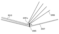
- 12A and 12B are diagrams illustrating the passport 1001.
- FIG. 12A is a perspective view of a state in which a page formed by the laminated body 1010 with hinges is opened.
- 12B is a cross-sectional view (a cross-sectional view taken along the line BB in FIG.
- an XYZ orthogonal coordinate system is provided for ease of explanation and understanding.
- This coordinate system represents the left-right direction X (left side X1, right side X2), the vertical direction Y (lower side Y1, upper side Y2), and the thickness direction Z (lower side Z1, upper side Z2) on the basis of the state of FIG. 11A. .
- the laminated body 1010 with the hinge is bound to a passport 1001 which is a booklet (see FIGS. 12A and 12B). That is, the laminated body 1010 with a hinge is used for an identification item page of a passport 1001 (also referred to as an IC passport or the like) incorporating an IC chip 1032. Note that the use of the hinged laminate 1010 is not limited to the passport 1001, and may be used for book management, for example, by binding to a book.
- the laminated body 1010 with hinge includes a laminated body 1020 with hinge (without upper layer and lower layer), an upper layer 1050, a lower layer 1060, and a hologram layer 1070.
- the hinge portion 1041a of the hinged laminate 1020 is bound together with other pages 1006 and a cover 1007 using a thread 1005 or the like.
- the hinged laminate 1010 is bound to the passport 1001.
- the hinge portion 1041a of the hinged laminated body 1020 protrudes from the right side surface of the upper layer 1050 and the lower layer 1060 to the right side X2. Details of the hinged laminate 1020 will be described later.
- the upper layer 1050 is laminated on the upper side Z2 of the hinged laminate 1020, and the lower layer 1060 is laminated on the lower side Z1 of the hinged laminate 1020.
- the upper layer 1050 includes a base material layer 1051, a laser coloring layer 1052, a transparent protective layer 1055, and an upper window portion 1056. These layers are laminated in this order from the lower side Z1 to the upper side Z2.
- the base material layer 1051, the laser coloring layer 1052, and the transparent protective layer 1055 are formed of a colorless and transparent light-transmitting sheet material.
- the base material layer 1051 is a layer that serves as a base material of the hinged laminate 1010.
- the base material layer 1051 includes printing layers 1051a and 1051c.
- the print layer 1051a is printed on the upper surface of the base material layer 1051 by offset printing or the like.
- the print content of the print layer 1051a is a pattern or the like, for example, a character, a pattern, a symbol, or the like according to the specification of the passport 1001.
- the print content of the print layer 1051a is character information 1051b of “PASSPORT”, “country: AAAA”, and “NAME:”.
- the print contents are common to all users. That is, this print content does not include individual information of the user (for example, the user's photograph, name, etc.).
- the print layer 1051c is formed in a solid shape on the lower surface of the base material layer 1051 by silk printing or the like.
- the ink for the printing layer 1051c is preferably an ink with high light hiding property that does not transmit light (for example, white and highly hiding ink).
- the print layers 1051a and 1051c are not provided in the region of the upper layer window portion 1056. That is, the print layers 1051a and 1051c are not formed in the region of the upper layer window portion 1056.
- the laser coloring layer 1052 contains a coloring agent. For this reason, the range irradiated with laser light in the laser coloring layer 1052 generates heat and develops black color. In the embodiment, this color development is also called printing or printing.
- the printed content of the laser coloring layer 1052 is individual information of the user. In the example of FIGS. 11A and 11B, only the information “BBB CCC” of the user's photographic image 1052b and name 1052c is shown, but in reality, information such as the date of birth and passport number is printed. Note that the material of the laser coloring layer 1052 may not contain a color former as long as the material develops color when irradiated with laser light. The color may be other than black.
- FIGS. 11A and 11B illustrate the state in which the hinged laminate 1010 is colored in order to explain the printing contents of the laser coloring layer 52.
- the laser coloring layer 1052 is printed in the hinged laminate 1010. May be performed after binding to the passport 1001.
- the transparent protective layer 1055 is a protective layer that protects the laser coloring layer 1052.
- the upper layer window portion 1056 is a rectangular portion where the printing layers 1051a and 1051c are not provided. When viewed from the thickness direction Z, the region in the upper window portion 1056 is observed transparently.
- the lower layer 1060 includes a base material layer 1061, a transparent protective layer 1065, and a lower layer window 1066. These layers are laminated in this order from the upper side Z2 to the lower side Z1.
- the base material layer 1061 and the transparent protective layer 1065 are layers similar to the base material layer 1051 and the transparent protective layer 1055 of the upper layer 1050. That is, the structure of the base material layer 1061 is as follows.
- the base material layer 1061 is a layer that becomes a base material of the hinged laminate 1010, and includes printing layers 1061a and 1061c.
- the print layer 1061a is provided on the lower side Z1 of the base material layer 1061. Illustration of the print contents and the like is omitted, but is common to all users.
- the printing layer 1061c is provided on the upper side Z2 of the base material layer 1061, and conceals light.
- the print layers 1061a and 1061c are not formed in the region of the lower layer window 1066.
- the transparent protective layer 1065 is a protective layer that protects the base material layer 1061 and the printed layer 1061a.
- the lower layer window portion 1066 is a rectangular region in which the print layers 1061a and 1061c are not provided, and is viewed transparently when viewed from the thickness direction Z.
- the outer shape of the upper layer window portion 1056 and the outer shape of the lower layer window portion 1066 are equal and coincide with each other. Note that the present invention is not limited to this configuration, and the outer shape of one of the upper layer window portion 1056 and the lower layer window portion 1066 may be made slightly larger than the other outer shape.
- the hologram layer 1070 is laminated between the hinged laminate 1020 and the upper layer 1050.
- the outer shape of the hologram layer 1070 is slightly larger than the window portions 1056 and 1066 when viewed from the upper side Z2.
- the hologram layer 1070 is transparent.
- a hologram image 1071 such as a Lippmann hologram or an embossed hologram is recorded.
- Hologram image 1071 is arranged inside window portions 1056 and 1066. Note that the hologram image 1071 may be translucent.
- the hologram layer 1070 is disposed on the lower side Z1 of the upper layer window portion 1056. Therefore, when viewed from the upper side Z2, the hologram layer 1070 overlaps the upper layer window portion 1056 in the XY plane. .
- the hologram layer 1070 may be arranged at a position that does not overlap the upper window portion 1056.
- the hologram layer 1070 is located on the lower side Z1 than the laser coloring layer 1052, and is located on the upper side Z2 relative to the laminated body 1020 with the hinge, but is not limited thereto.
- the hologram layer 1070 may be disposed on the upper side Z2 of the laser coloring layer 1052.
- the hologram layer 1070 on the upper side Z2 thereof is destroyed. For this reason, the tampering prevention effect can be improved.
- the printed content of the laser coloring layer 1052 of the upper layer 100 can be observed through the transparent protective layer 1055.
- the printing content of the printing layer 1051a of the base material layer 1051 can be observed through the laser coloring layer 1052 and the transparent protective layer 1055.
- the printed content of the printed layer 1061 a of the base material layer 1061 of the lower layer 1060 can be observed through the transparent protective layer 1065.
- the upper surface of the hinged laminate 1020 is visible at the upper layer window portion 1056 when observed from the upper side Z2.
- the lower side Z1 the side opposite to the observation side
- the hologram image 1071 can be observed in a portion of the window portions 1056 and 1066 where the hologram image 1071 of the hologram layer 1070 is present (see arrow L2).
- the observation mode in the lower layer window portion 1066 and the observation mode in the upper layer window portion 1056 are the same.
- the hinged laminate 1020 cannot be visually recognized. For this reason, since the laminated body 1010 with a hinge can hide components, such as the antenna 1035, it looks good.
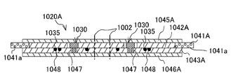
- the laminated body 1020 with hinge (without upper layer and lower layer) is laminated at substantially the center in the thickness direction Z of the laminated body 1010 with hinge (with upper layer and lower layer).
- the laminated body 1020 with the hinge includes an IC module 1030, an antenna 1035, a hinge layer 1041, a thickness adjusting layer 1042, an intermediate layer 1043 (antenna embedded layer), an upper protective layer 1045, a lower protective layer 1046, an IC module accommodating hole 1047, an antenna.
- a buried groove 1048 is provided.
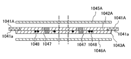
- the lower protective layer 1046, the intermediate layer 1043, the hinge layer 1041, the thickness adjusting layer 1042, and the upper protective layer 1045 are stacked in this order from the lower side Z1 to the upper side Z2. That is, the hinge layer 1041 and the thickness adjustment layer 1042 are stacked between the intermediate layer 1043 and the upper protective layer 1045 and are disposed at the same position in the thickness direction Z.
- the layers of the hinged laminate 1020 are joined by thermal welding. For this reason, a sheet material of a resin (for example, PET-G, PVC, PC, etc.) having a good compatibility with heat welding is used as these materials.
- the intermediate layer 1043 has a single layer configuration or a multilayer configuration of a resin sheet material.
- the outer shapes of the intermediate layer 1043, the lower protective layer 1046, and the upper protective layer 1045 are the same.
- the outer shape of the hinge layer 1041 and the thickness adjusting layer 1042 is larger than the outer shape of the intermediate layer 1043, the lower protective layer 1046, and the upper protective layer 1045.
- the IC module 1030 includes a mounting substrate 1031 and an IC chip 1032.
- the mounting substrate 1031 is a substrate for mounting the IC chip 1032.
- a lead frame (not shown) of the IC chip 1032 is connected to the mounting substrate 1031.
- the IC chip 1032 is a semiconductor integrated circuit element, and includes a CPU (Central Processing Unit) that is a control unit and a storage device (for example, EEPROM). Identification information and the like are stored in the storage device.
- the IC chip 1032 is a type that performs non-contact communication with an external device such as a reader / writer.
- the IC chip 1032 is mounted on the lower surface of the mounting substrate 1031 and sealed (packaged) with resin or the like.
- the antenna 1035 is obtained by winding a coated conductive wire in a coil shape (spiral shape).
- the covered conductive wire is obtained by covering the periphery of the conductive wire with a coating formed of an insulator.
- Both ends of the antenna 1035 and the lead frame of the IC chip 1032 are connected by an electric paste or the like. Thereby, the antenna 1035 and the IC chip 1032 are electrically connected.
- the connection between the IC chip 1032 and the antenna 1035 is not limited to the above mode.
- the lead frame of the IC chip 1032 and both ends of the antenna 1035 may be directly connected.
- Communication between the IC module 1030 and the antenna 1035 and an external device is short-range wireless communication using an electromagnetic induction method (for example, communication methods using ISO / IEC14443, ISO / IEC15693, ISO / IEC18092, etc.).
- the hinge layer 1041 is disposed only at the edge of the right side X2. That is, the hinge layer 1041 is disposed only at the edge in the vertical direction Y along the right side surface, which is the side surface from which the hinge portion 1041a protrudes, and is disposed over the entire edge in the vertical direction Y. For this reason, in the XY plane, the hinge layer 1041 is laminated only on part of the hinged laminate 1020.
- the hinge portion 1041a is a portion bound to the passport 1001 (see FIG. 12B).
- the hinge part 1041a protrudes from the side surface (the right side surface in FIGS. 11A and 11B) on the side bound to the passport 1001 among the side surfaces of the hinged laminate 1020.
- the hinge layer 1041 has (i) sufficient flexibility to function as a hinge, (iii) sufficient tensile strength not to break, (iii) sufficient durability to not break even when repeatedly bent, and the like.
- As the hinge layer 41 for example, a material in which fibers such as PET and polyamide are arranged in a lattice pattern between layers such as a plurality of resin sheets of PET-G can be used.
- the thickness adjustment layer 1042 is for adjusting the thickness of the hinge layer 1041. For this reason, the thickness of the thickness adjustment layer 1042 and the thickness of the hinge layer 1041 are corresponding thicknesses, that is, the same.
- the thickness adjustment layer 1042 can be formed using a material similar to that of the intermediate layer 1043. In the left-right direction X, the thickness adjustment layer 1042 and the hinge layer 1041 are in close contact, that is, they are arranged adjacent to each other so as to have almost no gap.
- the thickness adjustment layer 1042 forms a part of the IC module accommodation hole 1047.
- the laminated body 1020 with hinges can be formed flat on the upper and lower surfaces by providing the thickness adjusting layer 1042 even if the hinge layer 1041 is disposed only at the edge. Moreover, since the hinge layer 1041 of this embodiment is provided only in the edge part of the laminated body 1020 with a hinge, compared with the form provided in the whole surface, an external shape is small.
- the hinge layer 1041 is an expensive material, but the laminated body 1020 with the hinge can be manufactured at a low cost by making the hinge layer 1041 small in this way.
- the intermediate layer 1043 is a layer that adjusts the thickness of the IC chip 1032.
- the upper protective layer 1045 is a sheet material that protects the IC module 1030, the hinge layer 1041, and the like by being stacked on the upper side Z2 of the hinge layer 1041 and the thickness adjusting layer 1042.
- the lower protective layer 1046 is a sheet material that protects the IC module 1030, the intermediate layer 1043, and the like by being laminated on the lower side Z1 of the intermediate layer 43.
- the IC module accommodation hole 1047 is a hole for accommodating the IC module 1030.
- the IC module accommodation hole 1047 is a through hole that penetrates the thickness adjustment layer 1042 and the intermediate layer 1043.
- the thickness adjustment layer 1042 and the intermediate layer 1043 hold the IC module 1030 by housing the IC module 1030 in the IC module housing hole 1047.
- the IC module accommodation hole 1047 may be a bottomed hole.
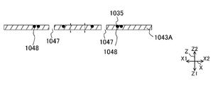
- the antenna buried groove 1048 is a groove provided on the upper surface of the intermediate layer 1043.
- the antenna embedding groove 1048 is formed by embedding the antenna 1035 by hot pressing in a state where the antenna 1035 is disposed. For this reason, when viewed from the upper side Z2, the arrangement of the antenna embedding groove 1048 and the arrangement of the antenna 1035 are the same.
- a thickness adjustment layer 1042 is stacked immediately above the intermediate layer 1043. Therefore, the intermediate layer 1043 accommodates the antenna 1035 in the antenna embedding groove 1048, and the thickness adjusting layer 1042 covers the opening of the antenna embedding groove 1048. Accordingly, the thickness adjustment layer 1042 and the intermediate layer 1043 can hold the antenna 1035.
- FIG. 13A and FIG. 13B are views for explaining the configuration of the laminated body array sheet 1010A with hinges according to the 2-1 embodiment.
- FIG. 13A is a view of the laminated body array sheet 1010A with hinges as viewed from the upper side Z2 in the thickness direction Z (the normal direction of the upper surface).
- FIG. 13B is a cross-sectional view (cross-sectional view taken along the line BB in FIG. 13A) of the laminated body array sheet 1010A with hinges.
- the cut part 2 that is, the outer shape of the laminated body 1010 with a hinge
- punched by a press is indicated by a two-dot chain line.
- the laminate array sheet 1010A with hinges is a sheet material on which a plurality of laminates 1010 with hinges (with upper layer and lower layer) are arranged.
- a total of four laminated bodies 1010 with hinges are arranged, two in the vertical direction Y and two in the left-right direction X.
- the number in the vertical direction Y can be set as appropriate according to manufacturing convenience.
- FIGS. 13A and 13B an example in which a space 1003 (margin) is provided between the hinged laminates 1010 is illustrated, but the space 1003 may be deleted as appropriate.
- the laminated structure of the laminated body array sheet with hinges 1010A corresponds to the laminated structure of the laminated body with hinges 1010. That is, the laminate array sheet 1010A with hinges (with an upper layer and lower layer) includes a transparent protective layer sheet material 1065A, a base material layer sheet material 1061A, (without an upper layer and lower layer) a laminate array sheet 1020A with hinges, a hologram layer 1070, and a base material layer.
- a sheet material 1051A, a laser coloring layer sheet material 1052A, and a transparent protective layer sheet material 1055A are laminated in this order from the lower side Z1 to the upper side Z2.
- the base material layer sheet material 1051A, the laser coloring layer sheet material 1052A, and the transparent protective layer sheet material 1055A are sheet materials (upper layer arrangement sheets) in which four members forming the upper layer 1050 are arranged in the XY plane direction. That is, the base material layer sheet material 1051A is a sheet material in which four base material layers 1051 are arranged in the XY plane direction.
- the laser coloring layer sheet material 1052A and the transparent protective layer sheet material 1055A are sheet materials in which four laser coloring layers 1052 and transparent protective layers 1055 are arranged in the XY plane direction, respectively.
- the arrangement of the four members of each sheet material corresponds to the arrangement of the four laminated bodies 1020 with hinges in the laminated body arrangement sheet 1020A with hinges (see FIGS. 14A and 14B).
- the four members forming the lower layer 1060 are placed at positions corresponding to the hinged laminate 1020 of the hinged laminate arrangement sheet 1020A. It is the sheet
- the outer shapes of the base material layer sheet materials 1051A and 1061A, the laser coloring layer sheet material 1052A, and the transparent protective layer sheet materials 1055A and 1065A are equal.
- the left and right hinge portions 1041a protrude from the left and right side surfaces of the hinged laminate arrangement sheet 1020A even in the state of the hinged laminate arrangement sheet 1010A.
- FIG. 14A and FIG. 14B are views for explaining the configuration of a laminated body array sheet 1020A with hinges according to the 2-1 embodiment.
- FIG. 14A is a view of the laminated body array sheet 1020A with the hinges as viewed from the upper side Z2 in the thickness direction Z (normal direction of the upper surface).
- FIG. 14B is a cross-sectional view (cross-sectional view taken along the line BB in FIG. 14A) of the laminate array sheet with hinges 1020A.
- the laminated body array sheet 1020A with hinges is a sheet material in which a plurality of (no upper layer and lower layer) laminated bodies 1020 with hinges are arrayed.
- the arrangement of the hinged laminate 1020A in the hinged laminate arrangement sheet 1020A is the same as that of the hinged laminate arrangement sheet 1010A.
- a total of four laminated bodies 1020 with hinges are arranged, two in the vertical direction Y and two in the left-right direction X.
- the hinge portion 1041a is arranged on the left side X1.
- the hinged laminate 1020 on the right side X2 has the hinge portion 1041a disposed on the right side X2.
- the two laminated bodies 1020 with hinges on the left side X1 and the two laminated bodies with hinges 1020 on the right side X2 are arranged point-symmetrically with respect to the center of the laminated body array sheet with hinges 1020A.
- the number of the laminated body 1020 with hinges in the vertical direction Y and the space 1003 can be changed in the same manner as the laminated body arrangement sheet 1010A with hinges.
- the left and right hinge portions 1041a protrude from the left and right side surfaces of the hinged laminate arrangement sheet 1020A even in the state of the hinged laminate arrangement sheet 1020A.
- the laminated configuration of the laminated body array sheet with hinges 1020A corresponds to the laminated structure of the laminated body with hinges 1020. That is, in the laminate array sheet with hinges 1020A, the lower protective layer sheet material 1046A, the intermediate layer sheet material 1043A, the hinge layer sheet material 1041A, the thickness adjusting layer sheet material 1042A, and the upper protective layer sheet material 1045A. The layers are stacked in this order from the lower side Z1 to the upper side Z2.
- the hinge layer sheet material 1041A is laminated on the left and right.
- the two hinge layers 1041 are in the longitudinal direction Y at positions corresponding to the arrangement of the hinged laminate arrangement sheet 1020A. It is arranged.
- the thickness adjustment layer sheet material 1042A is a sheet material in which four thickness adjustment layers 1042 are arranged at positions corresponding to the arrangement of the hinged laminate arrangement sheet 1020A.
- the thickness adjusting layer sheet material 1042A is disposed between and in close contact with the left and right hinge layer sheet materials 1041A.
- the intermediate layer sheet material 1043A, the upper protective layer sheet material 1045A, and the lower protective layer sheet material 1046A are respectively a sheet material in which members of four intermediate layers 1043, upper protective layer 1045, and lower protective layer 1046 are arranged. It is.
- FIG. 15A to FIG. 15F are cross-sectional views illustrating a method of manufacturing a hinged laminate array sheet 1020A according to the 2-1 embodiment.
- the hinge layer sheet material 1041A, the thickness adjusting layer sheet material 1042A, the intermediate layer sheet material 1043A, the upper protective layer sheet material 1045A, and the lower protection are previously prepared in the preceding process.
- a layer sheet material 1046A is manufactured in advance. Holes are provided in the thickness adjusting layer sheet material 1042A (see FIG. 15C) and the intermediate layer sheet material 1043A (see FIG. 15A), respectively, by punching.
- the hole forms an IC module accommodation hole 1047.
- the hinged laminate arrangement sheet 1020A can be manufactured according to the following steps. (1) Formation Step of Antenna 1035 As shown in FIG. 15A, the antenna 1035 is embedded in the intermediate layer sheet material 1043A by hot pressing in a state where the antenna 1035 is arranged in a coil shape on the upper surface of the intermediate layer sheet material 1043A. . As a result, an antenna embedding groove 1048 is formed on the upper surface of the intermediate layer sheet material 1043A, and the antenna 1035 is embedded therein.
- hinge layer sheet material 1041A is laminated on the left and right sides of the laminated body produced in the above steps (3).
- the alignment of the hinge layer sheet material 1041A and the thickness adjustment layer sheet material 1042A in the left-right direction X is performed by bringing the side surface of the hinge layer sheet material 1041A into contact with the side surface of the thickness adjustment layer sheet material 1042A. It is easy to do so (see arrow D).
- the example in which the thermal welding of the hinge layer sheet material 1041A and the intermediate layer sheet material 1043A is performed together with other sheet materials in the following step (5) is shown. Thus, only the hinge layer sheet material 1041A and the intermediate layer sheet material 1043A may be heat-welded.
- Hot pressing step As shown in FIGS. 15E and 15F, the upper protective layer sheet material 1045A and the lower protective layer sheet material 1046A are laminated on the laminate produced in the steps up to (4) above. , Heat press. Thereby, each interlayer is heat-welded.
- the laminated body arrangement sheet 1020A with a hinge can be manufactured by the above.
- the laminate array sheet with hinges 1010A can be manufactured according to the following steps.
- the hologram layer 1070, the base material layer sheet material 1051A, the laser coloring layer sheet material 1052A, and the transparent protective layer sheet material 1055A are laminated on the upper side Z2 of the hinged laminate arrangement sheet 1020A (see FIG. 13B).
- the hinged laminated array sheet 1010A that is, the hinged laminated array sheet 1020A
- the hinged laminated array sheet 1020A so that the four hinge parts 1041a remain
- the hinges in which the hinge parts 1041a protrude from part of the side surfaces are obtained.
- a laminated body 1010 can be manufactured.
- the laminated body 1010 with a hinge can manufacture the several laminated body 1010 with a hinge simultaneously like the conventional card manufacture. Thereby, the laminated body 1010 with a hinge can be manufactured easily, and is low-cost.
- the laminated body 1010 with hinges after being separated into pieces is processed into a passport 1001 by binding the hinge portion 1041a (see FIGS. 12A and 12B).
- the hinged laminated body 1010 after being singulated is irradiated with a laser beam after being processed into the passport 1001 (or before being processed), whereby individual information of the user (photographic image 1052b, Name 1052c etc.) are printed (see FIG. 11A).
- the hinged laminate arrangement sheet 1010A is not cut or the hinged laminate arrangement sheet 1010A is cut into a form of a hinged laminate arrangement sheet in which a plurality (for example, two) of hinged laminate arrangements 1010 are connected.
- the book may be bound into a form in which a plurality of passports are arranged (so-called multiple imposition).
- the passport is separated into pieces, whereby the hinged laminate arrangement sheet 1010A is separated into the hinged laminate 1010.
- bookbinding can be performed in accordance with the specifications of the bookbinding machine, manufacturing convenience, and the like.
- the hinge layer 1041 and the thickness adjustment layer 1042 are arranged at the same lamination position in the thickness direction Z, and the thickness adjustment layer 1042 is an electrical component. A layer for holding the film is formed. For this reason, the thickness of the laminated body 1020 with the hinge is thinner than that of a form in which a hinge layer is newly laminated on a card-like medium having electrical components. Thereby, the laminated body 1020 with a hinge and the laminated body 1010 with a hinge can be made thin.
- FIG. 16 is a cross-sectional view of the hinged laminate 1210 of the 2-2 embodiment.
- the antenna 1035 of the hinged laminate 1220 of this embodiment is embedded in the thickness adjustment layer 1242.
- the arrangement of the thickness adjusting layer 1242 and the hinge layer 1241 is the same as that in the 2-1 embodiment.
- the thickness adjustment layer 1242 includes an antenna embedding groove 1248 in which the antenna 1035 is embedded.
- the antenna embedding groove 1248 is provided on the lower surface of the thickness adjustment layer 1242.
- An intermediate layer 1043 is provided immediately below the thickness adjustment layer 1242. Therefore, the thickness adjustment layer 1242 accommodates the antenna 1035 in the antenna embedding groove 1248, and the intermediate layer 1043 covers the opening of the antenna embedding groove 1248. Accordingly, the thickness adjustment layer 1242 and the intermediate layer 1043 hold the antenna 1035.
- the antenna embedding groove 1248 of the thickness adjusting layer 1242 can be formed in the same manner as the method of forming the antenna housing groove in the intermediate layer in the 2-1 embodiment (see FIG. 15A). That is, heat pressing may be performed in a state where the antenna 1035 is disposed on the lower surface of the thickness adjustment layer sheet material.
- the thickness adjustment layer 1242 of this embodiment forms a layer for holding electrical components such as the antenna 1035, as in the case of the 2-1 embodiment.
- the hinge layer 1241 and the thickness adjustment layer 1242 are stacked at the same position. For this reason, the laminated body 1220 with a hinge and the laminated body 1210 with a hinge can be made thin.
- FIG. 17 is a cross-sectional view of the hinged laminate 1310 of the second to third embodiments.
- the laminated body with hinges 1320 of this embodiment includes a lower protective layer 1046, an intermediate layer 1043, an intermediate layer 1349, a hinge layer 1341, and a thickness adjusting layer 1342 from the lower side Z1.
- Z2 is laminated in this order. Therefore, a hinge layer 1341 and a thickness adjustment layer 1342 are laminated on the uppermost layer of the laminated body with hinges 1320 instead of the upper protective layer.
- the intermediate layer 1349 can be formed using a resin sheet material similar to that of the intermediate layer 1043.
- the intermediate layer 1349 holds the antenna 1035 by covering the antenna embedding groove 1048 of the intermediate layer 1043, similarly to the thickness adjustment layer of the 2-1 embodiment. Further, the intermediate layer 1349 and the intermediate layer 1043 form an IC module housing hole 1347 for housing the IC module 1030.
- the thickness adjustment layer 1342 Since the thickness adjustment layer 1342 is laminated immediately above the intermediate layer 1349, the thickness adjustment layer 1342 covers the opening of the IC module accommodation hole 1347. Accordingly, the thickness adjustment layer 1342, the intermediate layer 1043, and the intermediate layer 1349 can hold the IC module 1030.
- the hinge layer 1341 and the thickness adjustment layer 1342 of this embodiment are laminated on the uppermost layer of the laminated body 1320 with the hinge, and the thickness adjustment layer 1342 is a layer for holding the IC module 1030. Form. For this reason, the laminated body 1320 with a hinge does not require an upper protective layer. Accordingly, the thickness of the hinged laminate 1320 and the hinged laminate 1310 can be reduced.
- FIG. 18 is a cross-sectional view of the hinged laminate 1410 of the second to fourth embodiments.
- the laminated body with hinges 1420 of this embodiment includes a hinge layer 1441 and a thickness adjusting layer 1442, an intermediate layer 1043, an intermediate layer 1449, and an upper protective layer 1045 from the lower side Z1. It is laminated on the upper side Z2 in this order. For this reason, a hinge layer 1441 and a thickness adjusting layer 1442 are laminated in the lowermost layer of the hinged laminate 1420 instead of the lower protective layer.
- the hinge layer and the thickness adjustment layer of the second to third embodiments are laminated on the uppermost layer of the hinged laminate, whereas the hinge layer 1441 and the thickness adjustment layer 1442 of the present embodiment are It is laminated
- FIG. 1 the hinge layer and the thickness adjustment layer of the second to third embodiments are laminated on the uppermost layer of the hinged laminate, whereas the hinge layer 1441 and the thickness adjustment layer 1442 of the present embodiment are It is laminated
- the intermediate layer 1449 and the intermediate layer 1043 form an IC module accommodation hole 1447 for accommodating the IC module 1030, as in the second to third embodiments. Since the thickness adjustment layer 1442 is laminated immediately below the intermediate layer 1043, the thickness adjustment layer 1442 covers the opening on the lower side Z ⁇ b> 1 of the IC module accommodation hole 1447. Accordingly, the thickness adjustment layer 1442, the intermediate layer 1043, and the intermediate layer 1449 can hold the IC module 1030.
- the laminated body with hinges 1420 of this embodiment does not require a lower protective layer, the laminated body with hinges 1410 and the laminated body with hinges 1420 have the same thickness as in the second to third embodiments. The thickness can be reduced.
- FIG. 19 is a cross-sectional view of the hinged laminate 1510 of the second to fifth embodiments.
- the lower protective layer 1046, the hinge layer 1541 and the thickness adjusting layer 1542, the intermediate layer 1543, and the upper protective layer 1045 are provided on the lower side.
- the layers are stacked in this order from Z1 to the upper side Z2.
- the IC module accommodation hole 1047 passes through the intermediate layer 1543 and the thickness adjustment layer 1542 in this order from the upper side Z2.
- the antenna embedding groove 1048 is provided on the upper surface of the thickness adjustment layer 1542.
- the antenna embedding groove 1048 may be hot pressed in a state where the antenna 1035 is disposed on the upper surface of the thickness adjustment layer sheet material, as in the case of the 2-1 embodiment. In this manner, the stacked configuration of the hinged stacked body 1520 can be changed according to specifications and the like.
- the base material layer, the hinge layer and / or the intermediate layer (thickness adjustment layer) of the laminate with hinge have translucency, and the base material layer is transmitted through the window portion.
- the base material layer and the laminate with hinge may not have translucency.
- the base material layer may be a sheet material such as white having light hiding properties. In this case, by providing the window only on the upper layer, the hologram image can be observed in this window.
- the base material layer does not require a white or other solid print layer for concealing light.
- seat with a hinge showed the example by which the laminated body with a hinge was arranged in both the left-right direction and the vertical direction, it is not limited to this.
- the laminated body arrangement sheet with hinges may have a form in which the laminated bodies with hinges are arranged in one of the left-right direction and the vertical direction.
- the laminated structure of the laminated body with a hinge of embodiment can be changed suitably.
- the configuration of FIGS. 11A and 11B can be changed as follows.
- the base layer 1051 is not provided with the print layer 1051a, and a transparent layer printed with the same content as the print layer 1051a is placed below the transparent protective layer 1055 (that is, between the laser coloring layer 1052 and the transparent protective layer 1055).
- You may laminate.
- a security film such as a hologram layer may be laminated between the laser coloring layer 1052 and the printed transparent layer.
- FIG. 20A and FIG. 20B are views for explaining a laminated body arrangement sheet 2010A with hinges according to the 3-1 embodiment.
- FIG. 20A is a view of the laminate array sheet with hinges 2010A as viewed from the upper side Z2 in the thickness direction Z (the normal direction of the upper surface).
- 20B is a cross-sectional view (a cross-sectional view taken along the line BB in FIG. 20A) of the laminated body array sheet 2010A with a hinge.
- an XYZ orthogonal coordinate system is provided for ease of explanation and understanding.
- This coordinate system represents the left-right direction X (left side X1, right side X2), the vertical direction Y (lower side Y1, upper side Y2), and the thickness direction Z (lower side Z1, upper side Z2) on the basis of the state of FIG. 20A. . Further, in order to clearly illustrate the configuration, the configuration in the thickness direction Z is exaggerated.
- a cut portion 2002 that is, the outer shape of the hinged laminated body 2010 of punching by pressing is indicated by a two-dot chain line.
- the laminate arrangement sheet 2010A with hinges is a sheet material in which a plurality of laminates with hinges 2010 (with upper layer and lower layer) are arranged.
- the hinged laminate arrangement sheet 2010A (with upper layer and lower layer) is laminated with the hinged laminate arrangement sheet 2020A (without upper layer and lower layer), the sheet material constituting the upper layer 2050, and the sheet material constituting the lower layer 2060. It is manufactured by. Thereafter, the laminated body array sheet 2010A with hinges is cut into individual pieces of the laminated body 2010 with hinges.
- the hinged laminate 2010 includes an IC chip 2032 that stores security information.
- the hinged laminate 2010 is bound to a passport 2001 that is a booklet. That is, the laminated body with hinge 2010 is used for an identification page of a passport 2001 (also referred to as an IC passport or the like) in which an IC chip 2032 is incorporated. Note that the use of the hinged laminate 2010 is not limited to the passport 2001, and may be used for book management, for example, by binding to a book.
- FIG. 21A and FIG. 21B are diagrams for explaining a single structure of the hinged laminate 2020 of the 3-1 embodiment.
- FIG. 21A is a view of the hinged laminate 2020 as viewed from the upper side Z2 in the thickness direction Z (the normal direction of the upper surface).
- FIG. 21B is a cross-sectional view of the hinged laminate 2020 (cross-sectional view taken along the line BB in FIG. 21A).
- the laminated body 2020 with the hinge is laminated almost at the center in the thickness direction Z of the laminated body 2010 with the hinge (see FIGS. 23A and 23B).
- the hinged laminate 2020 includes an IC module 2030, an antenna 2035, a hinge layer 2041, an intermediate layer 2042, an upper protective layer 2045, and a lower protective layer 2046.
- the lower protective layer 2046, the intermediate layer 2042, the hinge layer 2041, and the upper protective layer 2045 are stacked in this order from the lower side Z1 to the upper side Z2. These layers are joined by thermal welding. For this reason, a sheet material made of a resin (for example, PET-G, PVC, etc.) having good compatibility with heat welding is used as these materials.
- the intermediate layer 2042 has a single layer configuration or a multilayer configuration of a resin sheet material. The same applies to the upper protective layer 2045 and the lower protective layer 2046.
- the outer shapes of the intermediate layer 2042, the lower protective layer 2046, and the upper protective layer 2045 are equal.
- the outer shape of the hinge layer 2041 is larger than the outer shapes of the intermediate layer 2042, the lower protective layer 2046, and the upper protective layer 2045. This large portion of the hinge layer 2041 is a portion constituting the hinge portion 2041a.
- the IC module 2030 includes a mounting substrate 2031 and an IC chip 2032.
- the mounting substrate 2031 is a substrate for mounting the IC chip 2032.
- the mounting substrate 2031 is connected to a lead frame (not shown) of the IC chip 2032.
- the IC chip 2032 is a semiconductor integrated circuit element, and includes a CPU (Central Processing Unit) that is a control unit and a storage device (for example, EEPROM). Identification information and the like are stored in the storage device.
- the IC chip 2032 is a type that performs non-contact communication with an external device such as a reader / writer.
- the IC chip 2032 is mounted on the lower surface of the mounting substrate 2031 and sealed (packaged) with resin or the like.
- the antenna 2035 is obtained by winding a coated conductive wire in a coil shape (spiral shape).
- the covered conductive wire is obtained by covering the periphery of the conductive wire with a coating formed of an insulator. Both ends of the antenna 2035 and the lead frame of the IC chip 2032 are connected by an electric paste or the like. Thereby, the antenna 2035 and the IC chip 2032 are electrically connected.
- connection between the IC chip 2032 and the antenna 2035 is not limited to the above mode.
- the lead frame of the IC chip 2032 and both ends of the antenna 2035 may be directly connected.
- Communication between the IC module 2030 and the antenna 2035 and the external device is short-range wireless communication using an electromagnetic induction method (for example, communication methods using ISO / IEC14443, ISO / IEC15693, ISO / IEC18092, etc.).
- the hinge layer 2041 is larger than the outer shape of the other layers 2042, 2045, 2046 of the hinged laminate 2020.
- the hinge layer 2041 includes a hinge portion 2041a.
- the hinge part 2041a is a part bound to the passport 2001 (see FIG. 22B).
- the hinge part 2041a protrudes from the side surface (the right side surface in FIGS. 21A and 21B) on the side bound to the passport 2001 among the side surfaces of the hinged laminate 2020.
- the hinge layer 2041 has sufficient flexibility to function as a hinge, sufficient tensile strength not to break, and sufficient durability not to break even if it is repeatedly bent.
- As the hinge layer 2041 for example, a material in which fibers such as PET and polyamide are arranged in a lattice between layers of a plurality of PET-G resin sheets or the like can be used.
- the intermediate layer 2042 is a layer that adjusts the thickness of the IC chip 2032.
- the upper protective layer 2045 is a sheet material that protects the IC module 2030, the hinge layer 2041, and the like by being laminated on the upper side Z2 of the hinge layer 2041.
- the lower protective layer 2046 is a sheet material that protects the IC module 2030, the intermediate layer 2042, and the like by being laminated on the lower side Z1 of the intermediate layer 2042.
- FIG. 22A and FIG. 22B are views for explaining the configuration of a laminated body array sheet 2020A with hinges according to the 3-1 embodiment.
- 22A is a view of the laminated body array sheet 2020A as viewed from the upper side Z2 in the thickness direction Z (normal direction of the upper surface).
- FIG. 22B is a cross-sectional view (cross-sectional view taken along the line BB in FIG. 22A) of the laminated body array sheet 2020A with a hinge.
- the laminated body array sheet 2020A with hinges is a sheet material in which a plurality of (no upper layer and lower layer) laminated bodies 2020 with hinges are arrayed.
- hinged laminate arrangement sheet 2020A When the hinged laminate arrangement sheet 2020A is viewed from the upper side Z2, four hinged laminates 2020 are arranged in total, two in the vertical direction Y and two in the left-right direction X.
- the number in the vertical direction Y can be set as appropriate according to manufacturing convenience.
- 22A and 22B illustrate an example in which a space 2003 (margin) is provided between adjacent stacked layers 2020 with hinges, the space 2003 may be deleted as appropriate.
- the hinge portion 2041a is arranged on the left side X1, while in the right-side X2 hinged laminate 2020, the hinge portion 2041a is arranged on the right side X2.
- the two laminated bodies 2020 with hinges on the left side X1 and the two laminated bodies with hinges 2020 on the right side X2 are arranged point-symmetrically.
- each hinge portion 2041a is arranged on opposite sides of the hinged laminate arrangement sheet 2020A.
- the hinge portions 2041a is arranged along the right side (at least one side) of the stacked body array sheet 2020A with hinges. Is done.
- the respective hinge portions 2041a are along the left side (at least one side) of the laminated body array sheet 2020A with hinges. Be placed.
- the laminated structure of the laminated body array sheet 2020A with the hinge corresponds to the laminated structure of the laminated body 2020 with the hinge. That is, in the laminated body array sheet 2020A with the hinge, the lower protective layer sheet material 2046A, the intermediate layer sheet material 2042A, the hinge layer sheet material 2041A, and the upper protective layer sheet material 2045A are arranged in this order from the lower side Z1 to the upper side Z2. Are stacked.
- the hinge layer sheet material 2041A is a sheet material in which four hinge layers 2041 are arranged in the XY plane direction.
- the intermediate layer sheet material 2042A, the upper protective layer sheet material 2045A, and the lower protective layer sheet material 2046A are respectively a sheet material in which members for four intermediate layers 2042, upper protective layer 2045, and lower protective layer 2046 are arranged. It is.
- the arrangement of the four members of each sheet material corresponds to the arrangement of the four hinged laminates 2020 of the hinged laminate arrangement sheet 2020A.
- the outer shapes of the intermediate layer sheet material 2042A, the upper protective layer sheet material 2045A, and the lower protective layer sheet material 2046A are equal.
- the outer shape of the hinge layer sheet material 2041A is larger than the outer shapes of the other sheet materials 2042A, 2045A, and 2046A. For this reason, the hinge layer sheet material 2041A is laminated on the entire surface of the hinged laminate arrangement sheet 2020A.
- portions larger than the other sheet materials 2042A, 2045A, and 2046A are stacked in a protruding state from the left and right side surfaces.
- the left and right protruding lengths are equal.
- the length in the longitudinal direction Y of the hinge layer sheet material 2041A is the same as the lengths of the other sheet materials 2042A, 2045A, and 2046A.
- FIG. 23A and FIG. 23B are diagrams for explaining the structure of a single unit of the hinged laminate 2010 according to the 3-1 embodiment.
- FIG. 23A is a view of the hinged laminate 2010 as viewed from the upper side Z2 in the thickness direction Z (the normal direction of the upper surface).
- FIG. 23B is a cross-sectional view of the hinged laminate 2010 (a cross-sectional view along the line BB in FIG. 23A).
- FIG. 23A and FIG. 23B illustrate a state in which the hinged laminate 2010 is colored in order to explain the printing contents of the laser coloring layer 2052.
- FIG. 23B is a cross-sectional view through the IC module 2030, but also illustrates the color development of the laser coloring layer 2052.
- the laser coloring layer 2052 may be printed after the hinged laminate 2010 is bound to the passport 1.
- FIG. 24A and 24B are diagrams for explaining a passport 2001 according to the 3-1 embodiment.
- FIG. 24A is a perspective view of a state in which a page formed by the laminated body with hinge 2010 is opened.
- 24B is a cross-sectional view (a cross-sectional view taken along line BB in FIG. 24A) in a state where a page formed by the laminated body with hinge 2010 is opened.
- the laminated body with hinge 2010 includes a laminated body with hinge 2020 (without an upper layer and lower layer), an upper layer 2050, and a lower layer 2060. As shown in FIGS. 24A and 24B, the hinge portion 2041a of the hinged laminate 2020 is bound together with other pages 2006 and a cover 2007 using a thread 2005 or the like. As a result, the hinged laminate 2010 is bound to the passport 1.
- the upper layer 2050 is laminated on the upper side Z2 of the hinged laminate 2020
- the lower layer 2060 is laminated on the lower side Z1 of the hinged laminate 2020.
- the outer shapes of the upper layer 2050 and the lower layer 2060 are equal to the outer shapes of the other sheet materials 2042A, 2045A, and 2046A of the hinged laminate 2020. For this reason, even if it is the state of the laminated body 2010 with a hinge, the hinge part 2041a of the laminated body 2020 with a hinge protrudes from the right side surface of these layers to the right side X2.
- the upper layer 2050 includes a base material layer 2051, a laser coloring layer 2052, and a transparent protective layer 2055. These layers are laminated in this order from the lower side Z1 to the upper side Z2.
- the base material layer 2051 is a layer that serves as a base material of the hinged laminate 2010.
- the color of the base material layer 2051 is preferably a high concealing property that does not transmit light (for example, white color).
- the base material layer 2051 includes a printing layer 2051a on the upper side Z2.
- the print layer 2051a is formed on the base material layer 2051 by offset printing or the like.
- the print contents of the print layer 2051a are characters, patterns, symbols, and the like according to the specifications of the passport 2001.
- the print content of the print layer 2051a is character information 2051b of “PASSPORT”, “country: AAAA”, and “NAME:”.
- the print contents are common to all users. That is, this print content does not include individual information of the user (for example, the user's photograph, name, etc.).
- the laser coloring layer 2052 has translucency and is colorless and transparent.
- the laser coloring layer 2052 contains a coloring agent. For this reason, the range irradiated with the laser beam in the laser coloring layer 2052 generates heat and develops black color. In the embodiment, this color development is also called printing or printing.
- the print contents of the laser coloring layer 2052 are individual information of the user. In the example of FIGS. 23A and 23B, only the information “BBB CCC” of the user's photographic image 2052b and name 2052c is shown, but in reality, information such as date of birth and passport number is printed.
- the transparent protective layer 2055 is a layer having translucency.
- the transparent protective layer 2055 is a protective layer that protects the laser coloring layer 2052.
- the lower layer 2060 includes a base material layer 2061 and a transparent protective layer 2065. These layers are laminated in this order from the upper side Z2 to the lower side Z1.
- the base material layer 2061 and the transparent protective layer 2065 are layers similar to the base material layer 2051 and the transparent protective layer 2055 of the upper layer 2050. That is, the base material layer 2061 is a layer that becomes the base material of the hinged laminate 2010 and has a high concealing color. Further, the base material layer 2061 includes a printing layer 2061a on the lower side Z1. Although illustration of this print content is omitted, it is common to all users.
- the transparent protective layer 2065 is a light-transmitting layer and is a protective layer that protects the base material layer 2061 and the printed layer 2061a.
- the printed content of the laser coloring layer 2052 of the upper layer 2050 can be observed through the transparent protective layer 2055.
- the printing content of the printing layer 2051a of the base material layer 2051 can be observed through the laser coloring layer 2052 and the transparent protective layer 2055.
- the printed content of the printed layer 2061a of the base material layer 2061 of the lower layer 2060 can be observed through the transparent protective layer 2065.
- the hinged laminate 2020 cannot be visually recognized. For this reason, since the laminated body 2010 with a hinge can conceal parts, such as the antenna 2035, it looks good.
- FIG. 25A to FIG. 25E are cross-sectional views illustrating a method of manufacturing the laminated body array sheet with hinges 2020A and the laminated body array sheet with hinges 2010A according to Embodiment 3-1.
- Manufacturing method of laminate arrangement sheet 2020A with hinge When manufacturing the laminated body array sheet 2020A with hinges, the hinge layer sheet material 2041A, the intermediate layer sheet material 2042A, the upper protective layer sheet material 2045A, and the lower protective layer sheet material 2046A are manufactured in advance in the previous process. deep.
- the hinge layer sheet material 2041A and the intermediate layer sheet material 2042A are each provided with a hole 2033 by punching.
- the hole 2033 forms a hole for accommodating the IC module 2030.
- the hinged laminate arrangement sheet 2020A can be manufactured according to the following steps. (1) Formation Step of Antenna 2035 As shown in FIG. 25A, the antenna 2035 is embedded in the intermediate layer sheet material 2042A by hot pressing in a state where the antenna 2035 is arranged in a coil shape on the upper surface of the intermediate layer sheet material 2042A. . The four antennas 2035 may be embedded at the same time. Note that the antenna 2035 may be embedded in the hinge layer sheet material 2041A. Also in this case, heat pressing may be performed in a state where the four antennas 2035 are arranged on the hinge layer sheet material 2041A.
- a hinge layer sheet material 2041A, an intermediate layer sheet material 2042A, an upper protective layer sheet material 2045A, and a lower protective layer sheet material 2046A are laminated.
- the hinge layer sheet material 2041 ⁇ / b> A and the intermediate layer sheet material 2042 ⁇ / b> A are stacked, they are aligned so that the centers of the holes 2033 of the two sheet materials coincide. Accordingly, four hinge portions 2041a of the hinge layer sheet material 2041A protrude from the both ends of the intermediate layer sheet material 2042A with the same length.
- the stacking process of the hinge layer sheet material 2041A has good workability.
- Hot press process As shown to FIG. 25C and FIG. 25D, it heat-presses in the state which laminated
- the laminated body arrangement sheet 2020A with a hinge can be manufactured by the above.
- a laminated body arrangement sheet 2020A with a hinge (without an upper layer and a lower layer), in the preceding process, a laminated body arrangement sheet 2020A with a hinge (without an upper layer and a lower layer), base material layer sheet materials 2051A and 2061A, laser coloring A layer sheet material 2052A and transparent protective layer sheet materials 2055A and 2065A are manufactured in advance.
- base material layer sheet material 2051A, the laser coloring layer sheet material 2052A, and the transparent protective layer sheet material 2055A four members forming the upper layer 2050 correspond to the hinged laminate 2020 of the hinged laminate arrangement sheet 2020A.
- the four members forming the lower layer 2060 are positioned at positions corresponding to the hinged laminate 2020 of the hinged laminate arrangement sheet 2020A. It is the sheet
- the outer shapes of the base material layer sheet materials 2051A and 2061A, the laser coloring layer sheet material 2052A, the transparent protective layer sheet materials 2055A and 2065A, and the outer shapes of the other sheet materials 2042A, 2045A and 2046A of the hinged laminate array sheet 2020A are as follows: equal.
- the laminate array sheet with hinges 2010A can be manufactured according to the following steps.
- Upper layer 2050 laminating step upper layer laminating step
- a base material layer sheet material 2051A, a laser coloring layer sheet material 2052A, and a transparent protective layer sheet material 2055A are laminated on the upper side Z2 of the hinged laminate arrangement sheet 2020A (see FIG. 20B).
- the hinged laminate arrangement sheet 2010A that is, the hinged laminate arrangement sheet 2020A
- the hinged laminate arrangement sheet 2020A that is, the hinged laminate arrangement sheet 2020A
- the laminated body 2010 can be manufactured.
- the laminated body 2010 with a hinge can manufacture the several laminated body 2010 with a hinge simultaneously like the conventional card manufacture.
- the laminated body 2010 with a hinge can be manufactured easily and is low-cost.
- the laminated body with hinges 2010 after being separated into pieces is processed into a passport 2001 by binding the hinge part 2041a (see FIG. 24B).
- the laminated body with hinges 2010 after being singulated is irradiated with laser light after being processed into the passport 2001 (or before being processed), whereby individual information of the user (photographic image 2052b, Name 2052c and the like) are printed (see FIG. 23A).
- the hinged laminate array sheet 2010A is not cut, or the hinged laminate array sheet 2010A is cut into a form of a hinged laminate array sheet in which a plurality of (for example, two) hinged laminates 2010 are connected.
- the book may be bound into a form in which a plurality of passports are arranged (so-called multiple imposition).
- the passport is separated into pieces, whereby the hinged laminate arrangement sheet 2010A is separated into the hinged laminate 2010.
- bookbinding can be performed according to the specifications of the bookbinding machine, manufacturing convenience, and the like.
- the hinged laminate 2010 according to the present embodiment can be easily manufactured by using the hinged laminate arrangement sheet 2020A to produce the hinged laminate 2010 from which the hinge portion 2041a protrudes. Moreover, it can be manufactured at low cost.
- FIG. 26A to FIG. 26C are views for explaining a hinged laminate arrangement sheet 2220A according to the 3-2 embodiment.
- FIG. 26A is a view of the laminated body array sheet 2220A as viewed from the upper side Z2 in the thickness direction Z (normal direction of the upper surface).
- FIG. 26B is a cross-sectional view (cross-sectional view taken along the line BB in FIG. 26A) of the laminate array sheet 2220A with hinges.
- FIG. 26C is a cross-sectional view illustrating a method of manufacturing the laminated body array sheet 2220A with hinges.
- the two hinge layer sheet materials 2241A are respectively the left X1 edge (at least one edge) and the right X2 edge (at least one edge). It is arrange
- the thickness adjustment layer sheet material 2243A is laminated inside the two hinge layer sheet materials 2241A. The thickness of the thickness adjusting layer sheet material 2243A is the same as that of the hinge layer sheet material 2241A.
- the thickness adjustment layer sheet material 2243A adjusts the thickness of the hinge layer sheet material 2241A.
- the thickness adjusting layer sheet material 2243A can be formed of the same material as the intermediate layer sheet material 2042A. By providing the thickness adjusting layer sheet material 2243A, the laminated body array sheet 2220A with hinges can form the upper surface and the lower surface flat.
- the thickness adjusting layer sheet material 2243A is first laminated on the intermediate layer sheet material 2042A. Thereafter, the hinge layer sheet material 2241A and the intermediate layer sheet material 2042A are aligned so that a portion of the right side X2 hinge layer sheet material 2241A forming the hinge portion 2241a protrudes from the intermediate layer sheet material 2042A. Similarly, the hinge layer sheet material 2241A and the intermediate layer sheet material 2042A on the right side X2 are aligned. In this way, with the hinge layer sheet material 2241A aligned and laminated, the respective layers are thermally welded by the hot press step as in the case of the 3-1 embodiment (see FIGS. 25C and 25D).
- the laminated body arrangement sheet 2220A with a hinge can be manufactured by the above.
- the hinge layer sheet material 2241A is arranged only along the edge where the hinge portion 2241a is provided.
- the outer shape can be reduced.
- FIGS. 27A and 27B are views (a diagram corresponding to FIGS. 20A and 20B) for explaining the hinged laminate arrangement sheet 2310A of the third to third embodiments.
- FIG. 27A is a view of the laminate array sheet 2310A with hinges as viewed from the upper side Z2 in the thickness direction Z (the normal direction of the upper surface).
- FIG. 27B is a cross-sectional view (cross-sectional view taken along the line BB of FIG. 27A) of the laminate array sheet 2310A with hinges.
- the single-piece structure of the hinged laminate 2310 of this embodiment is the same as that of the 3-1 embodiment.
- the laminated body 2310 with hinges adjacent to each other in the left-right direction X is arranged so that the side surface from which the hinge portion 2341a protrudes is inside the laminated body arrangement sheet 2310A with hinges.
- the laminated body 2310 with hinges adjacent to each other in the left-right direction X is continuous because the hinge portions 2341a are connected to each other.
- FIG. 28A to FIG. 28C are views for explaining a hinged laminate arrangement sheet 2320A according to the third to third embodiments.
- FIG. 28A is a view of the laminate array sheet 2320A with hinges as viewed from the upper side Z2 in the thickness direction Z (normal direction of the upper surface).
- FIG. 28B is a cross-sectional view (cross-sectional view taken along the line BB in FIG. 28A) of the laminated body array sheet 2320A with hinges.
- FIG. 28C is a cross-sectional view illustrating the method of manufacturing the laminated body array sheet 2320A with hinges. As shown in FIGS.
- the hinge portions 2341a are arranged toward the inside of the laminated body arrangement sheet 2320A with hinges, and are continuous via the respective hinge portions 2341a.
- the hinge layer sheet material 2341A is larger than the outer shape of the other sheet material, and is laminated on the entire surface of the hinged laminate arrangement sheet 2320A.
- the laminated body arrangement sheet 2310A with hinges is manufactured so as to form the laminated bodies 2320 with hinges on the left and right sides as follows. In the following, portions different from the 3-1 embodiment will be mainly described.
- an intermediate layer sheet having two intermediate layers for one hinge layer sheet material 2341A (the laminate produced in (1) above) A material 2342A, an upper protective layer sheet material 2345A having two upper protective layers, and a lower protective layer sheet material 2346A having two lower protective layers are laminated.
- the right side X2 intermediate layer sheet material 2342A, the right side X2 upper protective layer sheet material 2345A, and the right side X2 below A protective layer sheet material 2346A is laminated. Then, the layers are welded by hot pressing.
- the laminated body arrangement sheet 2320A with a hinge can be manufactured by the above.
- the alignment of the hinge layer sheet material 2341A and the other sheet material is good because the left end or the right end is aligned. Even when this alignment is performed at the end on the hinge portion 2341a side, if a jig or the like that abuts the end portions of the other sheet materials 2341A, 2342A, 2345A, and 2346A is used, the operation is easy. It is.
- a sheet material 2355A, a base material layer sheet material 2361A, and a transparent protective layer sheet material 2365A are laminated. Then, the layers are welded by hot pressing. In addition, workability
- operativity is good for the alignment of each member similarly to the manufacturing method of the laminated body arrangement
- the hinged laminate array sheet 2310A heat-welded in (1) above is cut into individual pieces by cutting the outer shape of each hinged laminate 2310 by pressing (single piece process).
- the shape of the cutting portion 2302 of each hinged laminate 2310 is a quadrangle corresponding to each hinged laminate 2310.
- the hinged laminate arrangement sheet 2310A adjacent in the left-right direction X coincides with the inner cut portion 2302. For this reason, the continuous hinge part 2341a is cut
- the hinged laminate arrangement sheet 2320A of the present embodiment has the hinged laminate 2341a of the hinged laminate 2320 adjacent to each other in the left-right direction X, and is cut to thereby cut the hinged laminate 2310. Can be manufactured. For this reason, as in the case of the 3-1 embodiment, the laminated body with hinges 2310 from which the hinge portion 2341a protrudes can be easily manufactured, and the cost is low.
- FIGS. 29A to 29C are views for explaining a hinged laminate arrangement sheet 2420A according to the third to fourth embodiments.
- FIG. 29A is a view of the laminate array sheet with hinges 2420A as viewed from the upper side Z2 in the thickness direction Z (normal direction of the upper surface).
- FIG. 29B is a cross-sectional view (cross-sectional view taken along the line BB in FIG. 29A) of the laminated body array sheet 2420A with hinges.
- FIG. 29C is a cross-sectional view illustrating a method of manufacturing the laminated body array sheet 2420A with hinges.
- the hinged laminate arrangement sheet 2420A is a hinge layer sheet material (see FIG. 28B) of the hinged laminate arrangement sheet of the third to third embodiments as in the second embodiment.
- the hinge layer sheet material and the thickness adjustment layer sheet material are changed.
- the hinge layer sheet material 2441A is arranged so as to extend in the vertical direction Y in the range of the center of the left and right of the hinged laminate arrangement sheet 2420A.
- the hinge layer sheet material 2441A is disposed only at the edge of the right-side X2 side (at least one side).
- the hinge layer sheet material 2441A is arranged only at the edge of the side (at least one side) of the left side X1. And the laminated body 2420 with a hinge adjacent to the left-right direction X is continuing via each hinge part 2441a similarly to 3rd-3 embodiment.
- the laminated body arrangement sheet 2420A with hinges when manufacturing the laminated body arrangement sheet 2420A with hinges, first, in each of the left side X1 and the right side X2, the thickness adjustment layer sheet material 2443A and the intermediate layer sheet material 2342A are laminated, A stacked body in which an antenna and an IC module are formed may be manufactured. And what is necessary is just to connect the laminated body of the left side X1 and the right side X2 by laminating
- the hinged laminate arrangement sheet 2420A of the present embodiment can be manufactured at a low cost because the outer shape of the hinge layer sheet material 2441A can be reduced as in the third to second embodiments.
- the laminated body with the hinge can be used for management of the booklet.
- the laminated body with a hinge without an upper layer and a lower layer
- the laminated body with an upper layer and a lower layer can be used for management of the booklet.
- the laminated body arrangement sheet with hinges shows an example in which the laminated body with hinges is arranged in both the left-right direction and the vertical direction, but is not limited thereto.
- the laminated body arrangement sheet with hinges may have a form in which the laminated bodies with hinges are arranged in one of the left-right direction and the vertical direction.
- a security film may be laminated between the laser coloring layer 2052 and the base material layer 2051 (printing layer 2051a).
- the laminated structure of the laminated body with a hinge of embodiment can be changed suitably.
- the configuration of FIGS. 23A and 23B can be changed as follows.
- the base layer 2051 is not provided with the print layer 2051a, and a transparent layer printed with the same contents as the print layer 2051a is placed below the transparent protective layer 2055 (that is, between the laser color developing layer 2052 and the transparent protective layer 2055).
- You may laminate.
- a security film such as a hologram layer may be laminated between the laser coloring layer 2052 and the printed transparent layer.
- IC chip 1035 ... antenna 1041, 1241, 1341, 1441 ... hinge layer 1041a ... hinge part 1042, 1242, 1342, 1442, 1542 ... Thickness adjusting layer 1043, 1349, 1449, 1543 ... Intermediate layer 1045 ... Upper protective layer 1046 ... Lower protective layer 1047, 1347, 1447 ... IC module accommodation 1048, 1248 ... Antenna buried groove 1050 ... Upper layer 1051, 1061 ... Base material layer 1051a, 1051c, 1061a, 1061c ... Printed layer 1052 ... Laser coloring layer 1055, 1065 ... Transparent protective layer 1056 ... Upper layer window 1060 ... Lower layer 1066 ... Lower layer Window part 1070 ...
Landscapes
- Engineering & Computer Science (AREA)
- Manufacturing & Machinery (AREA)
- Physics & Mathematics (AREA)
- General Physics & Mathematics (AREA)
- Theoretical Computer Science (AREA)
- Business, Economics & Management (AREA)
- Educational Administration (AREA)
- Educational Technology (AREA)
- Computer Hardware Design (AREA)
- Microelectronics & Electronic Packaging (AREA)
- Computer Networks & Wireless Communication (AREA)
- Credit Cards Or The Like (AREA)
Abstract
Priority Applications (5)
| Application Number | Priority Date | Filing Date | Title |
|---|---|---|---|
| EP21166125.1A EP3901828A1 (fr) | 2015-12-14 | 2016-12-14 | Corps stratifié articulé, feuille de disposition pour corps stratifié articulé et procédé de fabrication d'un corps stratifié articulé |
| US16/061,693 US10625529B2 (en) | 2015-12-14 | 2016-12-14 | Hinged laminated body, layout sheet for hinged laminated body, and manufacturing method for hinged laminated body |
| EP16875695.5A EP3392805B1 (fr) | 2015-12-14 | 2016-12-14 | Corps stratifié articulé, feuille de disposition pour corps stratifié articulé, et procédé de fabrication d'un corps stratifié articulé |
| JP2017556107A JP6881316B2 (ja) | 2015-12-14 | 2016-12-14 | ヒンジ付積層体、ヒンジ付積層体配列シート、ヒンジ付積層体の製造方法 |
| US16/840,582 US10974534B2 (en) | 2015-12-14 | 2020-04-06 | Hinged laminated body, layout sheet for hinged laminated body, and manufacturing method for hinged laminated body |
Applications Claiming Priority (6)
| Application Number | Priority Date | Filing Date | Title |
|---|---|---|---|
| JP2015243385 | 2015-12-14 | ||
| JP2015-243386 | 2015-12-14 | ||
| JP2015243163 | 2015-12-14 | ||
| JP2015243386 | 2015-12-14 | ||
| JP2015-243163 | 2015-12-14 | ||
| JP2015-243385 | 2015-12-14 |
Related Child Applications (3)
| Application Number | Title | Priority Date | Filing Date |
|---|---|---|---|
| US16/061,693 A-371-Of-International US10625529B2 (en) | 2015-12-14 | 2016-12-14 | Hinged laminated body, layout sheet for hinged laminated body, and manufacturing method for hinged laminated body |
| US16/840,582 Continuation US10974534B2 (en) | 2015-12-14 | 2020-04-06 | Hinged laminated body, layout sheet for hinged laminated body, and manufacturing method for hinged laminated body |
| US16/840,582 Division US10974534B2 (en) | 2015-12-14 | 2020-04-06 | Hinged laminated body, layout sheet for hinged laminated body, and manufacturing method for hinged laminated body |
Publications (1)
| Publication Number | Publication Date |
|---|---|
| WO2017104718A1 true WO2017104718A1 (fr) | 2017-06-22 |
Family
ID=59056805
Family Applications (1)
| Application Number | Title | Priority Date | Filing Date |
|---|---|---|---|
| PCT/JP2016/087269 Ceased WO2017104718A1 (fr) | 2015-12-14 | 2016-12-14 | Corps stratifié articulé, feuille de disposition pour corps stratifié articulé, et procédé de fabrication d'un corps stratifié articulé |
Country Status (4)
| Country | Link |
|---|---|
| US (2) | US10625529B2 (fr) |
| EP (2) | EP3901828A1 (fr) |
| JP (2) | JP6881316B2 (fr) |
| WO (1) | WO2017104718A1 (fr) |
Families Citing this family (5)
| Publication number | Priority date | Publication date | Assignee | Title |
|---|---|---|---|---|
| EP3584091B1 (fr) * | 2017-02-16 | 2024-01-31 | Dai Nippon Printing Co., Ltd. | Page d'informations |
| WO2020174655A1 (fr) * | 2019-02-28 | 2020-09-03 | 大日本印刷株式会社 | Stratifié et corps de carte et corps de livret fabriqués à l'aide de celui-ci |
| BR112021017570A2 (pt) * | 2019-03-07 | 2021-11-09 | Covestro Intellectual Property Gmbh & Co Kg | Estrutura em camadas para produzir uma dobradiça, em particular, para produzir capas de livros de múltiplas camadas |
| US20240378409A1 (en) * | 2021-10-28 | 2024-11-14 | Linxens Holding | Document with antenna of dual shielding/communication function |
| KR102663737B1 (ko) * | 2022-10-31 | 2024-05-09 | 한국조폐공사 | 내구성이 향상된 힌지 및 이를 포함하는 보안문서 |
Citations (5)
| Publication number | Priority date | Publication date | Assignee | Title |
|---|---|---|---|---|
| JP2006518898A (ja) * | 2003-02-24 | 2006-08-17 | エスデーユー アイデンティフィケーション ベスローテン フェンノートシャップ | 身分証明書および旅行書類 |
| EP2287012A1 (fr) | 2009-08-21 | 2011-02-23 | Polska Wytwornia Papierow Wartosciowych S.A. | Ouverture pour documents de sécurité sous la forme de livret |
| JP2012038324A (ja) | 2005-09-26 | 2012-02-23 | Uk Government | 文書及びその製造方法 |
| JP2013067020A (ja) * | 2011-09-20 | 2013-04-18 | Dainippon Printing Co Ltd | 偽造防止機能付き非接触個別認証用冊子 |
| US20140326789A1 (en) * | 2011-11-04 | 2014-11-06 | Iris Corporation Berhad | Machine-Readable Passport With A Polycarbonate (PC) Datapage And Method For Making The same |
Family Cites Families (7)
| Publication number | Priority date | Publication date | Assignee | Title |
|---|---|---|---|---|
| DE102004055495A1 (de) | 2004-11-17 | 2006-05-24 | Bundesdruckerei Gmbh | Personaldokument in Heftform |
| US20150227829A1 (en) * | 2008-08-29 | 2015-08-13 | David Finn | Laminates for security documents |
| JP5581687B2 (ja) | 2009-12-24 | 2014-09-03 | 凸版印刷株式会社 | Ic付冊子体 |
| JP2012137807A (ja) | 2010-12-24 | 2012-07-19 | Toppan Printing Co Ltd | Ic付冊子及びその製造方法 |
| JP2012166458A (ja) | 2011-02-15 | 2012-09-06 | Toppan Printing Co Ltd | 冊子 |
| JP5708069B2 (ja) | 2011-03-11 | 2015-04-30 | 凸版印刷株式会社 | Ic付冊子カバーの製造方法 |
| US10406845B2 (en) | 2013-03-15 | 2019-09-10 | Gemalto Sa | Flexible hinge material comprising cross-linked polyurethane material |
-
2016
- 2016-12-14 EP EP21166125.1A patent/EP3901828A1/fr active Pending
- 2016-12-14 WO PCT/JP2016/087269 patent/WO2017104718A1/fr not_active Ceased
- 2016-12-14 EP EP16875695.5A patent/EP3392805B1/fr active Active
- 2016-12-14 JP JP2017556107A patent/JP6881316B2/ja active Active
- 2016-12-14 US US16/061,693 patent/US10625529B2/en active Active
-
2020
- 2020-04-06 US US16/840,582 patent/US10974534B2/en active Active
-
2021
- 2021-04-28 JP JP2021076575A patent/JP7226471B2/ja active Active
Patent Citations (5)
| Publication number | Priority date | Publication date | Assignee | Title |
|---|---|---|---|---|
| JP2006518898A (ja) * | 2003-02-24 | 2006-08-17 | エスデーユー アイデンティフィケーション ベスローテン フェンノートシャップ | 身分証明書および旅行書類 |
| JP2012038324A (ja) | 2005-09-26 | 2012-02-23 | Uk Government | 文書及びその製造方法 |
| EP2287012A1 (fr) | 2009-08-21 | 2011-02-23 | Polska Wytwornia Papierow Wartosciowych S.A. | Ouverture pour documents de sécurité sous la forme de livret |
| JP2013067020A (ja) * | 2011-09-20 | 2013-04-18 | Dainippon Printing Co Ltd | 偽造防止機能付き非接触個別認証用冊子 |
| US20140326789A1 (en) * | 2011-11-04 | 2014-11-06 | Iris Corporation Berhad | Machine-Readable Passport With A Polycarbonate (PC) Datapage And Method For Making The same |
Non-Patent Citations (1)
| Title |
|---|
| See also references of EP3392805A4 |
Also Published As
| Publication number | Publication date |
|---|---|
| EP3392805A4 (fr) | 2019-08-14 |
| JP7226471B2 (ja) | 2023-02-21 |
| US10625529B2 (en) | 2020-04-21 |
| JPWO2017104718A1 (ja) | 2018-09-27 |
| EP3392805B1 (fr) | 2021-04-07 |
| JP2021140804A (ja) | 2021-09-16 |
| US10974534B2 (en) | 2021-04-13 |
| EP3392805A1 (fr) | 2018-10-24 |
| US20190009607A1 (en) | 2019-01-10 |
| EP3901828A1 (fr) | 2021-10-27 |
| US20200230993A1 (en) | 2020-07-23 |
| JP6881316B2 (ja) | 2021-06-02 |
Similar Documents
| Publication | Publication Date | Title |
|---|---|---|
| JP7226471B2 (ja) | ヒンジ付積層体、ヒンジ付積層体配列シート、ヒンジ付積層体の製造方法 | |
| CN100575116C (zh) | 用于制造书本型安全文件的方法和书本型安全文件 | |
| AU2004213342B2 (en) | Identity card and travel document | |
| US9224085B2 (en) | Electronic passport | |
| EP3584091B1 (fr) | Page d'informations | |
| JP5729614B2 (ja) | 文書及び文書を製造する方法 | |
| US20180304666A1 (en) | Insert for passport booklet data sheet | |
| MX2007001582A (es) | Documento de seguridad individualizado. | |
| JP4471971B2 (ja) | ブックカバーインサートとブック型セキュリティ文書、及びブックカバーインサートとブック型セキュリティ文書の製造方法 | |
| WO2018105495A1 (fr) | Corps stratifié articulé, livret et corps stratifié | |
| CA2536312C (fr) | Livret souple | |
| JP2018008479A (ja) | ヒンジ形成体、ヒンジ付積層体、ヒンジ形成体配列シート、ヒンジ付積層体配列シート、冊子 | |
| JP7250565B2 (ja) | Icカードおよびその製造方法 | |
| JP2012166458A (ja) | 冊子 | |
| JP7173268B2 (ja) | ヒンジ形成体、ヒンジ付積層体、ヒンジ形成体配列シート、ヒンジ付積層体配列シート、冊子 | |
| US7905404B2 (en) | Smartcard and method of producing smartcards | |
| JP6736992B2 (ja) | 映写カード | |
| KR102114169B1 (ko) | 보안성이 향상된 다층 데이터 캐리어 및 이의 제조방법 |
Legal Events
| Date | Code | Title | Description |
|---|---|---|---|
| 121 | Ep: the epo has been informed by wipo that ep was designated in this application |
Ref document number: 16875695 Country of ref document: EP Kind code of ref document: A1 |
|
| ENP | Entry into the national phase |
Ref document number: 2017556107 Country of ref document: JP Kind code of ref document: A |
|
| NENP | Non-entry into the national phase |
Ref country code: DE |
|
| WWE | Wipo information: entry into national phase |
Ref document number: 2016875695 Country of ref document: EP |
|
| ENP | Entry into the national phase |
Ref document number: 2016875695 Country of ref document: EP Effective date: 20180716 |