WO2017110057A1 - Ensemble de fibres - Google Patents
Ensemble de fibres Download PDFInfo
- Publication number
- WO2017110057A1 WO2017110057A1 PCT/JP2016/005117 JP2016005117W WO2017110057A1 WO 2017110057 A1 WO2017110057 A1 WO 2017110057A1 JP 2016005117 W JP2016005117 W JP 2016005117W WO 2017110057 A1 WO2017110057 A1 WO 2017110057A1
- Authority
- WO
- WIPO (PCT)
- Prior art keywords
- fiber assembly
- fiber
- resin
- mpa
- temperature
- Prior art date
- Legal status (The legal status is an assumption and is not a legal conclusion. Google has not performed a legal analysis and makes no representation as to the accuracy of the status listed.)
- Ceased
Links
Images


Classifications
-
- D—TEXTILES; PAPER
- D01—NATURAL OR MAN-MADE THREADS OR FIBRES; SPINNING
- D01F—CHEMICAL FEATURES IN THE MANUFACTURE OF ARTIFICIAL FILAMENTS, THREADS, FIBRES, BRISTLES OR RIBBONS; APPARATUS SPECIALLY ADAPTED FOR THE MANUFACTURE OF CARBON FILAMENTS
- D01F6/00—Monocomponent artificial filaments or the like of synthetic polymers; Manufacture thereof
- D01F6/02—Monocomponent artificial filaments or the like of synthetic polymers; Manufacture thereof from homopolymers obtained by reactions only involving carbon-to-carbon unsaturated bonds
- D01F6/04—Monocomponent artificial filaments or the like of synthetic polymers; Manufacture thereof from homopolymers obtained by reactions only involving carbon-to-carbon unsaturated bonds from polyolefins
-
- D—TEXTILES; PAPER
- D04—BRAIDING; LACE-MAKING; KNITTING; TRIMMINGS; NON-WOVEN FABRICS
- D04H—MAKING TEXTILE FABRICS, e.g. FROM FIBRES OR FILAMENTARY MATERIAL; FABRICS MADE BY SUCH PROCESSES OR APPARATUS, e.g. FELTS, NON-WOVEN FABRICS; COTTON-WOOL; WADDING ; NON-WOVEN FABRICS FROM STAPLE FIBRES, FILAMENTS OR YARNS, BONDED WITH AT LEAST ONE WEB-LIKE MATERIAL DURING THEIR CONSOLIDATION
- D04H3/00—Non-woven fabrics formed wholly or mainly of yarns or like filamentary material of substantial length
- D04H3/08—Non-woven fabrics formed wholly or mainly of yarns or like filamentary material of substantial length characterised by the method of strengthening or consolidating
- D04H3/14—Non-woven fabrics formed wholly or mainly of yarns or like filamentary material of substantial length characterised by the method of strengthening or consolidating with bonds between thermoplastic yarns or filaments produced by welding
-
- G—PHYSICS
- G10—MUSICAL INSTRUMENTS; ACOUSTICS
- G10K—SOUND-PRODUCING DEVICES; METHODS OR DEVICES FOR PROTECTING AGAINST, OR FOR DAMPING, NOISE OR OTHER ACOUSTIC WAVES IN GENERAL; ACOUSTICS NOT OTHERWISE PROVIDED FOR
- G10K11/00—Methods or devices for transmitting, conducting or directing sound in general; Methods or devices for protecting against, or for damping, noise or other acoustic waves in general
- G10K11/16—Methods or devices for protecting against, or for damping, noise or other acoustic waves in general
- G10K11/162—Selection of materials
Definitions
- the present disclosure relates to a fiber assembly.
- a melt spinning method in which a solid thermoplastic resin is melted, and the molten thermoplastic resin (hereinafter referred to as a molten resin) is collected into fine fibers by hot air and collected to produce a fiber assembly.
- a fiber generating device including means for discharging a molten resin and means for blowing hot air to the molten resin is used.
- the molten resin is pulverized with hot air into fine fibers, and ultrafine fibers are produced. Then, ultrafine fibers are accumulated to produce an ultrafine fiber aggregate.
- Patent Document 1 discloses an apparatus including a pair of slits for blowing hot air to both sides of a nozzle hole for discharging a molten resin.
- the hot air blown out from each slit is configured to merge at the tip of the nozzle hole, thereby realizing efficient fine fiberization of the molten resin.
- Patent Document 1 has a problem that the fiber length tends to be short because hot air is directly blown against the fibrous molten resin discharged from the nozzle holes.
- Patent Document 2 discloses a method of obtaining long fibers by placing a molten resin in a parallel flow of hot air and stretching it.
- Patent Document 3 discloses a method of making a molten resin into a long fiber with one parallel hot air.
- Patent Documents 4 and 5 disclose a method of reducing the melt viscosity of a thermoplastic resin to make the molten resin fine fiber.
- the purpose of the present disclosure is to solve the above problems and provide a fiber assembly that is extremely fine and has high strength.
- a fiber assembly according to an aspect of the present disclosure is a fiber assembly obtained by melt spinning a thermoplastic resin, and the fiber assembly has a median diameter of 1 ⁇ m or less, and the fiber assembly
- the melt viscosity of the body is 100 mPa ⁇ s or more and 1000 mPa ⁇ s or less.
- thermoplastic resin that is optimally processed into a powder form or a pellet form is used as a material used for generating the fiber assembly. If the pellet size is too large, for example, when the pellet is supplied using a screw pump (screw extruder) or the like, the pellet may be caught in the groove of the screw. For this reason, when a pellet-shaped thermoplastic resin is used, the pellet size is preferably 5 mm or less.
- thermoplastic resin for example, a polyolefin resin, a polyester resin, a polyether resin, a polystyrene resin, a polyvinyl resin, a polyamide resin, a polycarbonate resin, Lactic acid resin, engineering plastic, etc. can be used.
- polyethylene low density polyethylene, high density polyethylene, polypropylene, an ethylene copolymer, a propylene copolymer, a thermoplastic elastomer, or the like is preferably used as a single material or a mixture of a plurality of types.
- polypropylene resin is particularly preferable because it is easy to lower the melt viscosity and is easily available at a low price.
- polypropylene resins can easily control the molecular weight during the production process, polypropylenes having various molecular weights are in circulation. In general, the smaller the molecular weight, the higher the price. Therefore, for example, by mixing a resin having a weight average molecular weight of 100,000 or more and a resin having a weight average molecular weight of less than 100,000, The melt viscosity can be effectively adjusted while reducing the amount of the resin component.
- polypropylene resin examples include homopolymers, block copolymers, random copolymers, etc., and any of them can be used to produce a fiber assembly, but a homopolymer with the highest heat resistance should be used. preferable.
- the stereoregularity of the crystalline thermoplastic resin may be any of isotactic, syndiotactic, and atactic. However, general isotactic having high stereoregularity is easy to crystallize. Molding shrinkage is small, and heat resistance is also good. Therefore, isotactic is preferable.
- additives include polyethylene wax, polypropylene wax, hydrocarbon-based, silicone-based, higher alcohol-based and higher fatty acid-based low molecular weight components, phthalate ester-based, phosphate ester-based, fatty acid ester-based, polyester-based additives. , Epoxy type, sulfonic acid amide type and the like.
- a polypropylene wax which is a wax system.
- the melt viscosity can be lowered by mixing an appropriate amount of polypropylene wax with polypropylene resin.
- polypropylene resin and polypropylene wax are similar resins, they have good compatibility.
- thermoplastic resin examples include benzotriazole, hindered amine, and hydroxyphenyl triazine.
- examples of the antioxidant include phenolic, phosphite, phosphite, thioether, and amine.
- the addition amount of the antioxidant may be an appropriate amount, but is preferably 0.2 to 5% by weight, more preferably 0.5 to 1% by weight.
- the addition amount of the antioxidant is less than the above range, the oxidation suppressing effect is hardly obtained.
- the addition amount of the antioxidant is larger than the above range, a bleedout in which the antioxidant is precipitated from the fiber surface is caused.
- a high oxidation resistance effect can be obtained by adding an antioxidant, it is possible to suppress resin coloring and molecular weight reduction due to oxidative decomposition, and to maintain the strength of the resin. Moreover, you may mix multiple types of antioxidant. For example, a synergistic effect can be expected by mixing phenol, phosphide, and thioether.
- the weight average molecular weight Mw of the thermoplastic resin material is preferably 5,000 or more and 300,000 or less, and more preferably 10,000 or more and 100,000 or less.
- the weight average molecular weight is less than 10,000, the interaction between the molecules is remarkably reduced. Therefore, the fiber is not fiberized unless the spinning temperature range, the discharge amount, the air volume, etc. are precisely controlled.
- the weight average molecular weight is less than 5,000, it is no longer fiberized and an aggregate occupying most of the spherical particles.
- the weight average molecular weight is more than 100,000, the fibers will not become ultrafine fibers unless the thermoplastic resin is heated to a very high temperature and decomposed.
- the weight average molecular weight exceeds 300,000, it is difficult to extrude from the die itself.
- the fiber aggregate production method of the present embodiment is a melt spinning method such as a melt blown method, in which a thermoplastic resin is melted and the thermoplastic resin is stretched by blowing high-temperature air to produce ultrafine fibers. .
- FIG. 1 is a diagram illustrating an example of a fiber generation device 100 of a fiber assembly 202 according to an embodiment.
- the method for generating a fiber assembly according to the present embodiment is realized by the fiber generation apparatus 100 shown in FIG.
- the fiber generation device 100 includes a supply unit 111, a heating unit 112, a stretching unit 113, and a collection unit 114.
- the supply unit 111 includes a quantitative supply machine 101, a hopper 102, a screw pump 103, and a cylinder 105.
- the heating unit 112 includes a heater 104.
- the stretching unit 113 includes a resin discharge nozzle 106, an airflow nozzle 107, and a high temperature airflow generation device 402.
- the collection unit 114 includes a collection body 200 and a nonwoven fabric 201.
- the fixed amount feeder 101 continuously supplies a solid thermoplastic resin 300 processed into a powder form or a pellet form to the hopper 102 by a certain amount.
- the backflow of the thermoplastic resin 300 can be suppressed, the discharge amount of the molten resin 400 (the thermoplastic resin 300 melted by heating) from the resin discharge nozzle 106 can be stabilized, and the screw pump The discharge amount of the molten resin 400 can be controlled regardless of the number of rotations 103. Further, supply instability due to the bridge of the thermoplastic resin 300 in the hopper 102 can be suppressed.
- thermoplastic resin 300 may be charged into the hopper 102 without using the quantitative feeder 101. In that case, heat from the heating unit 112 is transmitted to the hopper 102, and the thermoplastic resin 300 in the hopper 102 is transferred. The thermoplastic resin 300 may flow backward. Therefore, in order to prevent melting of the thermoplastic resin 300 in the hopper 102, it is necessary to sufficiently cool the lower portion of the hopper 102.
- the screw pump 103 supplies the thermoplastic resin 300 in the hopper 102 to the heating unit 112.
- the screw pump 103 include, but are not limited to, a single screw full flight screw or a twin screw.
- the resin melted in the heating unit 112 can be conveyed to the tip of the resin discharge nozzle 106 while kneading different materials by using a twin screw. Is possible.
- thermoplastic resin 300 when the thermoplastic resin 300 is composed of a single type of material, or even if the thermoplastic resin 300 is composed of a plurality of types of materials, the melt viscosity is low and a large shearing force is required when kneading. If not, a single-axis full flight screw with a simple structure is suitable.
- a gear pump may be separately installed at the tip of the screw.
- a cylinder 105 is disposed around the screw pump 103.
- the diameter of the cylinder 105 is appropriately selected according to the required discharge amount of the molten resin 400.
- the inner diameter is 20 mm to 60 mm, and the screw length is 10 to 100 mm.
- thermoplastic resin 300 is formed on the surface of the cylinder 105 in contact with the heater 104. It is easy to melt, and the thermoplastic resin 300 becomes difficult to melt as it goes to the screw pump 103. That is, care should be taken because the thermoplastic resin 300 existing on the surface of the cylinder 105 is supplied with more heat than necessary, and the molecular weight of the thermoplastic resin 300 is likely to decrease.
- the size of the pellet-shaped thermoplastic resin 300 is at most 5 mm square or less, biting is less likely to occur when the pellets are conveyed by the screw pump 103.
- the heater 104 is wound around the cylinder 105 and heats the thermoplastic resin 300 being conveyed. As a result, the solid thermoplastic resin 300 is melted and a molten resin 400 is generated.
- the heating temperature of the heater 104 is set to be equal to or higher than the melting point (hereinafter, simply referred to as “melting point”) of the thermoplastic resin 300, but is preferably set to be 10 ° C. higher than the melting point. The reason is that when the heating temperature of the heater 104 is not higher than the melting point by 10 ° C. or more, the thermoplastic resin 300 is not completely melted and undissolved easily occurs.
- the heating temperature of the heater 104 is preferably set to be equal to or lower than the thermal decomposition temperature of the thermoplastic resin 300 (hereinafter simply referred to as “thermal decomposition temperature”). The reason is that if the heating temperature of the heater 104 is higher than the thermal decomposition temperature, the thermoplastic resin 300 is vaporized, and a molten resin 400 containing a large amount of bubbles is generated, and the discharge of the molten resin 400 becomes intermittent. This is because short fibers tend to be formed, and the fiber collection rate is reduced.
- the heating temperature of the heater 104 is preferably set to a temperature at which the oxidation reaction of the thermoplastic resin 300 becomes active (hereinafter referred to as an oxidation reaction activation temperature).
- an oxidation reaction activation temperature a temperature at which the oxidation reaction of the thermoplastic resin 300 becomes active. The reason is that if the heating temperature of the heater 104 is higher than the oxidation reaction activation temperature, the molecular weight is reduced due to oxidation in the process of heating the thermoplastic resin 300, leading to a decrease in melt viscosity. When the melt viscosity is lowered in the heating unit 112, it becomes difficult to control the melt viscosity to a desired melt viscosity, which causes variations in the discharge amount of the molten resin 400 and variations in the fiber diameter of the ultrafine fibers 500. It is preferable to avoid a decrease in molecular weight.
- the heating temperature of the heater 104 varies depending on the type of thermoplastic resin used as a raw material. For example, when polypropylene resin is used, the heating temperature of the heater 104 is set to 150 degrees or more and 400 degrees or less. Specifically, the heating temperature of the heater 104 is preferably set to a melting point + 10 ° C. or more and 300 ° C. or less, and more preferably 200 ° C. or more and 300 ° C. or less.
- the pellets can be completely melted by controlling the time during which the thermoplastic resin stays in the heating unit 112. In addition, when the heating temperature of the heater 104 is set to 200 ° C. or higher, melting can be performed in a shorter time.
- thermoplastic resin when the heating temperature of the heater 104 is set to a value higher than 400 ° C., the thermoplastic resin easily decomposes even in nitrogen or in a sealed space. In addition, when the heating temperature of the heater 104 is set to a value higher than 300 ° C., oxidative decomposition may occur depending on the atmosphere in which the thermoplastic resin exists and the time in which the heater 104 stays. The time during which the thermoplastic resin stays in the heating unit 112 depends on the temperature profile of the heating unit 112, but if it is set to approximately 1 to 20 minutes, the solid thermoplastic resin 300 is completely melted, and In addition, the decomposition of the thermoplastic resin 300 can be suppressed to a minimum.
- the molten resin 400 generated by the heating of the heater 104 is supplied to the resin discharge nozzle 106 and is discharged from the resin discharge nozzle 106 in the horizontal direction.
- the diameter of the resin discharge nozzle 106 is preferably set to 0.1 mm or more and 3 mm or less, and more preferably 0.2 mm or more and 1 mm. It is preferable to set as follows. If the diameter is too small, the pressure in the screw becomes too high, so that the molten resin 400 is likely to leak from the joint of the resin discharge nozzle 106, while if the diameter is too large, it is difficult to make a thin line.
- the high temperature air flow 401 blows out from the air flow nozzle 107 in the horizontal direction.
- the hot air stream 401 is generated in the hot air stream generator 402 and supplied to the air stream nozzle 107.
- the gas used for the generation of the high temperature air flow 401 is, for example, air or nitrogen.
- the high-temperature airflow generation device 402 compresses air or nitrogen to about 0.1 to 0.5 MPa and passes the airflow nozzle 107 to obtain a high-speed airflow.
- the high-temperature airflow generation device 402 heats the high-speed airflow passing through the pipe by a torch heater provided inside the airflow nozzle 107. Thereby, the high temperature airflow 401 is produced
- the case where a torch heater is used has been described as an example, but a heater may be wound around (around) the airflow nozzle 107 and the high-speed airflow may be heated by the heater.
- the inner diameter of the airflow nozzle 107 is preferably set to 0.1 mm or more and 5 mm or less in order to efficiently generate the high temperature airflow 401.
- the high temperature air flow 401 can be stably generated without causing clogging due to the molten resin 400 entering the air flow nozzle 107 and solidifying.
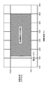
- FIG. 2 is a diagram illustrating a fiber generation process of the fiber assembly 202 according to the embodiment.
- the airflow nozzle 107 that blows out the high temperature airflow 401 and the resin discharge nozzle 106 that discharges the molten resin 400 are installed at a certain distance.
- the constant distance is, for example, not less than 0.5 mm and not more than 5 mm. If the distance is too close, the force to pulverize the molten resin 400 tends to work to make short fibers, and if the distance is too far, the molten resin 400 is difficult to be drawn into the high-temperature airflow 401.
- the airflow nozzle 107 and the resin discharge nozzle 106 are both oriented in the horizontal direction, and the direction in which the high-temperature airflow 401 blows out and the direction in which the molten resin 400 is discharged are parallel to each other.
- the molten resin 400 discharged from the resin discharge nozzle 106 is gently drawn into the high temperature air flow 401 blown out from the air flow nozzle 107, and is stretched in the horizontal direction to be fiberized. Thereby, as shown in FIG. 1, the ultrafine fiber 500 with a long fiber length is produced
- the ultrafine fibers 500 generated in the stretching unit 113 are carried in an air stream, collected by the collector 200, and become an ultrafine fiber aggregate 202.
- the collection body 200 moves at a constant speed, collects the ultrafine fibers 500 conveyed by the airflow with a uniform thickness and weight, and forms a sheet-like uniform fiber assembly 202.
- the collection body 200 may be a roll or a conveyor, for example.
- the nonwoven fabric 201 is installed on the surface of the collector 200. This nonwoven fabric 201 makes it easy to collect and handle the fiber assembly 202.
- the thickness and the weight per unit area of the fiber assembly 202 are determined by the distance from the tip of the resin discharge nozzle 106 to the collection body 200 and the moving speed of the collection body 200.
- tip of the resin discharge nozzle 106 to the collection body 200 1000 mm or more and 5000 mm or less are preferable. If the distance is too short, the stretching required for fiberization of the molten resin 400 is insufficient, and it becomes difficult to form the ultrafine fiber 500, and the fiber assembly 202 is crushed and easily densified by the pressure of the high-temperature airflow 401. On the other hand, if the distance is too long, the ultrafine fibers 500 do not reach the collection body 200 and the collection becomes difficult. For this reason, the distance from the tip of the resin discharge nozzle 106 to the collector 200 may be set appropriately in accordance with the relationship with the density.
- the melt viscosity of the fiber assembly is an important factor in melting and spinning thermoplastic resin powders or pellets. This melt viscosity can be verified by heating and melting a fiber assembly composed of spun ultrafine fibers again.
- the ultrafine fiber here has a fiber diameter distribution, and means that the fiber diameter of the fiber assembly is 1 ⁇ m or less in terms of median diameter. However, a fiber aggregate having a median diameter of 1 ⁇ m or less does not necessarily mean that fibers having a fiber diameter larger than 1 ⁇ m are not included.
- the fiber assembly of the present embodiment has a median diameter of 1 ⁇ m or less, thereby significantly increasing the surface area, thereby reducing the airflow resistance, improving the adsorption characteristics, and improving the heat insulation performance.
- Various characteristics such as improved sound absorption characteristics are manifested.
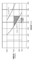
- 3 to 8 are diagrams showing the melt viscosity characteristics of the fiber assembly according to the embodiment.
- the horizontal axis indicates the melting temperature
- the vertical axis indicates the melt viscosity.
- region shown with an oblique line has shown the preferable condition range (it describes with an ultrafine fiber production
- the melt viscosity of the fiber assembly is preferably 100 mPa ⁇ s or more and 1000 mPa ⁇ s or less as shown in FIG.
- the melt viscosity is smaller than the range, the weight average molecular weight Mw of the resin becomes too small, so that the function of intermolecular entanglement is weakened and it is difficult to form a fiber shape. That is, even when the above-described production method (spinning method) is used, the melt resin is easily cut when stretched, so that it is difficult to form a fiber, and instead, an aggregate containing many spherical particles is formed. The strength is significantly reduced.
- the melt viscosity is larger than the above range, the fiber diameter of the fiber assembly becomes 1 ⁇ m or more, and ultrafine fibers cannot be obtained.
- the melt viscosity of the fiber assembly is more preferably 100 mPa ⁇ s or more and 1000 mPa ⁇ s or less, with 400 ° C. being the upper limit of the melting temperature, as shown in FIG. If the melting temperature is higher than that range, the thermal decomposition proceeds rapidly even if the resin is blocked from oxygen (for example, nitrogen atmosphere or sealed state), and the weight average molecular weight Mw of the resin decreases. Occurs at the spinning stage. Therefore, for the same reason as described above, it is difficult to form a fiber, and the strength of the produced fiber assembly is also reduced.
- the melt viscosity of the fiber assembly is 100 mPa ⁇ s or more and 1000 mPa ⁇ s or less, with the temperature lower by 10 ° C. higher than the melting point of the thermoplastic resin as shown in FIG. It is more preferable. If the melting temperature is lower than that range, even if the resin residence time in the heating unit 112 is sufficiently secured, the resin discharge nozzle 106 tends to cause unmelted resin, which causes spinning instability.
- the melt viscosity of the fiber assembly satisfies the relational expression of 10 11 T ⁇ 3.6 mPa ⁇ s or more and 10 12 T ⁇ 3.6 mPa ⁇ s or less as shown in FIG. More preferably in the melt viscosity range.
- T indicates the melting temperature of the fiber assembly
- Y indicates the melt viscosity of the fiber assembly (hereinafter the same in FIGS. 7 and 8).
- the melt viscosity is lower than this relational expression, ultrafine fibers are produced, but a certain amount of spherical particles are contained, and the strength of the fiber assembly is lowered.
- the melt viscosity of the fiber assembly is 200 mPa ⁇ s or more and 600 mPa ⁇ s or less, and 2 ⁇ 10 11 T ⁇ 3.6 mPa ⁇ s or more, as shown in FIG. More preferably, it is in a melt viscosity range satisfying the relational expression of 10 12 T ⁇ 3.6 mPa ⁇ s or less.
- the melt viscosity is lower than this relational expression, although spherical particles are not substantially included, ultrafine fibers having a short fiber length are easily generated, and it is difficult to obtain strength even if the weight of the fiber assembly is increased.
- the fiber diameter is 0.7 ⁇ m or less, and the characteristics as an ultrafine fiber are improved.
- the melt viscosity of the fiber assembly is 200 mPa ⁇ s or more and 600 mPa ⁇ s or less in a temperature range of 10 ° C. higher than the melting point of the thermoplastic resin and 350 ° C. or less, as shown in FIG. Further, it is more preferable that the viscosity is in a melt viscosity range satisfying a relational expression of 2 ⁇ 10 11 T ⁇ 3.6 mPa ⁇ s to 10 12 T ⁇ 3.6 mPa ⁇ s.
- the density of the fiber aggregate is more preferably 0.01 g / cm 3 or more and is 0.040 g / cm 3 or less. A higher quality fiber assembly can be realized.
- the thickness of the fiber assembly is more preferably larger than 10 mm and smaller than 100 mm.
- a fiber assembly composed of ultrafine fibers of 1 ⁇ m or less is difficult to maintain a thickness exceeding 10 mm if the strength is low, but by increasing the fiber strength as in this embodiment, the thickness of the fiber assembly can be reduced. Can be maintained.
- a fiber assembly made of ultrafine fibers of 1 ⁇ m or less and having a thickness exceeding 10 mm can be applied to a wide range of uses such as a sound absorbing material.
- the fiber assembly is more preferably thicker than 10 mm and thinner than 30 mm.
- the fiber assembly of the present embodiment has high strength while being a very fine fiber having a median diameter of 1 ⁇ m or less obtained from the fiber diameter distribution.
- a fiber assembly having a single fiber diameter of 500 nm to 1000 nm and a strength of 1N or more can be obtained (see the examples described later).
- Example Next, examples of the present disclosure will be described. In addition, a present Example does not limit embodiment of this indication mentioned above. First, items and an evaluation method used when evaluating this example will be described.
- Fiber diameter (median diameter) Using a scanning electron microscope Phenom G2 pro manufactured by PHENOM-World, 200 fibers were randomly selected from a two-dimensional image of a fiber assembly magnified 10,000 times, and the fiber diameters were measured. The sample was pre-sputtered with Au to prevent charging. Based on the measurement result of the fiber diameter, the median diameter was calculated.
- Fiber Strength Texture Analyzer TA Manufactured by Stable Micro Systems XT. The tensile strength of the fiber assembly was measured using plus. The sample size was 100 ⁇ 15 mm, and the fiber weight (denoted as w in FIG. 9 described later) was three types: 0.3 g, 0.5 g, and 0.7 g. In the tensile test, the long side direction of the sample was gripped by 20 mm each, the upper end was pulled up in the long side direction at a speed of 1 mm / sec with the lower end fixed, and the maximum strength when the fiber assembly was cut was measured. The measurement result was defined as fiber strength.
- Weight average molecular weight Mw The weight average molecular weight Mw was measured using Waters high-temperature gel permeation chromatography GPC / V2000. As measurement conditions, the eluent was o-dichlorobenzene, the temperature was 145 ° C., the sample concentration was 1.0 g / L, and the flow rate was 1.0 mL / min. A differential refractometer was used as a detector.
- a single-axis full flight screw pump was used as the screw pump 103, and the material was conveyed to the heating unit 112.
- a cylinder 105 having an inner diameter of 20 mm and a length of 100 mm was used.
- the rotational speed of the screw pump 103 was 5 rpm.
- the residence time of the molten resin in the heating unit 112 was approximately 10 minutes.
- a total of five band heaters were installed in the heating unit 112 and set so as to reach the molten resin temperature of each example described later.
- the diameter of the resin discharge nozzle 106 was 0.5 mm.
- the compressed air was set to 0.3 MPa, and the high-speed airflow was heated using a torch heater so as to have the temperature of each example described later.
- the inner diameter of the air nozzle was 1 mm.
- a roll was used as the collection body 200 to collect the fiber assembly.
- the outer diameter of the roll was 50 cm, and the rotation speed of the roll was 1 rpm.
- a nonwoven fabric 201 made of polypropylene and having a basis weight of 20 g / m 2 was installed on the surface of the roll.
- a melting (spinning) temperature 390 ° C. and a molten resin discharge rate of 3.0 g / min, spinning at an air speed of 50 m / sec and an air temperature of 400 ° C., and collecting the fibers on the nonwoven fabric.
- An assembly was produced.
- the molten resin viscosity measured at the melting (spinning) temperature was 200 mPa ⁇ s.
- the fiber aggregate produced had a fiber diameter of 0.70 ⁇ m, a thickness of 28 mm, a density of 0.016 g / cm 3 , and fiber strengths of 1.0 N, 2.1 N, and 3.2 N, respectively.
- Mw 48,700, melting point 154 ° C., homopolymer
- Mw 34,600, melting point 154 ° C., homopolymer
- the fiber strength of the produced fiber assembly can be as large as 4.5 N, 7.0 N, and 10.0 N, respectively, the obtained fiber diameter is 1.32 ⁇ m, which does not lead to thinning.
- the fiber assembly had a thickness of 16 mm and a density of 0.029 g / cm 3 .
- the fiber strength of the produced fiber assembly was as small as 0.2 N at any fiber weight, and a fiber assembly containing many spherical particles was obtained.
- the fiber diameter was 0.7 ⁇ m.
- the fiber assembly had a thickness of 10 mm and a density of 0.044 g / cm 3 .
- FIG. 9 is a diagram showing the characteristics of the fiber assembly 202 of the example and the comparative example according to the embodiment.
- FIG. 9 collectively shows the above-described Examples 1 to 3 and Comparative Examples 1 to 3.
- ⁇ means “very good”, a condition that a fiber aggregate having a fiber diameter of 1 ⁇ m or less and a fiber strength of 1.0 N or more was obtained. Is shown. “ ⁇ ” means “good”, and indicates the condition under which a fiber assembly having a fiber diameter of 1 ⁇ m or less was obtained. Further, “x” means “bad”, and indicates the condition under which a fiber aggregate having a fiber diameter of 1 ⁇ m or more was obtained.
- the fiber assembly of the present disclosure can be applied to a wide range of industrial uses such as a sound absorbing material, a heat insulating material, an adsorbing material, and a filter.
Landscapes
- Engineering & Computer Science (AREA)
- Textile Engineering (AREA)
- Physics & Mathematics (AREA)
- Acoustics & Sound (AREA)
- Multimedia (AREA)
- Chemical & Material Sciences (AREA)
- Chemical Kinetics & Catalysis (AREA)
- General Chemical & Material Sciences (AREA)
- Spinning Methods And Devices For Manufacturing Artificial Fibers (AREA)
- Nonwoven Fabrics (AREA)
Abstract
L'invention concerne un ensemble de fibres obtenues par filage par fusion d'une résine thermoplastique, le diamètre des fibres de l'ensemble de fibres présentant un diamètre moyen inférieur ou égal à 1 µm, et la viscosité à l'état fondu de l'ensemble de fibres étant de 100 à 1 000 mPa∙s.
Priority Applications (3)
| Application Number | Priority Date | Filing Date | Title |
|---|---|---|---|
| EP16877962.7A EP3396039A4 (fr) | 2015-12-21 | 2016-12-13 | Ensemble de fibres |
| CN201680026931.6A CN107614773A (zh) | 2015-12-21 | 2016-12-13 | 纤维集合体 |
| US15/564,756 US20180105955A1 (en) | 2015-12-21 | 2016-12-13 | Fiber assembly |
Applications Claiming Priority (4)
| Application Number | Priority Date | Filing Date | Title |
|---|---|---|---|
| JP2015-248749 | 2015-12-21 | ||
| JP2015248749 | 2015-12-21 | ||
| JP2016187206A JP6210422B2 (ja) | 2015-12-21 | 2016-09-26 | 繊維集合体 |
| JP2016-187206 | 2016-09-26 |
Publications (1)
| Publication Number | Publication Date |
|---|---|
| WO2017110057A1 true WO2017110057A1 (fr) | 2017-06-29 |
Family
ID=59089914
Family Applications (1)
| Application Number | Title | Priority Date | Filing Date |
|---|---|---|---|
| PCT/JP2016/005117 Ceased WO2017110057A1 (fr) | 2015-12-21 | 2016-12-13 | Ensemble de fibres |
Country Status (1)
| Country | Link |
|---|---|
| WO (1) | WO2017110057A1 (fr) |
Cited By (3)
| Publication number | Priority date | Publication date | Assignee | Title |
|---|---|---|---|---|
| WO2019059360A1 (fr) * | 2017-09-22 | 2019-03-28 | オーウエル株式会社 | Tissu non-tissé fabriqué par fusion-soufflage, son utilisation et son procédé de fabrication |
| JPWO2020203932A1 (fr) * | 2019-03-29 | 2020-10-08 | ||
| JP2021534303A (ja) * | 2018-08-22 | 2021-12-09 | ビーエイエスエフ・ソシエタス・エウロパエアBasf Se | 安定化された回転成形ポリオレフィン |
Citations (12)
| Publication number | Priority date | Publication date | Assignee | Title |
|---|---|---|---|---|
| JPS55132708A (en) * | 1979-04-04 | 1980-10-15 | Asahi Chem Ind Co Ltd | Production of ultrafine thermoplastic polymer filament yarn |
| JPS636107A (ja) * | 1986-06-24 | 1988-01-12 | Asahi Chem Ind Co Ltd | ポリプロピレン極細繊維の製造方法 |
| JPH03249207A (ja) * | 1990-02-27 | 1991-11-07 | Toyobo Co Ltd | オレフィン系極細繊維の製造方法 |
| JPH03279450A (ja) * | 1990-03-23 | 1991-12-10 | Asahi Chem Ind Co Ltd | 極細繊維不織シート及びその製造方法 |
| JP2007239114A (ja) * | 2006-03-06 | 2007-09-20 | Univ Of Fukui | 溶融型静電紡糸方法及び極細繊維 |
| JP2009062630A (ja) * | 2007-09-04 | 2009-03-26 | Univ Of Fukui | 溶融型静電紡糸方法及び極細繊維 |
| JP4574262B2 (ja) | 2004-07-21 | 2010-11-04 | 旭化成せんい株式会社 | 吸音性積層体およびその製造法 |
| JP2011501790A (ja) * | 2007-10-23 | 2011-01-13 | ピーピージー インダストリーズ オハイオ, インコーポレイテッド | 電気機械的紡績による繊維形成 |
| JP2011241509A (ja) | 2010-05-19 | 2011-12-01 | Toyota Boshoku Corp | 溶融紡糸方法及び溶融紡糸装置 |
| JP2013134427A (ja) | 2011-12-27 | 2013-07-08 | Kureha Corp | 脂肪族ポリエステル不織布の積層体を備える吸音材 |
| JP5378960B2 (ja) | 2009-11-24 | 2013-12-25 | 日本バイリーン株式会社 | 紡糸装置、不織布製造装置、不織布の製造方法及び不織布 |
| JP2014088639A (ja) | 2012-10-30 | 2014-05-15 | Kasen Nozuru Seisakusho:Kk | 極細繊維不織布の製造装置 |
-
2016
- 2016-12-13 WO PCT/JP2016/005117 patent/WO2017110057A1/fr not_active Ceased
Patent Citations (12)
| Publication number | Priority date | Publication date | Assignee | Title |
|---|---|---|---|---|
| JPS55132708A (en) * | 1979-04-04 | 1980-10-15 | Asahi Chem Ind Co Ltd | Production of ultrafine thermoplastic polymer filament yarn |
| JPS636107A (ja) * | 1986-06-24 | 1988-01-12 | Asahi Chem Ind Co Ltd | ポリプロピレン極細繊維の製造方法 |
| JPH03249207A (ja) * | 1990-02-27 | 1991-11-07 | Toyobo Co Ltd | オレフィン系極細繊維の製造方法 |
| JPH03279450A (ja) * | 1990-03-23 | 1991-12-10 | Asahi Chem Ind Co Ltd | 極細繊維不織シート及びその製造方法 |
| JP4574262B2 (ja) | 2004-07-21 | 2010-11-04 | 旭化成せんい株式会社 | 吸音性積層体およびその製造法 |
| JP2007239114A (ja) * | 2006-03-06 | 2007-09-20 | Univ Of Fukui | 溶融型静電紡糸方法及び極細繊維 |
| JP2009062630A (ja) * | 2007-09-04 | 2009-03-26 | Univ Of Fukui | 溶融型静電紡糸方法及び極細繊維 |
| JP2011501790A (ja) * | 2007-10-23 | 2011-01-13 | ピーピージー インダストリーズ オハイオ, インコーポレイテッド | 電気機械的紡績による繊維形成 |
| JP5378960B2 (ja) | 2009-11-24 | 2013-12-25 | 日本バイリーン株式会社 | 紡糸装置、不織布製造装置、不織布の製造方法及び不織布 |
| JP2011241509A (ja) | 2010-05-19 | 2011-12-01 | Toyota Boshoku Corp | 溶融紡糸方法及び溶融紡糸装置 |
| JP2013134427A (ja) | 2011-12-27 | 2013-07-08 | Kureha Corp | 脂肪族ポリエステル不織布の積層体を備える吸音材 |
| JP2014088639A (ja) | 2012-10-30 | 2014-05-15 | Kasen Nozuru Seisakusho:Kk | 極細繊維不織布の製造装置 |
Non-Patent Citations (1)
| Title |
|---|
| See also references of EP3396039A4 * |
Cited By (6)
| Publication number | Priority date | Publication date | Assignee | Title |
|---|---|---|---|---|
| WO2019059360A1 (fr) * | 2017-09-22 | 2019-03-28 | オーウエル株式会社 | Tissu non-tissé fabriqué par fusion-soufflage, son utilisation et son procédé de fabrication |
| JP2019056190A (ja) * | 2017-09-22 | 2019-04-11 | オーウエル株式会社 | メルトブローン不織布及びその用途ならびにその製造方法 |
| JP2021534303A (ja) * | 2018-08-22 | 2021-12-09 | ビーエイエスエフ・ソシエタス・エウロパエアBasf Se | 安定化された回転成形ポリオレフィン |
| JP7478135B2 (ja) | 2018-08-22 | 2024-05-02 | ビーエーエスエフ ソシエタス・ヨーロピア | 安定化された回転成形ポリオレフィン |
| JPWO2020203932A1 (fr) * | 2019-03-29 | 2020-10-08 | ||
| JP7573515B2 (ja) | 2019-03-29 | 2024-10-25 | 株式会社カネカ | メルトブローン不織布の製造方法、及びメルトブローン不織布 |
Similar Documents
| Publication | Publication Date | Title |
|---|---|---|
| JP6210422B2 (ja) | 繊維集合体 | |
| US8828530B2 (en) | Heat-storing moldings | |
| EP2527503B1 (fr) | Production de nanofibres grâce à un filage par fusion | |
| CN106715774B (zh) | 非织造网 | |
| JP2011241510A (ja) | 溶融紡糸方法及び溶融紡糸装置 | |
| JP6587703B2 (ja) | 微細繊維の製造方法及び微細繊維の製造装置 | |
| WO2017110057A1 (fr) | Ensemble de fibres | |
| JP6337093B2 (ja) | 極細繊維の製造方法 | |
| US20190161889A1 (en) | Polymeric nanofibers and nanofibrous web | |
| Zhou et al. | Study on spinnability of PP/PU blends and preparation of PP/PU bi-component melt blown nonwovens | |
| CN1218072C (zh) | 超吸湿纤维的非织造织物及其制造方法 | |
| Nayak et al. | Mechanism of nanofibre fabrication by meltblowing | |
| JP5565971B2 (ja) | ポリ乳酸樹脂とポリエチレンテレフタレート樹脂からなるポリマーアロイおよびその製造方法 | |
| CN116695280B (zh) | 一种三维螺旋结构弹性es纤维及其制备方法 | |
| JPH01156561A (ja) | ポリプロピレン極細繊維不織布 | |
| JPH03249249A (ja) | オレフイン系極細繊維不織布 | |
| JP7673088B2 (ja) | 繊維不織布、フィルタ及び繊維不織布の製造方法 | |
| CN110644140B (zh) | 一种熔喷纤维及其制备方法和用途 | |
| JP7730619B2 (ja) | 繊維不織布の製造方法 | |
| JP2014240528A (ja) | 立体規則性ポリスチレン系複合紡糸繊維及び短繊維 | |
| JPH1121753A (ja) | スリット紡糸メルトブロー不織布の製造方法 |
Legal Events
| Date | Code | Title | Description |
|---|---|---|---|
| 121 | Ep: the epo has been informed by wipo that ep was designated in this application |
Ref document number: 16877962 Country of ref document: EP Kind code of ref document: A1 |
|
| REEP | Request for entry into the european phase |
Ref document number: 2016877962 Country of ref document: EP |
|
| WWE | Wipo information: entry into national phase |
Ref document number: 15564756 Country of ref document: US |
|
| NENP | Non-entry into the national phase |
Ref country code: DE |