WO2017110928A1 - 船舶用推進装置 - Google Patents
船舶用推進装置 Download PDFInfo
- Publication number
- WO2017110928A1 WO2017110928A1 PCT/JP2016/088217 JP2016088217W WO2017110928A1 WO 2017110928 A1 WO2017110928 A1 WO 2017110928A1 JP 2016088217 W JP2016088217 W JP 2016088217W WO 2017110928 A1 WO2017110928 A1 WO 2017110928A1
- Authority
- WO
- WIPO (PCT)
- Prior art keywords
- gear
- shaft
- input shaft
- reverse
- clutch
- Prior art date
- Legal status (The legal status is an assumption and is not a legal conclusion. Google has not performed a legal analysis and makes no representation as to the accuracy of the status listed.)
- Ceased
Links
Images




Classifications
-
- B—PERFORMING OPERATIONS; TRANSPORTING
- B63—SHIPS OR OTHER WATERBORNE VESSELS; RELATED EQUIPMENT
- B63H—MARINE PROPULSION OR STEERING
- B63H23/00—Transmitting power from propulsion power plant to propulsive elements
- B63H23/30—Transmitting power from propulsion power plant to propulsive elements characterised by use of clutches
-
- B—PERFORMING OPERATIONS; TRANSPORTING
- B63—SHIPS OR OTHER WATERBORNE VESSELS; RELATED EQUIPMENT
- B63H—MARINE PROPULSION OR STEERING
- B63H23/00—Transmitting power from propulsion power plant to propulsive elements
- B63H23/02—Transmitting power from propulsion power plant to propulsive elements with mechanical gearing
- B63H23/08—Transmitting power from propulsion power plant to propulsive elements with mechanical gearing with provision for reversing drive
-
- F—MECHANICAL ENGINEERING; LIGHTING; HEATING; WEAPONS; BLASTING
- F16—ENGINEERING ELEMENTS AND UNITS; GENERAL MEASURES FOR PRODUCING AND MAINTAINING EFFECTIVE FUNCTIONING OF MACHINES OR INSTALLATIONS; THERMAL INSULATION IN GENERAL
- F16H—GEARING
- F16H3/00—Toothed gearings for conveying rotary motion with variable gear ratio or for reversing rotary motion
- F16H3/02—Toothed gearings for conveying rotary motion with variable gear ratio or for reversing rotary motion without gears having orbital motion
- F16H3/08—Toothed gearings for conveying rotary motion with variable gear ratio or for reversing rotary motion without gears having orbital motion exclusively or essentially with continuously meshing gears, that can be disengaged from their shafts
- F16H3/14—Gearings for reversal only
-
- B—PERFORMING OPERATIONS; TRANSPORTING
- B63—SHIPS OR OTHER WATERBORNE VESSELS; RELATED EQUIPMENT
- B63B—SHIPS OR OTHER WATERBORNE VESSELS; EQUIPMENT FOR SHIPPING
- B63B35/00—Vessels or similar floating structures specially adapted for specific purposes and not otherwise provided for
- B63B2035/009—Wind propelled vessels comprising arrangements, installations or devices specially adapted therefor, other than wind propulsion arrangements, installations, or devices, such as sails, running rigging, or the like, and other than sailboards or the like or related equipment
-
- B—PERFORMING OPERATIONS; TRANSPORTING
- B63—SHIPS OR OTHER WATERBORNE VESSELS; RELATED EQUIPMENT
- B63H—MARINE PROPULSION OR STEERING
- B63H5/00—Arrangements on vessels of propulsion elements directly acting on water
- B63H5/07—Arrangements on vessels of propulsion elements directly acting on water of propellers
- B63H2005/075—Arrangements on vessels of propulsion elements directly acting on water of propellers using non-azimuthing podded propulsor units, i.e. podded units without means for rotation about a vertical axis, e.g. rigidly connected to the hull
-
- B—PERFORMING OPERATIONS; TRANSPORTING
- B63—SHIPS OR OTHER WATERBORNE VESSELS; RELATED EQUIPMENT
- B63H—MARINE PROPULSION OR STEERING
- B63H23/00—Transmitting power from propulsion power plant to propulsive elements
- B63H23/02—Transmitting power from propulsion power plant to propulsive elements with mechanical gearing
- B63H23/10—Transmitting power from propulsion power plant to propulsive elements with mechanical gearing for transmitting drive from more than one propulsion power unit
- B63H23/18—Transmitting power from propulsion power plant to propulsive elements with mechanical gearing for transmitting drive from more than one propulsion power unit for alternative use of the propulsion power units
- B63H23/20—Transmitting power from propulsion power plant to propulsive elements with mechanical gearing for transmitting drive from more than one propulsion power unit for alternative use of the propulsion power units with separate forward and astern propulsion power units, e.g. turbines
-
- F—MECHANICAL ENGINEERING; LIGHTING; HEATING; WEAPONS; BLASTING
- F16—ENGINEERING ELEMENTS AND UNITS; GENERAL MEASURES FOR PRODUCING AND MAINTAINING EFFECTIVE FUNCTIONING OF MACHINES OR INSTALLATIONS; THERMAL INSULATION IN GENERAL
- F16D—COUPLINGS FOR TRANSMITTING ROTATION; CLUTCHES; BRAKES
- F16D41/00—Freewheels or freewheel clutches
-
- F—MECHANICAL ENGINEERING; LIGHTING; HEATING; WEAPONS; BLASTING
- F16—ENGINEERING ELEMENTS AND UNITS; GENERAL MEASURES FOR PRODUCING AND MAINTAINING EFFECTIVE FUNCTIONING OF MACHINES OR INSTALLATIONS; THERMAL INSULATION IN GENERAL
- F16D—COUPLINGS FOR TRANSMITTING ROTATION; CLUTCHES; BRAKES
- F16D41/00—Freewheels or freewheel clutches
- F16D41/04—Freewheels or freewheel clutches combined with a clutch for locking the driving and driven members
Definitions
- the present invention relates to a marine vessel propulsion device.
- Patent Document 1 discloses a propulsion device provided with a hydraulic forward / reverse switching clutch that transmits the rotation direction of a propeller shaft to an input shaft so that forward / reverse switching is possible.
- the propulsion device is interposed between the input shaft drivingly connected to the engine, the output shaft including the propeller shaft, the input shaft and the output shaft, and the hydraulic wet multi-plate clutch for forward / reverse switching of the output shaft, Is provided.
- the marine vessel propulsion device of the present invention includes an input shaft connected to a drive source, a forward gear provided on the input shaft, a reverse gear provided on the input shaft, the forward gear, and the reverse gear.
- An output gear that meshes with the output gear, an output shaft that transmits the power of the output gear, a forward / reverse switching clutch that transmits the power of the input shaft to the forward gear or the reverse gear, and the input shaft.
- a forward one-way clutch that connects between the forward gear and the input shaft when the forward gear is faster than the rotational speed of the input shaft, and is interposed between the forward gear and the input shaft;
- a reverse one-way clutch that connects the reverse gear and the input shaft when the reverse gear is faster than the rotational speed of the input shaft. Is provided.
- the marine vessel propulsion apparatus of the present invention it is possible to prevent the propeller from rotating.
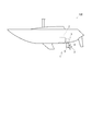
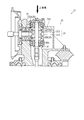
- FIG. It is a side view which shows the ship provided with a propulsion apparatus. It is an enlarged view of the propulsion apparatus in FIG. It is a fragmentary sectional view of the propulsion apparatus located in a ship. It is the elements on larger scale which show the support structure to the input shaft of the gear in FIG.
- A A diagram showing the presence or absence of rotation of the input shaft and gear when the engine is driven, and the direction of rotation.
- B Presence or absence of rotation of the input shaft and gear when the propeller is idle, and the direction of rotation.
- FIG. It is a fragmentary sectional view of the propulsion device in a second embodiment.
- FIG. 4 is a diagram showing the presence / absence of rotation of a reverse drive shaft and a cylindrical gear and the direction during rotation.
- a ship 100 provided with the propulsion device 1 will be described with reference to FIG.
- the axial direction of the propeller shaft 15 or the output shaft 54 as an output shaft described later is defined as the front-rear direction
- the side on which the engine 2 described later is disposed is the front
- the side on which the propeller 3 is disposed It shall be described as being defined as the rear.
- power from the engine 2 as a drive source is transmitted to the propeller 3 attached to the downstream end of the power transmission path of the propulsion device 1, so that the propeller 3 rotates and propels the ship 100.
- the propulsion device 1 is provided such that a part of the propulsion device 1 projects downward through an opening 4 provided on the bottom of the ship 100.
- the propulsion device 1 includes an upper unit 5 located in the ship and a lower unit 6 extending downward from the opening.
- the upper unit 5 is connected to the flywheel housing 2 ⁇ / b> A of the engine 2 at the front portion thereof, and the lower unit 6 extending downward through the opening 4 is connected to the lower portion thereof.
- An engine bed 7 is formed integrally with the hull around the opening 4 at the bottom of the ship.
- an anti-vibration component for installation of the propulsion device 1 is fixed, and a seal flange 8 that supports the upper unit 5 and an engine 2 to which the propulsion device 1 is fastened are attached.
- the propulsion device 1 is connected to the engine 2 and provided over the inside and outside of the ship through the opening 4 provided in the ship bottom.
- the upper unit 5 includes an input shaft 11 connected to the engine 2, a part of the intermediate shaft 12 provided so as to penetrate from the upper unit 5 to the lower unit 6, and a gear that transmits power from the input shaft 11 to the intermediate shaft 12.
- the lower unit 6 includes a part of the intermediate shaft 12, a propeller shaft 15 to which the propeller 3 is fixed at one end, a gear mechanism 16 that transmits power from the intermediate shaft 12 to the propeller shaft 15, and a part of the intermediate shaft 12.
- the power from the engine 2 is transmitted to the input shaft 11 in the upper unit 5.
- the power transmitted to the input shaft 11 is transmitted to the intermediate shaft 12 via the gear mechanism 13.
- the power transmitted to the intermediate shaft 12 via the gear mechanism 13 is transmitted to the propeller shaft 15 via the gear mechanism 16 (gears 16A and 16B) provided at the lower end thereof.
- the propeller 3 By transmitting power to the propeller shaft 15, the propeller 3 provided at one end of the propeller shaft 15 is rotated and the ship 100 is propelled.
- the propulsion device 1 is configured such that power is transmitted from the input shaft 11 connected to the drive source to the output shaft (the intermediate shaft 12 and the propeller shaft 15) via the gear mechanism.
- the input shaft 11 is arranged with the front-rear direction as a longitudinal direction, and is provided so as to extend rearward from the engine 2.
- One end of the input shaft 11 is connected to the engine 2 in the flywheel housing 2 ⁇ / b> A of the engine 2.
- the gear mechanism 13 is constituted by a bevel gear.
- the gear mechanism 13 includes a forward gear 13A, a reverse gear 13B, and an output gear 13C.
- the forward gear 13 ⁇ / b> A and the reverse gear 13 ⁇ / b> B as the first gear are provided on the input shaft 11 and connected to the unit clutch 17.
- the output gear 13 ⁇ / b> C as the second gear is provided so as to mesh with the forward gear 13 ⁇ / b> A and the reverse gear 13 ⁇ / b> B.
- the input shaft 11 provided with the forward gear 13A and the reverse gear 13B is provided with a unit clutch 17 for connecting and disconnecting power from the engine 2.
- the unit clutch 17 is configured as a forward / reverse switching clutch having a wet multi-plate clutch.
- the unit clutch 17 includes a forward clutch 17A and a reverse clutch 17B.
- the forward clutch 17A is provided so as to be connectable to the forward gear 13A constituting the gear mechanism 13
- the reverse clutch 17B is provided so as to be connectable to the reverse gear 13B constituting the gear mechanism 13.
- the intermediate shaft 12 is arranged with the vertical direction as the longitudinal direction, and is provided through the lower portion of the upper unit 5.
- the upper end of the intermediate shaft 12 is connected to the output gear 13C, and the output gear 13C and the intermediate shaft 12 rotate integrally.
- the forward clutch 17A or the reverse clutch 17B is operated, so that power can be transmitted from the input shaft 11 to the forward gear 13A or from the input shaft 11 to the reverse gear 13B.
- the gears (forward gear 13A and reverse gear 13B) provided on the input shaft 11 are connected to the input shaft 11 via the forward one-way clutch 18A and the reverse one-way clutch 18B. Connected to.
- the forward one-way clutch 18A and the reverse one-way clutch 18B are formed in a substantially cylindrical shape and are mounted by being press-fitted into the forward gear 13A and the reverse gear 13B, respectively.
- the forward one-way clutch 18A and the reverse one-way clutch 18B are configured such that the central portion in the axial direction functions as a clutch, and both end portions in the axial direction function as bearings.
- the forward one-way clutch 18A and the reverse one-way clutch 18B act when the rotational speed of the shaft or gear on the output shaft (propeller shaft 15) side is faster than the rotational speed of the shaft or gear on the input shaft 11 side.
- the action means that the shaft or gear on the output shaft side of the forward one-way clutch 18A and the reverse one-way clutch 18B and the shaft or gear on the input shaft 11 side can mesh (power transmission is possible).
- FIG. 5 the input shaft 11, the forward gear 13A, and the reverse gear 13B are schematically shown in a rear view.
- the unit clutch 17 When the engine 2 is driven and the unit clutch 17 is in the forward position, the unit clutch 17 is connected to the forward gear 13A, and the forward gear is connected via the unit clutch 17 as the input shaft 11 rotates. 13A rotates in the same direction. Since the reverse gear 13B is not connected to the unit clutch 17, it rotates in the opposite direction to the input shaft 11 as the output gear 13C rotates. Since the rotation direction of the reverse gear 13B is opposite to the rotation direction of the input shaft 11, the reverse one-way clutch 18B does not act, and the reverse gear 13B can idle.
- the unit clutch 17 When the engine 2 is driven and the unit clutch 17 is in the reverse position, the unit clutch 17 is connected to the reverse gear 13B, and the reverse gear is connected via the unit clutch 17 as the input shaft 11 rotates. 13B rotates in the same direction. Since the forward gear 13A is not connected to the unit clutch 17, it rotates in the opposite direction to the input shaft 11 as the output gear 13C rotates. Since the rotation direction of the forward gear 13A is opposite to the rotation direction of the input shaft 11, the forward one-way clutch 18A does not act, and the forward gear 13A can idle.
- the idle rotation here is not limited to whether the engine 2 is driven or stopped and whether or not the unit clutch 17 is connected, but the propeller 3 moves forward when the ship 100 moves forward or backward by wind power or towing. Or it refers to turning around in response to water flow from behind.
- the presence or absence of rotation of the forward gear 13A / reverse gear 13B and the input shaft 11 when the propeller 3 is idle in the engine stopped state and the direction when the propeller 3 is rotating will be described.
- the forward gear 13A When the engine 2 is stopped and the propeller 3 is about to move forward, the forward gear 13A tries to rotate leftward.
- the forward one-way clutch 18A When the forward gear 13A tries to rotate in the left direction, the forward one-way clutch 18A is actuated to engage the forward gear 13A and the input shaft 11 (becomes a state where power transmission is possible).
- the forward gear 13A and the input shaft 11 mesh with each other, so that the engine 2 to the propeller 3 can transmit power integrally. Therefore, since the input shaft 11 is not rotating while the engine 2 is stopped, the propeller 3 is locked by the resistance force of the engine 2, and the propeller 3 can be prevented from spinning.
- the reverse gear 13B When the engine 2 is stopped and the propeller 3 is about to rotate in the reverse direction, the reverse gear 13B tries to rotate in the left direction. The reverse gear 13B tries to rotate leftward. Then, the reverse one-way clutch 18B acts, and the reverse gear 13B meshes with the input shaft 11 (power transmission is possible). The reverse gear 13B and the input shaft 11 mesh with each other, so that the engine 2 to the propeller 3 can transmit power integrally. Therefore, since the input shaft 11 is not rotating while the engine 2 is stopped, the propeller 3 is locked by the resistance force of the engine 2, and the propeller 3 can be prevented from spinning.
- the gears constituting the gear mechanism 13 are connected to the input shaft 11 via the forward one-way clutch 18A and the reverse one-way clutch 18B. Free rotation can be prevented.
- the unit clutch 17 provided in the propulsion device 1 is used regardless of the type such as a hydraulic type or a mechanical type. be able to.
- the forward one-way clutch 18A and the reverse one-way clutch 18B are applied to a configuration in which the gear constituting the gear mechanism 13 is provided on the output side of the unit clutch 17, but the present invention is not limited to this.
- the one-way clutches 38A and 38B may be applied to a configuration in which a gear constituting the gear mechanism 33 shown in another embodiment is provided on the input side of the unit clutch 37.
- a configuration in which the gear constituting the gear mechanism 33 holds the intermediate shaft 32 via the one-way clutches 38A and 38B will be described.
- the propulsion apparatus 21 of another embodiment is demonstrated using FIG.
- the propulsion device 21 includes an upper unit 25 located in the ship and a lower unit extending downward from the opening.
- the upper unit 25 is connected to the flywheel housing 2 ⁇ / b> A of the engine 2 at a front portion thereof, and a lower unit extending downward through the opening 4 is connected to a lower portion thereof.
- the upper unit 25 includes an input shaft 31 connected to the engine 2, a part of an intermediate shaft 32 provided from the upper unit 25 to the lower unit, and a gear mechanism that transmits power from the input shaft 31 to the intermediate shaft 32. 33, a unit clutch 37 that connects and disconnects transmission of power from the input shaft 31 to the intermediate shaft 32, an upper housing 25A that houses the input shaft 31, a part of the intermediate shaft 32, the gear mechanism 33, and the unit clutch 37, Is provided.
- the gear mechanism 33 is constituted by a bevel gear.
- the gear mechanism 33 includes a gear 33A, a forward gear 33B, and a reverse gear 33C.
- the gear 33A is provided on the input shaft 11 so as to mesh with the forward gear 33B and the reverse gear 33C.
- the forward gear 33B and the reverse gear 33C are provided on the intermediate shaft 32 and connected to the unit clutch 37, respectively.
- the input shaft 31 is arranged with the front-rear direction as a longitudinal direction and is provided to extend rearward from the engine 2.
- One end of the input shaft 31 is connected to the engine 2 in the flywheel housing 2 ⁇ / b> A of the engine 2.
- the other end of the input shaft 31 is connected to a gear 33A constituting a gear mechanism, and the gear 33A and the input shaft 31 rotate integrally.
- the intermediate shaft 32 is provided with a unit clutch 37 for connecting / disconnecting power from the engine 2.
- the unit clutch 37 is configured as a forward / reverse switching clutch.
- the unit clutch 37 includes a forward clutch 37A and a reverse clutch 37B.
- the forward clutch 37A is provided so as to be connectable with a forward gear 33B constituting the gear mechanism 33
- the reverse clutch 37B is provided so as to be connectable with a reverse gear 33C constituting the gear mechanism 33.
- the forward clutch 37A or the reverse clutch 37B is operated, so that power can be transmitted from the forward gear 33B to the intermediate shaft 32 or from the reverse gear 33C to the intermediate shaft 32.
- the gears (forward gear 33B / reverse gear 33C) provided on the intermediate shaft 32 are supported by the upper housing 25A and are intermediated via the one-way clutches 38A and 38B.
- the shaft 32 is held.
- the one-way clutches 38A and 38B are formed in a substantially cylindrical shape and are mounted by being press-fitted into the forward gear 33B and the reverse gear 33C, respectively.
- the one-way clutches 38A and 38B are configured such that the central portion in the axial direction functions as a clutch, and both end portions in the axial direction function as bearings.
- the one-way clutches 38A and 38B act when the rotational speed of the shaft or gear on the output shaft (propeller shaft) side is faster than the rotational speed of the shaft or gear on the input shaft 31 side.
- the action here means that the shaft or gear on the output shaft side of the one-way clutch 38A or 38B and the shaft or gear on the input shaft 31 side can mesh (power transmission is possible).
- the one-way clutches 38A and 38B are configured so as not to act when the rotation direction of the shaft or gear on the input shaft 31 side when driven in the reverse direction.
- FIG. 7 the presence / absence of rotation of the forward gear 33B / reverse gear 33C and the intermediate shaft 32 when the engine 2 is driven and when the propeller 3 is idle will be described.
- the intermediate shaft 32, the forward gear 33B, and the reverse gear 33C are schematically shown in a top view.
- the unit clutch 37 When the engine 2 is driven and the unit clutch 37 is in the forward position, the unit clutch 37 is connected to the forward gear 33B, and the intermediate shaft is connected via the unit clutch 37 as the forward gear 33B rotates. 32 rotates in the same direction. Since the reverse gear 33C is not connected to the unit clutch 37, the reverse gear 33B and the intermediate shaft 32 rotate in the opposite direction as the gear 33A rotates. At this time, the one-way clutch 38B does not act, and the reverse gear 33C can idle.
- the unit clutch 37 When the engine 2 is driven and the unit clutch 37 is in the reverse position, the unit clutch 37 is connected to the reverse gear 33C, and the intermediate shaft is connected via the unit clutch 37 as the reverse gear 33C rotates. 32 rotates in the same direction. Since the forward gear 33B is not connected to the unit clutch 37, the reverse gear 33C and the intermediate shaft 32 rotate in the opposite direction as the gear 33A rotates. At this time, the one-way clutch 38A does not act, and the forward gear 33B can idle.
- the intermediate shaft 32 When the engine 2 is stopped and the propeller 3 is about to move forward, the intermediate shaft 32 tries to rotate rightward.
- the one-way clutch 38A is actuated, and the intermediate shaft 32 and the forward gear 33B are engaged with each other (the power transmission is enabled).
- the engine 2 to the propeller 3 can transmit power integrally. Therefore, since the intermediate shaft 32 is not rotating while the engine 2 is stopped, the propeller 3 is locked by the resistance force of the engine 2, and the propeller 3 can be prevented from rotating.
- the intermediate shaft 32 When the engine 2 is stopped and the propeller 3 is going to rotate backward, the intermediate shaft 32 tries to rotate leftward.
- the one-way clutch 38B is actuated, and the intermediate shaft 32 and the reverse gear 33C mesh with each other (power transmission is possible).
- the engine 2 to the propeller 3 can transmit power integrally. Therefore, since the intermediate shaft 32 is not rotating while the engine 2 is stopped, the propeller 3 is locked by the resistance force of the engine 2, and the propeller 3 can be prevented from rotating.
- the gears constituting the gear mechanism 33 are connected to the output shaft (intermediate shaft 32) via the one-way clutches 38A and 38B, the rotational speed of the shaft on the output shaft side or the gear is the shaft on the input shaft 31 side.
- the one-way clutch 38 is provided so as to act when the rotational speed of the gear becomes faster, the propeller 3 can transmit power from the engine 2 to the propeller 3 integrally. Can be prevented.
- the gear mechanism is configured by a bevel gear, but is not limited thereto.
- a propulsion device in which the gear mechanism is formed of a cylindrical gear will be described with reference to FIGS. 8 and 9.
- the propulsion device 41 transmits propulsion from the engine 2 as a drive source to the propeller 3 attached to the downstream end of the power transmission path of the propulsion device 41, so that the propeller 3 rotates and propels the ship 101.
- the propulsion device 41 is located in the ship and is provided such that an output shaft 54 to which the propeller 3 is fixed extends substantially rearward through an opening 42 provided in the bottom of the ship 101.
- the propulsion device 41 includes an input shaft 51 connected to the engine 2, a reverse drive shaft 52 provided in parallel with the input shaft 51, a gear mechanism 53 that transmits power from the input shaft 51 to the reverse drive shaft 52, An output shaft 54 provided in parallel with the input shaft 51 and having the propeller 3 fixed to one end thereof, and a gear mechanism for transmitting power from the input shaft 51 to the output shaft 54 or from the reverse drive shaft 52 to the output shaft 54 55, an input shaft 51, a reverse drive shaft 52, an output shaft 54, and a housing 56 that houses gear mechanisms 53 and 55.
- the input shaft 51 is arranged with the front-rear direction as the longitudinal direction. One end of the input shaft 51 is connected to the engine 2 and a cylindrical gear 53A constituting the gear mechanism 53 is fixed to the other end side.
- a unit clutch 57 that connects and disconnects power transmission to the output shaft 54 is provided in the middle of the input shaft 51.
- the unit clutch 57 is connected to a cylindrical gear 55 ⁇ / b> A constituting the gear mechanism 55.
- the reverse drive shaft 52 is arranged with the longitudinal direction as the longitudinal direction.
- the reverse drive shaft 52 has a cylindrical gear 53B constituting the gear mechanism 53 fixed to the other end side.
- the cylindrical gear 53B is provided so as to mesh with the cylindrical gear 53A.
- a unit clutch 58 for connecting / disconnecting power transmission to the output shaft 54 is provided from the middle portion to one end portion of the reverse drive shaft 52.
- the unit clutch 58 is connected to a cylindrical gear 55 ⁇ / b> B constituting the gear mechanism 55.
- the output shaft 54 is disposed with the front-rear direction as the longitudinal direction.
- the output shaft 54 has a cylindrical gear 55 ⁇ / b> C constituting a gear mechanism 55 fixed to one end thereof.
- the output shaft 54 is provided through the housing 56, and the propeller 3 is fixed to the other end.
- the cylindrical gear 55C is provided to mesh with the cylindrical gears 55A and 55B.
- the unit clutch 57 is connected to the cylindrical gear 55A, power is transmitted from the input shaft 51 to the output shaft 54, whereby the output shaft 54 rotates in the forward direction and the ship 101 is propelled in the forward direction.
- the unit clutch 58 is connected to the cylindrical gear 55B, it is transmitted from the input shaft 51 to the reverse drive shaft 52 via the gear mechanism 53, and the power transmitted to the reverse drive shaft 52 is output via the gear mechanism 55.
- the output shaft 54 rotates in the reverse direction, and the ship 101 is propelled in the reverse direction.
- the propulsion device 41 is configured such that power is transmitted from the input shaft 51 (including the reverse drive shaft) connected to the drive source to the output shaft 54 via the gear mechanism.
- gears (cylindrical gear 55A and cylindrical gear 55B) constituting the gear mechanism 55 are connected to the input shaft 51 and the reverse drive shaft 52 via one-way clutches 59A and 59B.
- the one-way clutches 59A and 59B are formed in a substantially cylindrical shape and are mounted by being press-fitted into the cylindrical gear 55A and the cylindrical gear 55B, respectively.
- the one-way clutches 59A and 59B are configured such that the central portion in the axial direction functions as a clutch, and both end portions in the axial direction function as bearings.
- the one-way clutches 59A and 59B act when the rotational speed of the shaft or gear on the output shaft 54 side is faster than the rotational speed of the shaft or gear on the input shaft 51 side.
- the action here means that the shaft or gear on the output shaft 54 side of the one-way clutch 59A / 59B and the shaft or gear on the input shaft 51 side can mesh (power transmission is possible).
- the one-way clutches 59 ⁇ / b> A and 59 ⁇ / b> B are configured not to act when the rotation direction of the shaft or gear on the input shaft 51 side when driven by the engine 2 is opposite.
- the unit clutch 57 When the engine 2 is driven and the unit clutch 57 is not connected, the unit clutch 57 does not transmit power to the cylindrical gear 55A, and therefore the same direction as the rotation direction when the input shaft 51 is driven by the engine 2 It rotates in the left direction shown in FIG.
- the unit clutch 58 does not transmit power to the cylindrical gear 55B, so that the rotational direction when the reverse drive shaft 52 is driven by the engine 2 It rotates in the same direction (right direction shown in FIG. 10).
- the unit clutch 57 When the engine 2 is driven and the unit clutch 57 is connected, the unit clutch 57 is connected to the cylindrical gear 55A, and the cylindrical gear 55A rotates in the same direction as the input shaft 51 rotates.
- the unit clutch 58 When the engine 2 is driven and the unit clutch 58 is connected, the unit clutch 58 is connected to the cylindrical gear 55B, and the cylindrical gear 55B rotates in the same direction as the reverse drive shaft 52 rotates.
- the cylindrical gear 55A tries to rotate leftward via the output shaft 54.
- the one-way clutch 59A is actuated so that the cylindrical gear 55A and the input shaft 51 mesh (become able to transmit power), so that the engine 2 to the propeller 3 are integrated.
- power can be transmitted. Therefore, since the input shaft 51 is not rotating while the engine 2 is stopped, the propeller 3 is locked by the resistance force of the engine 2, and the propeller 3 can be prevented from spinning.
- the cylindrical gear 55B tries to rotate rightward via the output shaft 54.
- the one-way clutch 59B is actuated to engage the cylindrical gear 55B and the reverse drive shaft 52 (becomes a state where power can be transmitted), so that the engine 2 to the propeller 3 Becomes a state where power can be transmitted integrally. Therefore, since the reverse drive shaft 52 does not rotate while the engine 2 is stopped, the propeller 3 is locked by the resistance force of the engine 2, and the propeller 3 can be prevented from rotating freely.
- the rotation speed of the shaft on the output shaft 54 side or the gear is the axis on the input shaft 51 side.
- the one-way clutches 59A and 59B are provided so as to act when the rotational speed of the gear becomes faster, the engine 2 to the propeller 3 can be in a state where power can be transmitted integrally. 3 can be prevented.
- the present invention can be used for a marine propulsion device.
Landscapes
- Engineering & Computer Science (AREA)
- Mechanical Engineering (AREA)
- General Engineering & Computer Science (AREA)
- Chemical & Material Sciences (AREA)
- Combustion & Propulsion (AREA)
- Ocean & Marine Engineering (AREA)
- Structure Of Transmissions (AREA)
- Hydraulic Clutches, Magnetic Clutches, Fluid Clutches, And Fluid Joints (AREA)
Abstract
クラッチの種類に限らず、プロペラの遊転を防止することができる船舶用推進装置を提供することを課題とする。入力軸(11)の動力を前進用ギア(13A)又は後進用ギア(13B)に伝達する前後進切換クラッチ(17)と、入力軸(11)と前進用ギア(13A)との間に介され、前進用ギア(13A)が入力軸(11)の回転速度よりも速くなる場合に、前進用ギア(13A)と入力軸(11)とを接続する前進用ワンウェイクラッチ(18A)と、入力軸(11)と後進用ギア(13B)との間に介され、後進用ギア(13B)が入力軸(11)の回転速度よりも速くなる場合に、後進用ギア(13B)と入力軸(11)とを接続する後進用ワンウェイクラッチ(18B)と、を備える。
Description
本発明は、船舶用推進装置に関する。
特許文献1には、プロペラシャフトの回転方向を入力軸に対して正逆転切換可能に伝達する油圧式の前後進切換クラッチを備えた推進装置が開示される。推進装置は、エンジンと駆動連結された入力軸と、プロペラシャフトを含む出力軸と、入力軸と出力軸との間に介在され、出力軸の前後進切換用の油圧湿式多板形クラッチと、を備える。
特許文献1に記載の推進装置では、クラッチが油圧式であるため、エンジン停止時においてはクラッチが接続されず、風力や曳航等によって船舶が進行する際に発生するプロペラの遊転を防止することができない場合があった。
そこで、本発明は、クラッチの種類に限らず、プロペラの遊転を防止することができる船舶用推進装置を提供することを課題とする。
そこで、本発明は、クラッチの種類に限らず、プロペラの遊転を防止することができる船舶用推進装置を提供することを課題とする。
本発明の船舶用推進装置は、駆動源と連結される入力軸と、前記入力軸に設けられる前進用ギアと、前記入力軸に設けられる後進用ギアと、前記前進用ギアと前記後進用ギアとに噛み合う出力用ギアと、前記出力用ギアの動力が伝達される出力軸と、前記入力軸の動力を前記前進用ギア又は前記後進用ギアに伝達する前後進切換クラッチと、前記入力軸と前記前進用ギアとの間に介され、前記前進用ギアが前記入力軸の回転速度よりも速くなる場合に、前記前進用ギアと前記入力軸とを接続する前進用ワンウェイクラッチと、前記入力軸と前記後進用ギアとの間に介され、前記後進用ギアが前記入力軸の回転速度よりも速くなる場合に、前記後進用ギアと前記入力軸とを接続する後進用ワンウェイクラッチと、
を備えるものである。
を備えるものである。
本発明の船舶用推進装置によれば、プロペラの遊転を防止することができる。
図1を用いて、推進装置1が設けられる船舶100について説明する。以下の推進装置において、後述の出力軸としてのプロペラ軸15又は出力軸54の軸線方向を前後方向と規定するとともに、後述のエンジン2が配置される側を前方、プロペラ3が配置される側を後方と規定して、説明を行うものとする。
推進装置は、駆動源であるエンジン2からの動力が推進装置1の動力伝達経路下流端に取り付けられるプロペラ3に伝達されることで、プロペラ3が回転し船舶100を推進させるものである。推進装置1は、船舶100の船底に設けられる開口部4を通じてその一部が下方に突出するように設けられる。
推進装置は、駆動源であるエンジン2からの動力が推進装置1の動力伝達経路下流端に取り付けられるプロペラ3に伝達されることで、プロペラ3が回転し船舶100を推進させるものである。推進装置1は、船舶100の船底に設けられる開口部4を通じてその一部が下方に突出するように設けられる。
図1から図3を用いて推進装置1の全体構成について説明する。
推進装置1は、船内に位置するアッパーユニット5と開口部から下方に延出されるロアユニット6から構成される。アッパーユニット5は、その前部においてエンジン2のフライホイールハウジング2Aと連結され、その下部には、開口部4を通じて下方に延出されるロアユニット6が連結される。
推進装置1は、船内に位置するアッパーユニット5と開口部から下方に延出されるロアユニット6から構成される。アッパーユニット5は、その前部においてエンジン2のフライホイールハウジング2Aと連結され、その下部には、開口部4を通じて下方に延出されるロアユニット6が連結される。
船底の開口部4の周囲には、エンジンベッド7が船体と一体的に構成される。エンジンベッド7の上部には、推進装置1の据付け用防振部品を固定し、アッパーユニット5を支持するシールフランジ8及び推進装置1が締結されるエンジン2が取付けられる。
以上のように、推進装置1はエンジン2と連結され、船底に設けられる開口部4を通じて船内外にわたって設けられている。
以上のように、推進装置1はエンジン2と連結され、船底に設けられる開口部4を通じて船内外にわたって設けられている。
アッパーユニット5は、エンジン2と連結される入力軸11と、アッパーユニット5からロアユニット6に貫通して設けられる中間軸12の一部と、入力軸11から中間軸12に動力を伝達する歯車機構13と、入力軸11から中間軸12への動力の伝達を断接するユニットクラッチ17と、入力軸11と中間軸12の一部と歯車機構13とユニットクラッチ17とを収容するアッパーハウジング5Aと、を備える。
ロアユニット6は、中間軸12の一部と、一端にプロペラ3が固定されるプロペラ軸15と、中間軸12からプロペラ軸15に動力を伝達する歯車機構16と、中間軸12の一部とプロペラ軸15と歯車機構16とを収容するロアハウジング6Aと、を備える。
エンジン2からの動力は、アッパーユニット5内の入力軸11に伝達される。入力軸11に伝達される動力は、歯車機構13を介して中間軸12に伝達される。歯車機構13を介して中間軸12に伝達される動力は、その下端に設けられる歯車機構16(ギア16A・16B)を介してプロペラ軸15に伝達される。プロペラ軸15に動力が伝達されることで、プロペラ軸15の一端に設けられるプロペラ3が回転され船舶100は推進される。
以上のように、推進装置1は、駆動源と連結される入力軸11から出力軸(中間軸12及びプロペラ軸15)に歯車機構を介して動力が伝達される構成となっている。
以上のように、推進装置1は、駆動源と連結される入力軸11から出力軸(中間軸12及びプロペラ軸15)に歯車機構を介して動力が伝達される構成となっている。
図3を用いてアッパーユニット5内の構成について説明する。
入力軸11は、前後方向を長手方向として配置され、エンジン2から後方に向けて延出するように設けられる。入力軸11の一端は、エンジン2のフライホイールハウジング2A内においてエンジン2と接続される。
入力軸11は、前後方向を長手方向として配置され、エンジン2から後方に向けて延出するように設けられる。入力軸11の一端は、エンジン2のフライホイールハウジング2A内においてエンジン2と接続される。
歯車機構13は、ベベルギアによって構成される。歯車機構13は、前進用ギア13Aと後進用ギア13Bと出力用ギア13Cとから構成される。歯車機構13のうち、第一ギアとしての、前進用ギア13Aと後進用ギア13Bは、入力軸11に設けられるとともに、ユニットクラッチ17にそれぞれ接続される。歯車機構13のうち、第二ギアとしての、出力用ギア13Cは、前進用ギア13Aと後進用ギア13Bとそれぞれ噛み合うように設けられる。
歯車機構13のうち、前進用ギア13A及び後進用ギア13Bが設けられる入力軸11には、エンジン2からの動力を断接するユニットクラッチ17が設けられる。ユニットクラッチ17は、湿式多板クラッチを有する前後進切換クラッチとして構成される。ユニットクラッチ17は、前進用クラッチ17Aと、後進用クラッチ17Bと、を備える。前進用クラッチ17Aは、歯車機構13を構成する前進用ギア13Aと接続可能に設けられ、後進用クラッチ17Bは、歯車機構13を構成する後進用ギア13Bと接続可能に設けられる。
中間軸12は、上下方向を長手方向として配置され、アッパーユニット5の下部を貫通して設けられる。中間軸12の上端は、出力用ギア13Cに接続され、出力用ギア13Cと中間軸12とは一体的に回転する。
以上の構成において、前進用クラッチ17A又は後進用クラッチ17Bが作動されることで、入力軸11から前進用ギア13Aへ、又は、入力軸11から後進用ギア13Bへの動力伝達を可能としている。
図4に示すように、歯車機構13のうち、入力軸11に設けられるギア(前進用ギア13A・後進用ギア13B)は、前進用ワンウェイクラッチ18A及び後進用ワンウェイクラッチ18Bを介して入力軸11に接続される。
前進用ワンウェイクラッチ18A及び後進用ワンウェイクラッチ18Bは、略円筒形状に形成され、前進用ギア13A及び後進用ギア13Bにそれぞれ圧入されることで装着される。前進用ワンウェイクラッチ18A及び後進用ワンウェイクラッチ18Bは、その軸方向の中央部がクラッチとして機能し、その軸方向の両端部がそれぞれ軸受として機能するように構成される。
前進用ワンウェイクラッチ18A及び後進用ワンウェイクラッチ18Bは、出力軸(プロペラ軸15)側の軸又はギアの回転速度が入力軸11側の軸又はギアの回転速度よりも速くなる場合に作用する。ここでの作用とは、前進用ワンウェイクラッチ18A及び後進用ワンウェイクラッチ18Bの出力軸側の軸又はギアと入力軸11側の軸又はギアとが噛み合い可能(動力伝達可能)となることを指す。出力軸(プロペラ軸15)側の軸又はギアの回転速度がエンジン2に駆動されるときの入力軸11側の軸又はギアの回転速度よりも遅い場合、あるいは、出力軸(プロペラ軸15)側の軸またはギアの回転方向がエンジン2に駆動されるときの入力軸11側の軸又はギアの回転方向と逆方向である場合、前進用ワンウェイクラッチ18A及び後進用ワンウェイクラッチ18Bは作用しない構成となっている。
図5を用いて、エンジン2駆動時及びプロペラ3の遊転時における前進用ギア13A・後進用ギア13B及び入力軸11の回転の有無と、回転している場合の方向と、について説明する。図5において、入力軸11と前進用ギア13Aと後進用ギア13Bとを後面視において模式的に表している。
エンジン2駆動時で、かつ、ユニットクラッチ17がニュートラルに入っている状態では、入力軸11のみがエンジン2の回転方向と同方向(図5における左方向)に回転し、前進用ワンウェイクラッチ18A及び後進用ワンウェイクラッチ18Bは作用せず、前進用ギア13A及び後進用ギア13Bは回転しない。
エンジン2駆動時で、かつ、ユニットクラッチ17が前進位置に入っている状態では、ユニットクラッチ17が前進用ギア13Aと接続され、入力軸11の回転にともなってユニットクラッチ17を介して前進用ギア13Aが同方向に回転する。後進用ギア13Bは、ユニットクラッチ17と接続されないため、出力用ギア13Cの回転にともなって入力軸11とは逆方向に回転する。後進用ギア13Bの回転方向は入力軸11の回転方向と逆であるため後進用ワンウェイクラッチ18Bは作用せず、後進用ギア13Bは、空転可能となっている。
エンジン2駆動時で、かつ、ユニットクラッチ17が後進位置に入っている状態では、ユニットクラッチ17が後進用ギア13Bと接続され、入力軸11の回転にともなってユニットクラッチ17を介して後進用ギア13Bが同方向に回転する。前進用ギア13Aは、ユニットクラッチ17と接続されないため、出力用ギア13Cの回転にともなって入力軸11とは逆方向に回転する。前進用ギア13Aの回転方向は入力軸11の回転方向と逆であるため前進用ワンウェイクラッチ18Aは作用せず、前進用ギア13Aは、空転可能となっている。
プロペラ3の遊転時について説明する。
ここでの遊転とは、エンジン2の駆動・停止状態と、ユニットクラッチ17の接続状態の有無と、に限らず、風力や曳航等によって船舶100が前進又は後進方向に進む時にプロペラ3が前方又は後方からの水流を受けて廻されることを指す。以下では、エンジン停止状態におけるプロペラ3の遊転時の前進用ギア13A・後進用ギア13B及び入力軸11の回転の有無と、回転している場合の方向について説明する。
ここでの遊転とは、エンジン2の駆動・停止状態と、ユニットクラッチ17の接続状態の有無と、に限らず、風力や曳航等によって船舶100が前進又は後進方向に進む時にプロペラ3が前方又は後方からの水流を受けて廻されることを指す。以下では、エンジン停止状態におけるプロペラ3の遊転時の前進用ギア13A・後進用ギア13B及び入力軸11の回転の有無と、回転している場合の方向について説明する。
エンジン2の停止時で、かつ、プロペラ3が前進方向に廻ろうとする状態では、前進用ギア13Aが左方向に回転しようとする。前進用ギア13Aが左方向に回転しようとすると、前進用ワンウェイクラッチ18Aが作用して、前進用ギア13Aと入力軸11とが噛み合う(動力伝達が可能な状態となる)。前進用ギア13Aと入力軸11とが噛み合うことで、エンジン2からプロペラ3までが一体的に動力を伝達可能な状態となる。そのため、エンジン2の停止中に入力軸11は回転していないことから、エンジン2の抵抗力によって、プロペラ3はロックされ、プロペラ3の遊転を防止できる。
エンジン2の停止時で、かつ、プロペラ3が後進方向に廻ろうとする状態では、後進用ギア13Bが左方向に回転しようとする。後進用ギア13Bが左方向に回転しようとする。と、後進用ワンウェイクラッチ18Bが作用して、後進用ギア13Bと入力軸11とが噛み合う(動力伝達が可能な状態となる)。後進用ギア13Bと入力軸11とが噛み合うことで、エンジン2からプロペラ3までが一体的に動力を伝達可能な状態となる。そのため、エンジン2の停止中に入力軸11は回転していないことから、エンジン2の抵抗力によって、プロペラ3はロックされ、プロペラ3の遊転を防止できる。
以上のように、歯車機構13を構成するギア(前進用ギア13A・後進用ギア13B)を前進用ワンウェイクラッチ18A及び後進用ワンウェイクラッチ18Bを介して入力軸11に接続させることで、プロペラ3の遊転を防止することができる。
プロペラ3の遊転を防止することで、推進装置1内でプロペラ3やプロペラ軸15につながる軸やギアが回転されることで生じる騒音を防止できる。また、プロペラ3の遊転を防止することで、推進装置1内の潤滑油を常時供給するポンプが停止している状態で、各部が転動や摺動することによる摩耗や焼き付き等の損傷を防止することができる。また、プロペラ3の遊転を防止することで、ロープや網等の水中の障害物のプロペラ3への巻き付きを防止できる。さらに、プロペラ3の遊転を防止することで、水中にいる人に損害を与えることを防止できる。
以上のように、ユニットクラッチ17の接続状態に限らず、プロペラ3の遊転を防止できるため、推進装置1に設けられるユニットクラッチ17は、油圧式や機械式等の種類を問わず、使用することができる。
本実施形態では、歯車機構13を構成するギアがユニットクラッチ17の出力側に設けられる構成に前進用ワンウェイクラッチ18A及び後進用ワンウェイクラッチ18Bを適用するものだが、これに限定されない。例えば、別実施形態に示す歯車機構33を構成するギアがユニットクラッチ37の入力側に設けられる構成にワンウェイクラッチ38A・38Bを適用してもよい。以下において、歯車機構33を構成するギアがワンウェイクラッチ38A・38Bを介して中間軸32を保持する構成について説明する。
図6を用いて、別実施形態の推進装置21について説明する。
推進装置21は船内に位置するアッパーユニット25と開口部から下方に延出されるロアユニットから構成される。アッパーユニット25は、その前部においてエンジン2のフライホイールハウジング2Aと連結され、その下部には、開口部4を通じて下方に延出されるロアユニットが連結される。
推進装置21は船内に位置するアッパーユニット25と開口部から下方に延出されるロアユニットから構成される。アッパーユニット25は、その前部においてエンジン2のフライホイールハウジング2Aと連結され、その下部には、開口部4を通じて下方に延出されるロアユニットが連結される。
アッパーユニット25は、エンジン2と連結される入力軸31と、アッパーユニット25からロアユニットに貫通して設けられる中間軸32の一部と、入力軸31から中間軸32に動力を伝達する歯車機構33と、入力軸31から中間軸32への動力の伝達を断接するユニットクラッチ37と、入力軸31と中間軸32の一部と歯車機構33とユニットクラッチ37とを収容するアッパーハウジング25Aと、を備える。
歯車機構33は、ベベルギアによって構成される。歯車機構33は、ギア33Aと前進用ギア33Bと後進用ギア33Cとから構成される。歯車機構33のうち、ギア33Aは、前進用ギア33B及び後進用ギア33Cとそれぞれ噛み合うように入力軸11に設けられる。前進用ギア33B及び後進用ギア33Cは、中間軸32に設けられるとともに、ユニットクラッチ37にそれぞれ接続される。
入力軸31は、前後方向を長手方向として配置され、エンジン2から後方に向けて延出するように設けられる。入力軸31の一端は、エンジン2のフライホイールハウジング2A内においてエンジン2と接続される。入力軸31の他端は、歯車機構を構成するギア33Aに接続され、ギア33Aと入力軸31は一体的に回転する。
中間軸32には、エンジン2からの動力を断接するユニットクラッチ37が設けられる。ユニットクラッチ37は、前後進切換クラッチとして構成される。ユニットクラッチ37は、前進用クラッチ37Aと、後進用クラッチ37Bと、を備える。前進用クラッチ37Aは、歯車機構33を構成する前進用ギア33Bと接続可能に設けられ、後進用クラッチ37Bは、歯車機構33を構成する後進用ギア33Cと接続可能に設けられる。
以上の構成において、前進用クラッチ37A又は後進用クラッチ37Bが作動されることで、前進用ギア33Bから中間軸32へ、又は、後進用ギア33Cから中間軸32への動力伝達を可能としている。
図6に示すように、歯車機構33のうち、中間軸32に設けられるギア(前進用ギア33B・後進用ギア33C)は、アッパーハウジング25Aに軸受支持され、ワンウェイクラッチ38A・38Bを介して中間軸32を保持している。
ワンウェイクラッチ38A・38Bは、略円筒形状に形成され、前進用ギア33B及び後進用ギア33Cにそれぞれ圧入されることで装着される。ワンウェイクラッチ38A・38Bは、その軸方向の中央部がクラッチとして機能し、その軸方向の両端部がそれぞれ軸受として機能するように構成される。
ワンウェイクラッチ38A・38Bは、出力軸(プロペラ軸)側の軸又はギアの回転速度が入力軸31側の軸又はギアの回転速度よりも速くなる場合に作用する。ここでの作用とは、ワンウェイクラッチ38A・38Bの出力軸側の軸又はギアと入力軸31側の軸又はギアとが噛み合い可能(動力伝達可能)となることを指す。出力軸側の軸又はギアの回転速度がエンジン2に駆動されるときの入力軸31側の軸又はギアの回転速度よりも遅い場合、あるいは、出力軸側の軸又はギアの回転方向がエンジン2に駆動されるときの入力軸31側の軸又はギアの回転方向と逆方向である場合、ワンウェイクラッチ38A・38Bは作用しない構成となっている。
図7を用いて、エンジン2駆動時とプロペラ3の遊転時における前進用ギア33B・後進用ギア33C及び中間軸32の回転の有無と、回転している場合の方向と、について説明する。図7においては、中間軸32と前進用ギア33Bと後進用ギア33Cとを上面視において模式的に表している。
エンジン2駆動時で、かつ、ユニットクラッチ37がニュートラルに入っている状態では、ワンウェイクラッチ38A・38Bは作用せず、前進用ギア33Bがエンジン2に駆動されるときの回転方向と同方向(図7に示す右方向)に回転し、後進用ギア33Cがエンジン2に駆動されるときの回転方向と同方向(図7に示す左方向)に回転する。
エンジン2駆動時で、かつ、ユニットクラッチ37が前進位置に入っている状態では、ユニットクラッチ37が前進用ギア33Bと接続され、前進用ギア33Bの回転にともなってユニットクラッチ37を介して中間軸32が同方向に回転する。後進用ギア33Cは、ユニットクラッチ37と接続されないため、ギア33Aの回転にともなって前進用ギア33B及び中間軸32とは逆方向に回転する。このとき、ワンウェイクラッチ38Bは作用せず、後進用ギア33Cは空転可能となっている。
エンジン2駆動時で、かつ、ユニットクラッチ37が後進位置に入っている状態では、ユニットクラッチ37が後進用ギア33Cと接続され、後進用ギア33Cの回転にともなってユニットクラッチ37を介して中間軸32が同方向に回転する。前進用ギア33Bは、ユニットクラッチ37と接続されないため、ギア33Aの回転にともなって後進用ギア33C及び中間軸32とは逆方向に回転する。このとき、ワンウェイクラッチ38Aは作用せず、前進用ギア33Bは空転可能となっている。
以下では、プロペラ3の遊転時における前進用ギア33B・後進用ギア33C及び中間軸32の回転の有無と、回転している場合の方向について説明する。
エンジン2の停止時で、かつ、プロペラ3が前進方向に廻ろうとする状態では、中間軸32が右方向に回転しようとする。中間軸32が右方向に回転しようとすると、ワンウェイクラッチ38Aが作用して、中間軸32と前進用ギア33Bとが噛み合う(動力伝達が可能な状態となる)。中間軸32と前進用ギア33Bとが噛み合うことで、エンジン2からプロペラ3までが一体的に動力を伝達可能な状態となる。そのため、エンジン2の停止中に中間軸32は回転していないことから、エンジン2の抵抗力によって、プロペラ3がロックされ、プロペラ3の遊転を防止できる。
エンジン2の停止時で、かつ、プロペラ3が後進方向に廻ろうとする状態では、中間軸32が左方向に回転しようとする。中間軸32が左方向に回転しようとすると、ワンウェイクラッチ38Bが作用して、中間軸32と後進用ギア33Cとが噛み合う(動力伝達が可能な状態となる)。中間軸32と後進用ギア33Cとが噛み合うことで、エンジン2からプロペラ3までが一体的に動力を伝達可能な状態となる。そのため、エンジン2の停止中に中間軸32は回転していないことから、エンジン2の抵抗力によって、プロペラ3がロックされ、プロペラ3の遊転を防止できる。
歯車機構33を構成するギアがワンウェイクラッチ38A・38Bを介して出力軸(中間軸32)に接続される場合であっても、出力軸側の軸又はギアの回転速度が入力軸31側の軸又はギアの回転速度よりも速くなる場合に作用するように、ワンウェイクラッチ38が設けられることで、エンジン2からプロペラ3までが一体的に動力を伝達可能な状態とすることができるため、プロペラ3の遊転を防止できる。
以上に記載される推進装置の実施形態では、歯車機構はベベルギアによって構成されているが、これに限定されない。以下では、図8及び図9を用いて、歯車機構が円筒ギアによって構成される推進装置について説明する。
推進装置41は、駆動源であるエンジン2からの動力が推進装置41の動力伝達経路下流端に取り付けられるプロペラ3に伝達されることで、プロペラ3が回転し船舶101を推進させるものである。推進装置41は、船内に位置しており、プロペラ3が固定される出力軸54が船舶101の船底に設けられる開口部42を通じて略後方に向けて延出するように設けられる。
推進装置41は、エンジン2と連結される入力軸51と、入力軸51と平行に設けられる後進用駆動軸52と、入力軸51から後進用駆動軸52に動力を伝達する歯車機構53と、入力軸51と平行に設けられ、その一端にプロペラ3が固定される出力軸54と、入力軸51から出力軸54へ、又は、後進用駆動軸52から出力軸54へ動力を伝達する歯車機構55と、入力軸51と後進用駆動軸52と出力軸54と歯車機構53・55を収容するハウジング56と、を備える。
入力軸51は、前後方向を長手方向として配置される。入力軸51の一端は、エンジン2に連結され、その他端側に歯車機構53を構成する円筒ギア53Aが固定される。入力軸51の中途部には、出力軸54への動力伝達を断接するユニットクラッチ57が設けられる。ユニットクラッチ57には、歯車機構55を構成する円筒ギア55Aが接続される。
後進用駆動軸52は、前後方向を長手方向として配置される。後進用駆動軸52は、その他端側に歯車機構53を構成する円筒ギア53Bが固定される。円筒ギア53Bは、円筒ギア53Aと噛み合うように設けられる。後進用駆動軸52の中途部から一端部にかけては、出力軸54への動力伝達を断接するユニットクラッチ58が設けられる。ユニットクラッチ58には、歯車機構55を構成する円筒ギア55Bが接続される。
出力軸54は、前後方向を長手方向として配置される。出力軸54は、その一端側に歯車機構55を構成する円筒ギア55Cが固定される。出力軸54は、ハウジング56を貫通して設けられ、その他端にはプロペラ3が固定される。円筒ギア55Cは、円筒ギア55A・55Bとそれぞれ噛み合うように設けられる。
以上の構成において、エンジン2からの動力は、ハウジング56内の入力軸51に伝達される。ユニットクラッチ57が円筒ギア55Aと接続されると、入力軸51から出力軸54に動力が伝達されることで出力軸54は正方向に回転し、船舶101は前進方向に推進される。
ユニットクラッチ58が円筒ギア55Bと接続されると、入力軸51から歯車機構53を介して後進用駆動軸52に伝達され、後進用駆動軸52に伝達される動力が歯車機構55を介して出力軸54に伝達されることで、出力軸54は逆方向に回転し、船舶101は後進方向に推進される。
以上のように、推進装置41は、駆動源と連結される入力軸51(後進用駆動軸を含む)から出力軸54に歯車機構を介して動力が伝達される構成となっている。
ユニットクラッチ58が円筒ギア55Bと接続されると、入力軸51から歯車機構53を介して後進用駆動軸52に伝達され、後進用駆動軸52に伝達される動力が歯車機構55を介して出力軸54に伝達されることで、出力軸54は逆方向に回転し、船舶101は後進方向に推進される。
以上のように、推進装置41は、駆動源と連結される入力軸51(後進用駆動軸を含む)から出力軸54に歯車機構を介して動力が伝達される構成となっている。
図10に示すように、歯車機構55を構成するギア(円筒ギア55A・円筒ギア55B)は、ワンウェイクラッチ59A・59Bを介して入力軸51及び後進用駆動軸52に接続される。
ワンウェイクラッチ59A・59Bは、略円筒形状に形成され、円筒ギア55A・円筒ギア55Bにそれぞれ圧入されることで装着される。ワンウェイクラッチ59A・59Bは、その軸方向の中央部がクラッチとして機能し、その軸方向の両端部がそれぞれ軸受として機能するように構成される。
ワンウェイクラッチ59A・59Bは、出力軸54側の軸又はギアの回転速度が入力軸51側の軸又はギアの回転速度よりも速くなる場合に作用する。ここでの作用とは、ワンウェイクラッチ59A・59Bの出力軸54側の軸又はギアと入力軸51側の軸又はギアとが噛み合い可能(動力伝達可能)となることを指す。出力軸54側の軸又はギアの回転速度がエンジン2に駆動されるときの入力軸51側の軸又はギアの回転速度よりも遅い場合、あるいは、出力軸54側の軸又はギアの回転方向がエンジン2に駆動されるときの入力軸51側の軸又はギアの回転方向と逆方向である場合、ワンウェイクラッチ59A・59Bは作用しない構成となっている。
図10を用いて、エンジン2駆動時とプロペラ3の遊転時における入力軸51及び円筒ギア55Aと、後進用駆動軸52及び円筒ギア55Bと、の回転の有無と、回転している場合の方向と、について説明する。図10においては、入力軸51と円筒ギア55Aと後進用駆動軸52と円筒ギア55Bを後面視において模式的に表している。
エンジン2駆動時で、かつ、ユニットクラッチ57が接続されていない状態では、ユニットクラッチ57が円筒ギア55Aに動力を伝達しないため、入力軸51がエンジン2に駆動されるときの回転方向と同方向(図10に示す左方向)に回転する。
また、エンジン2駆動時で、ユニットクラッチ58が接続されていない状態では、ユニットクラッチ58が円筒ギア55Bに動力を伝達しないため、後進用駆動軸52がエンジン2に駆動されるときの回転方向と同方向(図10に示す右方向)に回転する。
エンジン2駆動時で、かつ、ユニットクラッチ57が接続されている状態では、ユニットクラッチ57が円筒ギア55Aと接続され、入力軸51の回転にともなって円筒ギア55Aが同方向に回転する。
エンジン2駆動時で、かつ、ユニットクラッチ58が接続されている状態では、ユニットクラッチ58が円筒ギア55Bと接続され、後進用駆動軸52の回転にともなって円筒ギア55Bが同方向に回転する。
以下では、エンジン2停止状態におけるプロペラ3の遊転時の入力軸51及び円筒ギア55Aの回転の有無と、回転している場合の方向について説明する。
エンジン2の停止時で、かつ、プロペラ3が前進方向に廻ろうとする状態では、出力軸54を介して円筒ギア55Aが左方向に回転しようとする。円筒ギア55Aが左方向に回転しようとすると、ワンウェイクラッチ59Aが作用して、円筒ギア55Aと入力軸51とが噛み合う(動力伝達可能な状態となる)ことで、エンジン2からプロペラ3までが一体的に動力を伝達可能な状態となる。そのため、エンジン2の停止中に入力軸51は回転していないことから、エンジン2の抵抗力によって、プロペラ3がロックされ、プロペラ3の遊転を防止できる。
エンジン2の停止時で、かつ、プロペラ3が後進方向に廻ろうとする状態では、出力軸54を介して円筒ギア55Bが右方向に回転しようとする。円筒ギア55Bが右方向に回転しようとすると、ワンウェイクラッチ59Bが作用して、円筒ギア55Bと後進用駆動軸52とが噛み合う(動力伝達可能な状態となる)ことで、エンジン2からプロペラ3までが一体的に動力を伝達可能な状態となる。そのため、エンジン2の停止中に後進用駆動軸52は回転していないことから、エンジン2の抵抗力によって、プロペラ3がロックされ、プロペラ3の遊転を防止できる。
以上のように、入力軸51から出力軸54へ円筒ギアを介して動力が伝達されるタイプの推進装置であっても、出力軸54側の軸又はギアの回転速度が入力軸51側の軸又はギアの回転速度よりも速くなる場合に作用するように、ワンウェイクラッチ59A・59Bを設けることで、エンジン2からプロペラ3までが一体的に動力を伝達可能な状態とすることができるため、プロペラ3の遊転を防止できる。
本発明は、船舶用推進装置に利用可能である。
1 推進装置
11 入力軸
12 中間軸
13 歯車機構
13A 前進用ギア
13B 後進用ギア
13C 出力用ギア
15 プロペラ軸(出力軸)
17 ユニットクラッチ(前後進切換クラッチ)
17A 前進用クラッチ
17B 後進用クラッチ
18A 前進用ワンウェイクラッチ
18B 後進用ワンウェイクラッチ
11 入力軸
12 中間軸
13 歯車機構
13A 前進用ギア
13B 後進用ギア
13C 出力用ギア
15 プロペラ軸(出力軸)
17 ユニットクラッチ(前後進切換クラッチ)
17A 前進用クラッチ
17B 後進用クラッチ
18A 前進用ワンウェイクラッチ
18B 後進用ワンウェイクラッチ
Claims (1)
- 駆動源と連結される入力軸と、
前記入力軸に設けられる前進用ギアと、
前記入力軸に設けられる後進用ギアと、
前記前進用ギアと前記後進用ギアとに噛み合う出力用ギアと、
前記出力用ギアの動力が伝達される出力軸と、
前記入力軸の動力を前記前進用ギア又は前記後進用ギアに伝達する前後進切換クラッチと、
前記入力軸と前記前進用ギアとの間に介され、前記前進用ギアが前記入力軸の回転速度よりも速くなる場合に、前記前進用ギアと前記入力軸とを接続する前進用ワンウェイクラッチと、
前記入力軸と前記後進用ギアとの間に介され、前記後進用ギアが前記入力軸の回転速度よりも速くなる場合に、前記後進用ギアと前記入力軸とを接続する後進用ワンウェイクラッチと、
を備える、
船舶用推進装置。
Priority Applications (2)
| Application Number | Priority Date | Filing Date | Title |
|---|---|---|---|
| EP16878815.6A EP3395670B1 (en) | 2015-12-22 | 2016-12-21 | Ship propulsion device |
| US16/064,996 US10457372B2 (en) | 2015-12-22 | 2016-12-21 | Propulsion device for ship |
Applications Claiming Priority (2)
| Application Number | Priority Date | Filing Date | Title |
|---|---|---|---|
| JP2015-250530 | 2015-12-22 | ||
| JP2015250530A JP6521854B2 (ja) | 2015-12-22 | 2015-12-22 | 船舶用推進装置 |
Publications (1)
| Publication Number | Publication Date |
|---|---|
| WO2017110928A1 true WO2017110928A1 (ja) | 2017-06-29 |
Family
ID=59090836
Family Applications (1)
| Application Number | Title | Priority Date | Filing Date |
|---|---|---|---|
| PCT/JP2016/088217 Ceased WO2017110928A1 (ja) | 2015-12-22 | 2016-12-21 | 船舶用推進装置 |
Country Status (4)
| Country | Link |
|---|---|
| US (1) | US10457372B2 (ja) |
| EP (1) | EP3395670B1 (ja) |
| JP (1) | JP6521854B2 (ja) |
| WO (1) | WO2017110928A1 (ja) |
Families Citing this family (3)
| Publication number | Priority date | Publication date | Assignee | Title |
|---|---|---|---|---|
| JP2018047806A (ja) * | 2016-09-21 | 2018-03-29 | 株式会社 神崎高級工機製作所 | 減速逆転機及びこれを備えた船舶 |
| WO2020251552A1 (en) | 2019-06-11 | 2020-12-17 | Ab Volvo Penta | Multi-plate clutch transmission and marine vehicle including a multi-plate clutch transmission |
| US11662004B2 (en) * | 2021-06-02 | 2023-05-30 | Shanghai XPT Technology Limited | Disconnection assembly |
Citations (4)
| Publication number | Priority date | Publication date | Assignee | Title |
|---|---|---|---|---|
| JPS4836836B1 (ja) | 1970-10-30 | 1973-11-07 | ||
| JPS5938197A (ja) * | 1982-08-27 | 1984-03-01 | Yanmar Diesel Engine Co Ltd | 船舶の潤滑油遊転ポンプ取付構造 |
| JP2013244833A (ja) * | 2012-05-25 | 2013-12-09 | Yamaha Motor Co Ltd | 船舶推進機 |
| JP2014148265A (ja) * | 2013-02-01 | 2014-08-21 | Mitsubishi Heavy Ind Ltd | 船舶 |
Family Cites Families (8)
| Publication number | Priority date | Publication date | Assignee | Title |
|---|---|---|---|---|
| US1953486A (en) * | 1928-08-27 | 1934-04-03 | Kiep Johann Nikolaus | Engine plant |
| US2427135A (en) * | 1943-12-17 | 1947-09-09 | Unit Rig & Equip | Drive unit |
| US2742798A (en) * | 1953-09-26 | 1956-04-24 | Bbc Brown Boveri & Cie | Marine propulsion plant |
| GB2170870B (en) * | 1985-02-12 | 1989-06-14 | Paul Clifford Green | Power drive clutch assembly |
| US4919009A (en) * | 1988-08-16 | 1990-04-24 | Brunswick Corporation | Two turbine variable speed fluid coupling marine transmission |
| US5327793A (en) * | 1991-02-05 | 1994-07-12 | Yamaha Hatsudoki Kabushiki Kaisha | Thrust bearings and bevel gears arrangement of marine propulsion unit |
| US6960107B1 (en) * | 2004-04-16 | 2005-11-01 | Brunswick Corporation | Marine transmission with a cone clutch used for direct transfer of torque |
| JP4836836B2 (ja) | 2007-03-09 | 2011-12-14 | ヤンマー株式会社 | 油圧式セイルドライブ装置 |
-
2015
- 2015-12-22 JP JP2015250530A patent/JP6521854B2/ja active Active
-
2016
- 2016-12-21 WO PCT/JP2016/088217 patent/WO2017110928A1/ja not_active Ceased
- 2016-12-21 US US16/064,996 patent/US10457372B2/en active Active
- 2016-12-21 EP EP16878815.6A patent/EP3395670B1/en active Active
Patent Citations (4)
| Publication number | Priority date | Publication date | Assignee | Title |
|---|---|---|---|---|
| JPS4836836B1 (ja) | 1970-10-30 | 1973-11-07 | ||
| JPS5938197A (ja) * | 1982-08-27 | 1984-03-01 | Yanmar Diesel Engine Co Ltd | 船舶の潤滑油遊転ポンプ取付構造 |
| JP2013244833A (ja) * | 2012-05-25 | 2013-12-09 | Yamaha Motor Co Ltd | 船舶推進機 |
| JP2014148265A (ja) * | 2013-02-01 | 2014-08-21 | Mitsubishi Heavy Ind Ltd | 船舶 |
Also Published As
| Publication number | Publication date |
|---|---|
| JP2017114240A (ja) | 2017-06-29 |
| EP3395670A1 (en) | 2018-10-31 |
| US10457372B2 (en) | 2019-10-29 |
| JP6521854B2 (ja) | 2019-05-29 |
| US20190016432A1 (en) | 2019-01-17 |
| EP3395670A4 (en) | 2019-01-02 |
| EP3395670B1 (en) | 2020-01-15 |
Similar Documents
| Publication | Publication Date | Title |
|---|---|---|
| US9676463B1 (en) | Planetary transmission arrangements for marine propulsion devices | |
| US9446829B1 (en) | Transmissions for outboard marine engines having internal ring gear and layshaft | |
| JP6186968B2 (ja) | 船外機の変速機 | |
| JP5623155B2 (ja) | 二重反転プロペラ推進装置 | |
| US8047885B2 (en) | Boat propulsion unit | |
| US9061751B2 (en) | Marine propulsion device | |
| CN109070984B (zh) | 船舶用的推进单元 | |
| EP2999628A1 (en) | Parallel or redundant hybrid marine drive train for a propulsion unit | |
| JP6521854B2 (ja) | 船舶用推進装置 | |
| KR101225179B1 (ko) | 추진장치 및 이를 포함하는 선박 | |
| JP5965632B2 (ja) | 舶用減速逆転装置 | |
| JP2012077872A (ja) | 船舶用減速逆転装置 | |
| JP2010221754A (ja) | 船外機 | |
| WO2012046570A1 (ja) | 船舶用減速逆転装置 | |
| JP2018203145A (ja) | 減速逆転機 | |
| JP5618759B2 (ja) | 船舶用減速逆転装置 | |
| KR102503645B1 (ko) | 선박용 다단 감속기 | |
| US1947847A (en) | Reverse gear unit | |
| KR20130143235A (ko) | 회전식 선미추진장치 | |
| JP6156106B2 (ja) | 船外機 | |
| JP6978521B2 (ja) | 船舶用船外推進システムの変速機 | |
| JP2018047806A (ja) | 減速逆転機及びこれを備えた船舶 | |
| JP2015147541A (ja) | 船舶推進機およびその製造方法 | |
| JP2023094183A (ja) | 船外機 | |
| JP2018030458A (ja) | 船外機 |
Legal Events
| Date | Code | Title | Description |
|---|---|---|---|
| 121 | Ep: the epo has been informed by wipo that ep was designated in this application |
Ref document number: 16878815 Country of ref document: EP Kind code of ref document: A1 |
|
| NENP | Non-entry into the national phase |
Ref country code: DE |
|
| WWE | Wipo information: entry into national phase |
Ref document number: 2016878815 Country of ref document: EP |
|
| ENP | Entry into the national phase |
Ref document number: 2016878815 Country of ref document: EP Effective date: 20180723 |