WO2017113403A1 - Procédé de traitement d'informations d'image et dispositif de réalité augmentée ra - Google Patents
Procédé de traitement d'informations d'image et dispositif de réalité augmentée ra Download PDFInfo
- Publication number
- WO2017113403A1 WO2017113403A1 PCT/CN2015/100331 CN2015100331W WO2017113403A1 WO 2017113403 A1 WO2017113403 A1 WO 2017113403A1 CN 2015100331 W CN2015100331 W CN 2015100331W WO 2017113403 A1 WO2017113403 A1 WO 2017113403A1
- Authority
- WO
- WIPO (PCT)
- Prior art keywords
- image
- point
- straight line
- projection
- distance
- Prior art date
- Legal status (The legal status is an assumption and is not a legal conclusion. Google has not performed a legal analysis and makes no representation as to the accuracy of the status listed.)
- Ceased
Links
Images


Classifications
-
- G—PHYSICS
- G02—OPTICS
- G02B—OPTICAL ELEMENTS, SYSTEMS OR APPARATUS
- G02B27/00—Optical systems or apparatus not provided for by any of the groups G02B1/00 - G02B26/00, G02B30/00
- G02B27/01—Head-up displays
-
- G—PHYSICS
- G06—COMPUTING OR CALCULATING; COUNTING
- G06T—IMAGE DATA PROCESSING OR GENERATION, IN GENERAL
- G06T7/00—Image analysis
- G06T7/70—Determining position or orientation of objects or cameras
- G06T7/73—Determining position or orientation of objects or cameras using feature-based methods
- G06T7/74—Determining position or orientation of objects or cameras using feature-based methods involving reference images or patches
-
- G—PHYSICS
- G06—COMPUTING OR CALCULATING; COUNTING
- G06V—IMAGE OR VIDEO RECOGNITION OR UNDERSTANDING
- G06V10/00—Arrangements for image or video recognition or understanding
- G06V10/20—Image preprocessing
- G06V10/26—Segmentation of patterns in the image field; Cutting or merging of image elements to establish the pattern region, e.g. clustering-based techniques; Detection of occlusion
-
- G—PHYSICS
- G06—COMPUTING OR CALCULATING; COUNTING
- G06V—IMAGE OR VIDEO RECOGNITION OR UNDERSTANDING
- G06V10/00—Arrangements for image or video recognition or understanding
- G06V10/40—Extraction of image or video features
- G06V10/44—Local feature extraction by analysis of parts of the pattern, e.g. by detecting edges, contours, loops, corners, strokes or intersections; Connectivity analysis, e.g. of connected components
-
- G—PHYSICS
- G06—COMPUTING OR CALCULATING; COUNTING
- G06V—IMAGE OR VIDEO RECOGNITION OR UNDERSTANDING
- G06V20/00—Scenes; Scene-specific elements
- G06V20/20—Scenes; Scene-specific elements in augmented reality scenes
-
- G—PHYSICS
- G06—COMPUTING OR CALCULATING; COUNTING
- G06V—IMAGE OR VIDEO RECOGNITION OR UNDERSTANDING
- G06V20/00—Scenes; Scene-specific elements
- G06V20/50—Context or environment of the image
- G06V20/56—Context or environment of the image exterior to a vehicle by using sensors mounted on the vehicle
-
- B—PERFORMING OPERATIONS; TRANSPORTING
- B60—VEHICLES IN GENERAL
- B60R—VEHICLES, VEHICLE FITTINGS, OR VEHICLE PARTS, NOT OTHERWISE PROVIDED FOR
- B60R2300/00—Details of viewing arrangements using cameras and displays, specially adapted for use in a vehicle
- B60R2300/20—Details of viewing arrangements using cameras and displays, specially adapted for use in a vehicle characterised by the type of display used
- B60R2300/205—Details of viewing arrangements using cameras and displays, specially adapted for use in a vehicle characterised by the type of display used using a head-up display
-
- B—PERFORMING OPERATIONS; TRANSPORTING
- B60—VEHICLES IN GENERAL
- B60R—VEHICLES, VEHICLE FITTINGS, OR VEHICLE PARTS, NOT OTHERWISE PROVIDED FOR
- B60R2300/00—Details of viewing arrangements using cameras and displays, specially adapted for use in a vehicle
- B60R2300/30—Details of viewing arrangements using cameras and displays, specially adapted for use in a vehicle characterised by the type of image processing
- B60R2300/307—Details of viewing arrangements using cameras and displays, specially adapted for use in a vehicle characterised by the type of image processing virtually distinguishing relevant parts of a scene from the background of the scene
- B60R2300/308—Details of viewing arrangements using cameras and displays, specially adapted for use in a vehicle characterised by the type of image processing virtually distinguishing relevant parts of a scene from the background of the scene by overlaying the real scene, e.g. through a head-up display on the windscreen
-
- G—PHYSICS
- G02—OPTICS
- G02B—OPTICAL ELEMENTS, SYSTEMS OR APPARATUS
- G02B27/00—Optical systems or apparatus not provided for by any of the groups G02B1/00 - G02B26/00, G02B30/00
- G02B27/01—Head-up displays
- G02B27/0101—Head-up displays characterised by optical features
- G02B2027/0138—Head-up displays characterised by optical features comprising image capture systems, e.g. camera
-
- G—PHYSICS
- G02—OPTICS
- G02B—OPTICAL ELEMENTS, SYSTEMS OR APPARATUS
- G02B27/00—Optical systems or apparatus not provided for by any of the groups G02B1/00 - G02B26/00, G02B30/00
- G02B27/01—Head-up displays
- G02B27/0101—Head-up displays characterised by optical features
- G02B2027/014—Head-up displays characterised by optical features comprising information/image processing systems
-
- G—PHYSICS
- G02—OPTICS
- G02B—OPTICAL ELEMENTS, SYSTEMS OR APPARATUS
- G02B27/00—Optical systems or apparatus not provided for by any of the groups G02B1/00 - G02B26/00, G02B30/00
- G02B27/01—Head-up displays
- G02B27/0101—Head-up displays characterised by optical features
- G02B2027/0141—Head-up displays characterised by optical features characterised by the informative content of the display
-
- G—PHYSICS
- G06—COMPUTING OR CALCULATING; COUNTING
- G06T—IMAGE DATA PROCESSING OR GENERATION, IN GENERAL
- G06T2207/00—Indexing scheme for image analysis or image enhancement
- G06T2207/30—Subject of image; Context of image processing
- G06T2207/30248—Vehicle exterior or interior
- G06T2207/30252—Vehicle exterior; Vicinity of vehicle
-
- G—PHYSICS
- G06—COMPUTING OR CALCULATING; COUNTING
- G06T—IMAGE DATA PROCESSING OR GENERATION, IN GENERAL
- G06T2207/00—Indexing scheme for image analysis or image enhancement
- G06T2207/30—Subject of image; Context of image processing
- G06T2207/30248—Vehicle exterior or interior
- G06T2207/30268—Vehicle interior
Definitions
- the present invention relates to the field of image processing technologies, and in particular, to an image information processing method and an augmented reality AR device.
- the inventor of the technical solution found in the research process that because the human eye has limited vision and is susceptible to internal and external factors such as fatigue driving and low environmental visibility, it is difficult for the driver to look at the target object in the line of sight by the eye alone.
- the driving dynamics are always clearly understood during driving and the driving safety is affected.
- the embodiment of the invention provides an image information processing method and an augmented reality AR device, which is beneficial to the driver to comprehensively and clearly obtain the environmental dynamics in the line of sight, thereby improving driving safety.
- a first aspect of the embodiments of the present invention discloses a method for processing image information, including:
- the augmented reality AR device acquires a first image including an image of the target object, wherein the AR device is disposed on a center console of the automobile, the target object is located in front of the automobile;
- the AR device detects an environmental parameter of the AR device based on the first image
- the AR device crops the first image to obtain a second image based on the cropping scale factor
- the AR device extracts M contour feature points in the remaining images of the target object in the second image to generate an AR image of the target object, where the M is a positive integer;
- the AR device displays the AR image on a front windshield of the automobile.
- the AR device can generate an augmented reality AR image of the target object, and the AR image displayed on the front windshield of the automobile enables the driver to comprehensively and clearly obtain the environmental dynamics in the line of sight, which is beneficial to improving driving safety.
- the driver is driving while driving at night.
- the AR device can quickly output an AR image conforming to the pedestrian (such as the image contour information of the pedestrian), and the AR image displayed on the front windshield of the car is beneficial to the driver to fully and clearly obtain the view within the line of sight.
- the AR device displays the AR image on a front windshield of the automobile, including:
- the AR device adds the AR image to the third image according to the position of the M contour feature points in the second image, where the third image is a blank image, and the size of the third image is The sizes of the second images are matched;
- the AR device projects the third image on the front windshield according to the projection angle.
- the AR device displays the AR image on a front windshield of the automobile, including:
- the AR device projects the AR image on the front windshield according to the projection angle.
- the front windshield includes a display screen
- the AR device displays the AR image on a front windshield of the automobile, including:
- the AR device displays the AR image on a display screen of a front windshield of the automobile based on the positions of the M projection points.
- the AR device acquisition includes The first image of the image of the target object, including:
- the AR device takes a ranging feature point on the target object as a focus reference point, and captures the target object to obtain a first image, wherein a pixel point corresponding to the focus reference point in the first image is the The focus of the first image.
- the AR device detects the environmental parameter of the AR device based on the first image.
- the AR device detects a distance c0 between the ranging feature point and a center point of the AR device based on a relative position of the focus in the first image in the first image, and determines a distance corresponding to the distance c0.
- the AR device captures a driver image to obtain a reference image, and detects a driver's human eye center point and the AR device center point based on a relative position of a driver's human eye center pixel in the reference image in the reference image. a first distance c1 between the first distance c1, and determine the angle between the line segment corresponding to the first distance c1 and the device view plane q1;
- the AR device detects an angle between a line segment corresponding to a second distance c2 between the feature point B' of the upper windshield and a center point of the AR device, and a second distance c2 and the device view plane Q2, and detecting an angle q3 between a line segment corresponding to a third distance c3 between the feature point C' of the lower edge of the windshield and the center point of the AR device, and the third distance c3 and the viewing plane of the device .
- the AR device determines, according to the environmental parameter, the first image Crop scale factor, including:
- the AR device indicates the center point of the AR device as the origin O of the two-dimensional coordinate system XOY, and indicates a straight line passing through the ranging feature point of the target object and perpendicular to the viewing plane of the device as a straight line.
- L based on the origin O and the straight line L, determining a reference plane of the two-dimensional coordinate system XOY, indicating a projection line of the device view plane on the reference plane as an X-axis, and the X-axis
- the direction is set to be away from the straight line L by the origin O;
- the AR device indicates a projection point of the driver's human eye center point on the reference plane as a point A in the two-dimensional coordinate system XOY, and a projection point of the feature point B′ on the reference plane as a point B.
- a projection point of the feature point C' on the reference plane is indicated as a point C
- a projection line of the driver's view plane on the reference plane is indicated as a straight line N;
- the projection of the point A on the X axis is a point A1
- the point B is cast on the straight line N
- the image is a point B1
- the projection of the point B on the X-axis is a point B2
- the projection of the origin O on the straight line L is a point O1
- the projection of the point A on the straight line L is Point A2
- the intersection of the line where the line segment OB is located and the line L is point C1
- the intersection of the line where the line segment AB is located and the line L is point C2
- the intersection of the line where the line segment OC is located and the line L is point C3 ;
- the AR device equalizes the length of the line segment OA to the first distance c1, the ⁇ AOA1 to the angle q1, and the length of the line segment OB to the distance c2, which will be BOO1 is equivalent to the angle q2, the length of the line segment OC is equivalent to the distance c3, and the ⁇ COO1 is equivalent to the angle q3;
- a second aspect of an embodiment of the present invention discloses an AR device, the AR device including a memory, and a processor coupled to the memory.
- the memory is for storing instructions
- the processor is configured to execute the instructions to perform some or all of the steps described in any of the methods of the first aspect of the embodiments of the present invention.
- a third aspect of embodiments of the present invention discloses a computer readable storage medium, wherein the computer readable storage medium stores program code for execution by an AR device, the program code specifically including instructions for executing the present Some or all of the steps described in any of the methods of the first aspect of the invention.
- the fourth aspect of the embodiments of the present invention discloses an AR device, where the AR device includes a functional unit, and the functional unit is used to perform some or all of the steps described in any one of the first aspects of the embodiments of the present invention.
- the AR device may further perform the following operations:
- the AR device acquires association information of the target object, and displays the association information at a first preset position of the front windshield of the automobile, where the association information includes at least identity information of the target object, Type information; or,
- the AR device acquires navigation information associated with the target object, and displays the associated information at a second preset position of the front windshield of the automobile.
- the target object may include various types of objects or pedestrians that may appear in the driver's line of sight during driving, such as road signs, buildings, cars, barriers, and the like.
- the AR device first acquires a first image including an image of the target object, and detects an environmental parameter of the AR device based on the first image, and secondly, the AR device determines a cutting ratio coefficient of the first image based on the environmental parameter, and again The AR device crops the first image to obtain a second image based on the cropping scale coefficient, and the AR device then extracts M contour feature points in the remaining images of the target object in the second image to generate an AR image of the target object, and finally, the AR The device displays an AR image on the front windshield of the car.
- the AR device provided by the embodiment of the present invention can generate an augmented reality AR image of the target object and display the generated AR image on the front windshield of the automobile, thereby facilitating the driver to comprehensively and clearly obtain the environmental dynamics in the line of sight, thereby Improve driving safety.
- FIG. 1 is a system architecture diagram of a mobile vehicle communication system according to an embodiment of the present invention.
- FIG. 1.1 is a functional block diagram of an example vehicle 100 according to an embodiment of the present invention.
- FIG. 1.2 is a schematic diagram of an application scenario of an AR device according to an embodiment of the present disclosure.
- FIG. 2 is a schematic structural diagram of an AR device 100 according to an embodiment of the present invention.
- FIG. 3 is a schematic diagram of a method for processing image information according to a first method embodiment of the present invention
- FIG. 4 is a second embodiment of the method of the present invention discloses a method for processing image information
- FIG. 4.1 is a schematic diagram of an equivalent two-dimensional coordinate system XOY of an exemplary application scenario disclosed in an embodiment of the present invention.
- FIG. 4.2 is a schematic diagram of a feature point on a target object corresponding to a contour feature point in a two-dimensional coordinate system XOY according to an embodiment of the present invention
- FIG. 5 is a schematic diagram of a method for processing image information according to a third method embodiment of the present invention.
- FIG. 6 is a method for processing image information according to a fourth method embodiment of the present invention.
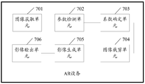
- FIG. 7 is a simplified functional block diagram of an AR device disclosed in an embodiment of the apparatus of the present invention.
- FIG. 1 is a system architecture diagram of a mobile vehicle communication system according to an embodiment of the present invention.
- the communication system 10 includes a vehicle 12, one or more wireless carrier systems 14, and a ground.
- the surface communication network 16, the computer 18, and the call center 20 are not specifically limited to the operating environments shown herein.
- the architecture, construction, setup, and operation of system 10, as well as its individual components, are generally known in the art. Thus, the following paragraphs simply provide an overview of an example communication system 10, and other systems not shown herein can also use the disclosed methods.
- the vehicle 12 can be implemented on a car or in the form of a car.
- the example system can also be implemented on other vehicles or in the form of other vehicles, such as cars, trucks, motorcycles, buses, boats, airplanes, helicopters, lawn mowers, snow shovels, recreational vehicles, amusement park vehicles.
- Other equipment such as agricultural equipment, construction equipment, trams, golf carts, trains and trams.
- the robotic device can also be used to perform the methods and systems described herein.
- vehicle electronics 28 include an information communication unit 30, a microphone 32, one or more buttons or other control inputs 34, an audio system 36, a visual display 38, and a GPS (Global Position System, global).
- a positioning system) module 40 and a plurality of VSMs (Vehicle Security Modules) 42 are provided. Some of these devices can be directly connected to an information communication unit, such as microphone 32 and button 34, while others use one or more network connections to make an indirect connection, such as communication bus 44 or entertainment bus 46.
- Suitable network connections include CAN (Controller Area Network), MOST (Media Oriented Systems Transport), LIN (Local Interconnect Network), LAN (Local Area Network) And other suitable connections, such as Ethernet or conforming to the known ISO (International Organization for Standardization), SAE (Society of Automotive Engineers), and IEEE (Institute of Electrical and Electronics Engineers, International) The Institute of Electrical and Electronics Engineers) other connections to standards and regulations, just to name a few.
- the information communication unit 30 may be an OEM (Original Equipment Manufacturer) installation (embedded) or accessory market device installed in the vehicle and capable of wirelessly sounding and/or wirelessly on the wireless carrier system 14 and/or Or data communication. This enables the vehicle to communicate with the call center 20, other information-enabled vehicles, or some other entity or device.
- the information communication unit preferably uses radio broadcasts to establish a communication channel with the wireless carrier system 14. (A voice channel and/or a data channel) enabling sound and/or data transmission to be transmitted and received on the channel.
- the messaging unit 30 enables the vehicle to provide a variety of different services, including those associated with navigation, telephony, emergency, diagnostics, infotainment, and the like.
- Data can be transmitted over a data connection (e.g., via packet data over a data channel, or via a voice channel using techniques known in the art).
- voice communication e.g., having a live advisor live advisor or voice response unit at call center 20
- data communication e.g, providing GPS location data or vehicle diagnostic data to call center 20
- SMS short message service
- SMS can be used to send and receive data (eg, PDP (Packet Data Protocol); the information communication unit can be configured to be mobile terminated and/or initiated, or configured to terminate and/or apply. initiate.
- the information communication unit 30 utilizes cellular communication according to GSM (Global System for Mobile Communication) or CDMA (Code Division Multiple Access) standards, and thus includes standards for voice communication (for example, hands-free calling).
- GSM Global System for Mobile Communication
- CDMA Code Division Multiple Access
- the modem can be implemented by software stored in the information communication unit and executed by the processor 52, or it can be a separate hardware component located inside or outside the information communication unit 30.
- the modem can use any number of different standards or protocols (eg EVDO (CDMA2000 1xEV-DO, EVDO), CDMA, GPRS (General Packet Radio Service) and EDGE (Enhanced Data Rate for GSM Evolution) GSM evolution technology)) to run.
- Wireless networking between the vehicle and other networked devices can also be performed using the information communication unit 30.
- the information communication unit 30 can be configured to wirelessly communicate according to one or more wireless protocols (eg, IEEE 802.11 protocol, WiMAX (Worldwide Interoperability for Microwave Access), or Bluetooth) .
- the information communication unit can be configured to have a static IP address, or can be set to be from the network.
- Another device such as a router or automatically receives the assigned IP address from a network address server.
- the processor 52 can be any type of device capable of processing electronic instructions, including a microprocessor, a microcontroller, a host processor, a controller, a vehicle communication processor, and an ASIC (Application Specific Integrated Circuit). . It can be a dedicated processor for the information communication unit 30 only or can be shared with other vehicle systems. Processor 52 executes various types of digital storage instructions, such as software or firmware programs stored in memory 54, which enables the information communication unit to provide a wide variety of services. For example, processor 52 can execute a program or process data to perform at least a portion of the methods discussed herein.
- the information communication unit 30 can be used to provide a range of vehicle services, including wireless communication to and/or from a vehicle.
- vehicle services include: turn-by-turn direct 1ns and other navigation-related services provided in conjunction with the GPS-based vehicle navigation module 40; airbag deployment notifications and interface modules with one or more collision sensors (eg, subjects) Control module (not shown) in combination with other emergency or roadside assistance associated services; diagnostic reports using one or more diagnostic modules; and infotainment related services, including music, web pages, movies, TV shows The video game and/or other information is downloaded by the infotainment module and stored for current or later playback.
- modules can be implemented in the form of software instructions stored inside or outside of the information communication unit 30, which may be hardware components located inside or outside the information communication unit 30, or they may be integrated with each other. / or shared, or integrated and / or shared with other systems located throughout the vehicle, just to name a few possibilities.
- the modules are implemented as VSMs 42 located external to the information communication unit 30, they may utilize the vehicle bus 44 to exchange data and commands with the information communication unit.
- the GPS module 40 receives radio signals from the constellation 60 of the GPS satellites. From these signals, the module 40 is able to determine the location of the vehicle that is used to provide the vehicle driver with navigation and other location-associated services.
- the navigation information can be presented on display 38 (or other display within the vehicle) or can be rendered in a language, such as when providing steering navigation.
- a navigation module (which may be part of the GPS module 40) within the dedicated vehicle can be used to provide navigation services, or some or all of the navigation services can be completed via the information communication unit 30, where the location information is sent to a remote location to facilitate Provide navigation maps, map annotations for vehicles (points of interest, Restaurants, etc.), route calculations, etc.
- the location information can be provided to call center 20 or other remote computer system, such as computer 18, for other purposes, such as fleet management. And, new or updated map data can be downloaded from the call center 20 to the GPS module 40 via the information communication unit 30.
- the vehicle 12 can include other vehicle system modules VSM 42 in the form of electronic hardware components that are located throughout the vehicle, typically receiving input from one or more sensors, The sensed inputs are used to perform diagnostics, monitoring, control, reporting, and/or other functions.
- VSMs 42 are preferably connected to other VSMs via a communication bus 44, also to the information communication unit 30, and can be programmed to run vehicle system and subsystem diagnostic tests.
- one VSM 42 can be an ECM (Engine Control Module) that controls various aspects of engine operation (eg, fuel ignition and ignition timing), and the other VSM 42 can be one or more that regulates the powertrain of the vehicle.
- ECM Engine Control Module
- the operating powertrain control module of the component, and the other VSM 42 can be a body control module that manages various electrical components (like the electric door lock and headlights of the vehicle) located throughout the vehicle.
- the engine control module is equipped with an OBD (On Board Diagnostics) feature that provides a large amount of real-time data, such as data received from various sensors (including vehicle emission sensors), and provides a standardized series. Diagnostic Trouble Code (DTS), which diagnoses fault codes allows technicians to quickly identify and repair faults within the vehicle.
- OBD On Board Diagnostics
- DTS Diagnostic Trouble Code
- the VSMs mentioned above are merely examples of some of the modules that may be used within the vehicle 12, and many other modules are also possible.
- the vehicle electronics 28 also includes a plurality of vehicle user interfaces that provide vehicle occupants with means for providing and/or receiving information, including a microphone 32, buttons 34, an audio system 36, and a visual display 38.
- vehicle user interface broadly includes any suitable form of electronic device, including hardware and software components that are located on a vehicle and that enable the vehicle user to communicate with components of the vehicle. Or communicate through the components of the vehicle.
- the microphone 32 provides an audio input to the information communication unit to enable the driver or other occupant to provide voice commands and perform an hands-free escort via the wireless carrier system 14. For this purpose, it can be connected to an in-vehicle automated sound processing unit that utilizes HMI (Human Machine Interface) technology known in the art.
- HMI Human Machine Interface
- the communication unit 30 is to initiate a wireless telephone call and provide other data, response or control inputs. Separate buttons can be used to initiate an emergency call as well as a regular service call to call center 20.
- the audio system 36 provides audio output to the vehicle occupant and can be a dedicated stand-alone system or part of the host vehicle audio system. In accordance with the particular embodiment illustrated herein, audio system 36 is operatively coupled to vehicle bus 44 and entertainment bus 46, and is capable of providing AM (Amplitude Modulation), FM (Frequency Modulation), and satellite broadcast, DVD. (Digital Versatile Disc) and other multimedia features. This functionality can be provided in conjunction with or separately from the infotainment module described above.
- Visual display 38 is preferably a graphical display, such as a touch screen on a dashboard or a heads-up display that is reflected from a windshield, and can be used to provide a variety of input and output functions.
- a graphical display such as a touch screen on a dashboard or a heads-up display that is reflected from a windshield
- Various other vehicle user interfaces can also be utilized, as the interface in Figure 1 is merely an example of a particular implementation.
- the wireless carrier system 14 is preferably a cellular telephone system comprising a plurality of cellular towers 70 (only one shown), one or more MSCs (Mobile Switching Centers) 72, and a wireless carrier system 14 coupled to the terrestrial network 16. Any other networking components required.
- Each of the cellular towers 70 includes transmit and receive antennas and base stations, and base stations from different cellular towers are directly connected to the MSC 72 or to the MSC 72 via intermediate devices (e.g., base station controllers).
- Cellular system 14 may implement any suitable communication technology including, for example, analog technologies (e.g., AMPS (Advanced Mobile Phone System)) or newer digital technologies (e.g., CDMA (e.g., CDMA2000) or GSM/GPRS).
- each base station and the cellular tower can be co-located at the same location, or they can be located farther from each other, each base station can respond to a single cellular tower or a single base station can serve each cellular tower, and each base station can be coupled to a single MSC, which is merely an example Give a small set of possible settings.
- different wireless carrier systems in the form of satellite communications can be used to provide one-way or two-way communication with the vehicle. This can be done using one or more communication satellites 62 and an uplink transmitting station 64.
- the one-way communication can be, for example, a satellite broadcast service in which program content (news, music, etc.) is received by the transmitting station 64, packaged for uploading, and then transmitted to the satellite 62, which broadcasts the program to the user.
- Two-way communication can be, for example, using satellite 62 at vehicle 12 and station 64 satellite telephone service for relay telephone communication between 64. If used, such a satellite phone can be attached to or used in place of the wireless carrier system 14.
- the terrestrial network 16 may be a conventional land-based radio communication network that is coupled to one or more fixed telephones and that connects the wireless carrier system 14 to the call center 20.
- terrestrial network 16 may include a PSTN (Public Switched Telephone Network), such as a PSTN that is used to provide wired telephone, packet switched data communications, and Internet infrastructure.
- PSTN Public Switched Telephone Network
- One or more portions of terrestrial network 16 can utilize standard wired networks, fiber optic or other optical networks, cable networks, power lines, other wireless networks (such as WLAN (Wireless Local Area Networks), or provide BWA (Broadband) Wireless Access, broadband wireless access) networks and any combination of them to implement.
- WLAN Wireless Local Area Networks
- BWA Broadband
- the terrestrial network 16 may also include one or more SMSCs (Short Message Service Centers) for storing, uploading, converting, and/or transmitting SMS (Short Message Service) between the sender and the receiver. ).
- SMSC Short Message Service Centers
- the SMSC can receive an SMS message from the call center 20 or a content provider (eg, an external short message entity or ESME), and the SMSC can transmit the SMS message to the vehicle 12 (eg, a mobile terminal device). SMSCs and their functions are known to the skilled person.
- call center 20 need not be connected via terrestrial network 16, but may include a wireless telephone device such that it can communicate directly with a wireless network (e.g., wireless carrier system 14).
- Computer 18 can be one of a plurality of computers that are accessible via a private or public network, such as the Internet. Each such computer 18 can be used for one or more purposes, such as a vehicle that can access a web server via the information communication unit 30 and the wireless carrier 14. Other such accessible computers 18 can be, for example, a service center computer in which diagnostic information and other vehicle data can be uploaded from the vehicle via the information communication unit 30; the vehicle owner or other user is a client for use, for example, for the following purposes Computer: accessing or receiving vehicle data, or setting or configuring user parameters, or controlling the functionality of the vehicle; or third party library, whether by communicating with the vehicle 12 or the call center 20, or communicating with both, vehicle data Or other information is provided to or from the third party library.
- a service center computer in which diagnostic information and other vehicle data can be uploaded from the vehicle via the information communication unit 30
- the vehicle owner or other user is a client for use, for example, for the following purposes Computer: accessing or receiving vehicle data, or setting or configuring user parameters, or controlling the functionality of
- the computer 18 can also be used to provide an Internet connection, such as a DNS (Domain Name Server) service, or as an IP using a DHCP (Dynamic Host Configuration Protocol) or other suitable protocol.
- DNS Domain Name Server
- DHCP Dynamic Host Configuration Protocol
- the address is given to the network address server of the vehicle 12.
- the call center 20 is designed to provide a variety of different system backend functions to the vehicle electronics 28, and according to the exemplary embodiment shown herein, the call center 20 typically includes one or more switches 80, servers 82, databases 84. On-site consultant 86, and VRS (Automatic voice response system) 88, all of which are known in the prior art. These various call center components are preferably coupled to each other via a wired or wireless local area network 90.
- Switch 80 can be a PBX (Private Branch Exchange) that routes incoming signals such that voice transmissions are typically sent to field consultant 86 via a regular telephone or to automated voice response system 88 using VoIP.
- the on-site consultant phone can also use VoIP (Voice over Internet Phone), as indicated by the dotted line in FIG.
- VoIP and other data communications through switch 80 are implemented via a modem (not shown) connected between switch 80 and network 90.
- Data transfer is passed to server 82 and/or database 84 via a modem.
- the database 84 is capable of storing account information such as user authentication information, vehicle identifiers, data profile records, behavioral patterns, and other related user information.
- Data transmission can also be performed by a wireless system, such as 802.1lx, GPRS, and the like.
- SMS short message service
- PDP public data packet data
- call center 20 can be configured to terminate and/or initiate mobile, or configured to terminate and/or initiate applications.
- the call center can instead use VRS 88 as an automated consultant, or VRS 88 and on-site consultants.
- a combination of 86 can be used.
- FIG. 1.1 is a functional block diagram of an exemplary vehicle 100 according to an embodiment of the present invention.
- Components coupled to or included in vehicle 100 may include propulsion system 102, sensor system 104, control system 106, peripherals 108, power source 110, computing device 111, and user interface 112.
- Computing device 111 can include a processor 113 and a memory 114.
- Computing device 111 may be part of a controller or controller of vehicle 100.
- the memory 114 can include instructions 115 that the processor 113 can run, and can also store map data 116.
- the components of the vehicle 100 can be configured to operate in a manner interconnected with each other and/or with other components coupled to the various systems.
- power source 110 can provide power to all components of vehicle 100.
- Computing device 111 can be configured to receive data from, and control, propulsion system 102, sensor system 104, control system 106, and peripherals 108.
- Computing device 111 can be configured to be at a user interface A display of the image is generated on 112 and an input is received from user interface 112.
- vehicle 100 may include more, fewer, or different systems, and each system may include more, fewer, or different components.
- the systems and components shown may be combined or divided in any number of ways.
- the propulsion system 102 can be used to provide power motion to the vehicle 100.
- the propulsion system 102 includes an engine/engine 118, an energy source 120, a transmission 122, and a wheel/tire 124.
- Engine/engine 118 may be or include any combination of internal combustion engine, electric motor, steam engine, and Stirling engine. Other engines and engines are also possible.
- propulsion system 102 can include multiple types of engines and/or engines.
- a gas-electric hybrid car may include a gasoline engine and an electric motor. Other examples are possible.
- Energy source 120 may be a source of energy that is fully or partially powered to engine/engine 118. That is, the engine/engine 118 can be used to convert the energy source 120 to mechanical energy. Examples of energy source 120 include gasoline, diesel, other petroleum-based fuels, propane, other compressed gas based fuels, ethanol, solar panels, batteries, and other sources of electrical power. The energy source(s) 120 may additionally or alternatively include any combination of fuel tanks, batteries, capacitors, and/or flywheels. In some examples, energy source 120 may also provide energy to other systems of vehicle 100.
- Transmission 122 can be used to transfer mechanical power from engine/engine 118 to wheel/tire 124.
- the transmission 122 can include a gearbox, a clutch, a differential, a drive shaft, and/or other components.
- the drive shaft includes one or more shafts for coupling to the wheel/tire 124.
- the wheel/tire 124 of the vehicle 100 can be configured in a variety of forms, including a single wheeled vehicle, a bicycle/motorcycle, a tricycle, or a car/truck four wheel form. Other wheel/tire forms are also possible, such as those that include six or more wheels.
- the wheel/tire 124 of the vehicle 100 can be configured to rotate differentially relative to the other wheels/tires 124.
- the wheel/tire 124 can include at least one wheel that is fixedly attached to the transmission 122 and at least one tire that is coupled to the driving surface and that is coupled to the edge of the wheel.
- Wheel/tire 124 may comprise any combination of metal and rubber, or a combination of other materials.
- Propulsion system 102 may additionally or alternatively include components in addition to those shown.
- Sensor system 104 may include several for sensing information about the environment in which vehicle 100 is located Sensors. As shown, the sensors of the sensor system include a GPS 126, an IMU (Inertial Measurement Unit) 128, a Radio Detection and Radar Ranging (RADAR) unit 130, a Laser Ranging (LIDAR) unit 132, a camera 134, and Actuator 136 to modify the position and/or orientation of the sensor. Sensor system 104 may also include additional sensors including, for example, sensors that monitor the internal systems of vehicle 100 (eg, O2 monitors, fuel gauges, oil temperatures, etc.). Sensor system 104 may also include other sensors.
- IMU Inertial Measurement Unit
- RADAR Radio Detection and Radar Ranging
- LIDAR Laser Ranging
- Actuator 136 to modify the position and/or orientation of the sensor.
- Sensor system 104 may also include additional sensors including, for example, sensors that monitor the internal systems of vehicle 100 (eg, O2 monitors, fuel gauges, oil temperatures,
- the GPS module 126 can be any sensor for estimating the geographic location of the vehicle 100.
- the GPS module 126 may include a transceiver that estimates the position of the vehicle 100 relative to the earth based on satellite positioning data.
- computing device 111 can be used in conjunction with map data 116 to use GPS module 126 to estimate the location of a lane boundary on a road on which vehicle 100 can travel.
- the GPS module 126 can take other forms as well.
- the IMU 128 may be used to sense changes in position and orientation of the vehicle 100 based on inertial acceleration and any combination thereof.
- the combination of sensors can include, for example, an accelerometer and a gyroscope. Other combinations of sensors are also possible.
- the RADAR unit 130 can be viewed as an object detection system for detecting the characteristics of an object using radio waves, such as the distance, height, direction or speed of the object.
- the RADAR unit 130 can be configured to transmit radio waves or microwave pulses that can bounce off any object in the course of the wave.
- the object may return a portion of the energy of the wave to a receiver (eg, a dish or antenna), which may also be part of the RADAR unit 130.
- the RADAR unit 130 can also be configured to perform digital signal processing on the received signal (bounce from the object) and can be configured to identify the object.
- LIDAR Light Detection and Ranging
- the LIDAR unit 132 includes a sensor that uses light to sense or detect objects in the environment in which the vehicle 100 is located.
- LIDAR is an optical remote sensing technique that can measure the distance to a target or other attribute of a target by illuminating the target with light.
- LIDAR unit 132 can include a laser source and/or a laser scanner configured to emit laser pulses, and a detector for receiving reflections of the laser pulses.
- the LIDAR unit 132 can include a laser range finder that is reflected by a rotating mirror and scans the laser around the digitized scene in one or two dimensions to acquire distance measurements at specified angular intervals.
- the LIDAR unit 132 can include components such as light (eg, laser) sources, scanners and optical systems, photodetectors, and receiver electronics, as well as position and navigation systems.
- the LIDAR unit 132 can be configured to image an object using ultraviolet (UV), visible, or infrared light, and can be used for a wide range of targets, including non-metallic objects.
- a narrow laser beam can be used to map physical features of an object with high resolution.
- wavelengths in the range of from about 10 microns (infrared) to about 250 nanometers (UV) can be used.
- Light is typically reflected via backscattering.
- Different types of scattering are used for different LIDAR applications such as Rayleigh scattering, Mie scattering and Raman scattering, and fluorescence.
- LIDAR can thus be referred to as Rayleigh laser RADAR, Mie LIDAR, Raman LIDAR, and sodium/iron/potassium fluorescent LIDAR.
- Appropriate combinations of wavelengths may allow remote mapping of objects, for example by looking for wavelength dependent changes in the intensity of the reflected signal.
- Three-dimensional (3D) imaging can be achieved using both a scanned LIDAR system and a non-scanning LIDAR system.
- "3D gated viewing laser radar” is an example of a non-scanning laser ranging system that uses a pulsed laser and a fast gating camera.
- the imaging LIDAR can also use a high-speed detector array that is typically built on a single chip using CMOS (Complementary Metal Oxide Semiconductor) and CCD (Charge Coupled Device) manufacturing techniques. And modulating the sensitive detector array to perform.
- CMOS Complementary Metal Oxide Semiconductor
- CCD Charge Coupled Device
- each pixel can be locally processed by high speed demodulation or gating such that the array can be processed to represent an image from the camera.
- thousands of pixels can be acquired simultaneously to create a 3D point cloud representing the object or scene detected by the LIDAR unit 132.
- a point cloud can include a set of vertices in a 3D coordinate system. These vertices may be defined, for example, by X, Y, Z coordinates and may represent the outer surface of the object.
- the LIDAR unit 132 can be configured to create a point cloud by measuring a large number of points on the surface of the object, and can output the point cloud as a data file. As a result of the 3D scanning process of the object through the LIDAR unit 132, the point cloud can be used to identify and visualize the object.
- the point cloud can be rendered directly to visualize the object.
- a point cloud may be converted to a polygonal or triangular mesh model by a process that may be referred to as surface reconstruction.
- Example techniques for converting a point cloud to a 3D surface may include a Delaunay triangulation, an alpha shape, and a rotating sphere. These techniques include building a network of triangles on existing vertices of a point cloud. Other example techniques may include points The cloud is converted to a volumetric distance field, and the implicit surface thus defined is reconstructed by a moving cube algorithm.
- Camera 134 can be used to capture any camera (eg, a still camera, video camera, etc.) of an image of the environment in which vehicle 100 is located. To this end, the camera can be configured to detect visible light, or can be configured to detect light from other portions of the spectrum, such as infrared or ultraviolet light. Other types of cameras are also possible. Camera 134 can be a two-dimensional detector or can have a three-dimensional spatial extent. In some examples, camera 134 can be, for example, a distance detector configured to generate a two-dimensional image indicative of the distance from camera 134 to several points in the environment. To this end, camera 134 can use one or more distance detection techniques.
- a distance detector configured to generate a two-dimensional image indicative of the distance from camera 134 to several points in the environment. To this end, camera 134 can use one or more distance detection techniques.
- camera 134 can be configured to use structured light technology in which vehicle 100 illuminates an object in the environment with a predetermined light pattern, such as a grid or checkerboard pattern, and uses camera 134 to detect reflections from predetermined light patterns of the object. . Based on the distortion in the reflected light pattern, the vehicle 100 can be configured to detect the distance of a point on the object.
- the predetermined light pattern may include infrared light or light of other wavelengths.
- Actuator 136 can be configured, for example, to modify the position and/or orientation of the sensor.
- Sensor system 104 may additionally or alternatively include components in addition to those shown.
- Control system 106 can be configured to control the operation of vehicle 100 and its components. To this end, control system 106 can include steering unit 138, throttle 140, braking unit 142, sensor fusion algorithm 144, computer vision system 146, navigation or routing system 148, and obstacle avoidance system 150.
- Steering unit 138 may be any combination of mechanisms configured to adjust the direction or direction of advancement of vehicle 100.
- the throttle 140 may be any combination of mechanisms configured to control the operating speed and acceleration of the engine/engine 118 and thereby control the speed and acceleration of the vehicle 100.
- Brake unit 142 may be any combination of mechanisms configured to decelerate vehicle 100.
- the brake unit 142 can use friction to slow the wheel/tire 124.
- the braking unit 142 can be configured to regeneratively convert the kinetic energy of the wheel/tire 124 into a current.
- Brake unit 142 can take other forms as well.
- Sensor fusion algorithm 144 may include, for example, an algorithm (or a computer program product that stores the algorithm) that computing device 111 may operate. Sensor fusion algorithm 144 can be configured to accept data from sensor 104 as an input. The data may include, for example, data representing information sensed at the sensors of sensor system 104. Sensor fusion algorithm 144 may include, for example, a Kalman filter, a Bayesian network, or Additional algorithms. Sensor fusion algorithm 144 may also be configured to provide various ratings based on data from sensor system 104, including, for example, an assessment of individual objects and/or features in the environment in which vehicle 100 is located, an assessment of a particular situation, and/or An assessment based on the likely impact of a particular situation. Other evaluations are also possible.
- Computer vision system 146 may be any system configured to process and analyze images captured by camera 134 to identify objects and/or features in the environment in which vehicle 100 is located, such as lane information, traffic, for example Signals and obstacles. To this end, computer vision system 146 may use object recognition algorithms, Structure from Motion (SFM) algorithms, video tracking, or other computer vision techniques. In some examples, computer vision system 146 may additionally be configured as a mapping environment, following an object, estimating the speed of an object, and the like.
- SFM Structure from Motion
- the navigation and route control system 148 can be any system configured to determine the driving route of the vehicle 100.
- the navigation and route control system 148 can additionally be configured to dynamically update the driving route while the vehicle 100 is in operation.
- navigation and route control system 148 can be configured to combine data from sensor fusion algorithm 144, GPS module 126, and one or more predetermined maps to determine a driving route for vehicle 100.
- the obstacle avoidance system 150 can be any system configured to identify, evaluate, and avoid or otherwise cross obstacles in the environment in which the vehicle 100 is located.
- Control system 106 may additionally or alternatively include components in addition to those shown.
- Peripheral device 108 can be configured to allow vehicle 100 to interact with external sensors, other vehicles, and/or users.
- peripheral device 108 can include, for example, wireless communication system 152, touch screen 154, microphone 156, and/or speaker 158.
- Wireless communication system 152 can be any system configured to be wirelessly coupled to one or more other vehicles, sensors, or other entities, either directly or via a communication network.
- the wireless communication system 152 can include an antenna and chipset for communicating with other vehicles, sensors, or other entities, either directly or through an air interface.
- the chipset or the entire wireless communication system 152 can be arranged to communicate in accordance with one or more other types of wireless communications (e.g., protocols) such as those described in Bluetooth, IEEE 802.11 (including any IEEE 802.11 revision).
- Wireless communication system 152 can take other forms as well.
- cellular technologies such as GSM, CDMA, UMTS (Universal Mobile Telecommunications System), EV-DO, WiMAX or LTE (Long Term Evolution), Zigbee, DSRC (Dedicated Short Range Communications), and RFID (Radio Frequency Identification) communication, and the like.
- Wireless communication system 152 can take other forms as well.
- Touch screen 154 can be used by a user to enter commands into vehicle 100.
- the touch screen 154 can be configured to sense at least one of a position and a movement of a user's finger via a capacitive sensing, a resistive sensing, or a surface acoustic wave process or the like.
- the touch screen 154 may be capable of sensing finger movement in a direction parallel to the touch screen surface or in the same plane as the touch screen surface, in a direction perpendicular to the touch screen surface, or in both directions, and may also be capable of sensing application to The level of pressure on the surface of the touch screen.
- Touch screen 154 may be formed from one or more translucent or transparent insulating layers and one or more translucent or transparent conductive layers. Touch screen 154 can take other forms as well.
- the microphone 156 can be configured to receive audio (eg, a voice command or other audio input) from a user of the vehicle 100.
- the speaker 158 can be configured to output audio to a user of the vehicle 100.
- Peripheral device 108 may additionally or alternatively include components in addition to those shown.
- the power source 110 can be configured to provide power to some or all of the components of the vehicle 100.
- the power source 110 can include, for example, a rechargeable lithium ion or lead acid battery.
- one or more battery packs can be configured to provide power.
- Other power materials and configurations are also possible.
- power source 110 and energy source 120 can be implemented together, as in some all-electric vehicles.
- Processor 113 included in computing device 111 may include one or more general purpose processors and/or one or more special purpose processors (eg, image processors, digital signal processors, etc.). Insofar as the processor 113 includes more than one processor, such processors can work individually or in combination. Computing device 111 may implement the function of controlling vehicle 100 based on input received through user interface 112.
- processors 113 may include one or more general purpose processors and/or one or more special purpose processors (eg, image processors, digital signal processors, etc.). Insofar as the processor 113 includes more than one processor, such processors can work individually or in combination.
- Computing device 111 may implement the function of controlling vehicle 100 based on input received through user interface 112.
- the memory 114 can include one or more volatile storage components and/or one or more non-volatile storage components, such as optical, magnetic, and/or organic storage devices, and the memory 114 can be fully or partially coupled to the processor 113. integrated.
- Memory 114 may include instructions 115 (eg, program logic) executable by processor 113 to perform various vehicle functions, including any of the functions or methods described herein.
- the components of the vehicle 100 can be configured to operate in a manner interconnected with other components internal and/or external to their respective systems. To this end, the components and systems of the vehicle 100 may be through a system bus, network, and/or Other connection mechanisms are communicatively linked together.
- FIG. 1.2 is a schematic diagram of an application scenario of an AR device, including an AR device 100, a driver in a cab, and a car.
- the AR device 100 is disposed between the front windshield 200 of the automobile and the driver, the device viewing plane of the AR device 100 is lower than the driver's viewing plane, and the AR device is disposed on the center console of the automobile.
- FIG. 2 is a schematic structural diagram of an AR device 100 according to an embodiment of the present invention.
- the AR device 100 includes a processor 101 that can couple one or more storage media.
- the storage medium includes a storage medium 111 and at least one memory 102.
- the storage medium 111 can be read-only, such as a read-only memory (ROM), or a readable/writable hard disk or flash memory.
- the memory 102 can be, for example, a random access memory (RAM).
- the memory 102 can be combined with the processor 101, or integrated into the processor 101, or composed of one independent unit or multiple units.
- the processor 101 is a control center of the AR device 100, and specifically provides time series and process equipment for executing instructions, completing interrupt events, providing time functions, and other functions.
- the processor 101 includes one or more central processing unit CPUs, such as CPU0 and CPU1 in FIG.
- the AR device 100 may further include multiple processors, such as the processor 101 and the processor 112 described in FIG. 2.
- Each processor can be single core or multiple cores.
- a particular implementation of a processor or memory described herein includes a general purpose component or a special purpose component that is configured to perform a task at a particular time, the specialized component being produced for performing a dedicated task.
- the processor described in the embodiments of the present invention includes at least one electronic device, circuitry, and/or processor chip configured to process data, such as computer program instructions. Program code executed by the processor 101, and/or the processor 112, or a single CPU of the processor 101 and/or the processor 112 may be stored in the memory 102 or the In the storage medium 111.
- the AR device 100 further includes a front camera 103, a front range finder 104, a rear camera 105, a rear range finder 106, and an output module 107 (such as an optical projector or a laser projector). And/or communication interface 108.
- the front camera 103, the front range finder 104, the rear camera 105, the rear range finder 106, and the output module 107 are coupled to the processor 101.
- the AR device 100 may further include a receiving/transmitting circuit 109 and an antenna 110. The receiving/transmitting circuit 109 and the antenna 110 are used to implement connection of an AR device to an external network.
- the constituent units of the AR device 100 may be coupled to each other through a communication bus, and the communication bus includes at least one of the following: a data bus, an address bus, a control bus, an expansion bus, and a local bus.
- the AR device 100 is only an exemplary physical device configuration disclosed in the embodiment of the present invention. The specific embodiment of the present invention is not limited to the specific configuration of the AR device.
- the processor 101 of the AR device 100 can be coupled to the at least one memory 102, where the program code is pre-stored, and the program code specifically includes an image acquisition module, a parameter detection module, a coefficient determination module, an image cropping module, image generation module, an image display module, the memory 102 further stores a kernel module, the core module includes an operating system (e.g., WINDOWS TM, ANDROID TM, IOS TM, etc.).
- an operating system e.g., WINDOWS TM, ANDROID TM, IOS TM, etc.
- the processor 101 of the AR device 100 is configured to invoke the program code to perform the image information processing method disclosed in the embodiment of the present invention, and specifically includes the following steps:
- the processor 101 of the AR device 100 runs the image acquisition module stored in the memory 102 to acquire a first image including an image of the target object 300, wherein the AR device is disposed on a center console of the automobile, The target object 300 is located in front of the car;
- the processor 101 of the AR device 100 runs the parameter detecting module stored in the memory 102, and detects an environmental parameter of the AR device based on the first image;
- the processor 101 of the AR device 100 runs the coefficient determining module stored in the memory 102, and determines a cropping scale coefficient of the first image based on the environment parameter;
- the processor 101 of the AR device 100 runs the image cropping module stored in the memory 102, and crops the first image to obtain a second image based on the cropping scale coefficient;
- the processor 101 of the AR device 100 runs the image generation module stored in the memory 102, and extracts M contour feature points in the remaining images of the target object 300 in the second image to generate the target object.
- the M is a positive integer;
- the processor 101 of the AR device 100 runs the image display module stored in the memory 102, The AR image is displayed on the front windshield 200 of the automobile.
- the specific implementation manner of the processor 101 for displaying the AR image on the front windshield 200 of the automobile is: according to the position of the M contour feature points in the second image, Adding the AR image to the third image, the third image is a blank image, the size of the third image is matched with the size of the second image; based on the contour feature points in the AR image and the An environmental parameter determining a projection angle of the AR image; and projecting the third image on the front windshield 200 according to the projection angle.
- the AR device first acquires a first image including an image of the target object, detects an environmental parameter of the AR device based on the first image, and secondly, determines, by the AR device, the clipping of the first image based on the environmental parameter.
- the scaling factor again, the AR device crops the first image to obtain a second image based on the cropping scale factor, and the AR device then extracts M contour feature points in the remaining images of the target object in the second image to generate an AR image of the target object.
- the AR device displays the AR image on the front windshield of the car.
- the AR device provided by the embodiment of the present invention can generate an augmented reality AR image of the target object and display the generated AR image on the front windshield of the automobile, thereby facilitating the driver to comprehensively and clearly obtain the environmental dynamics in the line of sight, thereby Improve driving safety.
- the specific implementation manner of the processor 101 for displaying the AR image on the front windshield 200 of the automobile is: determining, according to the contour feature point in the AR image and the environment parameter, a projection angle of the AR image; the AR image is projected on the front windshield 200 according to the projection angle.
- the front windshield 200 includes a display screen
- the specific implementation manner of the processor 101 for displaying the AR image on the front windshield 200 of the automobile is: determining the M contour feature points. Corresponding positions of M projection points on the front windshield 200; displaying the AR image on the display screen of the front windshield 200 based on the positions of the M projection points, the front gear
- the windshield 200 is a display screen.
- the specific implementation manner of the processor 101 to acquire the first image of the image of the target object 300 is: taking the ranging feature point on the target object 300 as a focus reference point, and capturing the target object 300 to obtain the first An image, wherein a pixel point corresponding to the focus reference point in the first image is a focus of the first image.
- the processor 101 is configured to detect, according to the first image, an environment parameter of the AR device 100, based on: detecting a relative position of the focus in the first image in the first image. a distance c0 between the ranging feature point and a center point of the AR device 100, and determining an angle q0 between the line segment corresponding to the distance c0 and the device view plane, where the device view plane is the AR device 100 Equipment view plane;
- the processor 101 determines, according to the environment parameter, a specific implementation manner of the cropping scale coefficient of the first image, that is, the center point of the AR device 100 is represented as an origin O of the two-dimensional coordinate system XOY.
- a straight line passing through the ranging feature point of the target object 300 and perpendicular to the viewing plane of the device is represented as a straight line L, and the two-dimensional coordinate system XOY is determined based on the origin O and the straight line L.
- a reference plane the projection line of the device view plane on the reference plane is illustrated as an X axis, and the direction of the X axis is set to be a direction away from the line L by the origin O;
- a projection point of the driver's human eye center point on the reference plane is illustrated as a point A in the two-dimensional coordinate system XOY, and a projection point of the feature point B′ on the reference plane is indicated as a point B, and the feature point is The projection point of C' on the reference plane is indicated as point C, and the projection line of the driver's view plane on the reference plane is indicated as a straight line N;
- the projection of the point A on the X axis is a point A1
- the projection of the point B on the straight line N is a point B1
- the projection of the point B on the X axis is a point B2.
- the projection of the origin O on the straight line L is a point O1
- the projection of the point A on the straight line L is a point A2
- the intersection of the straight line where the line segment OB is located and the straight line L is a point C1
- the intersection of the straight line and the straight line L is point C2
- the length of the line segment OA is equivalent to the first distance c1
- the ⁇ AOA1 is equivalent to the angle q1
- the length of the line segment OB is equivalent to the distance c2
- ⁇ BOO1 is equivalent to The angle q2
- the length of the line segment OC is equivalent to the distance c3
- the ⁇ COO1 is equivalent to the angle q3;
- the expression of the straight line and the expression of the straight line L determine the coordinates of the point C2; the point C3 is determined according to the expression of the straight line passing through the point C and the origin O and the expression of the straight line L
- Coordinates of the point C1 are determined according to an expression of a straight line passing through the point B and the origin O and an expression of the straight line L; according to the point C1, the point C2, and the point C3
- the coordinates determine the cropping scale factor of the first image.
- FIG. 3 illustrates a method for processing image information according to a first method embodiment of the present invention. It should be noted that although the image information processing method disclosed in the embodiment of the present invention can be implemented based on the physical device of the AR device 100 shown in FIG. 2, the above-described example AR device 100 does not constitute the image information processing method disclosed in the method embodiment of the present invention. The only limit.
- the image information processing method includes the following steps:
- the augmented reality AR device acquires a first image that includes an image of a target object, where the AR device is disposed on a center console of the automobile, and the target object is located in front of the automobile;
- the AR device detects an environmental parameter of the AR device based on the first image.
- the AR device determines, according to the environment parameter, a cropping ratio coefficient of the first image.
- the AR device crops the first image to obtain a second image based on the cropping scale coefficient.
- the AR device extracts M contour feature points in the remaining images of the target object in the second image to generate an AR image of the target object, where the M is a positive integer;
- the AR device displays the AR image on a front windshield of the automobile.
- the AR device first acquires a first image including an image of the target object, detects an environmental parameter of the AR device based on the first image, and secondly, determines, by the AR device, the clipping of the first image based on the environmental parameter.
- the scaling factor again, the AR device crops the first image to obtain a second image based on the cropping scale factor, and the AR device then extracts M contour feature points in the remaining images of the target object in the second image to generate an AR image of the target object.
- the AR device displays the AR image on the front windshield of the car.
- the AR device provided by the embodiment of the present invention can generate an augmented reality AR image of the target object and display the generated AR image on the front windshield of the automobile, thereby facilitating the driver to comprehensively and clearly obtain the environmental dynamics in the line of sight, thereby Improve driving safety.
- FIG. 4 is a schematic flowchart of a method for processing image information disclosed in an embodiment of a second method of the present invention.
- the image information processing method specifically includes the following steps:
- the AR device takes a ranging feature point on the target object as a focus reference point, and captures the target object to obtain a first image, where a pixel corresponding to the focus reference point in the first image is The focus of the first image.
- the AR device may capture the target object through a front camera to obtain a first image.
- the AR device detects a distance c0 between the ranging feature point and a center point of the AR device based on a relative position of the focus in the first image in the first image, and determines the distance c0.
- the specific implementation manner in which the AR device detects the distance c0 between the ranging feature point and the center point of the AR device is:
- the AR device controls the pre-rangefinder of the AR device according to the first ranging reference angle q to detect a distance c0 between the ranging feature point and a center point of the AR device;
- the shooting angle range of the front camera includes a longitudinal shooting angle range and a horizontal shooting An angular range
- the AR device is capable of determining a longitudinal angle of the first ranging reference angle q according to a longitudinal relative position of the focus in the first image and a longitudinal shooting angle range of the front camera, according to the focus in the first image
- the lateral relative position, and the lateral shooting angle range of the front camera determine the lateral angle of the first ranging reference angle q; the longitudinal angle is the angle q0.
- the manner in which the AR device controls the front range finder may specifically include the following:
- the AR device controls the body of the range finder or the movable part to rotate; or
- the AR device changes the emission direction of the laser of the range finder by optical means.
- the direction of the laser is controlled by a mirror, and the direction of the mirror is changed to change the direction of the laser.
- the AR device captures a driver image to obtain a reference image, and detects a driver's human eye center point and the AR device based on a relative position of a driver's human eye center pixel in the reference image in the reference image. a first distance c1 between the center points, and determining an angle q1 between the line segment corresponding to the first distance c1 and the viewing plane of the device;
- the AR device may capture a driver image through a rear camera of the AR device to obtain a reference image, and detect a first distance c1 and an angle q1 by a rear range finder of the AR device.
- the detection process of the first distance c1 and the angle q1 is similar to the process of step S402, and details are not described herein again.
- the AR device detects a second distance c2 between a feature point B' of an upper edge of the front windshield and a center point of the AR device, a line segment corresponding to the second distance c2, and a view plane of the device.
- the initial ranging direction of the front range finder of the AR device is in the device view plane, and the lens shooting direction of the front camera of the AR device can be equivalent to the same direction; the AR device passes the front ranging
- the specific implementation manner of detecting the second distance c2, the angle q2, the third distance c3, and the angle q3 includes the following steps:
- the AR device controls the front range finder to perform ranging ranging from bottom to top, and obtains m distance parameters and angle parameters, where m is a positive integer greater than or equal to 4;
- the AR device determines that the kth distance parameter of the m distance parameters is a second distance c2, and the angle parameter corresponding to the kth distance parameter is an angle q2, the kth distance parameter and the k+1th Distance parameter The difference between the difference is greater than a preset distance threshold, and the kth distance parameter is greater than the k+1th distance parameter;
- the AR device determines that the nth distance parameter of the m distance parameters is a third distance c3, and the angle parameter corresponding to the nth distance parameter is an angle q3, the nth distance parameter and the n-1th The difference between the distance parameters is greater than a preset distance threshold, and the nth distance parameter is greater than the n-1th distance parameter.
- the AR device indicates that a center point of the AR device is an origin O of a two-dimensional coordinate system XOY, and a straight line passing through the ranging feature point of the target object and perpendicular to a plane of view of the device is indicated.
- a straight line L based on the origin O and the straight line L, determining a reference plane of the two-dimensional coordinate system XOY, indicating a projection line of the device view plane on the reference plane as an X-axis, and The direction of the X axis is set to be a direction away from the straight line L by the origin O;
- the AR device indicates a projection point of the driver's human eye center point on the reference plane as a point A in the two-dimensional coordinate system XOY, and a projection point of the feature point B' on the reference plane is indicated as Point B, the projection point of the feature point C' on the reference plane is indicated as point C, and the projection line of the driver's view plane on the reference plane is indicated as a straight line N;
- FIG. 4.1 is a schematic diagram of an equivalent two-dimensional coordinate system XOY of an exemplary application scenario disclosed in the embodiment of the present invention; wherein the projection of the point A on the X-axis is a point A1, the projection of the point B on the straight line N is a point B1, the projection of the point B on the X-axis is a point B2, and the projection of the origin O on the straight line L is a point O1,
- the projection of the point A on the straight line L is the point A2, the intersection of the straight line where the line segment OB is located and the straight line L is the point C1, and the intersection of the straight line where the line segment AB is located and the straight line L is the point C2, the line segment OC
- the intersection of the straight line and the straight line L is point C3;
- the AR device compares the length of the line segment OA to the first distance c1, the ⁇ AOA1 to the angle q1, and the length of the line segment OB to the distance c2.
- ⁇ BOO1 is equivalent to the angle q2
- the length of the line segment OC is equivalent to the distance c3
- ⁇ COO1 is equivalent to the angle q3;
- the AR device determines, according to the distance c0 and the angle q0, an expression of a length of the line segment OO1 and the straight line L; determining the point A according to the length of the line segment OA and the ⁇ AOA1
- the coordinates of the point B are determined according to the length of the line segment OB and the ⁇ BOO1; the coordinates of the point C are determined according to the length of the line segment OC and the ⁇ COO1;
- the expression of the straight line of A and the point B and the expression of the straight line L determine the coordinates of the point C2; the expression according to the straight line passing the point C and the origin O and the expression of the straight line L Determining the coordinates of the point C3; determining the coordinates of the point C1 according to the expression of the straight line passing the point B and the origin O and the expression of the straight line L; according to the point C1, the point C2 and coordinates of the point C3 determine a cropping scale coefficient of the first image;
- the AR device crops the first image to obtain a second image based on the cropping scale coefficient.
- the AR device extracts M contour feature points in the remaining images of the target object in the second image to generate an AR image of the target object, where the M is a positive integer;
- the AR device adds the AR image to a third image according to a position of the M contour feature points in the second image, where the third image is a blank image, and the third image is The size matches the size of the second image;
- the AR device determines a projection angle of the AR image based on a contour feature point in the AR image and the environment parameter.
- the specific implementation manner of determining the projection angle of the AR image by the AR device based on the contour feature point and the environment parameter in the AR image may include the following steps:
- FIG. 4.2 is a schematic diagram of a feature point on a target object corresponding to a contour feature point in a two-dimensional coordinate system XOY according to an embodiment of the present invention
- the AR device determines that the jth contour feature point of the M contour feature points is a current contour feature point T0, and the point on the target object corresponding to the current contour feature point T0 is a feature point T';
- the feature point T' on the target object is indicated as a point T on the straight line L, and the intersection of the line segment AT and the line segment BC is a projection point T1;
- the AR device projects the third image on the front windshield according to the projection angle.
- the driver's human eye can see the AR image displayed on the front windshield that matches the image of the target object, such as the target object being a wire in front of the car.
- the pole displays the contour image of the pole on the front windshield. This helps the driver to fully and clearly obtain the environmental dynamics in the line of sight and improve driving safety.
- the AR device can project the third image on the front windshield by an optical projector in the AR device.
- the AR device first acquires a first image including an image of the target object, detects an environmental parameter of the AR device based on the first image, and secondly, determines, by the AR device, the clipping of the first image based on the environmental parameter.
- the scaling factor again, the AR device crops the first image to obtain a second image based on the cropping scale factor, and the AR device then extracts M contour feature points in the remaining images of the target object in the second image to generate an AR image of the target object.
- the AR device displays the AR image on the front windshield of the car.
- the AR device provided by the embodiment of the present invention can generate an augmented reality AR image of the target object and display the generated AR image on the front windshield of the automobile, thereby facilitating the driver to comprehensively and clearly obtain the environmental dynamics in the line of sight, thereby Improve driving safety.
- FIG. 5 is a schematic flowchart of a method for processing image information according to a third method embodiment of the present invention.
- the image information processing method specifically includes the following steps:
- the AR device takes a ranging feature point on the target object as a focus reference point, and captures the target object to obtain a first image, where a pixel corresponding to the focus reference point in the first image is The focus of the first image.
- the AR device detects a distance c0 between the ranging feature point and a center point of the AR device based on a relative position of the focus in the first image in the first image, and determines the distance c0.
- the AR device captures a driver image to obtain a reference image, and detects a driver's human eye center based on a relative position of a driver's human eye center pixel in the reference image in the reference image. a first distance c1 between the point and the center point of the AR device, and determining an angle q1 between the line segment corresponding to the first distance c1 and the view plane of the device;
- the AR device detects a second distance c2 between a feature point B' of an upper edge of the front windshield and a center point of the AR device, a line segment corresponding to the second distance c2, and a view plane of the device.
- the AR device indicates a center point of the AR device as an origin O of the two-dimensional coordinate system XOY, and indicates a straight line passing through the ranging feature point of the target object and perpendicular to the view plane of the device.
- a straight line L based on the origin O and the straight line L, determining a reference plane of the two-dimensional coordinate system XOY, indicating a projection line of the device view plane on the reference plane as an X-axis, and The direction of the X axis is set to be a direction away from the straight line L by the origin O;
- the AR device indicates a projection point of the driver's human eye center point on the reference plane as a point A in the two-dimensional coordinate system XOY, and a projection point of the feature point B′ on the reference plane is indicated as Point B, the projection point of the feature point C' on the reference plane is indicated as point C, and the projection line of the driver's view plane on the reference plane is indicated as a straight line N;
- FIG. 4.1 wherein the projection of the point A on the X axis is a point A1, the projection of the point B on the straight line N is a point B1, and the point B is in the The projection on the X-axis is point B2, the projection of the origin O on the straight line L is a point O1, the projection of the point A on the straight line L is the point A2, the straight line where the line segment OB is located and the straight line
- the intersection of L is point C1, the intersection of the line where the line segment AB is located and the line L is point C2, and the intersection of the line where the line segment OC is located and the line L is point C3;
- the AR device compares the length of the line segment OA to the first distance c1, the ⁇ AOA1 to the angle q1, and the length of the line segment OB to the distance c2.
- ⁇ BOO1 is equivalent to the angle q2
- the length of the line segment OC is equivalent to the distance c3
- ⁇ COO1 is equivalent to the angle q3;
- the AR device determines, according to the distance c0 and the angle q0, an expression of a length of the line segment OO1 and the straight line L; determining the point A according to the length of the line segment OA and the ⁇ AOA1
- the coordinates of the point B are determined according to the length of the line segment OB and the ⁇ BOO1; the coordinates of the point C are determined according to the length of the line segment OC and the ⁇ COO1;
- the expression of the straight line of A and the point B and the expression of the straight line L determine the coordinates of the point C2; the expression according to the straight line passing the point C and the origin O and the expression of the straight line L Determining the coordinates of the point C3; determining the coordinates of the point C1 according to the expression of the straight line passing the point B and the origin O and the expression of the straight line L; according to the point C1, the point C2 and coordinates of the point C3 determine a cropping scale coefficient of the first image;
- the AR device crops the first image to obtain a second image based on the cropping scale coefficient.
- the AR device extracts M contour feature points in the remaining images of the target object in the second image to generate an AR image of the target object, where the M is a positive integer;
- the AR device determines a projection angle of the AR image based on a contour feature point in the AR image and the environment parameter.
- the specific implementation manner of determining the projection angle of the AR image by the AR device based on the contour feature point and the environment parameter in the AR image may include the following steps:
- the AR device determines that the jth contour feature point of the M contour feature points is a current contour feature point T0, and the point on the target object corresponding to the current contour feature point T0 is a feature point T';
- the AR device indicates a feature point T' on the target object as a point T on a straight line L, and an intersection of the line segment AT and the line segment BC is a projection point T1;
- the AR device determines the coordinates of the point T according to the position of the current contour feature point T0 in the second image, the correspondence between the line segment C2C3 and the second image;
- the AR device determines an expression of the line segment AT according to the coordinates of the point T and the coordinates of the point A;
- the AR device determines the coordinates of the projection point T1 according to the expression of the line segment AT and the expression of the line segment BC;
- the AR device calculates an angle q6 between the line segment OT1 and the X axis according to the coordinates of the projection point T1;
- the AR device determines that the angle q6 is a projection angle of the AR device
- the AR device projects the AR image on the front windshield according to the projection angle.
- the driver looks at the target object through the front windshield, the driver's eye can see the front windshield
- the AR image displayed on the glass conforms to the image of the target object. If the target object is a pair of electric poles in front of the car, the contour image of the utility pole is displayed on the front windshield, thus facilitating the driver's overall clarity. Get environmental dynamics within the line of sight and improve driving safety.
- the AR device can project the AR image on the front windshield by using a laser projector in the AR device.
- the AR device in the embodiment of the present invention can project the processed multiple AR images to the front windshield of the automobile at a time. Therefore, it is beneficial to improve the image processing efficiency of the AR device.
- the AR device first acquires a first image including an image of the target object, detects an environmental parameter of the AR device based on the first image, and secondly, determines, by the AR device, the clipping of the first image based on the environmental parameter.
- the scaling factor again, the AR device crops the first image to obtain a second image based on the cropping scale factor, and the AR device then extracts M contour feature points in the remaining images of the target object in the second image to generate an AR image of the target object.
- the AR device displays the AR image on the front windshield of the car.
- the AR device provided by the embodiment of the present invention can generate an augmented reality AR image of the target object and display the generated AR image on the front windshield of the automobile, thereby facilitating the driver to comprehensively and clearly obtain the environmental dynamics in the line of sight, thereby Improve driving safety.
- FIG. 6 is a schematic flowchart of a method for processing image information disclosed in a fourth method of the present invention.
- the image information processing method specifically includes the following steps:
- the AR device takes a ranging feature point on the target object as a focus reference point, and captures the target object to obtain a first image, wherein a pixel point corresponding to the focus reference point in the first image is a focus of the first image;
- the AR device detects a distance c0 between the ranging feature point and a center point of the AR device based on a relative position of the focus in the first image in the first image, and determines the distance c0.
- the AR device captures a driver image to obtain a reference image, and detects a driver's human eye center based on a relative position of a driver's human eye center pixel in the reference image in the reference image. a first distance c1 between the point and the center point of the AR device, and determining an angle q1 between the line segment corresponding to the first distance c1 and the view plane of the device;
- the AR device detects a second distance c2 between a feature point B' of an upper edge of the front windshield and a center point of the AR device, a line segment corresponding to the second distance c2, and a view plane of the device.
- the AR device indicates a center point of the AR device as an origin O of the two-dimensional coordinate system XOY, and indicates a straight line passing through the ranging feature point of the target object and perpendicular to a plane of view of the device.
- a straight line L based on the origin O and the straight line L, determining a reference plane of the two-dimensional coordinate system XOY, indicating a projection line of the device view plane on the reference plane as an X-axis, and The direction of the X axis is set to be a direction away from the straight line L by the origin O;
- the AR device indicates a projection point of the driver's human eye center point on the reference plane as a point A in the two-dimensional coordinate system XOY, and a projection point of the feature point B' on the reference plane is indicated as Point B, the projection point of the feature point C' on the reference plane is indicated as point C, and the projection line of the driver's view plane on the reference plane is indicated as a straight line N;
- FIG. 4.1 wherein the projection of the point A on the X axis is a point A1, the projection of the point B on the straight line N is a point B1, and the point B is in the The projection on the X-axis is point B2, the projection of the origin O on the straight line L is a point O1, the projection of the point A on the straight line L is the point A2, the straight line where the line segment OB is located and the straight line
- the intersection of L is point C1, the intersection of the line where the line segment AB is located and the line L is point C2, and the intersection of the line where the line segment OC is located and the line L is point C3;
- the AR device compares the length of the line segment OA to the first distance c1, the ⁇ AOA1 to the angle q1, and the length of the line segment OB to the distance c2.
- ⁇ BOO1 is equivalent to the angle q2
- the length of the line segment OC is equivalent to the distance c3
- ⁇ COO1 is equivalent to the angle q3;
- the AR device determines, according to the distance c0 and the angle q0, an expression of a length of the line segment OO1 and the straight line L; determining the point A according to the length of the line segment OA and the ⁇ AOA1
- the coordinates of the point B are determined according to the length of the line segment OB and the ⁇ BOO1; the coordinates of the point C are determined according to the length of the line segment OC and the ⁇ COO1;
- the expression of the straight line of A and the point B and the expression of the straight line L determine the coordinates of the point C2; the expression according to the straight line passing the point C and the origin O and the expression of the straight line L Determining the coordinates of the point C3; determining the coordinates of the point C1 according to the expression of the straight line passing the point B and the origin O and the expression of the straight line L; according to the point C1, the point C2 and coordinates of the point C3 determine a cropping scale coefficient of the first image;
- the AR device crops the first image to obtain a second image based on the cropping scale coefficient
- the AR device extracts M contour feature points in the remaining images of the target object in the second image to generate an AR image of the target object, where the M is a positive integer;
- the AR device determines positions of M projection points on the front windshield corresponding to the M contour feature points
- the specific implementation manner of determining, by the AR device, the positions of the M projection points on the front windshield corresponding to the M contour feature points is:
- the AR device determines that the jth contour feature point of the M contour feature points is a current contour feature point T0, and the point on the target object corresponding to the current contour feature point T0 is a feature point T';
- the AR device indicates a feature point T' on the target object as a point T on a straight line L, and an intersection of the line segment AT and the line segment BC is a projection point T1;
- the AR device determines the coordinates of the point T according to the position of the current contour feature point T0 in the second image, the correspondence between the line segment C2C3 and the second image;
- the AR device determines an expression of the line segment AT according to the coordinates of the point T and the coordinates of the point A;
- the AR device determines the coordinates of the projection point T1 according to the expression of the line segment AT and the expression of the line segment BC;
- the AR device adds the coordinates of the projection point T1 in the set of projection point positions, and saves a mapping relationship between the j-th contour feature point and the coordinates of the projection point T1;
- the AR device displays the AR image on a display screen of a front windshield of the automobile based on positions of the M projection points;
- the driver's human eye can see the AR image displayed on the front windshield that matches the image of the target object, such as the target object being a wire in front of the car.
- the pole displays the contour image of the pole on the front windshield. This helps the driver to fully and clearly obtain the environmental dynamics in the line of sight and improve driving safety.
- the AR device may transmit the AR image to the display screen in the front windshield through a communication interface of the AR device, and the position of the M projection points, thereby, the front windshield of the automobile The AR image is displayed on the top.
- the AR device first acquires a first image including an image of the target object, detects an environmental parameter of the AR device based on the first image, and secondly, determines, by the AR device, the clipping of the first image based on the environmental parameter.
- the scaling factor again, the AR device crops the first image to obtain a second image based on the cropping scale factor, and the AR device then extracts M contour feature points in the remaining images of the target object in the second image to generate an AR image of the target object.
- the AR device displays the AR image on the front windshield of the car.
- the AR device provided by the embodiment of the present invention can generate an augmented reality AR image of the target object and display the generated AR image on the front windshield of the automobile, thereby facilitating the driver to comprehensively and clearly obtain the environmental dynamics in the line of sight, thereby Improve driving safety.
- the steps performed in the foregoing AR device may be specifically implemented by the AR device by executing a software module (program code) in the above memory.
- the step S301, the step S401, the step S501, and the step S601 may be implemented by the AR device executing the image acquiring module shown in FIG. 2; the step S302, the step S402, the step S403, the step S404, the step S502, and the step S503.
- Step S504, step S602, step S603, and step S604 may be implemented by the AR device executing the parameter detecting module shown in FIG.
- the algorithm may be implemented by the AR device to perform the coefficient determination module shown in FIG. 2; the step S304, the step S409, the step S509, and the step S609 may be implemented by the AR device executing the image cropping module shown in FIG. 2, the step S305.
- Step S410, step S510, and step S610 may be implemented by the AR device executing the image generation module shown in FIG. 2, the step S306, the step S411 to the step S413.
- Step S511, step S512, and step S611, step S612 can be implemented by the AR device executing the image output module shown in FIG. 2.
- FIG. 7 is a simplified functional block diagram of an AR device disclosed in an embodiment of the apparatus of the present invention.
- the AR device includes an image obtaining unit 701, a parameter detecting unit 702, a coefficient determining unit 703, an image cropping unit 704, an image generating unit 705, and an image output unit 706, wherein:
- the image obtaining unit 701 is configured to acquire a first image that includes an image of a target object, where the AR device is disposed on a center console of the automobile, and the target object is located in front of the automobile;
- the parameter detecting unit 702 is configured to detect an environmental parameter of the AR device based on the first image
- the coefficient determining unit 703 is configured to determine a cropping scale coefficient of the first image based on the environment parameter
- the image cropping unit 704 is configured to crop the first image to obtain a second image based on the cropping scale coefficient
- the image generating unit 705 is configured to extract M contour feature points in the remaining images of the target object in the second image to generate an AR image of the target object, where the M is a positive integer;
- the image output unit 706 is configured to display the AR image on a front windshield of the automobile.
- the specific implementation manner that the image output unit 706 displays the AR image on the front windshield of the automobile is:
- the third image is a blank image, and the size of the third image is different from the second image
- the size of the image matches;
- the third image is projected on the front windshield according to the projection angle.
- the image output unit 706 displays the AR image on a front windshield of the automobile.
- the specific implementation of the image is:
- the AR image is projected on the front windshield according to the projection angle.
- the front windshield includes a display screen
- the specific implementation manner of the image output unit 706 for displaying the AR image on the front windshield of the automobile is:
- the AR image is displayed on a display screen of the front windshield of the automobile based on the positions of the M projection points.
- the image acquiring unit 701 is configured to acquire the first image of the image of the target object by using the ranging feature point on the target object as a focus reference point, and capturing the target object to obtain the first image.
- the pixel point corresponding to the focus reference point in the first image is a focus of the first image.
- the parameter detecting unit 702 is configured to: according to the first image, a specific implementation manner of detecting an environment parameter of the AR device:
- the coefficient determining unit 703 determines, according to the environment parameter, a specific implementation manner of the cropping scale coefficient of the first image is:
- a center point of the AR device as an origin O of the two-dimensional coordinate system XOY, and indicating a straight line passing through the ranging feature point of the target object and perpendicular to the viewing plane of the device as a straight line L, based on Describe the origin O and the straight line L, determine a reference plane of the two-dimensional coordinate system XOY, and indicate a projection line of the device view plane on the reference plane as an X-axis, and the direction of the X-axis is set to a direction away from the straight line L by the origin O;
- a projection point of the driver's human eye center point on the reference plane is illustrated as a point A in the two-dimensional coordinate system XOY, and a projection point of the feature point B′ on the reference plane is indicated as a point B, and the feature point is The projection point of C' on the reference plane is indicated as point C, and the projection line of the driver's view plane on the reference plane is indicated as a straight line N;
- the projection of the point A on the X axis is a point A1
- the projection of the point B on the straight line N is a point B1
- the projection of the point B on the X axis is a point B2.
- the projection of the origin O on the straight line L is a point O1
- the projection of the point A on the straight line L is a point A2
- the intersection of the straight line where the line segment OB is located and the straight line L is a point C1
- the intersection of the straight line and the straight line L is point C2
- the length of the line segment OA is equivalent to the first distance c1
- the ⁇ AOA1 is equivalent to the angle q1
- the length of the line segment OB is equivalent to the distance c2
- ⁇ BOO1 is equivalent to the An angle q2
- the length of the line segment OC is equivalent to the distance c3
- the ⁇ COO1 is equivalent to the angle q3;
- the expression of the straight line and the expression of the straight line L determine the coordinates of the point C2; the point C3 is determined according to the expression of the straight line passing through the point C and the origin O and the expression of the straight line L
- Coordinates of the point C1 are determined according to an expression of a straight line passing through the point B and the origin O and an expression of the straight line L; according to the point C1, the point C2, and the point C3
- the coordinates determine the cropping scale factor of the first image.
- the AR device described in the embodiment of the functional unit device of the present invention is presented in the form of a functional unit.
- the term "unit” as used herein shall be understood to mean the broadest possible meaning for Objects that implement the functions described for the various "units” may be, for example, an integrated circuit ASIC, a single circuit, a processor (shared, dedicated or chipset) and memory for executing one or more software or firmware programs, combinatorial logic circuits And/or provide other suitable components to perform the above functions.
- the hardware carrier of the AR device can be composed of the AR device 100 shown in FIG. 1.2 and FIG. 2 .
- the function of the image acquiring unit 701 may be implemented by the processor 101 and the memory 102 in the AR device 100, and specifically, the processor 100 is used to run the image acquiring module in the memory 102 to invoke the front camera 103. Obtaining a first image including an image of the target object;
- the function of the parameter detecting unit 702 may be implemented by the processor 101 and the memory 102 in the AR device 100, in particular, the processor 100 runs a parameter obtaining module in the memory 102, and detects an AR based on the first image.
- the processor 100 runs a parameter obtaining module in the memory 102, and detects an AR based on the first image.
- the function of the coefficient determining unit 703 may be implemented by the processor 101 and the memory 102 in the AR device 100, in particular, the processor 100 runs a coefficient determining module in the memory 102, and determines the The cropping scale factor of the first image;
- the function of the image cropping unit 704 can be implemented by the processor 101 and the memory 102 in the AR device 100, specifically, the image cropping module in the memory 102 is executed by the processor 100, and the cropping coefficient is based on the cropping scale coefficient. Depicting the first image to obtain a second image;
- the function of the image generating unit 705 can be implemented by the processor 101 and the memory 102 in the AR device 100. Specifically, the processor 100 runs the image generating module in the memory 102 to extract the second image. M contour feature points in the remaining images of the target object to generate an AR image of the target object;
- the function of the image output unit 706 can be implemented by the processor 101 and the memory 102 in the AR device 100, specifically, the processor 100 runs an image output module in the memory 102, and the front windshield of the automobile The AR image is displayed on the top.
- the image acquiring unit of the AR device disclosed in the embodiment of the present invention first acquires the first image including the image of the target object, and secondly, the parameter detecting unit of the AR device detects the AR device based on the first image.
- the environmental parameter again, the coefficient determining unit of the AR device determines the cropping scale coefficient of the first image based on the environmental parameter, and again, the image cropping unit of the AR device
- the first image is cropped to obtain a second image based on the cropping scale factor.
- the image generating unit of the AR device extracts M contour feature points in the remaining images of the target object in the second image to generate an AR image of the target object, and finally
- the image output unit of the AR device displays an AR image on the front windshield of the car. It can be seen that the AR device provided by the embodiment of the present invention can generate an augmented reality AR image of the target object and display the generated AR image on the front windshield of the automobile, thereby facilitating the driver to comprehensively and clearly obtain the environmental dynamics in the line of sight, thereby Improve driving safety.
- the program may be stored in a computer readable storage medium, and the storage medium may include: Flash disk, Read-Only Memory (ROM), Random Access Memory (RAM), disk or optical disk.
Landscapes
- Engineering & Computer Science (AREA)
- Physics & Mathematics (AREA)
- General Physics & Mathematics (AREA)
- Theoretical Computer Science (AREA)
- Multimedia (AREA)
- Computer Vision & Pattern Recognition (AREA)
- Optics & Photonics (AREA)
- Traffic Control Systems (AREA)
- Navigation (AREA)
- Mechanical Engineering (AREA)
Abstract
L'invention concerne un procédé de traitement d'informations d'image et un dispositif (100) de réalité augmentée (RA). Le procédé comprend: l'acquisition, par un dispositif RA (100), d'une première image d'une image comprenant un objet cible (300) (S301); la détection, par le dispositif RA (100), d'un paramètre d'environnement du dispositif RA (100) sur la base de la première image (S302); la détermination, par le dispositif RA (100), d'un coefficient de rapport de recadrage de la première image sur la base du paramètre d'environnement (S303); le recadrage, par le dispositif RA (100), de la première image sur la base du coefficient de rapport de recadrage pour obtenir une seconde image (S304, S409, S509, S609); l'extraction, par le dispositif RA (100), de la seconde image, de points caractéristiques de profil M de l'objet cible (300) dans la partie restante de l'image pour générer une image RA de l'objet cible (300) (S305, S410, S510, S610); et l'affichage, par le dispositif RA (100), de l'image RA sur un pare-brise avant (200) d'un véhicule automobile (S306). Ce procédé est avantageux pour un conducteur pour l'acquisition complète et claire de mouvements dans son champ de vision, ce qui permet d'améliorer la sécurité de conduite.
Priority Applications (3)
| Application Number | Priority Date | Filing Date | Title |
|---|---|---|---|
| US15/565,555 US10712556B2 (en) | 2015-12-31 | 2015-12-31 | Image information processing method and augmented reality AR device |
| CN201580084719.0A CN108290521B (zh) | 2015-12-31 | 2015-12-31 | 一种影像信息处理方法及增强现实ar设备 |
| PCT/CN2015/100331 WO2017113403A1 (fr) | 2015-12-31 | 2015-12-31 | Procédé de traitement d'informations d'image et dispositif de réalité augmentée ra |
Applications Claiming Priority (1)
| Application Number | Priority Date | Filing Date | Title |
|---|---|---|---|
| PCT/CN2015/100331 WO2017113403A1 (fr) | 2015-12-31 | 2015-12-31 | Procédé de traitement d'informations d'image et dispositif de réalité augmentée ra |
Publications (1)
| Publication Number | Publication Date |
|---|---|
| WO2017113403A1 true WO2017113403A1 (fr) | 2017-07-06 |
Family
ID=59224408
Family Applications (1)
| Application Number | Title | Priority Date | Filing Date |
|---|---|---|---|
| PCT/CN2015/100331 Ceased WO2017113403A1 (fr) | 2015-12-31 | 2015-12-31 | Procédé de traitement d'informations d'image et dispositif de réalité augmentée ra |
Country Status (3)
| Country | Link |
|---|---|
| US (1) | US10712556B2 (fr) |
| CN (1) | CN108290521B (fr) |
| WO (1) | WO2017113403A1 (fr) |
Cited By (2)
| Publication number | Priority date | Publication date | Assignee | Title |
|---|---|---|---|---|
| WO2021164387A1 (fr) * | 2020-02-20 | 2021-08-26 | 华为技术有限公司 | Procédé et appareil d'avertissement précoce pour objet cible, et dispositif électronique |
| US11648878B2 (en) * | 2017-09-22 | 2023-05-16 | Maxell, Ltd. | Display system and display method |
Families Citing this family (18)
| Publication number | Priority date | Publication date | Assignee | Title |
|---|---|---|---|---|
| EP3767432A4 (fr) * | 2018-03-14 | 2021-05-05 | Sony Corporation | Dispositif de traitement d'informations, procédé de traitement d'informations et support d'enregistrement |
| US10970929B2 (en) * | 2018-07-16 | 2021-04-06 | Occipital, Inc. | Boundary detection using vision-based feature mapping |
| US11727362B2 (en) * | 2018-08-02 | 2023-08-15 | Cvg Management Corporation | Road maintenance analytics |
| US20200143573A1 (en) * | 2018-11-05 | 2020-05-07 | The Boeing Company | Anti-glare system for aircraft |
| CN111182278B (zh) * | 2018-11-09 | 2022-06-14 | 上海云绅智能科技有限公司 | 一种投影展示管理方法及系统 |
| CN112053445B (zh) * | 2019-06-06 | 2025-07-29 | 厦门雅迅智联科技股份有限公司 | Ar图像的绘制方法、存储介质 |
| CN110673607B (zh) * | 2019-09-25 | 2023-05-16 | 优地网络有限公司 | 动态场景下的特征点提取方法、装置、及终端设备 |
| DE102020200572A1 (de) * | 2019-12-18 | 2021-06-24 | Conti Temic Microelectronic Gmbh | Verfahren zur verbesserten Erkennung von Landmarken und Fußgängern |
| KR102763582B1 (ko) | 2020-08-25 | 2025-02-07 | 삼성전자주식회사 | 증강 현실을 위한 타겟 장치 인식 방법 및 장치 |
| CN112633303A (zh) * | 2020-12-18 | 2021-04-09 | 上海影创信息科技有限公司 | 限高画面变形检测方法和系统及车辆 |
| DE102021202527A1 (de) | 2021-03-16 | 2022-09-22 | Psa Automobiles Sa | Anzeigevorrichtung und Verfahren zum Darstellen eines Objekts auf einer Beleuchtungseinrichtung |
| US20230196898A1 (en) * | 2021-12-21 | 2023-06-22 | Anderson Connectivity, Inc. | Power Supply Unit Including an Integrated Processing Unit for Installation in a Commercial Vehicle System |
| CN114581627B (zh) * | 2022-03-04 | 2024-04-16 | 合众新能源汽车股份有限公司 | 基于arhud的成像方法和系统 |
| CN114815779B (zh) * | 2022-04-25 | 2023-01-10 | 深圳市希车智能科技有限公司 | 基于ar与vr的汽车远程交互诊断方法、系统及其存储介质 |
| CN116310186B (zh) * | 2023-05-10 | 2023-08-04 | 深圳智筱视觉科技有限公司 | 一种基于地理位置的ar虚拟空间定位方法 |
| CN121753069A (zh) * | 2023-07-21 | 2026-03-27 | 特斯拉股份有限公司 | 基于占用机器学习模型的用于停放的增强用户界面生成 |
| CN119535780B (zh) * | 2023-08-25 | 2025-11-14 | 浙江极氪智能科技有限公司 | 车辆及其显示方法 |
| EP4516558A1 (fr) * | 2023-08-30 | 2025-03-05 | Harman Becker Automotive Systems GmbH | Architecture de puce |
Citations (5)
| Publication number | Priority date | Publication date | Assignee | Title |
|---|---|---|---|---|
| CN102158684A (zh) * | 2010-02-12 | 2011-08-17 | 王炳立 | 具有图像增强功能的自适应场景图像辅助系统 |
| CN102910130A (zh) * | 2012-10-24 | 2013-02-06 | 浙江工业大学 | 一种现实增强型的驾驶辅助预警系统 |
| US20130141250A1 (en) * | 2011-12-02 | 2013-06-06 | GM Global Technology Operations LLC | Driving maneuver assist on full windshield head-up display |
| CN103182984A (zh) * | 2011-12-28 | 2013-07-03 | 财团法人车辆研究测试中心 | 车用影像显示系统及其校正方法 |
| CN103366708A (zh) * | 2012-03-27 | 2013-10-23 | 冠捷投资有限公司 | 具有实景导游功能的透明显示器 |
Family Cites Families (10)
| Publication number | Priority date | Publication date | Assignee | Title |
|---|---|---|---|---|
| JP2004306792A (ja) * | 2003-04-07 | 2004-11-04 | Calsonic Kansei Corp | ヘッドアップディスプレイ |
| WO2008139530A1 (fr) * | 2007-04-27 | 2008-11-20 | Honda Motor Co., Ltd. | Dispositif de surveillance de périphérie de véhicule, programme de surveillance de périphérie de véhicule et procédé de surveillance de périphérie de véhicule |
| WO2010029707A2 (fr) * | 2008-09-12 | 2010-03-18 | 株式会社 東芝 | Système et procédé de projection d'image |
| WO2010095352A1 (fr) * | 2009-02-18 | 2010-08-26 | パナソニック株式会社 | Dispositif de capture d'image |
| US8384531B2 (en) * | 2009-04-02 | 2013-02-26 | GM Global Technology Operations LLC | Recommended following distance on full-windshield head-up display |
| US8564502B2 (en) | 2009-04-02 | 2013-10-22 | GM Global Technology Operations LLC | Distortion and perspective correction of vector projection display |
| WO2013169601A2 (fr) * | 2012-05-07 | 2013-11-14 | Honda Motor Co., Ltd. | Procédé pour générer des surfaces d'affichage virtuelles à partir d'une imagerie vidéo d'un paysage routier |
| WO2015037117A1 (fr) * | 2013-09-13 | 2015-03-19 | 日立マクセル株式会社 | Système et dispositif d'affichage d'informations |
| KR102069736B1 (ko) * | 2013-10-11 | 2020-01-23 | 현대모비스 주식회사 | 가상 이미지 출력 장치 및 그 방법 |
| JP6287237B2 (ja) * | 2014-01-17 | 2018-03-07 | 株式会社リコー | 情報処理装置、情報処理方法及びプログラム |
-
2015
- 2015-12-31 US US15/565,555 patent/US10712556B2/en active Active
- 2015-12-31 WO PCT/CN2015/100331 patent/WO2017113403A1/fr not_active Ceased
- 2015-12-31 CN CN201580084719.0A patent/CN108290521B/zh active Active
Patent Citations (5)
| Publication number | Priority date | Publication date | Assignee | Title |
|---|---|---|---|---|
| CN102158684A (zh) * | 2010-02-12 | 2011-08-17 | 王炳立 | 具有图像增强功能的自适应场景图像辅助系统 |
| US20130141250A1 (en) * | 2011-12-02 | 2013-06-06 | GM Global Technology Operations LLC | Driving maneuver assist on full windshield head-up display |
| CN103182984A (zh) * | 2011-12-28 | 2013-07-03 | 财团法人车辆研究测试中心 | 车用影像显示系统及其校正方法 |
| CN103366708A (zh) * | 2012-03-27 | 2013-10-23 | 冠捷投资有限公司 | 具有实景导游功能的透明显示器 |
| CN102910130A (zh) * | 2012-10-24 | 2013-02-06 | 浙江工业大学 | 一种现实增强型的驾驶辅助预警系统 |
Cited By (3)
| Publication number | Priority date | Publication date | Assignee | Title |
|---|---|---|---|---|
| US11648878B2 (en) * | 2017-09-22 | 2023-05-16 | Maxell, Ltd. | Display system and display method |
| US12198399B2 (en) | 2017-09-22 | 2025-01-14 | Maxell, Ltd. | Display system and display method |
| WO2021164387A1 (fr) * | 2020-02-20 | 2021-08-26 | 华为技术有限公司 | Procédé et appareil d'avertissement précoce pour objet cible, et dispositif électronique |
Also Published As
| Publication number | Publication date |
|---|---|
| US10712556B2 (en) | 2020-07-14 |
| US20180120561A1 (en) | 2018-05-03 |
| CN108290521B (zh) | 2020-09-08 |
| CN108290521A (zh) | 2018-07-17 |
Similar Documents
| Publication | Publication Date | Title |
|---|---|---|
| CN108290521B (zh) | 一种影像信息处理方法及增强现实ar设备 | |
| US10992860B2 (en) | Dynamic seam adjustment of image overlap zones from multi-camera source images | |
| US11733353B2 (en) | Object detection using local (ground-aware) adaptive region proposals on point clouds | |
| US10982968B2 (en) | Sensor fusion methods for augmented reality navigation | |
| CN110363899B (zh) | 基于通信通道检测中继攻击的方法及设备 | |
| JP6645492B2 (ja) | 撮像装置および撮像方法 | |
| US20200294385A1 (en) | Vehicle operation in response to an emergency event | |
| WO2017159382A1 (fr) | Dispositif de traitement de signaux et procédé de traitement de signaux | |
| JP7568504B2 (ja) | 受光装置及び測距装置 | |
| JP2015212941A (ja) | 複数のセンサーを用いる物体検出方法及びシステム | |
| WO2018144803A1 (fr) | Pare-feu | |
| US20200158856A1 (en) | Apparatus, method and computer program for computer vision | |
| CN115170630B (zh) | 地图生成方法、装置、电子设备、车辆和存储介质 | |
| CN114693536A (zh) | 一种图像处理方法,装置及储存介质 | |
| CN114842454B (zh) | 障碍物检测方法、装置、设备、存储介质、芯片及车辆 | |
| JPWO2018150683A1 (ja) | 情報処理装置と情報処理方法とプログラムおよび撮像装置 | |
| CN115205461B (zh) | 场景重建方法、装置、可读存储介质及车辆 | |
| JP2018032986A (ja) | 情報処理装置および方法、車両、並びに情報処理システム | |
| CN116106931A (zh) | 一种涉水预警的方法及相关装置 | |
| CN114842075B (zh) | 数据标注方法、装置、存储介质及车辆 | |
| CN111819626B (zh) | 一种语音交互的方法及装置 | |
| CN109906657B (zh) | 资源复用方法、终端和相关设备 | |
| CN116457843A (zh) | 飞行时间物体检测电路和飞行时间物体检测方法 | |
| CN115221260B (zh) | 数据处理方法、装置、车辆及存储介质 | |
| CN119659325A (zh) | 一种车辆视角图渲染方法以及装置 |
Legal Events
| Date | Code | Title | Description |
|---|---|---|---|
| 121 | Ep: the epo has been informed by wipo that ep was designated in this application |
Ref document number: 15912027 Country of ref document: EP Kind code of ref document: A1 |
|
| WWE | Wipo information: entry into national phase |
Ref document number: 15565555 Country of ref document: US |
|
| NENP | Non-entry into the national phase |
Ref country code: DE |
|
| 122 | Ep: pct application non-entry in european phase |
Ref document number: 15912027 Country of ref document: EP Kind code of ref document: A1 |