WO2017115538A1 - 吸収性物品 - Google Patents
吸収性物品 Download PDFInfo
- Publication number
- WO2017115538A1 WO2017115538A1 PCT/JP2016/080991 JP2016080991W WO2017115538A1 WO 2017115538 A1 WO2017115538 A1 WO 2017115538A1 JP 2016080991 W JP2016080991 W JP 2016080991W WO 2017115538 A1 WO2017115538 A1 WO 2017115538A1
- Authority
- WO
- WIPO (PCT)
- Prior art keywords
- joint
- joint portion
- absorbent article
- diaper
- lateral direction
- Prior art date
- Legal status (The legal status is an assumption and is not a legal conclusion. Google has not performed a legal analysis and makes no representation as to the accuracy of the status listed.)
- Ceased
Links
Images




Classifications
-
- A—HUMAN NECESSITIES
- A61—MEDICAL OR VETERINARY SCIENCE; HYGIENE
- A61F—FILTERS IMPLANTABLE INTO BLOOD VESSELS; PROSTHESES; DEVICES PROVIDING PATENCY TO, OR PREVENTING COLLAPSING OF, TUBULAR STRUCTURES OF THE BODY, e.g. STENTS; ORTHOPAEDIC, NURSING OR CONTRACEPTIVE DEVICES; FOMENTATION; TREATMENT OR PROTECTION OF EYES OR EARS; BANDAGES, DRESSINGS OR ABSORBENT PADS; FIRST-AID KITS
- A61F13/00—Bandages or dressings; Absorbent pads
- A61F13/15—Absorbent pads, e.g. sanitary towels, swabs or tampons for external or internal application to the body; Supporting or fastening means therefor; Tampon applicators
- A61F13/45—Absorbent pads, e.g. sanitary towels, swabs or tampons for external or internal application to the body; Supporting or fastening means therefor; Tampon applicators characterised by the shape
- A61F13/49—Absorbent pads, e.g. sanitary towels, swabs or tampons for external or internal application to the body; Supporting or fastening means therefor; Tampon applicators characterised by the shape specially adapted to be worn around the waist, e.g. diapers, nappies
- A61F13/496—Absorbent pads, e.g. sanitary towels, swabs or tampons for external or internal application to the body; Supporting or fastening means therefor; Tampon applicators characterised by the shape specially adapted to be worn around the waist, e.g. diapers, nappies in the form of pants or briefs
- A61F13/4963—Absorbent pads, e.g. sanitary towels, swabs or tampons for external or internal application to the body; Supporting or fastening means therefor; Tampon applicators characterised by the shape specially adapted to be worn around the waist, e.g. diapers, nappies in the form of pants or briefs characterized by the seam
-
- A—HUMAN NECESSITIES
- A61—MEDICAL OR VETERINARY SCIENCE; HYGIENE
- A61F—FILTERS IMPLANTABLE INTO BLOOD VESSELS; PROSTHESES; DEVICES PROVIDING PATENCY TO, OR PREVENTING COLLAPSING OF, TUBULAR STRUCTURES OF THE BODY, e.g. STENTS; ORTHOPAEDIC, NURSING OR CONTRACEPTIVE DEVICES; FOMENTATION; TREATMENT OR PROTECTION OF EYES OR EARS; BANDAGES, DRESSINGS OR ABSORBENT PADS; FIRST-AID KITS
- A61F13/00—Bandages or dressings; Absorbent pads
- A61F13/15—Absorbent pads, e.g. sanitary towels, swabs or tampons for external or internal application to the body; Supporting or fastening means therefor; Tampon applicators
- A61F13/45—Absorbent pads, e.g. sanitary towels, swabs or tampons for external or internal application to the body; Supporting or fastening means therefor; Tampon applicators characterised by the shape
- A61F13/49—Absorbent pads, e.g. sanitary towels, swabs or tampons for external or internal application to the body; Supporting or fastening means therefor; Tampon applicators characterised by the shape specially adapted to be worn around the waist, e.g. diapers, nappies
- A61F13/49007—Form-fitting, self-adjusting disposable diapers
- A61F13/49009—Form-fitting, self-adjusting disposable diapers with elastic means
- A61F13/49011—Form-fitting, self-adjusting disposable diapers with elastic means the elastic means is located at the waist region
-
- A—HUMAN NECESSITIES
- A61—MEDICAL OR VETERINARY SCIENCE; HYGIENE
- A61F—FILTERS IMPLANTABLE INTO BLOOD VESSELS; PROSTHESES; DEVICES PROVIDING PATENCY TO, OR PREVENTING COLLAPSING OF, TUBULAR STRUCTURES OF THE BODY, e.g. STENTS; ORTHOPAEDIC, NURSING OR CONTRACEPTIVE DEVICES; FOMENTATION; TREATMENT OR PROTECTION OF EYES OR EARS; BANDAGES, DRESSINGS OR ABSORBENT PADS; FIRST-AID KITS
- A61F13/00—Bandages or dressings; Absorbent pads
- A61F13/15—Absorbent pads, e.g. sanitary towels, swabs or tampons for external or internal application to the body; Supporting or fastening means therefor; Tampon applicators
- A61F13/45—Absorbent pads, e.g. sanitary towels, swabs or tampons for external or internal application to the body; Supporting or fastening means therefor; Tampon applicators characterised by the shape
- A61F13/49—Absorbent pads, e.g. sanitary towels, swabs or tampons for external or internal application to the body; Supporting or fastening means therefor; Tampon applicators characterised by the shape specially adapted to be worn around the waist, e.g. diapers, nappies
- A61F13/49058—Absorbent pads, e.g. sanitary towels, swabs or tampons for external or internal application to the body; Supporting or fastening means therefor; Tampon applicators characterised by the shape specially adapted to be worn around the waist, e.g. diapers, nappies characterised by the modular concept of constructing the diaper
- A61F13/4906—Absorbent pads, e.g. sanitary towels, swabs or tampons for external or internal application to the body; Supporting or fastening means therefor; Tampon applicators characterised by the shape specially adapted to be worn around the waist, e.g. diapers, nappies characterised by the modular concept of constructing the diaper the diaper having an outer chassis forming the diaper and an independent absorbent structure attached to the chassis
- A61F13/49061—Absorbent pads, e.g. sanitary towels, swabs or tampons for external or internal application to the body; Supporting or fastening means therefor; Tampon applicators characterised by the shape specially adapted to be worn around the waist, e.g. diapers, nappies characterised by the modular concept of constructing the diaper the diaper having an outer chassis forming the diaper and an independent absorbent structure attached to the chassis the diaper having one or two waist members forming the diaper waist region and an independent absorbent structure attached to the one or two waist members forming the crotch region
-
- A—HUMAN NECESSITIES
- A61—MEDICAL OR VETERINARY SCIENCE; HYGIENE
- A61F—FILTERS IMPLANTABLE INTO BLOOD VESSELS; PROSTHESES; DEVICES PROVIDING PATENCY TO, OR PREVENTING COLLAPSING OF, TUBULAR STRUCTURES OF THE BODY, e.g. STENTS; ORTHOPAEDIC, NURSING OR CONTRACEPTIVE DEVICES; FOMENTATION; TREATMENT OR PROTECTION OF EYES OR EARS; BANDAGES, DRESSINGS OR ABSORBENT PADS; FIRST-AID KITS
- A61F13/00—Bandages or dressings; Absorbent pads
- A61F13/15—Absorbent pads, e.g. sanitary towels, swabs or tampons for external or internal application to the body; Supporting or fastening means therefor; Tampon applicators
- A61F13/45—Absorbent pads, e.g. sanitary towels, swabs or tampons for external or internal application to the body; Supporting or fastening means therefor; Tampon applicators characterised by the shape
- A61F13/49—Absorbent pads, e.g. sanitary towels, swabs or tampons for external or internal application to the body; Supporting or fastening means therefor; Tampon applicators characterised by the shape specially adapted to be worn around the waist, e.g. diapers, nappies
- A61F13/496—Absorbent pads, e.g. sanitary towels, swabs or tampons for external or internal application to the body; Supporting or fastening means therefor; Tampon applicators characterised by the shape specially adapted to be worn around the waist, e.g. diapers, nappies in the form of pants or briefs
-
- A—HUMAN NECESSITIES
- A61—MEDICAL OR VETERINARY SCIENCE; HYGIENE
- A61F—FILTERS IMPLANTABLE INTO BLOOD VESSELS; PROSTHESES; DEVICES PROVIDING PATENCY TO, OR PREVENTING COLLAPSING OF, TUBULAR STRUCTURES OF THE BODY, e.g. STENTS; ORTHOPAEDIC, NURSING OR CONTRACEPTIVE DEVICES; FOMENTATION; TREATMENT OR PROTECTION OF EYES OR EARS; BANDAGES, DRESSINGS OR ABSORBENT PADS; FIRST-AID KITS
- A61F13/00—Bandages or dressings; Absorbent pads
- A61F13/15—Absorbent pads, e.g. sanitary towels, swabs or tampons for external or internal application to the body; Supporting or fastening means therefor; Tampon applicators
- A61F13/56—Supporting or fastening means
-
- A—HUMAN NECESSITIES
- A61—MEDICAL OR VETERINARY SCIENCE; HYGIENE
- A61F—FILTERS IMPLANTABLE INTO BLOOD VESSELS; PROSTHESES; DEVICES PROVIDING PATENCY TO, OR PREVENTING COLLAPSING OF, TUBULAR STRUCTURES OF THE BODY, e.g. STENTS; ORTHOPAEDIC, NURSING OR CONTRACEPTIVE DEVICES; FOMENTATION; TREATMENT OR PROTECTION OF EYES OR EARS; BANDAGES, DRESSINGS OR ABSORBENT PADS; FIRST-AID KITS
- A61F13/00—Bandages or dressings; Absorbent pads
- A61F13/15—Absorbent pads, e.g. sanitary towels, swabs or tampons for external or internal application to the body; Supporting or fastening means therefor; Tampon applicators
- A61F13/56—Supporting or fastening means
- A61F13/5622—Supporting or fastening means specially adapted for diapers or the like
- A61F13/5633—Supporting or fastening means specially adapted for diapers or the like open type diaper
- A61F13/5638—Supporting or fastening means specially adapted for diapers or the like open type diaper adjustable open type diapers
-
- A—HUMAN NECESSITIES
- A61—MEDICAL OR VETERINARY SCIENCE; HYGIENE
- A61F—FILTERS IMPLANTABLE INTO BLOOD VESSELS; PROSTHESES; DEVICES PROVIDING PATENCY TO, OR PREVENTING COLLAPSING OF, TUBULAR STRUCTURES OF THE BODY, e.g. STENTS; ORTHOPAEDIC, NURSING OR CONTRACEPTIVE DEVICES; FOMENTATION; TREATMENT OR PROTECTION OF EYES OR EARS; BANDAGES, DRESSINGS OR ABSORBENT PADS; FIRST-AID KITS
- A61F13/00—Bandages or dressings; Absorbent pads
- A61F13/15—Absorbent pads, e.g. sanitary towels, swabs or tampons for external or internal application to the body; Supporting or fastening means therefor; Tampon applicators
- A61F13/56—Supporting or fastening means
- A61F13/5622—Supporting or fastening means specially adapted for diapers or the like
- A61F13/565—Supporting or fastening means specially adapted for diapers or the like pants type diaper
Definitions
- the present invention relates to an absorbent article.
- the joint strength of the joint portion is set so that the joint portion of the front and rear waist portions can be easily peeled off at the time of replacement. It is assumed that the joint portion between the waist portion and the locking member is set to the same joint strength. If it does so, when a locking member is pulled at the time of wearing of a diaper, there is a possibility that a joined part of a back waist part and a locking member may be damaged.
- the present invention has been made in view of the above problems, and in an open pants-type diaper, an absorbent article that is less likely to be damaged on the open side when worn and that is easily peeled off on the opposite side from the open side when replaced.
- the purpose is to provide.
- a main invention for achieving the above object has a longitudinal direction, a transverse direction intersecting with the longitudinal direction, and a longitudinal direction intersecting with the longitudinal direction and the transverse direction, and the front along the transverse direction.
- An absorbent article comprising: a waistline portion; a rear waistline portion along the lateral direction; and a crotch portion provided between the front waistline portion and the rear waistline portion, wherein the absorbent article in the lateral direction
- An end portion on one side of the rear waistline portion and an end portion on one side of the front waistline portion in the lateral direction are joined by a first joint portion, and on the other side of the rear waistline portion in the lateral direction.
- the end portion is joined by a second joining portion and a retaining member having a retaining portion that can be secured to the front waistline portion when worn, and the joining strength of the second joining portion is that of the first joining portion. It is an absorbent article characterized by being larger than the bonding strength.
- the present invention it is possible to provide an absorbent article in which the open side is less likely to be damaged when worn, and the open side and the opposite side are easily peeled off at the time of replacement.
- FIG. 4A is a schematic cross-sectional view of the front waistline portion
- FIG. 4B is a schematic cross-sectional view of the back waistline portion
- FIG. 4C is a schematic cross-sectional view of the locking member.
- FIG. 5A shows a first joint in Example 1
- FIG. 5B shows a second joint in Example 2.
- FIG. 6A shows a first joint in the second embodiment
- FIG. 6B shows a second joint in the second embodiment.
- FIG. 7A to FIG. 7C are diagrams showing a second joint portion in the third embodiment.
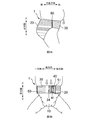
- FIG. 9A is a view of a diaper in a worn state as viewed from the side
- FIG. 9B is a view of the diaper in a worn state as viewed from the front
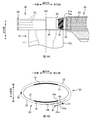
- FIG. 10A is a schematic plan view showing an example of the position of the locking portion when worn
- FIG. 10B is a schematic view when the diaper in the state of FIG. 10A is viewed from above.
- An absorbent article comprising a waistline portion, and a crotch portion provided between the front waistline portion and the rear waistline portion, and an end portion on one side of the rear waistline portion in the lateral direction;
- the one end portion of the front waistline portion in the lateral direction is joined by a first joint portion, and the other end portion of the rear waistline portion in the lateral direction is connected to the front waistline portion when worn.
- Absorption characterized in that it is joined by a latching member having a latchable latching part and a second joint part, and the joint strength of the second joint part is greater than the joint strength of the first joint part. Sex goods. According to such an absorbent article, even if the locking member is pulled when the diaper is worn, the second joint portion (open side) is not easily damaged, and when the diaper is replaced, the first joint portion (open side and The opposite side) can be easily peeled off, and the diaper 1 can be easily replaced.
- each of the first joint and the second joint has a plurality of welding regions, and a plurality of the second joints out of the total area of the second joints.
- the ratio of the area which the said welding area occupies is larger than the ratio of the area which the said several welding area of the said 1st junction part occupies among the area of the whole area
- the absorbent article characterized by the above-mentioned.
- the joint strength of the second joint portion can be made larger than the joint strength of the first joint portion.
- Such an absorbent article wherein a pattern of the plurality of welded areas in the first joint portion is different from a pattern of the plurality of welded areas in the second joint portion.
- the ratio of the area occupied by the welding region in the area of the entire region of the second joint portion is set to a plurality of the first joint portion in the area of the entire region of the first joint portion. It can be made larger than the ratio of the area occupied by the welding region.
- the weld region of the second joint portion has an inner end in the horizontal direction having a predetermined length along the vertical direction. According to such an absorbent article, even when the locking member is pulled in the lateral direction when the absorbent article is worn, and a force acts on the laterally inner end of the welding region of the second joint portion, the end Is unlikely to be the starting point for tears. Therefore, it is possible to make the second joint portion more difficult to break.
- the weld region of the first joint portion has the shortest length in the lateral direction in at least one of the upper end portion and the lower end portion in the longitudinal direction. Goods. According to such an absorbent article, the strength of the upper end and the lower end of the welded region of the first joint is the weakest. Therefore, when a force in the vertical direction is applied to break the first joint portion during replacement of the absorbent article, the upper end portion and the lower end portion of the welding region become the starting point of peeling. Therefore, the first joint portion can be more easily peeled off.
- the end of the locking portion on the side of the second joint portion is located at the end of the crotch portion on the side opposite to the first joint portion. Furthermore, in the state which latched the said latching
- the absorbent article characterized by the above-mentioned. According to such an absorbent article, since the rear waistline portion and the locking member are joined and the second rigid joint portion is located in front of the wearer (abdomen), the wearer's stomach protrudes. A downward displacement of the absorbent article (front waistline portion) can be suppressed.
- Such an absorbent article is characterized in that the rigidity at the second joint portion is greater than the rigidity at the front waistline portion. According to such an absorbent article, the support for the downward displacement of the front waistline portion is more reliable, and the downward displacement of the absorbent article (front waistline portion) due to the protrusion of the wearer's stomach is further suppressed. Is done.
- the number of members overlapping in the second joint portion is greater than the number of members overlapping in the front waistline portion.
- the rigidity in the second joint portion can be made larger than the rigidity in the front waistline portion.
- FIG. 1 is a perspective image view of a single-open pants-type disposable diaper 1 (hereinafter referred to as a diaper).
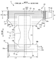
- FIG. 2 is a plan view of the diaper 1 in the unfolded state. In addition, it is a figure of the state which extended the elastic member which the diaper 1 has to such an extent that the wrinkles of the diaper 1 disappear.
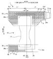
- FIG. 3 is a diagram illustrating the elastic regions X and Y.
- FIG. 4A is a schematic cross-sectional view of the front waistline portion 30,
- FIG. 4B is a schematic cross-sectional view of the back waistline portion 20, and
- FIG. 4C is a schematic cross-sectional view of the locking member 40.
- the diaper 1 has a “longitudinal direction”, a “lateral direction” that intersects the longitudinal direction, and a “front-rear direction” that intersects the longitudinal direction and the lateral direction, and is disposed in the crotch of the wearer to absorb excrement.
- the “absorbent body 10 (inseam)”, the “rear waistline portion 20” covering the back side of the wearer, the “front waistline portion 30” covering the abdomen side of the wearer, and the lateral direction of the rear waistline portion 20 It has a “locking member 40” protruding outward in the lateral direction from the other end.
- the center line RC indicates the center of the rear waistline portion 20 in the lateral direction
- the center line BC indicates a position that is substantially the center of the wearer's body with one leg put in
- the center line AC Indicates the lateral center of the absorbent body 10.
- the center line RC is the same position as the center line BC, and the center lines RC and BC are the other side (right side) in the lateral direction from the center line AC.
- the unfolded state in FIG. 2 is that the first joint 50 and the second joint 51 in FIG. 1 are separated and opened, and the locking member 40 is removed from the front waistline 30 to unfold the entire diaper 1 in a plane. It is in the state. 2, the rear waistline portion 20 and the front waistline portion 30 are disposed such that the longitudinal direction thereof is along the lateral direction of the diaper 1 and is spaced apart in the longitudinal direction. Between these, the absorptive main body 10 (crotch part) is provided so that the longitudinal direction may follow the longitudinal direction of the diaper 1.
- back waistline part 20 is being fixed to the skin side surface of the longitudinal direction one end part of the absorptive main body 10
- front waistline part 30 is being fixed to the skin side surface of the longitudinal direction other end part of the absorptive main body 10.
- the diaper 1 in the unfolded state in FIG. 2 is folded in half at the approximate center in the vertical direction, and the rear waistline portion 20 and the front waistline portion 30 are joined at the first joint portion 50 at the end of one side in the horizontal direction of the diaper 1.
- the leg opening HL1 on one side is formed.
- the rear waistline portion 20 and the front waistline portion 30 are not joined at the end portion on the other side in the lateral direction of the diaper 1, but the end portion on the other side in the lateral direction of the rear waistline portion 20 and the locking member 40 are second. Joined at the joint 51.
- the locking member 40 is locked to the front waistline portion 30, the other leg periphery opening HL2 and the waistline opening HB are formed.
- the absorptive main body 10 (crotch part) has a rectangular shape in plan view, and absorbs and holds liquid 11 and a liquid-permeable surface sheet 12 (for example, nonwoven fabric) that covers the absorbent body 11 from the skin side of the wearer.
- the liquid-impermeable back sheet 13 (for example, a polyethylene film, a polypropylene film, etc.) which covers the absorber 11 from the non-skin side.
- the absorbent body 11 is formed by molding liquid absorbent fibers such as pulp fibers into a predetermined shape such as an hourglass shape, and a superabsorbent polymer is mixed therein.
- the absorbent main body 10 may be provided with a three-dimensional gather portion that prevents side leakage and a leg gather portion that improves the fit around the legs.
- the back waistline part 20 is a planar view shape combining a rectangle and a substantially trapezoid, and is a skin side sheet 21 (for example, a soft sheet such as a nonwoven fabric) located on the skin side of the wearer and a non-skin side located on the non-skin side.
- a sheet 22 (for example, a soft sheet such as a nonwoven fabric) and a plurality of thread rubbers 23 positioned between the skin side sheet 21 and the non-skin side sheet 22 are provided.
- the vertical upper end of the non-skin side sheet 22 is folded back toward the skin so as to cover the upper end of the skin side sheet 21 and the upper end of the absorbent main body 10. This reduces stress on the waistline when worn.
- the lower end portion on one side in the horizontal direction of the rear waistline portion 20 has an inclined portion 20bl that is inclined downward in the vertical direction from the end 20e on one side in the horizontal direction toward the other side.
- the lower end portion on the other side in the lateral direction of the rear waistline portion 20 includes a straight portion 20bs formed substantially parallel to the lower end 30b of the front waistline portion 30, and an inclined portion 20br symmetrical to the inclined portion 20bl with respect to the center line AC. Have.
- the horizontal length L6 of the straight portion 20bs and the inclined portion 20br may be longer than the horizontal length L5 of the inclined portion 20bl (L6> L5).
- the leg opening HL1 on one side is set to a length corresponding to the assumed leg circumference of the wearer and fitted to the wearer's leg, depending on the latching position of the latch member 40.
- the adjustable range of the sizes of the leg opening HL2 and the waist opening HB on the other side can be widened.
- the thread rubber 23 is an elastic member that imparts lateral stretchability to the rear waistline portion 20.
- the plurality of rubber bands 23 are arranged at intervals in the vertical direction, and are arranged along the horizontal direction from the horizontal end 20e on one side of the rear waistline portion 20 to the horizontal end 20e on the other side.
- the rubber thread 23 that overlaps the absorbent body 11 in the vertical direction has a discontinuous portion on the absorbent body 11. Then, the elastic force of the rubber thread 23 does not substantially appear in the first joint portion 50 and the second joint portion 51. Therefore, a region indicated by hatching in FIG. 3 is an elastic region X where the elastic force of the rubber thread 23 is expressed.
- An end Xe1 on one side in the horizontal direction of the elastic region X coincides with an end on the other side (inner side) in the horizontal direction of the first joint portion 50, and an end Xe2 on the other side of the elastic region X is in the lateral direction of the second joint portion 51. Matches one side (inner side) end.
- the distance L1 from the end Xe1 on one side in the horizontal direction of the elastic region X to the center line AC is smaller than the distance L2 from the end Xe2 on the other side in the horizontal direction of the elastic region X to the center line AC (L1). ⁇ L2).
- the center line AC of the absorbent main body 10 is located on one side in the lateral direction with respect to the substantially center line BC of the wearer's body in the state where the wearer's one leg is put in, the locking member When 40 is pulled to the other side in the lateral direction and locked to the front waistline portion 30, the absorbent main body 10 moves to the other lateral side, and the center (AC) of the absorbent main body 10 is the body of the wearer. It approaches the center (BC). Therefore, it is possible to prevent the excrement from leaking and to reduce the uncomfortable feeling when worn. Further, by making the distance L2 longer than the distance L1, the adjustable range of the sizes of the other leg-hole opening HL2 and the trunk-hole opening HB can be widened.
- the distance d from the center line RC of the rear waistline portion 20 to the center line AC of the absorbent main body 10 may be smaller than the difference between the distance L2 and the distance L1 (d ⁇ L2-L1). By doing so, the possibility that the center (AC) of the absorbent main body 10 and the approximate center (BC) of the wearer's body may be further reduced.
- the length H1 of the lateral end 20e on the other side of the rear waistline portion 20 is set to be half of the longitudinal length H3 of the absorbent main body 10 from the lower end 20b of the rear waistline portion 20 to the lower end 30b of the front waistline portion 30. May be reduced (H1 ⁇ H3 / 2).
- the leg opening HL can be made to have a length corresponding to the size of the leg.
- the force of pulling the locking member 40 at the time of locking is easily transmitted to the rear waistline portion 20, which makes it easy to attach.
- the front waistline portion 30 has a rectangular shape in plan view, a skin side sheet 31 (for example, a soft sheet such as a nonwoven fabric) positioned on the skin side of the wearer, and a non-skin side sheet 32 (for example, a nonwoven fabric or the like) positioned on the non-skin side.
- a soft sheet a plurality of thread rubbers 33 positioned between the skin side sheet 31 and the non-skin side sheet 32, and a target region 34 on the non-skin side surface.
- the upper end portion in the vertical direction of the non-skin side sheet 32 is folded back toward the skin side so as to cover the upper end portion of the skin side sheet 31 and the upper end portion of the absorbent main body 10.
- the target region 34 is formed of a member that can be engaged with the locking member 40 (locking portion 41), and is provided in a region on the other side of the center line AC of the absorbent main body 10.
- the lateral length of the front waistline portion 30 is shorter than the lateral length of the rear waistline portion 20.
- the thread rubber 33 is an elastic member that imparts lateral stretchability to the front waistline portion 30, and a plurality of thread rubbers 33 are arranged at intervals in the vertical direction. Further, a rubber thread 33 is provided between the lateral end 30e on one side in the lateral direction of the front waistline portion 30 and the center line AC, and between the lateral end 30e on the other side in the lateral direction and the center line AC. The rubber thread 33 is not provided. The rubber thread 33 is not provided in the region overlapping with the absorbent body 11. As shown in FIG. 3, the region where the rubber thread 33 is arranged between the end of the first joining region 50 on the other side (inner side) in the lateral direction and the center line AC is the elastic region Y. As described above, the thread rubber 33 is not disposed at a portion on the other side in the lateral direction from the center line AC where the locking member 40 is locked, and therefore the locking is easily released due to the expansion and contraction of the thread rubber 33. Can be prevented.
- the distance L3 from the lateral end 30e on one side in the lateral direction of the front waistline 30 to the center line AC is longer than the distance L4 from the centerline AC to the lateral end 30e on the other side in the lateral direction of the front waistline 30. Good (L3> L4).
- the locking member 40 has a substantially trapezoidal shape in plan view, a skin side sheet 42 (for example, non-woven fabric) positioned on the wearer's skin side, a non-skin side sheet 43 (for example, non-woven fabric) positioned on the non-skin side, and a target It has the latching
- FIG. 4C the upper end portion in the vertical direction of the non-skin side sheet 43 is folded toward the skin side so as to cover the upper end portion of the skin side sheet 42.
- the locking portion 41 include a surface fastener including a plurality of locking protrusions (hooks), and examples of the target region 34 include a surface fastener or a nonwoven fabric including a loop that engages with the hook.
- the end on one side of the rear waistline portion 20 in the lateral direction and the end on one side of the front waistline portion 30 in the lateral direction are joined by the first joint 50, and in the lateral direction.
- the other end portion of the rear waistline portion 20 is joined by a locking member 40 having a locking portion 41 that can be locked to the front waistline portion 30 when worn, and a second joint portion 51.
- the bonding method in the first bonding part 50 and the second bonding part 51 is welding (specifically, thermal welding or ultrasonic welding), and the first bonding part 50 and the second bonding part 51 each include a plurality of bonding methods. It has a welding area (concave part).
- the joining method of the 1st junction part 50 and the 2nd junction part 51 is not restricted to joining by welding, For example, joining by an adhesive agent etc. may be sufficient.
- the locking member 40 is removed from the front waistline portion 30 at the end portion on the other side in the lateral direction, and the first end portion on the one side in the lateral direction is removed.
- the joint 50 is peeled off. That is, the second joint portion 51 is not peeled off. Nevertheless, it is assumed that the bonding strength of the second bonding portion 51 is set so as to be easily peeled off at the time of replacement in accordance with the first bonding portion 50. Then, when the locking member 40 is pulled in the lateral direction and the waistline direction of the diaper 1 when the diaper 1 is attached, the second joint portion 51 may be damaged. Conversely, if the bonding strength of the first bonding portion 50 is increased so that the second bonding portion 51 is not damaged, the first bonding portion 50 is difficult to peel off during replacement.
- the bonding strength of the second bonding portion 51 is made larger than the bonding strength of the first bonding portion 50. By doing so, even if the locking member 40 is pulled when the diaper 1 is attached, the second joint portion 51 is not easily damaged. When the diaper 1 is replaced, the first joint portion 50 is easily peeled off, and the diaper 1 is replaced. It becomes easy.
- the joint strengths of the first joint portion 50 and the second joint portion 51 may be individually set in accordance with each application.
- samples 1 and 2 are cut out from the diaper 1 to be measured.
- the sample 1 includes the entire area of the first joint portion 50 and includes a part of the rear waistline portion 20 located on one side of the first joint portion 50 in the lateral direction (the waistline direction) of the diaper 1 and the front side located on the other side.
- the sample 2 includes the entire region of the second joint portion 51 and includes a part of the rear waistline portion 20 located on one side of the second joint portion 51 in the lateral direction (the waistline direction) of the diaper 1 and a relationship located on the other side.
- Part of the stop member 40 Part of the stop member 40.
- sample 1 or sample 2 is set on the upper and lower chucks of a tensile tester (for example, Instron series 5564 manufactured by Instron Corporation).
- a tensile tester for example, Instron series 5564 manufactured by Instron Corporation.
- the rear waistline portion 20 is fixed to one of the upper and lower chucks, and the front waistline portion 30 is fixed to the other so that the first joint portion 50 is located at the center between the chucks.
- the rear waistline portion 20 is fixed to one of the upper and lower chucks, and the locking member 40 is fixed to the other so that the second joint portion 51 is located at the center between the chucks.
- the upper and lower chucks are separated at a predetermined pulling speed (for example, 500 mm / min), and the samples 1 and 2 are pulled.
- the load (N) at that time is acquired.
- n for example, 10
- measurement results are obtained, and an average value of n loads (N) is calculated.
- the average value (N) of sample 1 is set as the bonding strength of the first bonding portion 50
- the average value (N) of sample 2 is set as the bonding strength of the second bonding portion 51, and both values are compared.
- the bonding strength of the entire first bonding portion 50 is not limited to the comparison of the bonding strength of the entire second bonding portion 51.
- the bonding strength of the first bonding portion 50 and the bonding strength of the second bonding portion 51 per unit width in the longitudinal direction of the diaper 1 may be compared.
- the bonding strength (N) obtained by the above measurement method may be converted into a value (for example, N / 25 mm) per unit width (for example, 25 mm) in the vertical direction.
- samples 1 and 2 having a length of 25 mm in the longitudinal direction are cut out from the diaper 1, and each joint strength of sample 1 including a part of the first joint part 50 and sample 2 including a part of the second joint part 51 is obtained.
- the distance between the chucks is continuously separated, and the load when the first joint 50 of the sample 1 and the second joint 51 of the sample 2 are broken is used to join the first joint 50 and the second joint 51. It is good also as intensity.
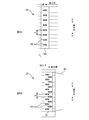
- FIG. 5A shows the first joint 50 in the first embodiment
- FIG. 5B shows the second joint 51 in the first embodiment.
- the number of welding regions 52 and 53 included in the first joint portion 50 and the second joint portion 51 is drawn smaller than the actual number.
- the first joint portion 50 has eight substantially rectangular welding regions 52, specifically, eight so-called saddle-shaped welding regions 52 whose rectangular short sides are curved.
- the eight welding regions 52 are arranged in a line at a predetermined interval d1 in the vertical direction.
- the second bonding portion 51 has 16 welding regions 53 having the same shape and the same size as the welding regions 53 included in the first bonding portion 50.
- the 16 welding regions 53 are arranged in two rows in the horizontal direction while being arranged at a predetermined interval d2 in the vertical direction.
- the pattern of the plurality of weld regions 52 in the first joint portion 50 is different from the pattern of the plurality of weld regions 53 in the second joint portion 51.
- the number of welded regions 53 included in the second joint portion 51 is larger.
- the vertical interval d2 in which the weld regions 53 of the second joint 51 are arranged is narrower than the vertical interval d1 in which the weld regions 52 of the first joint 50 are arranged.
- the ratio (A2 / A1) of the area (A2) occupied by the plurality of welding regions 53 of the second joint portion 51 in the area (A1) of the entire region of the second joint portion 51 is the first joint portion 50. Is larger than the ratio (A4 / A3) of the area (A4) occupied by the plurality of welding regions 52 of the first joint portion 50 in the total area (A3). Therefore, the bonding strength of the second bonding portion 51 is greater than the bonding strength of the first bonding portion 50, the second bonding portion 51 is not easily damaged during mounting, and the first bonding portion 50 is easily peeled off during replacement. .
- Example 2 shows the first joint 50 in the second embodiment
- FIG. 6B shows the second joint 51 in the second embodiment
- the number of the welding regions 52 and 53 is the same (eight) in the first joint portion 50 and the second joint portion 51
- the vertical interval d1 in which the weld regions 52 and 53 are arranged is the same.
- the weld region 52 of the first joint 50 and the weld region 53 of the second joint 51 have the same shape (saddle shape), but compared to the weld region 52 of the first joint 50, the second joint 51.
- the welding region 53 is larger.
- Example 2 the pattern of the plurality of welding regions 52 in the first joint portion 50 is different from the pattern of the plurality of welding regions 53 in the second joint portion 51, and the welding region 52 of the first joint portion 50 is different.
- the welding region 53 of the second joint portion 51 is larger. Therefore, the ratio (A2 / A1) of the area (A2) occupied by the plurality of welding regions 53 of the second joint portion 51 in the area (A1) of the entire region of the second joint portion 51 is the first joint portion 50. Is larger than the ratio (A4 / A3) of the area (A4) occupied by the plurality of welding regions 52 of the first joint portion 50 in the total area (A3).
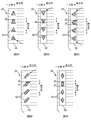
- FIGS. 7A to 7C are diagrams illustrating the second joint portion 51 in the third embodiment.
- the welding region 53 of the second joint portion 51 shown in FIG. 7A has the same substantially rectangular shape (saddle shape) as the welding region 53 of the first embodiment. However, the directions are different, and in the welding region 53 of Example 3, the long side is along the vertical direction.
- the welding region 53 shown in FIG. 7B has a square shape, and the sides are along the vertical direction.
- the welding region 53 shown in FIG. 7C has a triangular shape, and one side of the three sides extends along the vertical direction and is located on the inner side (one side) in the horizontal direction.
- the end 53e on the laterally inner side (one side) of the welding region 53 of the second joint 51 is formed. Force acts. Therefore, if the end 53e is, for example, a vertex of a triangle or a point on an arc, the end 53e becomes a starting point of breakage. Therefore, as in the welding region 53 shown in FIGS. 7A to 7C, the inner end 53 e in the horizontal direction of the welding region 53 may have a predetermined length along the vertical direction. By doing so, the end 53e is less likely to be a starting point of breakage, and the second joint 51 is less likely to be damaged.
- the inner end 53e in the horizontal direction of the welding region 53 is along the vertical direction is not limited to the case where the end 53e and the vertical direction are parallel to each other, and includes the case where the end 53e intersects the vertical direction. . Even in the case of crossing, compared to the case where the end 53e is a point, the end 53e is less likely to be a starting point of breakage, and the second joint portion 51 is less likely to be damaged.
- the shape of the welding region 53 in the third embodiment is not limited to that shown in FIG. 7, and may be, for example, a polygon such as a pentagon, a semicircle, or the like. To be located.
- the ratio of the area occupied by the welded regions 52 and 53 is larger than that of the first joint portion 50 so that the joint strength of the second joint portion 51 is larger than the joint strength of the first joint portion 50. Therefore, it is preferable to make the second joint portion 51 larger. Therefore, as in the first and second embodiments, the number of the welding regions 52 may be reduced or the size of the first bonding portion 50 may be reduced as compared with the second bonding portion 52. Moreover, the shape of the welding area
- Example 4 8A to 8E are diagrams illustrating the first joint portion 50 according to the fourth embodiment.
- the weld region 52 of the first joint 50 shown in FIGS. 8A to 8C has a triangular shape.
- one vertex is positioned on the upper side in the vertical direction
- the welding region 52 of FIG. 8B one vertex is positioned on the lower side in the vertical direction
- the welding region 52 of FIG. It is located in a direction inclined inward (on the other side) in the horizontal direction toward the upper side in the vertical direction.
- the welding region 52 shown in FIG. 8E has a rhombus shape, with one vertex located on the upper side in the vertical direction and one vertex located on the lower side.
- the horizontal length d3 is the shortest at the upper end in the vertical direction
- the horizontal length d3 is the shortest at the lower end in the vertical direction in the welded region 52 of FIG. 8B.
- the horizontal length d3 is the shortest at the upper end and the lower end in the vertical direction. That is, in the welding region 52 of the first joint portion 50 according to the fourth embodiment, the horizontal length d3 of at least one of the upper end portion and the lower end portion in the vertical direction is the shortest. Therefore, in the welding region 52 of the first joint portion 50, the joint strength is the weakest at the upper end portion and the lower end portion in the vertical direction.
- the first joint portion 50 When the diaper is replaced, the first joint portion 50 is peeled off along the vertical direction, and a vertical force acts on the first joint portion 50. Therefore, the upper end part and lower end part of the welding area 52 become the starting point of peeling by weakening the joining strength of the upper end part and the lower end part of the welding area 52 of the first joint part 50. Therefore, the first joint 50 can be easily peeled off, and the diaper 1 can be easily replaced.
- the exchanger of the diaper 1 puts a finger inside the rear waistline portion 20 and the front waistline portion 30 to peel it off. Therefore, at the start of peeling, a force in a direction inclined with respect to the vertical direction from the inner side in the horizontal direction to the outer side acts on the first joint portion 50. For this reason, for example, as in the welding region 52 of FIG. 8C, one of the vertices of the triangle is positioned in a direction inclined outward in the horizontal direction toward the lower side in the vertical direction, and another apex is directed toward the upper side in the vertical direction. And in a direction inclined laterally outward.
- the apex of the welding region 52 becomes the starting point of the peeling, and the first joint portion 50 is more easily peeled off.
- region 52 of FIG. 8A since one of the vertices of a triangle is located in the direction which inclined to the outer side of the horizontal direction toward the upper side of the vertical direction, it is easy to peel off from the lower side of the vertical direction.
- 8B and 8D since the apex of the triangle and the apex of the curved short side are located in a direction inclined outward in the horizontal direction toward the lower side in the vertical direction, the upper side in the vertical direction It is easy to peel off from.
- the ratio of the area occupied by the welded regions 52 and 53 is larger than that of the first joint portion 50 so that the joint strength of the second joint portion 51 is larger than the joint strength of the first joint portion 50. Therefore, it is preferable to make the second joint portion 51 larger. Therefore, as in the first and second embodiments, the number of the welding regions 52 may be reduced or the size of the first bonding portion 50 may be reduced as compared with the second bonding portion 52. Moreover, since it is not necessary to peel off the 2nd junction part 51, it is preferable that the shape of the welding area
- region 53 of the 2nd junction part 51 is a shape shown in Example 3 instead of the shape shown in FIG.
- the number of the welding regions 52 is not limited to the uniform arrangement along the vertical direction, and the number of the welding regions 52 is reduced at the upper end portion and the lower end portion of the first bonding portion 50 as compared with the central portion. Or may be reduced in size. By doing so, since the bonding strength is weak at the upper end portion and the lower end portion of the first bonding portion 50, the first bonding portion 50 is more easily peeled off.
- the method of increasing the bonding strength of the second bonding portion 51 than the bonding strength of the first bonding portion 50 is not limited to the method of increasing the proportion of the area occupied by the welding region 53.
- the bonding strength of each welding region 53 of the second bonding portion 51 may be greater than the bonding strength of each welding region 52 of the first bonding portion 50.
- the number of sheets stacked and the basis weight of fibers are increased in the second bonding portion 51 than in the first bonding portion 50, and the pressure applied during welding is increased or the welding time is increased. Or make it longer.
- the vertical length H ⁇ b> 2 of the second joint portion 51 is shorter than the vertical length H ⁇ b> 4 of the first joint portion 50.
- the length H2 may be equal to the length H4, or the length H2 may be longer than the length H4.
- the length H2 in the vertical direction of the second joint portion 51 may be longer than half the length H1 of the end 20e on the other side in the horizontal direction of the rear waistline portion 20 (H2> H1 / 2).
- FIG. 10A is a schematic plan view showing an example of the position of the locking portion 41 when worn
- FIG. 10B is a schematic view when the diaper 1 in the state of FIG. 10A is viewed from above.
- a so-called pants-type diaper that is, a diaper in which a rear waistline portion and a front waistline portion are joined to each other at both lateral ends, the joint portions are located on both sides of the wearer. And the soft site
- the soft part of the front waistline part receives a downward force from the stomach of the wearer, and the diaper tends to shift downward.
- the first joint portion 50 which is a joint portion between the rear waistline portion 20 and the front waistline portion 30, is one side of the wearer.
- the 2nd junction part 51 which is a junction part of the back waistline part 20 and the latching member 40 is located in a wearer's front (abdomen).
- the end 41 e end on the other side in the lateral direction
- the locking portion 41 on the second joint portion 51 side is the absorbent main body 10 (the crotch portion).
- the second bonding portion 51 is It is located on the front side of the position of one joint 50.
- the rigidity of the second joint portion 51 is relatively high.
- the 2nd junction part 51 with the high rigidity is located in a wearer's front (abdomen)
- the protrusion of a wearer's stomach can be supported by the 2nd junction part 51.
- FIG. Therefore, the position shift to the downward direction of the diaper 1 (front waistline part 30) by the protrusion of a wearer's stomach can be suppressed, and the wearing property of the diaper 1 becomes favorable.
- the bonding strength of the second bonding portion 51 is larger than the bonding strength of the first bonding portion 50, and the rigidity of the second bonding portion 51 is higher. Therefore, the protrusion of the wearer's stomach can be firmly supported by the second joint portion 51, and the downward displacement of the diaper 1 due to the protrusion of the wearer's stomach can be more reliably suppressed.
- the end 34 e on the other side in the horizontal direction of the target region 34 and the end 10 e on the other side in the horizontal direction of the absorbent main body 10 coincide with each other.
- the wearer of the diaper 1 makes the locking portion 41 fit in the target region 34 so that the locking member 40 is firmly locked to the front waistline portion 30. That is, it is highly probable that the end 41e on the other side in the lateral direction of the locking portion 41 is located on the inner side (one side) in the lateral direction than the end 10e on the other side in the lateral direction of the absorbent main body 10. Therefore, as shown in FIG.
- the second joint portion 51 can be positioned in front of the position of the first joint portion 50. it can.
- the rigidity at the second joint portion 51 is larger than the rigidity at the front waistline portion 30. This is because the second bonding portion 51 has a highly rigid welding region 53, whereas the front waistline portion 30 is formed of a skin side sheet 31 such as a soft nonwoven fabric and a non-skin side sheet 32. is there. Even if the second joint portion 51 and the front waistline portion 30 have the same rigidity, in the diaper 1, the second joint portion 51 and the front waistline portion 30 are in the front-rear direction (thickness direction) in front of the wearer. Is superimposed on. Therefore, compared with the underpants type diaper which does not have the 2nd junction part 51 ahead of a wearer, position shift to the lower part of diaper 1 can be controlled.
- the support with respect to the position shift of the front waistline part 30 becomes more reliable, and the diaper 1 by the protrusion of a wearer's stomach is improved.
- the downward displacement is further suppressed.
- segmented the value measured by the Gurley bending resistance by the length of the sample piece can be illustrated, for example.
- the Gurley bending resistance can be measured according to JIS-L1096 using a No. 311 Gurley type flexibility tester manufactured by Yasuda Seiki Seisakusho.
- the two sheets of the skin side sheet 31 and the non-skin side sheet 32 overlap, whereas in the second joint portion 51, FIG. 4B and FIG.
- seat 43 of the latching member 40 have overlapped a total of four sheets. That is, the number of members overlapping in the second joint portion 51 is greater than the number of members overlapping in the front waistline portion 30.
- the rigidity in the 2nd junction part 51 is larger, and the position shift to the downward direction of the diaper 1 by the protrusion of a wearer's stomach can be suppressed more reliably.
- the rigidity of the second joint portion 51 can be made larger than the rigidity of the front waistline portion 30.
- the longitudinal length H2 of the second joint portion 51 is shorter than the longitudinal length H1 of the end portion on the other lateral side of the rear waistline portion 20.
- it may be equal to the length H1. That is, you may provide the 2nd junction part 51 ranging from the upper end of the edge part of the horizontal direction other side of the back waistline part 20 to a lower end.
- the elastic member included in the diaper 1 is not limited to a thread-like elastic member such as rubber thread, but may be a sheet-like elastic member, for example.
- segmented into three parts was illustrated, it is not restricted to this, The diaper in which the back waistline part 20 and the front waistline part 30 were formed integrally, the back waistline part 20, the front waistline part 30 and a diaper in which the absorbent main body 10 is integrally formed.
- the wear object of the diaper 1 is made into the infant in the said embodiment, adults, such as elderly people, are good also as a wear object.
- the absorbent article is not limited to being used as a diaper, but may be used as a sanitary product, for example.
- the lengths H1 to H4, L1 to L6, d, and d1 to d3 shown in FIGS. 2, 3, 5, 6, and 8 are compared with each other. This is a comparison in a state where the portion 20 and the front waistline portion 30 are extended.
- the “extended state” refers to a state in which the absorbent main body 10 is extended in the vertical direction, and the rear waistline portion 20 and the front waistline portion 30 are extended in the horizontal direction.
- a state in which the longitudinal dimension of the absorbent main body 10 is elongated in the longitudinal direction until the longitudinal dimension is the same as or close to the longitudinal dimension of the topsheet 12, and the lateral direction of the rear waistline portion 20 A state in which the size of the skin side sheet 21 and the non-skin side sheet 22 are the same as, or close to, the length in the lateral direction, and the front waistline portion. 30 is a state in which the lateral dimension is extended in the lateral direction until the lateral dimension of the skin-side sheet 31 and the lateral dimension of the non-skin-side sheet 32 are the same or close to these dimensions. .
- SYMBOLS 1 Diaper (absorbent article), 10 absorptive main body (crotch lower part), 11 absorber, 12 surface sheet, 13 back sheet, 20 back waistline part, 21 skin side sheet, 22 non-skin side sheet, 23 thread rubber, 30 Front waistline part, 31 skin side sheet, 32 non-skin side sheet, 33 thread rubber, 34 target area, 40 locking member, 41 locking part, 42 skin side sheet, 43 non skin side sheet, 50 first joint part, 51 2nd joint part, 52 welding area
Landscapes
- Health & Medical Sciences (AREA)
- Epidemiology (AREA)
- Engineering & Computer Science (AREA)
- Biomedical Technology (AREA)
- Heart & Thoracic Surgery (AREA)
- Vascular Medicine (AREA)
- Life Sciences & Earth Sciences (AREA)
- Animal Behavior & Ethology (AREA)
- General Health & Medical Sciences (AREA)
- Public Health (AREA)
- Veterinary Medicine (AREA)
- Absorbent Articles And Supports Therefor (AREA)
Abstract
縦方向と横方向と前後方向とを有し、前記横方向に沿った前胴回り部(30)と、前記横方向に沿った後胴回り部(20)と、前記前胴回り部(30)と前記後胴回り部(20)との間に設けられた股下部(10)と、を備えた吸収性物品(1)であって、前記横方向における前記後胴回り部(20)の一方側の端部と、前記横方向における前記前胴回り部(30)の一方側の端部とは、第1接合部(50)によって接合されており、前記横方向における前記後胴回り部(20)の他方側の端部は、着用時に前記前胴回り部(30)に係止可能な係止部(41)を有する係止部材(40)と第2接合部(51)によって接合されており、前記第2接合部(51)の接合強度は、前記第1接合部(50)の接合強度よりも大きいことを特徴とする吸収性物品。
Description
本発明は、吸収性物品に関する。
従来、排泄物を吸収する吸収性物品として所謂テープ型やパンツ型の使い捨ておむつが知られている。また、特許文献1には、前後のウエスト部それぞれの一方(例えば左)の側部を互いに接合してレッグホールを形成し、他方(例えば右)の側部を未接合とし、後側の未接合ウエスト部にレッグホールを形成し得る係止部材(接合手段)を設けた使い捨ておむつが記載されている。
特許文献1に記載されているような所謂片開きパンツ型のおむつにおいて、交換時に、前後のウェスト部の接合部が引き剥がし易くなるように、当該接合部の接合強度が設定され、後側のウエスト部と係止部材との接合部も同程度の接合強度に設定されたとする。そうすると、おむつの装着時に係止部材が引っ張られた際に、後側のウエスト部と係止部材との接合部が破損してしまうおそれがある。
本発明は、上記のような問題に鑑みてなされたものであって、片開きパンツ型のおむつにおいて、装着時にオープン側が破損し難く、且つ、交換時にオープン側と反対側が引き剥がし易い吸収性物品を提供することを目的とする。
上記目的を達成するための主たる発明は、縦方向と、前記縦方向と交差する横方向と、前記縦方向及び前記横方向と交差する前後方向と、を有し、前記横方向に沿った前胴回り部と、前記横方向に沿った後胴回り部と、前記前胴回り部と前記後胴回り部との間に設けられた股下部と、を備えた吸収性物品であって、前記横方向における前記後胴回り部の一方側の端部と、前記横方向における前記前胴回り部の一方側の端部とは、第1接合部によって接合されており、前記横方向における前記後胴回り部の他方側の端部は、着用時に前記前胴回り部に係止可能な係止部を有する係止部材と第2接合部によって接合されており、前記第2接合部の接合強度は、前記第1接合部の接合強度よりも大きいことを特徴とする吸収性物品である。
本発明の他の特徴については、本明細書及び添付図面の記載により明らかにする。
本発明の他の特徴については、本明細書及び添付図面の記載により明らかにする。
本発明によれば、片開きパンツ型のおむつにおいて、装着時にオープン側が破損し難く、且つ、交換時にオープン側と反対側が引き剥がし易い吸収性物品を提供することができる。
本明細書及び添付図面の記載により、少なくとも以下の事項が明らかとなる。
縦方向と、前記縦方向と交差する横方向と、前記縦方向及び前記横方向と交差する前後方向と、を有し、前記横方向に沿った前胴回り部と、前記横方向に沿った後胴回り部と、前記前胴回り部と前記後胴回り部との間に設けられた股下部と、を備えた吸収性物品であって、前記横方向における前記後胴回り部の一方側の端部と、前記横方向における前記前胴回り部の一方側の端部とは、第1接合部によって接合されており、前記横方向における前記後胴回り部の他方側の端部は、着用時に前記前胴回り部に係止可能な係止部を有する係止部材と第2接合部によって接合されており、前記第2接合部の接合強度は、前記第1接合部の接合強度よりも大きいことを特徴とする吸収性物品。
このような吸収性物品によれば、おむつの装着時に係止部材が引っ張られても第2接合部(オープン側)が破損し難く、また、おむつの交換時には、第1接合部(オープン側と反対側)が引き剥がし易くなり、おむつ1を交換し易くなる。
縦方向と、前記縦方向と交差する横方向と、前記縦方向及び前記横方向と交差する前後方向と、を有し、前記横方向に沿った前胴回り部と、前記横方向に沿った後胴回り部と、前記前胴回り部と前記後胴回り部との間に設けられた股下部と、を備えた吸収性物品であって、前記横方向における前記後胴回り部の一方側の端部と、前記横方向における前記前胴回り部の一方側の端部とは、第1接合部によって接合されており、前記横方向における前記後胴回り部の他方側の端部は、着用時に前記前胴回り部に係止可能な係止部を有する係止部材と第2接合部によって接合されており、前記第2接合部の接合強度は、前記第1接合部の接合強度よりも大きいことを特徴とする吸収性物品。
このような吸収性物品によれば、おむつの装着時に係止部材が引っ張られても第2接合部(オープン側)が破損し難く、また、おむつの交換時には、第1接合部(オープン側と反対側)が引き剥がし易くなり、おむつ1を交換し易くなる。
かかる吸収性物品であって、前記第1接合部及び前記第2接合部はそれぞれ、溶着領域を複数有し、前記第2接合部の全体の領域の面積のうち前記第2接合部の複数の前記溶着領域が占める面積の割合は、前記第1接合部の全体の領域の面積のうち前記第1接合部の複数の前記溶着領域が占める面積の割合よりも大きいことを特徴とする吸収性物品。
このような吸収性物品によれば、第2接合部の接合強度を、第1接合部の接合強度よりも大きくすることができる。
このような吸収性物品によれば、第2接合部の接合強度を、第1接合部の接合強度よりも大きくすることができる。
かかる吸収性物品であって、前記第1接合部における複数の前記溶着領域のパターンは、前記第2接合部における複数の前記溶着領域のパターンと異なっていることを特徴とする吸収性物品。
このような吸収性物品によれば、第2接合部の全体の領域の面積のうち溶着領域が占める面積の割合を、第1接合部の全体の領域の面積のうち第1接合部の複数の溶着領域が占める面積の割合よりも大きくすることができる。また、第2接合部をより破損し難くしたり、第1接合部をより引き剥がし易くしたりすることができる。
このような吸収性物品によれば、第2接合部の全体の領域の面積のうち溶着領域が占める面積の割合を、第1接合部の全体の領域の面積のうち第1接合部の複数の溶着領域が占める面積の割合よりも大きくすることができる。また、第2接合部をより破損し難くしたり、第1接合部をより引き剥がし易くしたりすることができる。
かかる吸収性物品であって、前記第2接合部の前記溶着領域は、前記横方向の内側の端が、前記縦方向に沿って所定の長さを有することを特徴とする吸収性物品。
このような吸収性物品によれば、吸収性物品の着用時に係止部材が横方向に引っ張られ、第2接合部の溶着領域の横方向の内側の端に力が作用しても、当該端が破れの起点となり難い。よって、第2接合部をより破損し難くすることができる。
このような吸収性物品によれば、吸収性物品の着用時に係止部材が横方向に引っ張られ、第2接合部の溶着領域の横方向の内側の端に力が作用しても、当該端が破れの起点となり難い。よって、第2接合部をより破損し難くすることができる。
かかる吸収性物品であって、前記第1接合部の前記溶着領域は、前記縦方向の上端部と下端部のうちの少なくとも一方における前記横方向の長さが最も短いことを特徴とする吸収性物品。
このような吸収性物品によれば、第1接合部の溶着領域のうち上端部や下端部の強度が最も弱くなる。そのため、吸収性物品の交換時に第1接合部を破るために縦方向の力が作用した際に、溶着領域の上端部や下端部が引き剥がしの起点となる。よって、第1接合部をより引き剥がし易くすることができる。
このような吸収性物品によれば、第1接合部の溶着領域のうち上端部や下端部の強度が最も弱くなる。そのため、吸収性物品の交換時に第1接合部を破るために縦方向の力が作用した際に、溶着領域の上端部や下端部が引き剥がしの起点となる。よって、第1接合部をより引き剥がし易くすることができる。
かかる吸収性物品であって、前記横方向において、前記係止部の、前記第2接合部の側の端が、前記股下部の、前記第1接合部とは反対側の端に位置するように、前記前胴回り部に前記係止部を係止した状態において、前記第2接合部は、前記第1接合部の位置よりも前側に位置していることを特徴とする吸収性物品。
このような吸収性物品によれば、後胴回り部と係止部材とが接合されて剛性の高い第2接合部が、着用者の前方(腹部)に位置するため、着用者のお腹の出っ張りによる吸収性物品(前胴回り部)の下方への位置ずれを抑制できる。
このような吸収性物品によれば、後胴回り部と係止部材とが接合されて剛性の高い第2接合部が、着用者の前方(腹部)に位置するため、着用者のお腹の出っ張りによる吸収性物品(前胴回り部)の下方への位置ずれを抑制できる。
かかる吸収性物品であって、前記第2接合部における剛性は、前記前胴回り部における剛性よりも大きいことを特徴とする吸収性物品である。
このような吸収性物品によれば、前胴回り部の下方への位置ずれに対する支えがより確実となり、着用者のお腹の出っ張りによる吸収性物品(前胴回り部)の下方への位置ずれがより抑制される。
このような吸収性物品によれば、前胴回り部の下方への位置ずれに対する支えがより確実となり、着用者のお腹の出っ張りによる吸収性物品(前胴回り部)の下方への位置ずれがより抑制される。
かかる吸収性物品であって、前記第2接合部において重なっている部材の点数は、前記前胴回り部において重なっている部材の点数よりも多いことを特徴とする吸収性物品。
このような吸収性物品によれば、第2接合部における剛性を、前胴回り部における剛性よりも大きくすることができる。
このような吸収性物品によれば、第2接合部における剛性を、前胴回り部における剛性よりも大きくすることができる。
以下、本発明に係る吸収性物品として、主に乳幼児を着用対象とした片開きパンツ型使い捨ておむつを例に挙げて実施形態を説明する。
===片開きパンツ型使い捨ておむつ1の基本構成===
図1は、片開きパンツ型使い捨ておむつ1(以下、おむつ)の斜視イメージ図である。図2は、展開状態のおむつ1の平面図である。なお、おむつ1の皺がなくなる程度までおむつ1が有する弾性部材を伸長させた状態の図である。図3は、弾性領域X、Yについて説明する図である。図4Aは、前胴回り部30の断面模式図であり、図4Bは、後胴回り部20の断面模式図であり、図4Cは、係止部材40の断面模式図である。
図1は、片開きパンツ型使い捨ておむつ1(以下、おむつ)の斜視イメージ図である。図2は、展開状態のおむつ1の平面図である。なお、おむつ1の皺がなくなる程度までおむつ1が有する弾性部材を伸長させた状態の図である。図3は、弾性領域X、Yについて説明する図である。図4Aは、前胴回り部30の断面模式図であり、図4Bは、後胴回り部20の断面模式図であり、図4Cは、係止部材40の断面模式図である。
おむつ1は、「縦方向」と、縦方向と交差する「横方向」と、縦方向及び横方向と交差する「前後方向」とを有するとともに、着用者の股下に配置されて排泄物を吸収する「吸収性本体10(股下部)」と、着用者の背側を覆う「後胴回り部20」と、着用者の腹側を覆う「前胴回り部30」と、後胴回り部20の横方向他方側の端部から横方向の外側に突出した「係止部材40」とを有する。図2、図3において、中心線RCは後胴回り部20の横方向の中心を示し、中心線BCは片脚を入れた状態の着用者の身体の略中心となる位置を示し、中心線ACは吸収性本体10の横方向の中心を示す。中心線RCを中心線BCと同位置とし、中心線RC、BCを中心線ACよりも横方向の他方側(右側)とする。
図2の展開状態とは、図1の第1接合部50及び第2接合部51を分離して開くとともに、係止部材40を前胴回り部30から取り外して、おむつ1全体を平面的に展開した状態である。図2の展開状態において、後胴回り部20及び前胴回り部30は、その長手方向がおむつ1の横方向に沿い、且つ、縦方向に間隔を空けて配置されている。これらの間に、吸収性本体10(股下部)が、その長手方向がおむつ1の縦方向に沿うように設けられている。そして、吸収性本体10の長手方向一端部の肌側面に後胴回り部20が固定され、吸収性本体10の長手方向他端部の肌側面に前胴回り部30が固定されている。
図2の展開状態のおむつ1は縦方向の略中央で二つ折りされ、おむつ1の横方向一方側の端部において、後胴回り部20と前胴回り部30とが第1接合部50にて接合されている。その結果、一方側の脚回り開口部HL1が形成されている。
おむつ1の横方向他方側の端部では、後胴回り部20と前胴回り部30とが接合されていないが、後胴回り部20の横方向他方側の端部と係止部材40とが第2接合部51にて接合されている。係止部材40が前胴回り部30に係止されることによって、他方側の脚回り開口部HL2と胴回り開口部HBとが形成される。
おむつ1の横方向他方側の端部では、後胴回り部20と前胴回り部30とが接合されていないが、後胴回り部20の横方向他方側の端部と係止部材40とが第2接合部51にて接合されている。係止部材40が前胴回り部30に係止されることによって、他方側の脚回り開口部HL2と胴回り開口部HBとが形成される。
このような片開きパンツ型のおむつ1の着用方法は、まず、おむつ1の装着者が、一方側の脚回り開口部HL1に着用者の片脚(右脚)を入れる。次に、おむつ1の装着者は、他方側の脚回り開口部HL2に着用者のもう一方の脚(左脚)を配置するとともに、片方の手で前胴回り部30の横方向他方側の端部を押さえ、もう一方の手で係止部材40を引っ張り、係止部材40を前胴回り部30に係止する。そのため、所謂パンツ型のおむつを履かせるときのように、脚回り開口部に両脚を同時に入れる必要がなくなるので、脚をバタつかせている乳幼児であっても、おむつ1を容易に履かせることができる。
(吸収性本体10)
吸収性本体10(股下部)は、平面視長方形であり、液体を吸収して保持する吸収体11と、吸収体11を着用者の肌側から覆う液透過性の表面シート12(例えば不織布)と、吸収体11を非肌側から覆う液不透過性の裏面シート13(例えばポリエチレンフィルムやポリプロピレンフィルム等)を有する。吸収体11は、パルプ繊維等の液体吸収性繊維を例えば砂時計形状等の所定形状に成形されたものであり、その内部には高吸収性ポリマーが混入されている。なお、図示しないが、横漏れを防ぐ立体ギャザー部や脚回りのフィット性を向上させるレッグギャザー部を吸収性本体10に設けてもよい。
吸収性本体10(股下部)は、平面視長方形であり、液体を吸収して保持する吸収体11と、吸収体11を着用者の肌側から覆う液透過性の表面シート12(例えば不織布)と、吸収体11を非肌側から覆う液不透過性の裏面シート13(例えばポリエチレンフィルムやポリプロピレンフィルム等)を有する。吸収体11は、パルプ繊維等の液体吸収性繊維を例えば砂時計形状等の所定形状に成形されたものであり、その内部には高吸収性ポリマーが混入されている。なお、図示しないが、横漏れを防ぐ立体ギャザー部や脚回りのフィット性を向上させるレッグギャザー部を吸収性本体10に設けてもよい。
(後胴回り部20)
後胴回り部20は、長方形と略台形を組み合わせた平面視形状であり、着用者の肌側に位置する肌側シート21(例えば不織布等の柔らかいシート)と、非肌側に位置する非肌側シート22(例えば不織布等の柔らかいシート)と、肌側シート21と非肌側シート22の間に位置する複数の糸ゴム23とを有する。図4Bに示すように、非肌側シート22の縦方向の上端部が、肌側シート21の上端部及び吸収性本体10の上端部を覆うように、肌側に向かって折り返されている。これにより着用時に胴回り部分に掛かるストレスが軽減される。
後胴回り部20は、長方形と略台形を組み合わせた平面視形状であり、着用者の肌側に位置する肌側シート21(例えば不織布等の柔らかいシート)と、非肌側に位置する非肌側シート22(例えば不織布等の柔らかいシート)と、肌側シート21と非肌側シート22の間に位置する複数の糸ゴム23とを有する。図4Bに示すように、非肌側シート22の縦方向の上端部が、肌側シート21の上端部及び吸収性本体10の上端部を覆うように、肌側に向かって折り返されている。これにより着用時に胴回り部分に掛かるストレスが軽減される。
図2に示すように、後胴回り部20の横方向一方側の下端部は、横方向一方側の端20eから他方側に向かって、縦方向の下方に傾斜している傾斜部20blを有する。後胴回り部20の横方向他方側の下端部は、前胴回り部30の下端30bと略平行に形成された直線部20bsと、中心線ACに対して傾斜部20blと対称な傾斜部20brとを有する。直線部20bsを前胴回り部30の下端と略平行にすることで、係止部41を前胴回り部30に係止したときに、着用状態の見栄えが良くなる。また、直線部20bsと傾斜部20brの横方向の長さL6を、傾斜部20blの横方向の長さL5より長くするとよい(L6>L5)。そうすることで、一方側の脚回り開口部HL1は、想定する着用者の脚回りに応じた長さに設定して、着用者の脚にフィットさせつつ、係止部材40の係止位置によって、他方側の脚回り開口部HL2及び胴回り開口部HBの大きさの調整可能範囲を広くできる。
糸ゴム23は、後胴回り部20に対して横方向の伸縮性を付与する弾性部材である。複数の糸ゴム23が、縦方向に間隔を空けて配置されるとともに、後胴回り部20の一方側の横端20eから他方側の横端20eまで横方向に沿って配置される。但し、縦方向において吸収体11と重なる糸ゴム23は、吸収体11上において不連続部分を備える。そして、第1接合部50及び第2接合部51において糸ゴム23の伸縮力は実質的に発現しなくなる。よって、図3において斜線で示す領域が糸ゴム23の伸縮力が発現される弾性領域Xとなる。この弾性領域Xの横方向一方側の端Xe1は第1接合部50の横方向他方側(内側)の端と一致し、弾性領域Xの他方側の端Xe2は第2接合部51の横方向一方側(内側)の端と一致する。
そして、弾性領域Xの横方向一方側の端Xe1から中心線ACまでの距離L1が、弾性領域Xの横方向他方側の端Xe2から中心線ACまでの距離L2よりも小さくなっている(L1<L2)。そうすることで、着用時に係止部材40を引っ張った際に吸収性本体10が横方向の他方側に動いてしまい、着用者の身体の略中心から吸収性本体10がずれてしまうことを抑制できる。つまり、おむつ1では、着用者の片脚を入れた状態において、着用者の身体の略中心線BCよりも吸収性本体10の中心線ACが横方向の一方側に位置するので、係止部材40を横方向の他方側に引っ張って前胴回り部30に係止する際に、吸収性本体10が横方向の他方側に移動し、吸収性本体10の中心(AC)が着用者の身体の中心(BC)に近づく。よって、排泄物の漏れを防ぎ、着用時の違和感を軽減できる。また、距離L1よりも距離L2を長くすることで、他方側の脚回り開口部HL2及び胴回り開口部HBの大きさの調整可能範囲を広くできる。
なお、後胴回り部20の中心線RCから吸収性本体10の中心線ACまでの距離dを、距離L2と距離L1との差より小さくするとよい(d<L2-L1)。そうすることで、吸収性本体10の中心(AC)と、着用者の身体の略中心(BC)とがずれてしまう恐れをより軽減できる。
また、後胴回り部20の他方側の横端20eの長さH1を、後胴回り部20の下端20bから前胴回り部30の下端30bまでの吸収性本体10の縦方向の長さH3の半分よりも小さくするとよい(H1<H3/2)。後胴回り部20と前胴回り部30の間の吸収性本体10の長さH3を比較的長くすることで、脚回り開口部HLを脚の大きさに応じた長さにできる。一方、後胴回り部20の他方側の端20eの長さを短くすることで、係止の際に係止部材40を引っ張った力が後胴回り部20に伝わりすくなり、装着させやすくなる。
(前胴回り部30)
前胴回り部30は、平面視長方形であり、着用者の肌側に位置する肌側シート31(例えば不織布等の柔らかいシート)と、非肌側に位置する非肌側シート32(例えば不織布等の柔らかいシート)と、肌側シート31と非肌側シート32の間に位置する複数の糸ゴム33と、非肌側面にターゲット領域34とを有する。図4Aに示すように、非肌側シート32の縦方向の上端部が、肌側シート31の上端部及び吸収性本体10の上端部を覆うように、肌側に向かって折り返されている。ターゲット領域34は、係止部材40(係止部41)と係合可能な部材で形成され、吸収性本体10の中心線ACより他方側の領域に設けられている。なお、前胴回り部30の横方向の長さは、後胴回り部20の横方向の長さより短い。
前胴回り部30は、平面視長方形であり、着用者の肌側に位置する肌側シート31(例えば不織布等の柔らかいシート)と、非肌側に位置する非肌側シート32(例えば不織布等の柔らかいシート)と、肌側シート31と非肌側シート32の間に位置する複数の糸ゴム33と、非肌側面にターゲット領域34とを有する。図4Aに示すように、非肌側シート32の縦方向の上端部が、肌側シート31の上端部及び吸収性本体10の上端部を覆うように、肌側に向かって折り返されている。ターゲット領域34は、係止部材40(係止部41)と係合可能な部材で形成され、吸収性本体10の中心線ACより他方側の領域に設けられている。なお、前胴回り部30の横方向の長さは、後胴回り部20の横方向の長さより短い。
糸ゴム33は、前胴回り部30に対して横方向の伸縮性を付与する弾性部材であり、複数の糸ゴム33が縦方向に間隔を空けて配置されている。また、前胴回り部30のうち横方向一方側の横端30eから中心線ACまでの間に糸ゴム33が設けられており、横方向他方側の横端30eから中心線ACまでの間には糸ゴム33は設けられていない。吸収体11と重なる領域についても、糸ゴム33は設けられていない。図3に示すように、第1接合領域50の横方向他方側(内側)の端から中心線ACまで間で、糸ゴム33が配置されている領域が弾性領域Yとなる。このように中心線ACよりも横方向他方側の、係止部材40が係止される部位に、糸ゴム33を配置しないことで、糸ゴム33の伸縮によって係止が外れ易くなってしまうことを防止できる。
また、前胴回り部30の横方向一方側の横端30eから中心線ACまでの距離L3を、中心線ACから前胴回り部30の横方向他方側の横端30eまでの距離L4よりも長くするとよい(L3>L4)。そうすることで、前胴回り部30に係止部材40が係止された際に、後胴回り部20と重ねられる前胴回り部30の領域を小さくすることができ、両部20,30が重ねられることによって生じる違和感や不快感を軽減できる。
(係止部材40)
係止部材40は、平面視略台形形状であり、着用者の肌側に位置する肌側シート42(例えば不織布)と、非肌側に位置する非肌側シート43(例えば不織布)と、ターゲット領域34と係合可能な係止部41とを有する。図4Cに示すように、非肌側シート43の縦方向の上端部が、肌側シート42の上端部を覆うように、肌側に向かって折り返されている。係止部41としては、複数の係止用突起(フック)を備えた面ファスナーを例示でき、ターゲット領域34としては、フックと係合するループを備えた面ファスナーや不織布を例示できる。
係止部材40は、平面視略台形形状であり、着用者の肌側に位置する肌側シート42(例えば不織布)と、非肌側に位置する非肌側シート43(例えば不織布)と、ターゲット領域34と係合可能な係止部41とを有する。図4Cに示すように、非肌側シート43の縦方向の上端部が、肌側シート42の上端部を覆うように、肌側に向かって折り返されている。係止部41としては、複数の係止用突起(フック)を備えた面ファスナーを例示でき、ターゲット領域34としては、フックと係合するループを備えた面ファスナーや不織布を例示できる。
===第1接合部50、及び、第2接合部51===
前述のように、横方向における後胴回り部20の一方側の端部と、横方向における前胴回り部30の一方側の端部とは、第1接合部50によって接合されており、横方向における後胴回り部20の他方側の端部は、着用時に前胴回り部30に係止可能な係止部41を有する係止部材40と第2接合部51によって接合されている。本実施形態では、第1接合部50及び第2接合部51における接合方法を溶着(具体的には熱溶着や超音波溶着)とし、第1接合部50及び第2接合部51はそれぞれ複数の溶着領域(凹部)を有する。但し、第1接合部50及び第2接合部51の接合方法は、溶着による接合に限らず、例えば接着剤による接合等でもよい。
前述のように、横方向における後胴回り部20の一方側の端部と、横方向における前胴回り部30の一方側の端部とは、第1接合部50によって接合されており、横方向における後胴回り部20の他方側の端部は、着用時に前胴回り部30に係止可能な係止部41を有する係止部材40と第2接合部51によって接合されている。本実施形態では、第1接合部50及び第2接合部51における接合方法を溶着(具体的には熱溶着や超音波溶着)とし、第1接合部50及び第2接合部51はそれぞれ複数の溶着領域(凹部)を有する。但し、第1接合部50及び第2接合部51の接合方法は、溶着による接合に限らず、例えば接着剤による接合等でもよい。
本実施形態の片開きパンツ型のおむつ1の場合、交換時に、横方向他方側の端部では、前胴回り部30から係止部材40が取り外され、横方向一方側の端部では、第1接合部50が引き剥がされる。つまり、第2接合部51は引き剥がされない。それにもかかわらず、第2接合部51の接合強度を、第1接合部50に合わせて、交換時に引き剥がし易いような接合強度に設定したとする。そうすると、おむつ1の装着時に係止部材40がおむつ1の横方向及び胴回り方向に引っ張られた際に、第2接合部51が破損するおそれがある。逆に、第2接合部51が破損しないように、第1接合部50の接合強度を大きくしてしまうと、交換時に第1接合部50が引き剥がし難くなってしまう。
そこで、本実施形態のおむつ1では、第2接合部51の接合強度を、第1接合部50の接合強度よりも大きくする。そうすることで、おむつ1の装着時に係止部材40が引っ張られても第2接合部51が破損し難く、おむつ1の交換時に第1接合部50が引き剥がし易くなり、おむつ1を交換し易くなる。このように片開きパンツ型のおむつ1の場合、第1接合部50と第2接合部51の各接合強度をそれぞれの用途に合わせて個別に設定するとよい。
なお、おむつ1の交換時に係止部材40が引っ張られると、おむつ1の横方向の力が第2接合部51に作用する。また、おむつ1の着用中は胴回り部が伸長されるので、おむつ1の横方向(胴回り方向)の力が第1接合部50及び第2接合部51に作用する。そこで、本実施形態では、第1接合部50及び第2接合部51の接合強度として、引張試験機を用いて第1接合部50及び第2接合部51をおむつ1の横方向に引っ張った際の荷重(N)を例示する。
接合強度の具体的な測定方法は、まず、測定対象となるおむつ1からサンプル1、2を切り出す。サンプル1は、第1接合部50の全域を含み、おむつ1の横方向(胴回り方向)において第1接合部50の一方側に位置する後胴回り部20の一部と、他方側に位置する前胴回り部30の一部とを含む。サンプル2は、第2接合部51の全域を含み、おむつ1の横方向(胴回り方向)において第2接合部51の一方側に位置する後胴回り部20の一部と、他方側に位置する係止部材40の一部とを含む。
次に、引張試験機(例えばインストロン株式会社製 インストロンシリーズ5564)の上下チャックにサンプル1又はサンプル2をセットする。サンプル1の場合、第1接合部50がチャック間の中央に位置するように、上下チャックの一方に後胴回り部20を固定し、他方に前胴回り部30を固定する。サンプル2の場合、第2接合部51がチャック間の中央に位置するように、上下チャックの一方に後胴回り部20を固定し、他方に係止部材40を固定する。
その後、所定の引張速度(例えば500mm/min)で上下チャックを離間させ、サンプル1,2を引っ張る。チャック間距離が所定の距離(例えば10mm)を離れる毎に、その時の荷重(N)を取得する。サンプル1,2それぞれについて、n個(例えば10個)の測定結果を取得し、n個の荷重(N)の平均値を算出する。そして、サンプル1の平均値(N)を第1接合部50の接合強度とし、サンプル2の平均値(N)を第2接合部51の接合強度とし、両値を比較する。
次に、引張試験機(例えばインストロン株式会社製 インストロンシリーズ5564)の上下チャックにサンプル1又はサンプル2をセットする。サンプル1の場合、第1接合部50がチャック間の中央に位置するように、上下チャックの一方に後胴回り部20を固定し、他方に前胴回り部30を固定する。サンプル2の場合、第2接合部51がチャック間の中央に位置するように、上下チャックの一方に後胴回り部20を固定し、他方に係止部材40を固定する。
その後、所定の引張速度(例えば500mm/min)で上下チャックを離間させ、サンプル1,2を引っ張る。チャック間距離が所定の距離(例えば10mm)を離れる毎に、その時の荷重(N)を取得する。サンプル1,2それぞれについて、n個(例えば10個)の測定結果を取得し、n個の荷重(N)の平均値を算出する。そして、サンプル1の平均値(N)を第1接合部50の接合強度とし、サンプル2の平均値(N)を第2接合部51の接合強度とし、両値を比較する。
なお、上記のように、第1接合部50全域の接合強度と、第2接合部51全域の接合強度とを比較するに限らない。例えば、おむつ1の縦方向における単位幅当たりの第1接合部50の接合強度及び第2接合部51の接合強度を比較してもよい。その場合、上記の測定方法で得られた接合強度(N)を、縦方向における単位幅(例えば25mm)当たりの値(例えばN/25mm)に換算してもよい。また、おむつ1から縦方向の長さが25mmであるサンプル1,2を切り出し、第1接合部50の一部を含むサンプル1と第2接合部51の一部を含むサンプル2の各接合強度を測定してもよい。また、例えば、チャック間距離を離し続け、サンプル1の第1接合部50及びサンプル2の第2接合部51がそれぞれ破断した時の荷重を、第1接合部50及び第2接合部51の接合強度としてもよい。
以下、第1接合部50及び第2接合部51の実施例について説明する。
(実施例1)
図5Aは、実施例1における第1接合部50を示し、図5Bは、実施例1における第2接合部51を示す図である。なお、図5及び後述の図6~図8では、便宜上、第1接合部50及び第2接合部51が有する溶着領域52,53の数を実際の数よりも少なく描いている。
図5Aは、実施例1における第1接合部50を示し、図5Bは、実施例1における第2接合部51を示す図である。なお、図5及び後述の図6~図8では、便宜上、第1接合部50及び第2接合部51が有する溶着領域52,53の数を実際の数よりも少なく描いている。
実施例1の第1接合部50は、略長方形状の溶着領域52、詳しくは長方形の短辺が湾曲した所謂俵形状の溶着領域52を8個有する。8個の溶着領域52は縦方向に所定の間隔d1を空けて一列に並んでいる。一方、第2接合部51は、第1接合部50が有する溶着領域53と同じ形状、同じ大きさの溶着領域53を16個有する。16個の溶着領域53は、縦方向に所定の間隔d2を空けて並びつつ、横方向に二列に分かれて配置されている。
上記のように、実施例1では、第1接合部50における複数の溶着領域52のパターンと、第2接合部51における複数の溶着領域53のパターンとが異なっており、第1接合部50が有する溶着領域52の数に比べて、第2接合部51が有する溶着領域53の数の方が多くなっている。換言すると、第1接合部50の溶着領域52が並ぶ縦方向の間隔d1に比べて、第2接合部51の溶着領域53が並ぶ縦方向の間隔d2の方が狭くなっている。
したがって、第2接合部51の全体の領域の面積(A1)のうち、第2接合部51の複数の溶着領域53が占める面積(A2)の割合(A2/A1)が、第1接合部50の全体の領域の面積(A3)のうち、第1接合部50の複数の溶着領域52が占める面積(A4)の割合(A4/A3)よりも大きくなっている。よって、第2接合部51の接合強度が、第1接合部50の接合強度よりも大きく、装着時に第2接合部51が破損し難く、交換時に第1接合部50が引き剥がし易くなっている。
なお、第1接合部50と第2接合部51とで溶着領域52,53のパターンを異ならせるためには、溶着を行う装置、例えばエンボスロールの外周面に設ける突起のパターンを異ならせるとよい。また、第2接合部51のように溶着領域53の数が多い場合、隣り合う溶着領域53の間隔が狭くなり過ぎて破れの起点とならないように、縦方向に沿う溶着領域53の列を二列にしたり、溶着領域53の列を縦方向にずらしたりするとよい。
(実施例2)
図6Aは、実施例2における第1接合部50を示し、図6Bは、実施例2における第2接合部51を示す図である。実施例2では、第1接合部50と第2接合部51とで溶着領域52,53の数が同じ(8個)であり、溶着領域52,53が並ぶ縦方向の間隔d1が同じである。また、第1接合部50の溶着領域52と第2接合部51の溶着領域53は同じ形状(俵形状)であるが、第1接合部50の溶着領域52に比べて、第2接合部51の溶着領域53の方が大きい。
図6Aは、実施例2における第1接合部50を示し、図6Bは、実施例2における第2接合部51を示す図である。実施例2では、第1接合部50と第2接合部51とで溶着領域52,53の数が同じ(8個)であり、溶着領域52,53が並ぶ縦方向の間隔d1が同じである。また、第1接合部50の溶着領域52と第2接合部51の溶着領域53は同じ形状(俵形状)であるが、第1接合部50の溶着領域52に比べて、第2接合部51の溶着領域53の方が大きい。
つまり、実施例2では、第1接合部50における複数の溶着領域52のパターンと、第2接合部51における複数の溶着領域53のパターンとが異なっており、第1接合部50の溶着領域52に比べて、第2接合部51の溶着領域53の方が大きくなっている。したがって、第2接合部51の全体の領域の面積(A1)のうち、第2接合部51の複数の溶着領域53が占める面積(A2)の割合(A2/A1)が、第1接合部50の全体の領域の面積(A3)のうち、第1接合部50の複数の溶着領域52が占める面積(A4)の割合(A4/A3)よりも大きくなっている。よって、第2接合部51の接合強度が、第1接合部50の接合強度よりも大きく、装着時に第2接合部51が破損し難く、交換時に第1接合部50が引き剥がし易くなっている。
なお、実施例1及び実施例2における溶着領域52,53の形状を略長方形形状とするに限らず、その他の形状、例えば多角形や楕円形や星形等にしてもよい。
なお、実施例1及び実施例2における溶着領域52,53の形状を略長方形形状とするに限らず、その他の形状、例えば多角形や楕円形や星形等にしてもよい。
(実施例3)
図7Aから図7Cは、実施例3における第2接合部51を示す図である。図7Aに示す第2接合部51の溶着領域53は、実施例1の溶着領域53と同じ略長方形形状(俵形状)を成す。但し向きが異なり、実施例3の溶着領域53では長辺が縦方向に沿っている。図7Bに示す溶着領域53は正方形形状を成し、辺が縦方向に沿っている。図7Cに示す溶着領域53は三角形形状を成し、3辺のうちの一辺が縦方向に沿うとともに横方向の内側(一方側)に位置している。
図7Aから図7Cは、実施例3における第2接合部51を示す図である。図7Aに示す第2接合部51の溶着領域53は、実施例1の溶着領域53と同じ略長方形形状(俵形状)を成す。但し向きが異なり、実施例3の溶着領域53では長辺が縦方向に沿っている。図7Bに示す溶着領域53は正方形形状を成し、辺が縦方向に沿っている。図7Cに示す溶着領域53は三角形形状を成し、3辺のうちの一辺が縦方向に沿うとともに横方向の内側(一方側)に位置している。
おむつ1の着用時に係止部材40が横方向に引っ張られたり、着用中に胴回り部が伸長したりすると、第2接合部51が有する溶着領域53の横方向内側(一方側)の端53eに力が作用する。そのため、前記端53eが例えば三角形の頂点であったり円弧上の点であったりすると、前記端53eが破れの起点となってしまう。そこで、図7Aから図7Cに示す溶着領域53のように、溶着領域53の横方向の内側の端53eが、縦方向に沿って所定の長さを有するようにするとよい。そうすることで、前記端53eが破れの起点となり難く、第2接合部51がより破損し難くなる。
なお、溶着領域53の横方向の内側の端53eが縦方向に沿うとは、前記端53eと縦方向とが平行である場合に限定されず、前記端53eが縦方向と交差する場合も含む。交差している場合であっても、前記端53eが点である場合に比べて、前記端53eが破れの起点となり難く、第2接合部51が破損し難くなる。また、実施例3における溶着領域53の形状は、図7に示すものに限らず、例えば五角形等の多角形や半円等でもよく、その場合にも溶着領域53の直線部分が横方向の内側に位置するようにする。
また、実施例3においても第2接合部51の接合強度が第1接合部50の接合強度よりも大きくなるように、溶着領域52,53が占める面積の割合が、第1接合部50に比べて第2接合部51の方が大きくなるようにするとよい。そのために、実施例1や実施例2のように、第1接合部50では第2接合部52に比べて、溶着領域52の数を減らしたり大きさを小さくしたりするとよい。また、第1接合部50の溶着領域52の形状は、図7に示すような第2接合部51の溶着領域53の形状と異なる形状であってもよい。
(実施例4)
図8Aから図8Eは、実施例4における第1接合部50を示す図である。図8Aから図8Cに示す第1接合部50の溶着領域52は三角形形状を成す。図8Aの溶着領域52では一つの頂点が縦方向の上側に位置し、図8Bの溶着領域52では一つの頂点が縦方向の下側に位置し、図8Cの溶着領域52では一つの頂点が縦方向の上側に向かって横方向の内側(他方側)に傾斜した方向に位置する。図8Dに示す溶着領域52は略長方形形状(俵形状)を成し、湾曲した短辺の頂点が縦方向の上側に向かって横方向の内側に傾斜した方向に位置する。図8Eに示す溶着領域52は菱形形状を成し、一つの頂点が縦方向の上側に位置し、一つの頂点が下側に位置している。
図8Aから図8Eは、実施例4における第1接合部50を示す図である。図8Aから図8Cに示す第1接合部50の溶着領域52は三角形形状を成す。図8Aの溶着領域52では一つの頂点が縦方向の上側に位置し、図8Bの溶着領域52では一つの頂点が縦方向の下側に位置し、図8Cの溶着領域52では一つの頂点が縦方向の上側に向かって横方向の内側(他方側)に傾斜した方向に位置する。図8Dに示す溶着領域52は略長方形形状(俵形状)を成し、湾曲した短辺の頂点が縦方向の上側に向かって横方向の内側に傾斜した方向に位置する。図8Eに示す溶着領域52は菱形形状を成し、一つの頂点が縦方向の上側に位置し、一つの頂点が下側に位置している。
図8Aの溶着領域52では縦方向の上端部において横方向の長さd3が最も短くなっており、図8Bの溶着領域52では縦方向の下端部において横方向の長さd3が最も短くなっており、図8Cから図8Eの溶着領域52では縦方向の上端部及び下端部において横方向の長さd3が最も短くなっている。つまり、実施例4における第1接合部50の溶着領域52では、縦方向の上端部と下端部のうちの少なくとも一方における横方向の長さd3が最も短くなっている。そのため、第1接合部50の溶着領域52では、縦方向の上端部や下端部において接合強度が最も弱くなっている。おむつの交換時には、第1接合部50は縦方向に沿って引き剥がされ、第1接合部50には縦方向の力が作用する。そのため、第1接合部50が有する溶着領域52の上端部や下端部の接合強度を弱くすることで、溶着領域52の上端部や下端部が引き剥がしの起点となる。よって、第1接合部50を引き剥がし易くすることができ、おむつ1の交換が容易となる。
また、おむつ1の交換者は、第1接合部50を引き剥がす際に、後胴回り部20及び前胴回り部30の内側に指を入れて引き剥がす。そのため、引き剥がしの開始時には、横方向の内側から外側に向かって縦方向に対して傾斜した方向の力が第1接合部50に作用する。そのため、例えば図8Cの溶着領域52のように、三角形の頂点の一つが、縦方向の下側に向かって横方向の外側に傾斜した方向に位置し、別の頂点が縦方向の上側に向かって横方向の外側に傾斜した方向に位置するとよい。そうすることで、縦方向の上側や下側から第1接合部50が引き剥がされる際に、溶着領域52の頂点が引き剥がしの起点となり、第1接合部50がより引き剥がし易くなる。なお、図8Aの溶着領域52では、三角形の頂点の一つが縦方向の上側に向かって横方向の外側に傾斜した方向に位置するため、縦方向の下側から引き剥がし易くなっている。また、図8B及び図8Dの溶着領域52では、三角形の頂点や湾曲した短辺の頂点が、縦方向の下側に向かって横方向の外側に傾斜した方向に位置するため、縦方向の上側から引き剥がし易くなっている。
また、実施例4においても第2接合部51の接合強度が第1接合部50の接合強度よりも大きくなるように、溶着領域52,53が占める面積の割合が、第1接合部50に比べて第2接合部51の方が大きくなるようにするとよい。そのために、実施例1や実施例2のように、第1接合部50では第2接合部52に比べて、溶着領域52の数を減らしたり大きさを小さくしたりするとよい。また、第2接合部51は引き剥がす必要がないため、第2接合部51の溶着領域53の形状は図8に示す形状でなく、実施例3に示す形状であることが好ましい。また、第1接合部50の溶着領域52を縦方向に沿って均等に配置するに限らず、例えば第1接合部50の上端部や下端部では中央部に比べて溶着領域52の数を減らしたり大きさを小さくしたりしてもよい。そうすることで、第1接合部50の上端部や下端部では接合強度が弱くなるため、第1接合部50がより引き剥がし易くなる。
(その他)
なお、第2接合部51の接合強度を第1接合部50の接合強度よりも大きくする方法は、溶着領域53が占める面積の割合を大きくする方法に限らない。例えば、第2接合部51の溶着領域53個々の接合強度を、第1接合部50の溶着領域52個々の接合強度よりも大きくしてもよい。そのために、例えば、第2接合部51の方が第1接合部50よりも、シートの積層数や繊維の坪量が多くなるようにし、溶着の際に加えられる圧力を高くしたり、溶着時間を長くしたりするとよい。
なお、第2接合部51の接合強度を第1接合部50の接合強度よりも大きくする方法は、溶着領域53が占める面積の割合を大きくする方法に限らない。例えば、第2接合部51の溶着領域53個々の接合強度を、第1接合部50の溶着領域52個々の接合強度よりも大きくしてもよい。そのために、例えば、第2接合部51の方が第1接合部50よりも、シートの積層数や繊維の坪量が多くなるようにし、溶着の際に加えられる圧力を高くしたり、溶着時間を長くしたりするとよい。
また、本実施形態では、図2に示すように、第2接合部51の縦方向の長さH2が第1接合部50の縦方向の長さH4よりも短くなっているが、これに限らず、長さH2を長さH4と等しくしてもよいし、長さH2を長さH4よりも長くしてもよい。H2を長くすることで、第2接合部51の接合強度をより大きくすることができる。
また、第2接合部51の縦方向の長さH2を、後ろ胴回り部20の横方向他方側の端20eの長さH1の半分よりも長くするとよい(H2>H1/2)。そうすることで、係止部材40を前胴回り部30に係止する際に、係止部材40を引っ張る力を、後胴回り部20の横端20eの半分以上の部分に与えることができる。つまり、後胴回り部20に出来る限り均等な力を加えることができ、第2接合部51周辺が破損し難くなる。
===着用状態における第2接合部51の位置===
図9Aは、着用状態のおむつ1を側面から見た図であり、図9Bは、着用状態のおむつ1を正面から見た図である。図10Aは、着用時における係止部41の位置の一例を示す概略平面図であり、図10Bは、図10Aの状態におけるおむつ1を上から見たときの模式図である。
図9Aは、着用状態のおむつ1を側面から見た図であり、図9Bは、着用状態のおむつ1を正面から見た図である。図10Aは、着用時における係止部41の位置の一例を示す概略平面図であり、図10Bは、図10Aの状態におけるおむつ1を上から見たときの模式図である。
所謂パンツ型のおむつ、すなわち後胴回り部と前胴回り部とが横方向の両側端部で互いに接合されたおむつでは、着用状態において接合部が着用者の両脇腹に位置する。そして、前胴回り部のうちの不織布等で形成された軟らかい部位が、着用者の前方(腹部)に位置する。おむつの着用対象が乳幼児である場合、着用者のお腹が前方に向かって出っ張っていることが多い。そのため、パンツ型のおむつでは、前胴回り部の軟らかい部位が着用者の出っ張ったお腹から下方向の力を受け、おむつが下方へずれ易い。そうすると、着用者に対する吸収体の密着性が低下したり、脚回り開口部に隙間が生じたりして、排泄物が漏れ易くなってしまう。また、おむつの着用時の外見も悪くなってしまう。
これに対して、片開きパンツ型である本実施形態のおむつ1では、着用状態において、後胴回り部20と前胴回り部30の接合部である第1接合部50は、着用者の一方の脇腹に位置するが、後胴回り部20と係止部材40の接合部である第2接合部51は、着用者の前方(腹部)に位置する。換言すると、図10に示すように、横方向において、係止部41の、第2接合部51の側の端41e(横方向他方側の端)が、吸収性本体10(股下部)の、第1接合部50とは反対側の端10e(横方向他方側の端)に位置するように、前胴回り部30に係止部41を係止した状態において、第2接合部51が、第1接合部50の位置よりも前側に位置する。
第2接合部51では後胴回り部20と係止部材40とが接合されているため、第2接合部51の剛性は比較的に高い。本実施形態のおむつ1では、その剛性の高い第2接合部51が着用者の前方(腹部)に位置するため、第2接合部51によって着用者のお腹の出っ張りを支えることができる。よって、着用者のお腹の出っ張りによるおむつ1(前胴回り部30)の下方への位置ずれを抑制でき、おむつ1の装着性が良好になる。
特に本実施形態のおむつ1では、第1接合部50の接合強度よりも第2接合部51の接合強度の方が大きく、第2接合部51の剛性がより高くなっている。そのため、着用者のお腹の出っ張りを第2接合部51でしっかりと支えることができ、着用者のお腹の出っ張りによるおむつ1の下方への位置ずれをより確実に抑制できる。
また、おむつ1では、ターゲット領域34の横方向他方側の端34eと吸収性本体10の横方向他方側の端10eとが一致している。おむつ1の装着者は、係止部材40が前胴回り部30にしっかりと係止されるように、ターゲット領域34内に係止部41が収まるようにする。つまり、係止部41の横方向他方側の端41eが、吸収性本体10の横方向他方側の端10eよりも横方向の内側(一方側)に位置する確率が高い。そこで、図10のように、少なくとも、係止部41の横方向他方側の端41eが吸収性本体10の横方向他方側の端10eに位置する場合において、第2接合部51が、第1接合部50の位置よりも前側に位置するようにする。そうすることで、係止部41が図10の状態よりも横方向の内側に係止される場合にも、第2接合部51を第1接合部50の位置よりも前側に位置させることができる。
また、おむつ1では、第2接合部51における剛性が、前胴回り部30における剛性よりも大きい。これは、第2接合部51には剛性の高い溶着領域53が存在するのに対して、前胴回り部30が柔らかい不織布等の肌側シート31及び非肌側シート32で形成されているからである。仮に第2接合部51と前胴回り部30とで剛性が同じであっても、おむつ1では、着用者の前方において、第2接合部51と前胴回り部30とが前後方向(厚さ方向)に重ねられる。そのため、着用者の前方に第2接合部51が存在しないパンツ型のおむつに比べると、おむつ1の下方への位置ずれを抑制できる。よって、第2接合部51における剛性が前胴回り部30における剛性よりも大きい場合には、前胴回り部30の下方への位置ずれに対する支えがより確実となり、着用者のお腹の出っ張りによるおむつ1の下方への位置ずれがより抑制される。
なお、第2接合部51や前胴回り部30の剛性値としては、例えば、ガーレー剛軟度によって測定された値をサンプル片の長さで割った値を例示できる。ガーレー剛軟度の測定は、(株)安田精機製作所製のNo311のガーレー式柔軟度試験機を用いて、JIS-L1096に準拠して測定できる。
更に、前胴回り部30では、図4Aに示すように、肌側シート31と非肌側シート32の2枚のシートが重なっているのに対して、第2接合部51では、図4B及び図4Cに示すように、後胴回り部20の肌側シート21及び非肌側シート22と、係止部材40の肌側シート42及び非肌側シート43の、合計4枚のシートが重なっている。つまり、第2接合部51において重なっている部材の点数が、前胴回り部30において重なっている部材の点数よりも多くなっている。そのため、前胴回り部30における剛性に比べて第2接合部51における剛性がより大きくなっており、着用者のお腹の出っ張りによるおむつ1の下方への位置ずれを、より確実に抑制できる。換言すると、第2接合部51における部材の点数を前胴回り部30における部材の点数よりも多くすることで、例えば第2接合部51を構成する部材を厚みのある部材に変更する等の方法を取らずに、第2接合部51における剛性を前胴回り部30における剛性よりも大きくすることができる。
なお、本実施形態では、図2に示すように、第2接合部51の縦方向の長さH2を、後胴回り部20の横方向他方側の端部の縦方向の長さH1よりも短くしているが、長さH1と等しくしてもよい。つまり、後胴回り部20の横方向他方側の端部の上端から下端に亘って第2接合部51を設けてもよい。このように第2接合部51の縦方向の長さを出来る限り長くすることで、着用者のお腹の出っ張りによるおむつ1の下方への位置ずれを、より確実に抑制できる。
===その他の実施の形態===
以上、本発明の実施形態について説明したが、上記の実施形態は、本発明の理解を容易にするためのものであり、本発明を限定して解釈するためのものではない。また、本発明は、その趣旨を逸脱すること無く、変更や改良され得るとともに、本発明にはその等価物が含まれるのはいうまでも無い。
以上、本発明の実施形態について説明したが、上記の実施形態は、本発明の理解を容易にするためのものであり、本発明を限定して解釈するためのものではない。また、本発明は、その趣旨を逸脱すること無く、変更や改良され得るとともに、本発明にはその等価物が含まれるのはいうまでも無い。
おむつ1が有する弾性部材は、糸ゴム等の糸状の弾性部材に限らず、例えばシート状の弾性部材でもよい。また、上記実施形態では、3つの部品に分かれたおむつを例示したが、これに限らず、後胴回り部20と前胴回り部30が一体的に形成されたおむつや後胴回り部20、前胴回り部30、及び吸収性本体10が一体的に形成されたおむつでもよい。また、上記実施形態では、おむつ1の着用対象を乳幼児としているが、老人等の大人を着用対象としてもよい。また、吸収性物品をおむつとして利用するに限らず、例えば生理用品として利用してもよい。
なお、上記実施形態において、図2、図3、図5、図6、図8に示した長さH1~H4、L1~L6、d、d1~d3の比較は、吸収性本体10、後胴回り部20及び前胴回り部30を伸長させた状態での比較である。「伸長させた状態」とは、吸収性本体10を縦方向に、後胴回り部20及び前胴回り部30を横方向に、皺なく伸長させた状態をいう。より具体的には、吸収性本体10の縦方向の寸法が、表面シート12の縦方向の寸法と同じ又はそれに近い長さになるまで縦方向に伸長させた状態、後胴回り部20の横方向の寸法が、肌側シート21の横方向の寸法及び非肌側シート22の横方向の寸法と同じ又はこれらの寸法に近い長さになるまで横方向に伸長させた状態、ならびに、前胴回り部30の横方向の寸法が、肌側シート31の横方向の寸法及び非肌側シート32の横方向の寸法と同じ又はこれらの寸法に近い長さになるまで横方向に伸長させた状態をいう。
1 おむつ(吸収性物品)、10 吸収性本体(股下部)、11 吸収体、12 表面シート、13 裏面シート、20 後胴回り部、21 肌側シート、22 非肌側シート、23 糸ゴム、30 前胴回り部、31 肌側シート、32 非肌側シート、33 糸ゴム、34 ターゲット領域、40 係止部材、41 係止部、42 肌側シート、43 非肌側シート、50 第1接合部、51 第2接合部、52 溶着領域、53 溶着領域、HL1 脚回り開口部、HL2 脚回り開口部、HB 胴回り開口部、X 弾性領域、Y 弾性領域
Claims (8)
- 縦方向と、前記縦方向と交差する横方向と、前記縦方向及び前記横方向と交差する前後方向と、を有し、
前記横方向に沿った前胴回り部と、
前記横方向に沿った後胴回り部と、
前記前胴回り部と前記後胴回り部との間に設けられた股下部と、
を備えた吸収性物品であって、
前記横方向における前記後胴回り部の一方側の端部と、前記横方向における前記前胴回り部の一方側の端部とは、第1接合部によって接合されており、
前記横方向における前記後胴回り部の他方側の端部は、着用時に前記前胴回り部に係止可能な係止部を有する係止部材と第2接合部によって接合されており、
前記第2接合部の接合強度は、前記第1接合部の接合強度よりも大きい
ことを特徴とする吸収性物品。 - 請求項1に記載の吸収性物品であって、
前記第1接合部及び前記第2接合部はそれぞれ、溶着領域を複数有し、
前記第2接合部の全体の領域の面積のうち前記第2接合部の複数の前記溶着領域が占める面積の割合は、前記第1接合部の全体の領域の面積のうち前記第1接合部の複数の前記溶着領域が占める面積の割合よりも大きい
ことを特徴とする吸収性物品。 - 請求項2に記載の吸収性物品であって、
前記第1接合部における複数の前記溶着領域のパターンは、前記第2接合部における複数の前記溶着領域のパターンと異なっている
ことを特徴とする吸収性物品。 - 請求項3に記載の吸収性物品であって、
前記第2接合部の前記溶着領域は、前記横方向の内側の端が、前記縦方向に沿って所定の長さを有する
ことを特徴とする吸収性物品。 - 請求項3又は4に記載の吸収性物品であって、
前記第1接合部の前記溶着領域は、前記縦方向の上端部と下端部のうちの少なくとも一方における前記横方向の長さが最も短い
ことを特徴とする吸収性物品。 - 請求項1~5のいずれかに記載の吸収性物品であって、
前記横方向において、前記係止部の、前記第2接合部の側の端が、前記股下部の、前記第1接合部とは反対側の端に位置するように、前記前胴回り部に前記係止部を係止した状態において、
前記第2接合部は、前記第1接合部の位置よりも前側に位置している
ことを特徴とする吸収性物品。 - 請求項6に記載の吸収性物品であって、
前記第2接合部における剛性は、前記前胴回り部における剛性よりも大きい
ことを特徴とする吸収性物品。 - 請求項7に記載の吸収性物品であって、
前記第2接合部において重なっている部材の点数は、前記前胴回り部において重なっている部材の点数よりも多い
ことを特徴とする吸収性物品。
Priority Applications (3)
| Application Number | Priority Date | Filing Date | Title |
|---|---|---|---|
| EP16881518.1A EP3372213B1 (en) | 2015-12-28 | 2016-10-19 | Absorbent article |
| US16/066,314 US20190008703A1 (en) | 2015-12-28 | 2016-10-19 | Absorbent article |
| CN201680076693.XA CN108430418B (zh) | 2015-12-28 | 2016-10-19 | 吸收性物品 |
Applications Claiming Priority (2)
| Application Number | Priority Date | Filing Date | Title |
|---|---|---|---|
| JP2015256834A JP6412861B2 (ja) | 2015-12-28 | 2015-12-28 | 吸収性物品 |
| JP2015-256834 | 2015-12-28 |
Publications (1)
| Publication Number | Publication Date |
|---|---|
| WO2017115538A1 true WO2017115538A1 (ja) | 2017-07-06 |
Family
ID=59224927
Family Applications (1)
| Application Number | Title | Priority Date | Filing Date |
|---|---|---|---|
| PCT/JP2016/080991 Ceased WO2017115538A1 (ja) | 2015-12-28 | 2016-10-19 | 吸収性物品 |
Country Status (6)
| Country | Link |
|---|---|
| US (1) | US20190008703A1 (ja) |
| EP (1) | EP3372213B1 (ja) |
| JP (1) | JP6412861B2 (ja) |
| CN (1) | CN108430418B (ja) |
| TW (1) | TW201731471A (ja) |
| WO (1) | WO2017115538A1 (ja) |
Cited By (1)
| Publication number | Priority date | Publication date | Assignee | Title |
|---|---|---|---|---|
| JP2018183486A (ja) * | 2017-04-27 | 2018-11-22 | 日本製紙クレシア株式会社 | パンツタイプ吸収性物品 |
Families Citing this family (4)
| Publication number | Priority date | Publication date | Assignee | Title |
|---|---|---|---|---|
| JP6427484B2 (ja) * | 2015-12-28 | 2018-11-21 | ユニ・チャーム株式会社 | 吸収性物品 |
| JP6789273B2 (ja) * | 2018-10-01 | 2020-11-25 | ユニ・チャーム株式会社 | 吸収性物品 |
| IT201900019785A1 (it) * | 2019-10-25 | 2021-04-25 | Fameccanica Data Spa | Procedimento e apparecchiatura per la produzione di articoli sanitari assorbenti e relativo articolo sanitario assorbente |
| JP7535023B2 (ja) * | 2021-09-17 | 2024-08-15 | 大王製紙株式会社 | 使い捨て着用物品 |
Citations (6)
| Publication number | Priority date | Publication date | Assignee | Title |
|---|---|---|---|---|
| JPH045826U (ja) | 1990-05-01 | 1992-01-20 | ||
| JPH0631721U (ja) * | 1992-10-08 | 1994-04-26 | トーヨー衛材株式会社 | パンツ型使い捨ておむつ |
| JP2003339772A (ja) * | 2002-05-29 | 2003-12-02 | Crecia Corp | パンツ型使い捨ておむつ |
| JP2008104874A (ja) * | 2006-09-29 | 2008-05-08 | Daio Paper Corp | 紙おむつ及びその製造における外装シート部分の形成方法 |
| JP2011147608A (ja) * | 2010-01-21 | 2011-08-04 | Unicharm Corp | パンツ型の使い捨て着用物品 |
| JP2012125483A (ja) * | 2010-12-17 | 2012-07-05 | Kao Corp | 使い捨ておむつ |
Family Cites Families (4)
| Publication number | Priority date | Publication date | Assignee | Title |
|---|---|---|---|---|
| CN101568314A (zh) * | 2006-12-22 | 2009-10-28 | Sca卫生用品公司 | 裤型吸收物品以及制造裤型吸收物品的方法 |
| CN103876897B (zh) * | 2006-12-22 | 2015-11-18 | Sca卫生用品公司 | 裤型吸收物品以及制造裤型吸收物品的方法 |
| JP5065793B2 (ja) * | 2007-07-31 | 2012-11-07 | 大王製紙株式会社 | パンツ型使い捨て紙おむつ |
| CN103237533B (zh) * | 2010-11-30 | 2015-09-02 | 花王株式会社 | 一次性尿布及其制造方法 |
-
2015
- 2015-12-28 JP JP2015256834A patent/JP6412861B2/ja active Active
-
2016
- 2016-10-19 US US16/066,314 patent/US20190008703A1/en not_active Abandoned
- 2016-10-19 CN CN201680076693.XA patent/CN108430418B/zh active Active
- 2016-10-19 EP EP16881518.1A patent/EP3372213B1/en active Active
- 2016-10-19 WO PCT/JP2016/080991 patent/WO2017115538A1/ja not_active Ceased
- 2016-11-21 TW TW105138098A patent/TW201731471A/zh unknown
Patent Citations (6)
| Publication number | Priority date | Publication date | Assignee | Title |
|---|---|---|---|---|
| JPH045826U (ja) | 1990-05-01 | 1992-01-20 | ||
| JPH0631721U (ja) * | 1992-10-08 | 1994-04-26 | トーヨー衛材株式会社 | パンツ型使い捨ておむつ |
| JP2003339772A (ja) * | 2002-05-29 | 2003-12-02 | Crecia Corp | パンツ型使い捨ておむつ |
| JP2008104874A (ja) * | 2006-09-29 | 2008-05-08 | Daio Paper Corp | 紙おむつ及びその製造における外装シート部分の形成方法 |
| JP2011147608A (ja) * | 2010-01-21 | 2011-08-04 | Unicharm Corp | パンツ型の使い捨て着用物品 |
| JP2012125483A (ja) * | 2010-12-17 | 2012-07-05 | Kao Corp | 使い捨ておむつ |
Non-Patent Citations (1)
| Title |
|---|
| See also references of EP3372213A4 |
Cited By (1)
| Publication number | Priority date | Publication date | Assignee | Title |
|---|---|---|---|---|
| JP2018183486A (ja) * | 2017-04-27 | 2018-11-22 | 日本製紙クレシア株式会社 | パンツタイプ吸収性物品 |
Also Published As
| Publication number | Publication date |
|---|---|
| JP2017118968A (ja) | 2017-07-06 |
| EP3372213B1 (en) | 2021-02-17 |
| CN108430418A (zh) | 2018-08-21 |
| US20190008703A1 (en) | 2019-01-10 |
| JP6412861B2 (ja) | 2018-10-24 |
| CN108430418B (zh) | 2021-09-28 |
| EP3372213A4 (en) | 2018-12-26 |
| TW201731471A (zh) | 2017-09-16 |
| EP3372213A1 (en) | 2018-09-12 |
Similar Documents
| Publication | Publication Date | Title |
|---|---|---|
| JP5568369B2 (ja) | パンツ型吸収性物品 | |
| JP5614899B2 (ja) | パンツ型吸収性物品 | |
| JP6407693B2 (ja) | 使い捨て着用物品 | |
| JP6412861B2 (ja) | 吸収性物品 | |
| JP5866045B1 (ja) | 吸収性物品 | |
| KR20170036041A (ko) | 일회용 기저귀 | |
| AU2015293070B2 (en) | Disposable diaper | |
| WO2006093295A1 (ja) | 使い捨て着用物品 | |
| CN103997998B (zh) | 一次性穿着物品 | |
| JP6415318B2 (ja) | 開放型の使い捨て着用物品 | |
| JP2018199061A (ja) | 吸収性物品 | |
| JP5721395B2 (ja) | 吸収性物品 | |
| JP3211442U (ja) | パンツ型の着用物品 | |
| CN108430415B (zh) | 吸收性物品 | |
| JP3210619U (ja) | パンツ型吸収性物品 | |
| JP2016002391A (ja) | パンツ型吸収性物品 | |
| JP2017086565A (ja) | 使い捨ておむつ | |
| JP2016010433A (ja) | パンツ型吸収性物品 | |
| JP6316707B2 (ja) | パンツ型吸収性物品 | |
| JP6567816B2 (ja) | 使い捨てのおむつ | |
| JP2019177294A (ja) | 使い捨ておむつ | |
| JP6272106B2 (ja) | パンツ型の着用物品 | |
| JP2008055001A (ja) | 紙おむつ | |
| JP3210618U (ja) | パンツ型吸収性物品 | |
| JP6181365B2 (ja) | 吸収性物品 |
Legal Events
| Date | Code | Title | Description |
|---|---|---|---|
| 121 | Ep: the epo has been informed by wipo that ep was designated in this application |
Ref document number: 16881518 Country of ref document: EP Kind code of ref document: A1 |
|
| WWE | Wipo information: entry into national phase |
Ref document number: 2016881518 Country of ref document: EP |
|
| NENP | Non-entry into the national phase |
Ref country code: DE |